CMS2005 MagnetoResistive Current Sensor (I = 5 A)
CMS2005 MagnetoResistive Current Sensor (IPN = 5 A) - Sensitec
CMS2005 MagnetoResistive Current Sensor (IPN = 5 A) - Sensitec

You also want an ePaper? Increase the reach of your titles
YUMPU automatically turns print PDFs into web optimized ePapers that Google loves.
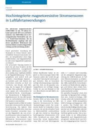
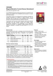
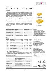
<strong>CMS2005</strong><strong>MagnetoResistive</strong> <strong>Current</strong> <strong>Sensor</strong> (I PN = 5 A)Data sheetThe CMS2000 current sensor family is designed for highlydynamic electronic measurement of DC, AC, pulsed and mixedcurrents with integrated galvanic isolation. The <strong>MagnetoResistive</strong>technology enables an excellent dynamic response without thehysteresis that is present in iron core based designs.The CMS2000 product family offers PCB-mountable THTcurrent sensors from 5 A up to 50 A nominal current for industrialapplications.<strong>CMS2005</strong>Product overviewQuick reference guide1)2)3)Product description Package Delivery Type<strong>CMS2005</strong>-SP3 THT Tray<strong>CMS2005</strong>-SP10 THT TraySymbol Parameter Min. Typ. Max. UnitV CC Positive supply voltage +11.4 +15.0 +15.7 VV EE Negative supply voltage -11.4 -15.0 -15.7 VI PN Primary nominal current (RMS) - - 5 AI PR Primary measuring range 1) -15 - +15 Aε Σ,SP3 Overall accuracy for SP3 2) - - ±0.8 % of I PNε Σ,SP10 Overall accuracy for SP10 2) - - ±0.5 % of I PNf co Upper cut-off frequency (-3 dB) - 100 - kHzT amb Ambient temperature 3) -25 - +85 °CFor 3 s in a 60 s interval and V CC = ±15 V.ε Σ = ε G + ε lin with V CC = ±15 V, I P = I PN and T amb = 25 °C.Operating condition.Qualification overviewStandardCE-sign EN 61010RoHS-conform 2002/95/ECStatusCertifiedCertifiedFeatures•Based on the AnisotropicMagneto Resistive (AMR) effect•Measuring range up to 3 timesnominal current•Galvanic isolation betweenprimary and measurement circuit•Bipolar 15 V power supplyAdvantages•Excellent accuracy•Low temperature drift•Small and compact size•Highly dynamic response•Automatically mountable on PCB•Integrated burden resistor•Low primary inductance•Negligible hysteresisApplications•Solar power converters•AC variable speed drives•Converters for DC motor drives•Uninterruptible power supplies•Switched mode power supplies•Power supplies for weldingapplicationsUL Recognized Component E251279Certified<strong>CMS2005</strong>.DSE.01www.sensitec.com© Sensitec GmbHData sheetPage 1 of 7Subject to technical changesSeptember 3 rd 2012
<strong>CMS2005</strong><strong>MagnetoResistive</strong> <strong>Current</strong> <strong>Sensor</strong> (I PN = 5 A)Absolute maximum ratings ValuesIn accordance with the absolute maximum rating system (IEC60134).Symbol Parameter Min. Max. UnitV CC Positive supply voltage -0.3 +16 VV SS Negative supply voltage -16 +0.3 VI PM Maximum primary current 1) -50 +50 AT amb Ambient temperature -25 +85 °CT stg Storage temperature -25 +85 °C1)For 20 ms in a 20 s interval.Stresses beyond those listed under “Absolute Maximum Ratings” may cause permanent damage to the device.This is a stress rating only and functional operation of the device at these or any other conditions beyond thoseindicated in the operational sections of this specification is not implied. Exposure to absolute maximum ratingconditions for extended periods may affect device reliability.Electrical dataT amb = 25 °C; V CC = ±15 V; unless otherwise specified.Symbol Parameter Conditions Min. Typ. Max. UnitV CC Positive supply voltage +11.4 +15.0 +15.7 VV SS Negative supply voltage -11.4 -15.0 -15.7 VI PN Primary nominal current (RMS) - - 5 AI PR Measuring range 2) -15 - +15 AV outN Nominal output voltage (RMS) I P = I PN - 2.5 - VR M Internal burden resistor for output signal - - 150 ΩR P Resistance of primary conductor - - 12 mΩI C <strong>Current</strong> consumption I C = 22 + (I P /I PN ) · 23 22 - 91 mA2)For 3 s in a 60 s interval.Electrical dataT amb = 25 °C; V CC = ±12 V; unless otherwise specified.Symbol Parameter Conditions Min. Typ. Max. UnitV CC Positive supply voltage +11.4 +12.0 +12.6 VV SS Negative supply voltage -11.4 -12.0 -12.6 VI PN Primary nominal current (RMS) - - 5 AI PR Measuring range 3) -10 - +10 AV outN Nominal output voltage (RMS) I P = I PN - 2.5 - VR M Internal burden resistor for output signal - - 150 ΩR P Resistance of primary conductor - - 12 mΩI C <strong>Current</strong> consumption I C = 22 + (I P /I PN ) · 23 22 - 91 mA3)For 3 s in a 60 s interval.<strong>CMS2005</strong>.DSE.01www.sensitec.com© Sensitec GmbHData sheetPage 2 of 7Subject to technical changesSeptember 3 rd 2012
<strong>CMS2005</strong><strong>MagnetoResistive</strong> <strong>Current</strong> <strong>Sensor</strong> (I PN = 5 A)QualificationsSymbol Parameter Conditions Min. Typ. Max. UnitV I Isolation test voltage (RMS) 50/60 Hz, 60 s - 3.5 - kVV B Rated voltage (RMS) Pollution degree 2, Kat. II - 600 - VAccuracy of <strong>CMS2005</strong>-SP3T amb = 25 °C; V CC = ±15 V; unless otherwise specified.Symbol Parameter Conditions Min. Typ. Max. Unitε Σ Overall accuracy 1) I P = I PN - - ±0.8 % of I PNε off Offset error I P = 0 - - ±0.8 % of I PNε Lin Linearity error I P ≤ I PN - - ±0.1 % of I PNTε G Maximum temperature induced gain error T amb = (-25…+85)°C - - 150 ppm/K1)Tε off Maximum temperature induced offset error T amb = (-25…+85)°C - - ±1.0 % of I PNε Σ = ε G + ε Lin with ε G = gain error and ε Lin = linearity errorAccuracy of <strong>CMS2005</strong>-SP10T amb = 25 °C; V CC = ±15 V; unless otherwise specified.Symbol Parameter Conditions Min. Typ. Max. Unitε Σ Overall accuracy 2) I P = I PN - - ±0.5 % of I PNε off Offset error I P = 0 - - ±0.2 % of I PNε Lin Linearity error I P ≤ I PN - - ±0.1 % of I PNTε G Maximum temperature induced gain error T amb = (-25…+85)°C - - 150 ppm/K2)Tε off Maximum temperature induced offset error T amb = (-25…+85)°C - - ±1.0 % of I PNε Σ = ε G + ε Lin with ε G = gain error and ε Lin = linearity errorDynamic dataT amb = 25 °C; V CC = ±15 V; unless otherwise specified.Symbol Parameter Conditions Min. Typ. Max. Unitt ra Reaction time 10% I PN to 10% I out - - 0.15 µst ri Rise time 10% to 90% I out - - 1.7 µsf co Upper cut-off frequency -3 dB - 100 - kHzGeneral dataSymbol Parameter Conditions Min. Typ. Max. UnitT amb Ambient temperature -25 - +85 °CT stg Storage temperature -25 - +85 °CT Solder temperature For 7 seconds. - - 250 °Cm Mass - 4.0 - g<strong>CMS2005</strong>.DSE.01www.sensitec.com© Sensitec GmbHData sheetPage 3 of 7Subject to technical changesSeptember 3 rd 2012
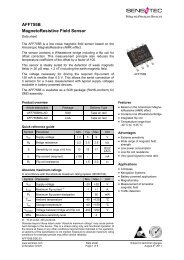
<strong>CMS2005</strong><strong>MagnetoResistive</strong> <strong>Current</strong> <strong>Sensor</strong> (I PN = 5 A)PinningPinSymbol Parameter1 V CC Positive supply voltage2 V EE Negative supply voltage3 GND Ground4 SGND Signal ground5 V out Signal output6 I in Primary current input7 I out Primary current outputFront ViewFig.1: Pinning of <strong>CMS2005</strong>.DimensionsDrilling templateAll dimensions in mmFig.2: Package outline with ± 0.2 mm and drilling plan with 0.05 mm tolerance.<strong>CMS2005</strong>.DSE.01www.sensitec.com© Sensitec GmbHData sheetPage 4 of 7Subject to technical changesSeptember 3 rd 2012
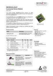
<strong>CMS2005</strong><strong>MagnetoResistive</strong> <strong>Current</strong> <strong>Sensor</strong> (I PN = 5 A)PCB Layout20 mmFig.3: Recommended clearance among each other.Fig.4: Recommended current path layout.The CMS2000 product familyThe <strong>CMS2005</strong> is a member of the CMS2000 product family offering PCB-mountable THT currentsensors from 5 A up to 50 A nominal current for various industrial applications.ProductI PN(A)I PR(A)ε Σ(% of I PN )ε off(% of I PN )Tε off(% of I PN )Package<strong>CMS2005</strong>-SP3 5 15 ±0.8 ±0.8 ±1.0<strong>CMS2005</strong>-SP10 5 15 ±0.5 ±0.2 ±1.0CMS2015-SP3 15 45 ±0.8 ±0.8 ±1.0CMS2015-SP10 15 45 ±0.5 ±0.2 ±1.0CMS2025-SP3 25 75 ±0.8 ±0.8 ±1.0CMS2025-SP10 25 75 ±0.5 ±0.2 ±1.0CMS2050-SP3 50 150 ±0.8 ±0.8 ±1.0CMS2050-SP7 50 220 ±0.8 ±1.6 ±0.9CMS2050-SP10 50 150 ±0.5 ±0.2 ±1.0I PN : Nominal primary current (RMS).I PR : Measurement range for 3 s in a 60 s interval (@SP7 only 20 ms in a 2 s interval).ε Σ : Overall accuracy ε Σ = ε G + ε lin with V CC = ±15 V, I P = I PN and T amb = 25 °C.ε off : Offset error with V CC = ±15 V, I P = 0 and T amb = 25 °C.Tε off : Maximum temperature induced offset error with T amb = (-25…+85) °C.<strong>CMS2005</strong>.DSE.01www.sensitec.com© Sensitec GmbHData sheetPage 5 of 7Subject to technical changesSeptember 3 rd 2012
<strong>CMS2005</strong><strong>MagnetoResistive</strong> <strong>Current</strong> <strong>Sensor</strong> (I PN = 5 A)Safety notesWarning!This sensor shall be used in electric and electronic devices according to applicable standardsand safety requirements. Sensitec’s datasheet and handling instructions must be complied with.Handling instructions for current sensors are available at www.sensitec.com.Caution! Risk of electric shock!When operating the sensor, certain parts, e. g. the primary busbar or the power supply, maycarry hazardous voltage. Ignoring this warning may lead to serious injuries!Conducting parts of the sensor shall not be accessible after installation.General informationProduct statusThe product is in series production. Note: The status of the product may have changed since this datasheet was published. The latest information is available on the internet at www.sensitec.com.DisclaimerSensitec GmbH reserves the right to make changes, without notice, in the products, includingsoftware, described or contained herein in order to improve design and/or performance. Information inthis document is believed to be accurate and reliable. However, Sensitec GmbH does not give anyrepresentations or warranties, expressed or implied, as to the accuracy or completeness of suchinformation and shall have no liability for the consequences of use of such information. SensitecGmbH takes no responsibility for the content in this document if provided by an information sourceoutside of Sensitec products.In no event shall Sensitec GmbH be liable for any indirect, incidental, punitive, special orconsequential damages (including but not limited to lost profits, lost savings, business interruption,costs related to the removal or replacement of any products or rework charges) irrespective thelegal base the claims are based on, including but not limited to tort (including negligence), warranty,breach of contract, equity or any other legal theory.Notwithstanding any damages that customer might incur for any reason whatsoever, Sensitec productaggregate and cumulative liability towards customer for the products described herein shall be limitedin accordance with the General Terms and Conditions of Sale of Sensitec GmbH.Nothing in this document may be interpreted or construed as an offer to sell products that is openfor acceptance or the grant, conveyance or implication of any license under any copyrights, patentsor other industrial or intellectual property rights.Unless otherwise agreed upon in an individual agreement Sensitec products sold are subject to theGeneral Terms and Conditions of Sales as published at www.sensitec.com.<strong>CMS2005</strong>.DSE.01www.sensitec.com© Sensitec GmbHData sheetPage 6 of 7Subject to technical changesSeptember 3 rd 2012
<strong>CMS2005</strong><strong>MagnetoResistive</strong> <strong>Current</strong> <strong>Sensor</strong> (I PN = 5 A)Application informationApplications that are described herein for any of these products are for illustrative purposes only.Sensitec GmbH makes no representation or warranty – whether expressed or implied – that suchapplications will be suitable for the specified use without further testing or modification.Customers are responsible for the design and operation of their applications and products usingSensitec products, and Sensitec GmbH accepts no liability for any assistance with applications orcustomer product design. It is customer’s sole responsibility to determine whether the Sensitecproduct is suitable and fit for the customer’s applications and products planned, as well as for theplanned application and use of customer’s third party customer(s). Customers should provideappropriate design and operating safeguards to minimize the risks associated with their applicationsand products.Sensitec GmbH does not accept any liability related to any default, damage, costs or problem whichis based on any weakness or default in the customer’s applications or products, or the application oruse by customer’s third party customer(s). Customer is responsible for doing all necessary testing forthe customer’s applications and products using Sensitec products in order to avoid a default of theapplications and the products or of the application or use by customer’s third party customer(s).Sensitec does not accept any liability in this respect.Life critical applicationsThese products are not qualified for use in life support appliances, aeronautical applications ordevices or systems where malfunction of these products can reasonably be expected to result inpersonal injury.Sensitec GmbHGeorg-Ohm-Straße 1135633 LahnauGermanyFon +49 (0) 6441 9788-0Fax +49 (0) 6441 9788-17E-Mail info@sensitec.comwww.sensitec.comSolutions for measuring:•Position•Angle•Magnetic field•<strong>Current</strong>Copyright © 2012 by Sensitec GmbH, GermanyAll rights reserved. No part of this document may be copied or reproduced in any form or by any means withoutthe prior written agreement of the copyright owner. The information in this document is subject to change withoutnotice. Sensitec GmbH does not assume any liability for any consequence of its use.www.sensitec.com© Sensitec GmbHData sheetPage 7 of 7Subject to technical changesSeptember 3 rd 2012