Control and Automation
Control and Automation - Vynco
Control and Automation - Vynco
- No tags were found...

Create successful ePaper yourself
Turn your PDF publications into a flip-book with our unique Google optimized e-Paper software.
GE Consumer & IndustrialPower Protection<strong>Control</strong> <strong>and</strong> <strong>Automation</strong>For industrial applications ED.03Everything is under controlGE imagination at work
<strong>Control</strong> <strong>and</strong> <strong>Automation</strong>Plug-in relays <strong>and</strong> Auxiliary contactorsMotor protection devicesContactors <strong>and</strong> Thermal overload relaysMotorstarters<strong>Control</strong> <strong>and</strong> signalling unitsElectronic relaysLimit switchesSpeed drive unitsMain switchesNumerical indexABCDEFGHIX
<strong>Control</strong> <strong>and</strong> <strong>Automation</strong>ACDPlug-in relays <strong>and</strong>Auxiliary contactorsContactors <strong>and</strong>Thermal overload relaysMotorstartersSeries PRC - Plug-in relaysMiniature plug-in relaysSt<strong>and</strong>ard 8-11 pin plug-inrelaysInterface relay! A.2Series M - Minicontactors3 <strong>and</strong> 4P (4NO, 2NO+2NC,4NC) 6,9 <strong>and</strong> 12A (AC-3)20A (AC-1)<strong>Control</strong> circuit AC <strong>and</strong> DC! C.2CoordinationLink modules for mechanical<strong>and</strong> electrical connection ofthe manual motor starter<strong>and</strong> the M/CL contactorranges! D.2Extended indexSeries M - Auxiliary minicontactorslth = 16A! A.16Series RL - Auxiliary contactorslth = 20A! A.22BMotor protection devicesSeries SFK -Motor protection circuit breakerThermal <strong>and</strong> magnetic protectionof AC <strong>and</strong> DC motorsSetting ranges from 0.1to 25A! B.2Surion - Manual motor starterThermal <strong>and</strong> magnetic protection- Magnetic protectionSetting ranges from 0.1to 63A! B.8Series CL - Contactors3 <strong>and</strong> 4P (4NO, 2NO+2NC)9 to 105A (AC-3) 25 to 140A(AC-1) AC, DC <strong>and</strong> withelectronic module! C.10Series CK - Contactors3 <strong>and</strong> 4P (4NO) 150 to 825A(AC-3) 200 to 1250A (AC-1)AC, DC <strong>and</strong> with electronicmodule! C.18Series MTO - Thermal overload relaysFor minicontactors series Mfrom 0.11 to 14A! C.60Series RT - Thermal overload relaysFor contactors series CL <strong>and</strong>CK from 0.16 to 850AClass 10A, 10, 20, 30! C.62Series RE - Electronic overload relaysFor contactors series CLfrom 0.1 to 150A! C.66Series CSCN -Contactors for capacitors switchingDirect-on-line startersSeries M: 6 to 12A (AC-3)Series CL: 9 to 105A (AC-3)Series CK: 150 to 825A (AC-3)! D.18Reversing startersSeries M: 6 to 12A (AC-3)Series CL: 9 to 105A (AC-3)Series CK: 150 to 825A (AC-3)! D.20Star-delta startersSeries CLSeries CK! D.22ASTAT S - Soft starterSmall soft starter withintegral by-pass! D.66ASTAT XT - Digital Soft StarterDigital Soft Starter for3 phase st<strong>and</strong>ardinduction motors! D.71! C.78Series 390.R - Clapper contactors! C.862
<strong>Control</strong> <strong>and</strong> <strong>Automation</strong>EF<strong>Control</strong> <strong>and</strong> signalling unitsElectronic relaysSeries P9 - Panel mounting -Units Ø 22 mmSeries IP - Foot switchesSeries NMV - Multivoltage relays22.5mm moduleDirect supply voltage (24-240V AC/DC)With transformer! E.8! E.66! F.3Series P9 - Base mounting! E.23Series P9 - Push-button stations! E.24Safety foot switches! E.68Series 105 - Signalling devices! E.69Series D - Single voltage electronic timers45mm moduleDirect supply voltage! F.4Liquid level detectors45 mm moduleDIN mounting! F.4Extended indexSeries P9 - Equipped boxesEarth leakage relays45 mm moduleDirect supply voltageWith transformer! E.27! F.4Series P9 - Common accessoriesProtection relays45 mm moduleDirect supply voltageWith transformer! E.30! F.5Series 077 - Units Ø 30 mmDetection relaysDirect supply voltageWith transformer! E.42! F.6Series NLT - Light towers<strong>Control</strong> <strong>and</strong> protection relays! E.60! F.63
<strong>Control</strong> <strong>and</strong> <strong>Automation</strong>GLimit switchesHSpeed drive unitsIMain switchesExtended indexSeries IS <strong>and</strong> IMMetal <strong>and</strong> ThermoplasticEN 50041Positive openingSeries IUGSeries IZSeries 114FCT! G.2Thermoplastic EN 50047Positive opening! G.4Thermoplastic miniaturedesign! G.6Three pole limit switchesThermoplasticPositive openingVAT20VAT200VAT300Single-phase or three-phasedigital inverters for controllingthe speed of threephaseinduction AC motorsfrom 0.2 to 2.2 kWIP20 or IP65! H.2From 0.4 to 2.2kW at 200V,single phase power supplyFrom 0.4 to 7.5kW at 200V,three phase power supplyFrom 0.75 to 11kW at 400V,three phase power supply! H.8Three phase drives forAC motors 220-240V or380-480V. Covering powerratings from 0.75kW up to475kW in normal duty, or upto 400kW in heavy duty! H.18Series ML - st<strong>and</strong>ard programmeMain switches <strong>and</strong> Emergency-stopswitches formachinery! I.4Series ML - enclosed switches! I.7! G.8Series 115 - Pressure switchesBellows typePiston type! G.164
<strong>Control</strong> <strong>and</strong> <strong>Automation</strong>• Go to www.ge.com/eu/powerprotection <strong>and</strong>click on e-Catalogue• Use the Quick search to directly searchon product number or keyword• Another way to find a product easily is byusing “parametric search”, entering thetechnical characteristics of the productyou are looking fore-catalogue• Compare many products next to eachother, looking at common <strong>and</strong>comparable features• Every product page contains all availabledata: technical specifications, mountinginstructions, dimensional drawings,texts for tenders...All product info in one centralisedplace on our siteAll product info is downloadable,printable <strong>and</strong> emailable !Always the latest up-to-date info ath<strong>and</strong> !5
Everything is
Plug-in relays & Auxiliary contactorsSeries PRC - Plug-in relaysA.3A.7A.14Order codesTechnical dataDimensionsSeries M - Auxiliary minicontactorsA.17Order codesA.26Technical dataA.31Terminal numberingA.40DimensionsPlug-in relays <strong>and</strong> Auxiliary contactorsAA.23Series RL - Auxiliary contactorsOrder codesMotor protection devicesBA.34A.36Technical dataTerminal numberingContactors <strong>and</strong> Thermal overload relaysCA.42DimensionsMotorstartersD<strong>Control</strong> <strong>and</strong> signalling unitsEElectronic relaysFLimit switchesGSpeed drive unitsHMain switchesIunder controlNumerical index XA.1
Series PRCPlug-in auxiliary relays• AC or DC coils• Lockable test button with mechanical flag indicator.• Sockets with rear 35 mm rail (EN 50022) mounting.• With LED indicator incorporated.Miniature relaysTypes Poles AC ratingsPRC4M2...2 CO12A/250VSocketsTypesPRCG-ES15/2NPRC4M3...3 CO10A/250VPRCG-ES15/3NPlug-in relaysABCApprovalsAccording to types:Plug-in relaysCECSAcULVDESocketsCECSAcULPRC4M4...4 CO6A/250VSt<strong>and</strong>ard 8-11 pin relaysTypes Poles AC ratingsPRC2P2...2 CO10A/250VPRC3P3...3 CO10A/250VInterface relay moduleTypes Poles AC ratingsPRC1S1...1 CO6A/250VFor use with PLC systemsPRC1T1...PRC1T2...1 CO2 CO16A/250V8A/250VPRCG-ES15/4NSocketsTypesPRZ8PRZ11SocketsTypes-PRCGZT80PRCGZT80DEFCatalogue number structureSeriesSt<strong>and</strong>ard 8 pin = 2St<strong>and</strong>ard 11 pin = 3Square base miniature = 4Input/output interface relay = 11234No. of contactsSpecial executionsD = Free wheeling diode (DC only)GPlug-in relaysP R CLLEDHIXTypeSt<strong>and</strong>ard Pin = PMiniature = MInterface = S - TContact materialsSt<strong>and</strong>ard AgNi = 0Gold plated cont. 5µ Au = 2St<strong>and</strong>ard AgSnO2 for Interface relays = 3Coil voltageA = 6VB = 12VD = 24VG = 48VJ = 110V (DC)J = 120V (AC)N = 230V (AC)VoltageA = ACC = DCB = AC/DCOrder codesModules for socketsTechnical characteristicsDimensions!!!!pg. A.3pg. A.6pg. A.7pg. A.14A.2
Series PRC2 changeovercontactsMiniature plug-in relaysRatingsAC12A/250VContactsVoltageWith LEDSt<strong>and</strong>ard material Cat. no. Ref. no. Pack0AgNiAC50/60 HzDCDCDiode12V24V48V120V230V12V24V48V110V12V24V48V110VPRC4M20ABLPRC4M20ADLPRC4M20AGLPRC4M20AJLPRC4M20ANLPRC4M20CBLPRC4M20CDLPRC4M20CGLPRC4M20CJLPRC4M20DCBLPRC4M20DCDLPRC4M20DCGLPRC4M20DCJL220710220711220712220715220717220713220714220716220718220754220755220756220757101010101010101010101010103 changeovercontacts10A/250V0AgNiAC50/60 HzDCDCDiode12V24V48V120V230V12V24V48V110V12V24V48V110VPRC4M30ABLPRC4M30ADLPRC4M30AGLPRC4M30AJLPRC4M30ANLPRC4M30CBLPRC4M30CDLPRC4M30CGLPRC4M30CJLPRC4M30DCBLPRC4M30DCDLPRC4M30DCGLPRC4M30DCJL22105122105222105322105622105822105422105522105722105922107422107522107622107710101010101010101010101010Order codesA4 changeovercontacts6A/250V0AgNiAC50/60 HzDCDCDiode12V24V48V120V230V12V24V48V110V12V24V48V110VPRC4M40ABLPRC4M40ADLPRC4M40AGLPRC4M40AJLPRC4M40ANLPRC4M40CBLPRC4M40CDLPRC4M40CGLPRC4M40CJLPRC4M40DCBLPRC4M40DCDLPRC4M40DCGLPRC4M40DCJL22180922181022181122181422181622181222181322181522181722185122185222185322185410101010101010101010101010BCDESocketsCat. no. Ref. no. PackFFor PRC4M2...2 changeovercontactsScrew terminalsTwo levelsSocketFixing clipRetainer/ExtractorIdentification plateMetalWhite plasticPRCG-ES15/2NPRCG1052PRCMS35PRCTR122091222091422091522091610101010GHFor PRC4M3...3 changeovercontactsScrew terminalsTwo levelsSocketFixing clipRetainer/ExtractorIdentification plateMetalWhite plasticPRCG-ES15/3NPRCG1052PRCMS35PRCTR122144222091422091522091610101010IXFor PRC4M4...4 changeovercontactsScrew terminalsTwo levelsSocketFixing clipRetainer/ExtractorIdentification plateMetalWhite plasticPRCG-ES15/4NPRCG1052PRCMS35PRCTR122193422091422091522091610101010A.3
Series PRCMiniature plug-in relaysPlug-in relaysABCDEFGHContactsNumber of contactsSt<strong>and</strong>ard materialOptional materialVoltageMax. switching AC/DC (poll. 3)voltage AC (poll. 2)Min. switching voltage AC/DCCurrentRated load AC1 (A)AC15(A)DC1(A)Min. switching current (mA)Max. inrush current(A)Rated current(A)Max. breaking capacity (VA)Resistance(mΩ)Max. operating frequencyAt rated load cycles/hourNo loadcycles/hourCoilRated voltage AC 50/60Hz (V)DC(V)Must release ACtime voltage DCOperating range of supply voltageRated power AC 50Hz (VA)consumption 60Hz (VA)DC(W)AC/DC(W)InsulationInsulation categoryInsulation rated voltage (VAC)Dielectric Coil-Contact (VAC)strength Contact-Contact (VAC)Pole-Pole (VAC)Contact coil Clearance mmdistance Creepage mmGeneral dataOperating time AC(ms)(typical value) DC(ms)Release time AC (ms)(typical value) DC(ms)Electrical life ResistiveCos ϕ ϕMechanical life (cycles)Ambient Storage (ºC)temperature Operating AC (ºC)DC (ºC)Cover protection categoryShock resistance(G)Vibration resistance(G)PRC4M20...2 pole2 changeoverAgNiAgNi/Au 5µ250V400V5V12 (250V AC)4 (250V AC)12 (24V DC)524123000H100(100mA, 24V)1200180006 ... 2405 ... 220G0.2 UnG0.1 UnTable 1, 21.51.30.9-C250250250015002500G 2.5G 4101383G 10 5(12A, 250V AC)See curvesG 10 7-40 ... +85-40 ... +55-40 ... +70IP40105(for 10..150Hz)PRC4M30...3 pole3 changeoverAgNiAgNi/Au 5µ250V400V5V10 (250V AC)4 (250V AC)10 (24V DC)520102500H100(100mA, 24V)1200180006 ... 2405 ... 220G0.2 UnG0.1 UnTable 1, 21.61.30.9-C250250250015002500G 2.5G 4101383G 10 5(10A, 250V AC)See curvesG 10 7-40 ... +85-40 ... +55-40 ... +70IP40105(for 10..150Hz)PRC4M40...4 pole4 changeoverAgNiAgNi/Au 5µ250V400V5V6 (250V AC)2,5 (250V AC)6 (24V DC)51261500≤100(100mA, 24V)1200180006 ... 2405 ... 220G0.2 UnG0.1 UnTable 1, 21.61.30.9-B250250250015002000G 1.6G 3.2101383G 10 5(6A, 250V AC)See curvesG x10 7-40 ... +85-40 ... +55-40 ... +70IP40105(for 10..150Hz)Table 1. Coil data DC versionRated Coil Coil operating range V DCvoltage resistance Min. Max.V DC Ω (at 20ºC) (at 55ºC)12 160 9.6 13.224 640 19.2 26.448 2600 38.4 52.8110 13600 88 121220 54000 176 242Table 2. Coil data AC 50/60Hz versionRated Coil Coil operating range V ACvoltage resistance Min. Max.V AC Ω (at 20ºC) (at 55ºC)12 39 9.6 13.224 158 19.2 26.448 640 38.4 52.8120 3770 88 121230 16100 184 253IXA.8
Series PRCMiniature 2 pole plug-in relaysElectrical life at AC resistive loadElectrical life reduction factor at ACinductive loadMax. DC resistive load breakingcapacityNumber of cycles (N)Miniature 3 pole plug-in relaysElectrical life at AC resistive loadNumber of cycles (N)Breaking capacity (kVA). . . . . .Breaking capacity (kVA)Electrical life reduction factor at ACinductive loadReduction factor (F)Miniature 4 pole plug-in relaysElectrical life at AC resistive loadReduction factor (F)......cosϕ. . . .Power factorN cosϕ = N x F. . .cosϕ.Power factorN cosϕ = N x FElectrical life reduction factor at ACinductive loadCurrent (A)Max. DC load breaking capacityCurrent (A)......Voltage (V)resistive load T = 0msinductive load T = 40msVoltage (V)Max. DC resistive load breakingcapacityTechnical dataABCDEFNumber of cycles (N). .Breaking capacity (kVA)Reduction factor (F).... . . .cosϕPower factorN cosϕ = N x FCurrent (A)....Voltage (V)GHIXA.9
Series PRCSt<strong>and</strong>ard 8-11 pin plug-in relaysPlug-in relaysABCDEFGHContactsNumber of contactsSt<strong>and</strong>ard materialOptional materialVoltageMax switching AC/DC (poll. 3)voltage AC (poll. 2)Min switching voltage AC/DCCurrentRated load AC1 (A)AC15(A)DC1(A)Min. switching current(mA)Max. inrush current(A)Rated current(A)Max. breaking capacity(VA)Resistance(mΩ)Max. operating frequencyAt rated loadcycles/hourNo loadcycles/hourCoilRated voltage AC 50/60Hz (V)DC(V)Must release time ACvoltageDCOperating range of supply voltageRated power AC 50Hz (VA)consumption 60Hz (VA)DC(W)AC/DC(W)InsulationInsulation categoryInsulation rated voltage(VAC)Dielectric strength Coil-Contact (VAC)Contact-Contact (VAC)Pole-Pole (VAC)Distance Clearance mmcontact coil Creepage mmGeneralOperating time AC (ms)(typical value) DC (ms)Release time AC (ms)(typical value) DC (ms)Electrical lifeResistiveCos ϕMechanical life (cycles)Ambient Storage (ºC)temperature Operating AC (ºC)Cover protection categoryShock resistanceVibration resistanceDC(ºC)(G)(G)Electrical life at AC resistive loadPRC2P20...St<strong>and</strong>ard 8-pin2 changeoverAgNiAgNi/Au 5µ250V400V10V (AgNi)5V (AgNi/Au 5µ)10 (250V AC)4 (250V AC)10 (24V DC)530102500H100 (100mA, 24V)1200120006 ... 2406 ... 220G0.15 UnG0.1 UnTable 1, 22,72,51,5-C250250250015002000G 3G 4.21212107G 2x10 5 (10A, 250V AC)See curvesG 2x10 7-40 ... +85-40 ... +55-40 ... +70IP40105PRC3P30...St<strong>and</strong>ard 11-pin3 changeoverAgNiAgNi/Au 5µ250V400V10V (AgNi)5V (AgNi/Au 5µ)10 (250V AC)4 (250V AC)10 (24V DC)530102500H100 (100mA, 24V)1200120006 ... 2406 ... 220G0.15 UnG0.1 UnTable 1, 22,72,51,5-C250250250015002000G 3G 4.21212107G 2x10 5 (10A, 250V AC)See curvesG 2x10 7-40 ... +85-40 ... +55-40 ... +70IP40105Electrical life reduction factor at ACinductive loadTable 1. Coil data DC versionRated Coil Coil operating range V DCvoltage resistance Min. Max.V DC Ω (at 20ºC) (at 55ºC)12 110 9.6 13.224 430 19.2 26.448 1750 38.4 52.8110 9200 88 121220 37000 176 242Table 2. Coil data AC 50/60Hz versionRated Coil Coil operating range V ACvoltage resistance Min. Max.V AC Ω (at 20ºC) (at 55ºC)12 18.5 9.6 13.224 75 19.2 26.448 305 38.4 52.8120 1910 96 132230 7080 184 253Max. DC load breaking capacityIXNumber of cycles (N). . . . . .Breaking capacity (kVA)N cosϕ = N x FReduction factor......... . . . . . . . .Power factorN cosϕ = N x FCurrent (A)....resistive load T = 0msinductive load T = 40msVoltage (V)A.10
Series PRCInterface plug-in relaysPRC1S13...ContactsNumber of contactsSt<strong>and</strong>ard materialOptional materialVoltageMax switching AC/DC (poll. 3)voltage AC (poll. 2)Min switching voltage AC/DCCurrentRated load AC1 (A) 6 (250V AC)AC15(A)DC1(A)Min. switching current(mA)Max. inrush current (A)Rated current(A)Max. breaking capacity(VA)Resistance(mΩ)Max. operating frequencyAt rated loadNo loadCoilRated voltage AC/DC (V)AC 50/60Hz(V)DC(V)Must release time ACvoltageDCOperating range of supply voltageRated power AC 50Hz (VA)consumption 60Hz (VA)DCAC/DC(W)(W)InsulationInsulation categoryInsulation rated voltage(VAC)Dielectric strength Coil-Contact (VAC)Contact-Contact (VAC)Pole-Pole(VAC)Distance Clearance mmcontact coil Creepage mmGeneralOperating time AC (ms)(typical value) DC (ms)Release time AC (ms)(typical value) DC (ms)Electrical lifeResistiveCos ϕMechanical life (cycles)Ambient Storage (ºC)temperature Operating AC (ºC)Cover protection categoryShock resistanceVibration resistanceDC(ºC)(G)(G)1 changeoverAgSnO2AC 250V / DC 150VAC 400V / DC 300V12V6 (24V DC)101561500VH100(100mA, 24V)360 cycles/hour72000 cycles/hour24, 23023012, 24G0,2 UnG0,1 UnSee Table 10.6...1.9-0.330.48 (at 24V), 1.8 (at 230V)C25040040001000-G 8G 88615820x10 6-40 ... +70-20 ... +55-20 ... +55IP20100.062’’ DA(10 ... 55Hz)Table 1. Interface relayRatedCoil operating range V DCvoltage Min. Max.V12 DC 9 1724 DC 17 3024 AC/DC 18 30230 AC 80 250230 AC/DC 185 250Technical dataABCDEFGHIXA.11
Series PRCInterface relay for PLC systemsPRC1T10...Plug-in relaysABCDEFGContactsNumber of contactsSt<strong>and</strong>ard materialOptional materialVoltageMax. switching voltageAC/DCMin. switching voltageAC/DCCurrentRated load AC1 (A)DC1(A)Min. switching current(mA)Max. inrush current(A)Rated current(A)Max. breaking capacity(VA)Min. breaking capacity(W)Resistance(mΩ)Max. operating frequencyAt rated loadNo loadCoilRated voltage AC 50/60Hz (V)DC(V)Must release time ACvoltageDCOperating range of supply voltageRated power AC (VA)consumption DC (W)InsulationInsulation categoryInsulation rated voltage(VAC)Dielectric strength Coil-Contact (VAC)Contact-Contact (VAC)Pole-Pole(VAC)Distance Clearance mmcontact coil Creepage mmGeneralOperating time AC (ms)(typical value) DC (ms)Release time AC (ms)(typical value) DC (ms)Electrical life Resistive (s)Cos ϕL/R = 40msMechanical life (cycles)Ambient Storage (ºC)temperature Operating (ºC)Cover protection categoryShock resistanceVibration resistance(G)(G)1 changeoverAgNiAC 400V / DC 300V5V16 (250V AC)16 (24V DC)5301640000,3H100 (at 1A, 24V)600 cycles/hour72000 cycles/hour24,120, 23012, 24, 110G0.15 UnG0.1 UnSee Table 1, 20.750.4C25040050001000-G 10G 107753G 0.7 x 10 5 (at 16A, 250VAC)See curvesG 10 5 (at 0.12A, 220VDC)3x10 7-40 ... +70-40 ... +70IP403010 (for 10 ... 150Hz)Table 1. Coil data DC versionRated Coil resistance Coil operating range V DCvoltage (±10%) at20ºC U Min. U Max.V DC Ω12 360 8.4 30.624 1440 16.8 61.2110 25200 77 280Table 2. Coil data AC 50/60Hz versionRatedCoil resistance Coil operating range V ACvoltage (±10%) at20ºC U Min. U Max.V AC Ω24 400 19.2 28.8120 10200 96 144230 38500 184 276HElectrical life at AC resistive loadElectrical life reduction factor at ACinductive loadMax. DC load breaking capacityIXNumber of cycles (N)Reduction factor...Current (A).. . . . .Breaking capacity (kVA). . .N cosϕ = N x FPower factor.Voltage (V)A.12
Series PRCInterface relay for PLC systemsPRC1T20...ContactsNumber of contactsSt<strong>and</strong>ard materialOptional materialVoltageMax. switching voltageAC/DCMin. switching voltageAC/DCCurrentRated load AC1 (A)DC1(A)Min. switching current(mA)Max. inrush current(A)Rated current(A)Max. breaking capacity(VA)Min. breaking capacity(W)Resistance(mΩ)Max. operating frequencyAt rated loadNo loadCoilRated voltage AC 50/60Hz (V)DC(V)Must release time ACvoltageDCOperating range of supply voltageRated power AC (VA)consumption DC (W)InsulationInsulation categoryInsulation rated voltage(VAC)Dielectric strength Coil-Contact (VAC)Contact-Contact (VAC)Pole-Pole(VAC)Distance Clearance mmcontact coil Creepage mmGeneralOperating time AC (ms)(typical value) DC (ms)Release time AC (ms)(typical value) DC (ms)Electrical life Resistive (s)Cos ϕL/R = 40msMechanical life (cycles)Ambient Storage (ºC)temperature Operating (ºC)Cover protection categoryShock resistanceVibration resistance(G)(G)2 changeoverAgNiAC 400V / DC 300V5V8 (250V AC)8 (24V DC)515820000,3H100 (at 1A, 24V)600 cycles/hour72000 cycles/hour24, 23012, 24G0.15 UnG0.1 UnSee Table 1, 20.750.4C25040050001000-G 10G 107753G 0.7 x 10 5 (at 8A, 250VAC)See curvesG 10 5 (at 0,12A, 220VDC)3x10 7-40 ... +70-40 ... +70IP402010 (for 10 ... 150Hz)Table 1. Coil data DC versionRated Coil resistance Coil operating range V DCvoltage (±10%) at 20ºC U Min. U Max.V DC Ω12 360 8.4 30.624 1440 16.8 61.2110 25200 77 280Table 2. Coil data AC 50/60 Hz versionRated Coil resistance Coil operating range V ACvoltage (±10%) at 20ºC U Min. U Max.V AC Ω24 400 19.2 28.8120 10200 96 144230 38500 184 276Technical dataABCDEFGElectrical life at AC resistive loadElectrical life reduction factor at ACinductive loadMax. DC load breaking capacityHNumber of cycles (N)Reduction factor...Current (A)IX.. . . .Breaking capacity (kVA). . .Power factorN cosϕ = N x F.Voltage (V)A.13
Series PRCDimensional drawings2 polesPlug-in relays..MiniatureSt<strong>and</strong>ard 8-11 pin. ..........A3 poles... .......Socket. Screw terminals. One level..B.4 polesCD...E..Socket. Solder terminalsFGSocket. Screw terminals. Two levels.H.I..XA.14
Series PRCInterface relaySocket for miniature P.C.B. relays. ...DimensionsABCDEFGHIXA.15
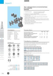
Series MAuxiliary minicontactorsABCDEFGHIXA.16St<strong>and</strong>ardsIEC/EN 60947-5-1IEC/EN 60947-1EN 50002EN 50005EN 50011UL 508ApprovalscULusSEMKOLloyd’sRegisterDEMKOSETIBureauVeritasOrder codesAuxiliary contacts blocksAccessoriesTechnical dataCombinations of contactsDimensionsBS 4794CENELEC HD 420NFC 63-110NFC 63-140CSA C22.2/14VDE 0660!!!!!!NEMKOCERINApg. A.17pg. A.18pg. A.20pg. A.26pg. A.32pg. A.40Auxiliary minicontactorsIth = 16A• <strong>Control</strong> circuit: Alternating current up to 600VDirect current up to 250V• Terminal numbering in accordance with EN 50011• Fixing system for rapid <strong>and</strong> simple mounting by clamping onto st<strong>and</strong>ard35 mm DIN rail (EN 50022).• Screw <strong>and</strong> push-on terminals protected against accidental contacts inaccordance with VDE 0106 T.100 <strong>and</strong> VBG4.• Printed circuit version.• Ring terminal version.• Facility to mount instant or timed auxiliary contact blocks <strong>and</strong> voltagesupressor blocks.• Maximum number of auxiliary contacts to add: 6• Degree of protection IP20 (EN 60529).• According to IEC/EN 60947-1.General dataMaximum number of contacts (MCR...) 4Rated thermal current (Ith) θ H 60º (A) 16Rated operational voltage (Ue) acc. IEC 60947-1 (V) 690Insulation voltage (Ui) acc. IEC 60947-1 (V) 750Utilisation category:AC-15 V 110 220/240 380/400 415 440 500 660/690A 6 6 4 4 3 2.5 1.5DC-13V 24 48 110 220A 5 3.5 1.2 0.6St<strong>and</strong>ard voltagesTo complete the catalogue number, replace the symbol © by the codecorresponding to the voltage <strong>and</strong> frequency of the control circuit.Alternating current (V). Bifrequency coil© 10 1 2 9 3 4 5 6 7 8 12 13AC 12 24 42 48 110 120 220 230 240 440 380 40050/60Hz 115Voltage operating limits of dual-frequency coil:at 60Hz = 0.85 a 1.1 x Usat 50Hz = 0.8 a 1.1 x Us for uninterrupted duty (ED=100%), temperature = 40ºCAlternating current (V)© A E G K M N S U W YAC 48 115 220 260 380 415 50050Hz 127 240 400 440AC 6 32 60 208 240 440 480 60060Hz 220 277Direct current (V)© A B C D E F G H I J K L N 17 R S 16DC 6 12 32 24 36 42 48 60 72 110 120 125 220 230 240 250 440Direct current (V) - Wide voltage range© WD WE WG WI WJ WNDC 24 33 48 72 110 220
Series MAuxiliary minicontactorsContacts acc.EN 50011•3 •3•4 •4•1 •1•2 •2<strong>Control</strong> circuit: alternating currentCat. no. (1)Ref. no. seebottomScrew terminal40E 4 0 MCRA040AT © 5 MCRC040AT © 1031E 3 1 MCRA031AT © 5 MCRC031AT © 1022E 2 2 MCRA022AT © 5 MCRC022AT © 1013E 1 3 MCRA013AT © 504E 0 4 MCRA004AT © 5Pack<strong>Control</strong> circuit: direct currentCat. no. (1)Ref. no.see bottomPackRing terminal40E 4 0 MCRA040AR © 5 MCRC040AR © 1031E 3 1 MCRA031AR © 5 MCRC031AR © 1022E 2 2 MCRA022AR © 5 MCRC022AR © 1013E 1 3 MCRA013AR © 504E 0 4 MCRA004AR © 5Terminal: faston 2x2,8 insulated (2)40E 4 0 MCRA040AF © 5 MCRC040AF © 1031E 3 1 MCRA031AF © 5 MCRC031AF © 1022E 2 2 MCRA022AF © 5 MCRC022AF © 1013E 1 3 MCRA013AF © 504E 0 4 MCRA004AF © 5Terminal: printed circuit40E 4 0 MCRA040AI © 5 MCRC040AI © 1031E 3 1 MCRA031AI © 5 MCRC031AI © 1022E 2 2 MCRA022AI © 5 MCRC022AI © 1013E 1 3 MCRA013AI © 504E 0 4 MCRA004AI © 5Order codesABCSpare coilMB0A © 10 MB0C © 10DScrewterminalSpare coil(1) To complete the catalogue number, replace the symbol © by the code corresponding to the voltage <strong>and</strong> frequencyof the control circuit. (see pg.A.16).(2) Terminal: - with wire 1.5 mm 2 : Ie = 16A - with wire 1 mm 2 : Ie = 10AInsulated terminal type B2.8x0.8 with wire 1 mm 2 : Ie = 8A to DIN 46247Faston terminal 1 x 6.3 on request, replace the letter F by H in the catalogue numberAuxiliary minicontactors interfaceContacts acc. toEN 50011•3 •3•4 •4•1 •1•2 •2<strong>Control</strong> circuit: direct current 24V / 1.2W (3) <strong>Control</strong> circuit: direct current 24V / 2W (4)Operating limitsfrom 19 to 30V (0.8-1.25xUs)Cat. no. Ref. no. PackOperating limitsfrom 17 to 30V (0.7-1.25xUs)Cat. no. Ref. no. Pack40E 4 0 MCRI040ATD 100530 10 MCRK040ATD 100533 1031E 3 1 MCRI031ATD 100531 10 MCRK031ATD 100534 1022E 2 2 MCRI022ATD 100532 10 MCRK022ATD 100535 10MB0ID 100470 10 MB0KD 100471 10EFGHIX(3) No possibility of adding instantaneous auxiliary blocks.(4) Facility to mount instantaneous auxiliary contact block of two contacts (MARN2...)or two instantaneous auxiliary contact blocks of one contact (MARL1...).For reference numbers,see chapter X, pg. X.2A.17
Series MInstantaneous auxiliary contacts blocksNumber of Combination withContacts acc. to EN 50005contacts MCRA040AT© (40E) Designationaccording to EN 50011 (block marking) •3 •3 •1 •1Cat. no. Ref. no. PackAuxiliary minicontactorsFront mounting•4 •4 •2 •2Screw terminal2 60E 20 2 0 MARN220AT 100994 102 51E 11 1 1 MARN211AT 100993 102 42E 02 0 2 MARN202AT 100992 10Ring terminal2 60E 20 2 0 MARN220AR 103349 102 51E 11 1 1 MARN211AR 103350 102 42E 02 0 2 MARN202AR 103351 10Screw terminal4 80E 40 4 0 MARN440AT 100991 104 71E 31 3 1 MARN431AT 100990 104 62E 22 2 2 MARN422AT 100989 104 53E 13 1 3 MARN413AT 100988 104 44E 04 0 4 MARN404AT 100987 10ABTerminal : Ring terminal4 80E 40 4 0 MARN440AR 103352 104 71E 31 3 1 MARN431AR 103353 104 62E 22 2 2 MARN422AR 103354 104 53E 13 1 3 MARN413AR 103355 104 44E 04 0 4 MARN404AR 103300 10CDEFGHIXA.18
Series MInstantaneous auxiliary contacts blocksContacts acc. to EN 50005Number of Combination withcontacts MCRA040AT© (40E) Designation •3 •3 •1 •1according to EN 50011 (Block marking)Cat. no. Ref. no. PackLateral mounting• One or two blocks to cover combinations of 5 or 6 contacts without increasing the height of the basic unit.Screw terminal1 50E 10 1 0 MARL110AT 100513 101 – 01 0 1 MARL101AT 100514 10•4 •4•2 •2Ring terminal1 50E 10 1 0 MARL110AR 103556 101 – 01 0 1 MARL101AR 103557 10Terminal : Faston 2x2,8 insulated (1)1 50E 10 1 0 MARL110AF 100515 101 – 01 0 1 MARL101AF 100516 10Order codesTerminal : Printed circuit1 50E 10 1 0 MARL110AI 100517 101 – 01 0 1 MARL101AI 100518 10• One or two additional blocks, when 9 or 10 contacts are required (combination possible with the front mounting block)• One or two additional blocks on both sides, to cover up to 8 contacts (combination only possible with lateral blocks)Screw terminal1 50E 10 1 0 MARL110ATS 100519 101 – 01 0 1 MARL101ATS 100520 10Ring terminal1 50E 10 1 0 MARL110ARS 103299 101 – 01 0 1 MARL101ARS 103298 10Terminal : Faston 2x2,8 insulated (1)1 50E 10 1 0 MARL110AFS 100521 101 – 01 0 1 MARL101AFS 100522 10Terminal : Printed circuit1 50E 10 1 0 MARL110AIS 100523 101 – 01 0 1 MARL101AIS 100524 10ABCDEFGH(1) Terminal with wire 1 mm 2 : Ie = 10AInsulated terminal type B2.8x0.8 with wire 1 mm 2 : Ie = 8AIXA.19
Series MAccessoriesFor use Time Function Uewith:Cat. no. Ref. no. PackElectronic timer blockLateral or front fixing on the contactorMCR..MC_ ... 0.5 - 60 sec. Delay ON 24 to 250V AC/DC MREBC10AC2 100541 10MCR..MC_ ... 0.2 - 24 sec. Delay ON 24 to 250V AC/DC MREBC20AC2 100542 10Auxiliary minicontactorsABCTimer fitmentVoltage suppresorblockMechanicalinterlockFor fixing onto 35mm DIN-rail (EN 5022)MREBC... MVB0R 100543 10For use Type <strong>Control</strong> Uewith:Connection <strong>and</strong> (plug-in) fixing onto front of the contactorMCRA,MC_ ... RC AC 12 to 60V 50/60Hz MP0AAE1 100544 10MCRA,MC_ ... RC AC 72 to 250V 50/60Hz MP0AAE2 100545 10MCRC,MC_ ... Diode DC 6 to 250V DC MP0CAE3 100546 10MCRC, MC_... Varistor AC/DC 24-48V MP0DAE4 100536 10For usewith:Kit comprising mechanical interlock <strong>and</strong> contactor jointing partsCat. no. Ref. no. PackCat. no. Ref. no. PackMCR, MC_ ... MMH0 100547 10DEFIdentificationFor usewith:Cat. no. Ref. no. PackMCR, MC_ ... Sheets of labels (10 sheets of 260 labels each) EAT 260 100548 1MCR, MC_ ... Labelling plate base. Plug-in labelling plate bases SPR 100549 1(50 pieces in one pack)GHIXA.20
Series MNotes. . . . . . . . . . . . . . . . . . . . . . . . . . . . . . . . . . . . . .. . . . . . . . . . . . . . . . . . . . . . . . . . . . . . . . . . . . . .. . . . . . . . . . . . . . . . . . . . . . . . . . . . . . . . . . . . . .. . . . . . . . . . . . . . . . . . . . . . . . . . . . . . . . . . . . . .. . . . . . . . . . . . . . . . . . . . . . . . . . . . . . . . . . . . . .. . . . . . . . . . . . . . . . . . . . . . . . . . . . . . . . . . . . . .. . . . . . . . . . . . . . . . . . . . . . . . . . . . . . . . . . . . . .. . . . . . . . . . . . . . . . . . . . . . . . . . . . . . . . . . . . . .. . . . . . . . . . . . . . . . . . . . . . . . . . . . . . . . . . . . . .. . . . . . . . . . . . . . . . . . . . . . . . . . . . . . . . . . . . . .. . . . . . . . . . . . . . . . . . . . . . . . . . . . . . . . . . . . . .. . . . . . . . . . . . . . . . . . . . . . . . . . . . . . . . . . . . . .. . . . . . . . . . . . . . . . . . . . . . . . . . . . . . . . . . . . . .. . . . . . . . . . . . . . . . . . . . . . . . . . . . . . . . . . . . . .. . . . . . . . . . . . . . . . . . . . . . . . . . . . . . . . . . . . . .. . . . . . . . . . . . . . . . . . . . . . . . . . . . . . . . . . . . . .. . . . . . . . . . . . . . . . . . . . . . . . . . . . . . . . . . . . . .. . . . . . . . . . . . . . . . . . . . . . . . . . . . . . . . . . . . . .. . . . . . . . . . . . . . . . . . . . . . . . . . . . . . . . . . . . . .. . . . . . . . . . . . . . . . . . . . . . . . . . . . . . . . . . . . . .. . . . . . . . . . . . . . . . . . . . . . . . . . . . . . . . . . . . . .. . . . . . . . . . . . . . . . . . . . . . . . . . . . . . . . . . . . . .. . . . . . . . . . . . . . . . . . . . . . . . . . . . . . . . . . . . . .. . . . . . . . . . . . . . . . . . . . . . . . . . . . . . . . . . . . . .. . . . . . . . . . . . . . . . . . . . . . . . . . . . . . . . . . . . . .. . . . . . . . . . . . . . . . . . . . . . . . . . . . . . . . . . . . . .. . . . . . . . . . . . . . . . . . . . . . . . . . . . . . . . . . . . . .. . . . . . . . . . . . . . . . . . . . . . . . . . . . . . . . . . . . . .. . . . . . . . . . . . . . . . . . . . . . . . . . . . . . . . . . . . . .. . . . . . . . . . . . . . . . . . . . . . . . . . . . . . . . . . . . . .. . . . . . . . . . . . . . . . . . . . . . . . . . . . . . . . . . . . . .. . . . . . . . . . . . . . . . . . . . . . . . . . . . . . . . . . . . . .. . . . . . . . . . . . . . . . . . . . . . . . . . . . . . . . . . . . . .. . . . . . . . . . . . . . . . . . . . . . . . . . . . . . . . . . . . . .. . . . . . . . . . . . . . . . . . . . . . . . . . . . . . . . . . . . . .. . . . . . . . . . . . . . . . . . . . . . . . . . . . . . . . . . . . . .. . . . . . . . . . . . . . . . . . . . . . . . . . . . . . . . . . . . . .. . . . . . . . . . . . . . . . . . . . . . . . . . . . . . . . . . . . . .. . . . . . . . . . . . . . . . . . . . . . . . . . . . . . . . . . . . . .. . . . . . . . . . . . . . . . . . . . . . . . . . . . . . . . . . . . . .. . . . . . . . . . . . . . . . . . . . . . . . . . . . . . . . . . . . . .. . . . . . . . . . . . . . . . . . . . . . . . . . . . . . . . . . . . . .. . . . . . . . . . . . . . . . . . . . . . . . . . . . . . . . . . . . . .. . . . . . . . . . . . . . . . . . . . . . . . . . . . . . . . . . . . . .. . . . . . . . . . . . . . . . . . . . . . . . . . . . . . . . . . . . . .. . . . . . . . . . . . . . . . . . . . . . . . . . . . . . . . . . . . . .. . . . . . . . . . . . . . . . . . . . . . . . . . . . . . . . . . . . . .. . . . . . . . . . . . . . . . . . . . . . . . . . . . . . . . . . . . . .Order codesABCDEFGHIXA.21
Series RLAuxiliary contactorsIth = 20AAuxiliary contactors• <strong>Control</strong> circuit: Alternating current up to 690VDirect current up to 440V• Terminal numbering in accordance with EN 50005 <strong>and</strong> EN 50011• Fixing system for rapid <strong>and</strong> simple mounting onto st<strong>and</strong>ard 35mmDIN-rail (EN 50022-35)• Terminals protected against accidental contact in accordance withVDE 0106 T.100, VBG4• Ring terminal versions• Three coil terminals• Facility to mount side <strong>and</strong>/or front instantaneous contact blocks, timedauxilary contacts, mechanical latch, voltage supressor blocks <strong>and</strong> interfacemodules.• Degree of protection IP20 (EN 60529)ABCDSt<strong>and</strong>ardsIEC/EN 60947-5-1IEC/EN 60947-1EN 90947EN 60947EN 50005EN 50011UL 508NEMA ICS 1ApprovalsBS 4794CENELEC HD410CENELEC HD420NFC 63-110NFC 63-140CSA C22.2/14VDE 0660/102General dataMaximum number of contacts (RL...) 4Rated thermal current (Ith) θ ≤ 55º (A) 20Rated operational voltage (Ue) (V) 690Insulation voltage (Ui) (V) 1000Utilisation category:AC-15 V 120 230/220 400/380 440/415 500 690/660A 10 10 6 5 4 2DC-13V 24 48 110 220 440A 6 4 2 0.7 0.35EcULusDEMKONEMKOSt<strong>and</strong>ard voltagesFTo complete the catalogue number, replace the symbol © by the code correspondingto the voltage <strong>and</strong> frequency of the control circuit.GSEMKOSETICEAlternating current (V). Dual-frequency coil© 1 2 9 3 4 5 6 7 13 8 15AC 24 42 48 110 120 220 230 240 400 440 48050/60Hz 115HILloyd’sRegisterBureauVeritasAlternating current (V)© A B E K L N T U W Y ZAC 32 127 220 380 415 500 66050Hz 230 400 690AC 6 12 208 277 380 480 460 60060HzXA.22Order codesAuxiliary contacts blocksAccessoriesTechnical dataDiagramsCombinations of contactsDimensions!!!!!!!pg. A.23pg. A.23pg. A.24pg. A.34pg. A.36pg. A.38pg. A.42Direct current (V)© B D E F G H I J K N P R TDC 12 24 36 42 48 60 72 110 120 220 230 240 250Direct current (V) - Wide voltage range© WB WD WE WF WG WH WI WJ WK WN WP WR WTDC 12 24 33 42 48 60 72 110 125 220 230 240 250
Series RLAuxiliary contactors•3•4Contacts•1•2•7 •7 •5 •5•8 •8 •6 •6<strong>Control</strong> circuit: Alternating current up to 690VCat. no. (1)Ref. no.see bottomScrew terminal4 0 0 0 RL4RA040T © 5 RL4RD040T © 103 1 0 0 RL4RA031T © 5 RL4RD031T © 102 2 0 0 RL4RA022T © 5 RL4RD022T © 100 4 0 0 RL4RA004T © 5 RL4RD004T © 101 1 1 1 RL4RA022G © 5 RL4RD022G © 10Pack<strong>Control</strong> circuit: Direct current up to 440VCat. no. (1)Ref. no.see bottomPackSpare coilRing terminal4 0 0 0 RL4RA040R © 5 RL4RD040R © 103 1 0 0 RL4RA031R © 5 RL4RD031R © 102 2 0 0 RL4RA022R © 5 RL4RD022R © 100 4 0 0 RL4RA004R © 5 RL4RD004R © 10Screw terminalLB1A © 5 LB1D © 5Order codesRing terminalLR1A © 5 LR1D © 5A(1) To complete the catalogue number, replace the symbol © by the code corresponding to the voltage <strong>and</strong> frequencyof the control circuit. (see pg. A.22).Auxiliary contactsInstantaneous Number of ContactsFunction Timecontacts•3•1 •7 •7 •5 •5Cat. no. Ref. no. PackBCFrontalmountingSidemountingPneumatic timer blocksFrontalmounting•4•2 •8 •8 •6 •6Screw terminal1 1 0 0 0 BCLF10 104700 101 0 1 0 0 BCLF01 104701 101 0 0 1 0 BCLF10G 104702 101 0 0 0 1 BCLF01G 104703 10Ring terminal1 1 0 0 0 BCRF10 108901 101 0 1 0 0 BCRF01 108902 10Screw terminal2 2 0 0 0 BRLL20 104704 102 1 1 0 0 BRLL11 104705 102 0 2 0 0 BRLL02 106622 10Screw terminal2 0 0 1 1 Delayed ON 0.1 - 30 sec. BTLF30C 104709 102 0 0 1 1 Delayed ON 1 - 60 sec. BTLF60C 104710 102 0 0 1 1 Delayed OFF 0.1 - 30 sec. BTLF30D 104711 102 0 0 1 1 Delayed OFF 1 - 60 sec. BTLF60D 104712 10Ring terminal2 0 0 1 1 Delayed ON 0.1 - 30 sec. BTRF30C 108903 102 0 0 1 1 Delayed ON 1 - 60 sec. BTRF60C 108904 102 0 0 1 1 Delayed OFF 0.1 - 30 sec. BTRF30D 108905 102 0 0 1 1 Delayed OFF 1 - 60 sec. BTRF60D 108906 10Sealing cover protection for pneumatic timer BTLFX 113001 5DEFGHIXFor reference numbers,see chapter X, pg. X.3A.23
Series RLAccessoriesNumber ofcontacts•3Contacts•1 •7 •7 •5 •5Cat. no. Ref. no. PackMechanical interlock•4•2 •8 •8 •6 •6Mechanical- - - - - BELA 104723 5Mechanical / electrical2 0 2 - - BELA02 104724 5Auxiliary contactorsMechanical latchblocksFrontal mounted to the contactorRL4RA..., RL4RD... RMLF © (1) see bottom 20(1) To complete the catalogue number, replace the symbol © by the code corresponding to the voltage <strong>and</strong> frequencyof the control circuit.D G HC J N U Y50Hz 24, 32 42, 48 110, 115, 120, 127 220, 230, 240 380, 400, 415, 440, 480 500, 660/69060HZ 24, 32 48, 60 110, 115, 120, 127 208, 220, 240, 277 380, 400, 415, 440, 480 600DC 24, 32, 36 42, 48 60, 72 110, 120, 125 220, 230, 240, 250 440AFor use Type <strong>Control</strong> circ. Uewith:Cat. no. Ref. no. PackBCDTransient voltagesupressor blockDirectly connected parallel to the coil terminals, allows simultaneous usewith auxiliary contact blocks.RL4RA... R/C AC 12V ... 48V BSLR2G 104713 10RL4RA... R/C AC 50V ... 127V BSLR2K 104714 10RL4RA... R/C AC 130V ... 250V BSLR2R 104715 10RL4RD... Diode DC 12V ... 600V BSLDZ 104719 10RL4RA..., RL4RD... Varistor AC / DC 24V ... 48V BSLV3G 104720 10RL4RA..., RL4RD... Varistor AC / DC 50V ... 127V BSLV3K 104721 10RL4RA..., RL4RD... Varistor AC / DC 130V ... 250V BSLV3R 104722 10RL4RA..., RL4RD... Varistor AC / DC 277V ... 500V BSLV3U 110836 10EFGIdentificationFor usewith:Cat. no. Ref. no. PackRL4RA..., RL4RD... Sheets of labels (10 sheets of 260 labels each) EAT 260 100548 1RL4RA..., RL4RD... Labelling plate base. Plug-in labeling plate bases SPR 100549 1(50 pieces in one pack)HIXFor reference numbers,see chapter X, pg. X.3A.24
Series RLAccessories (continued)Electronic timermoduleFor use <strong>Control</strong> circuit Function Timewith:Directly connected parallel to the coil terminals, allows simultaneous usewith auxiliary contact blocks.Cat. no. Ref. no. PackRL4... 24-250V AC/DC Delayed ON 0,1 - 2 sec. BETL02C 113602 5RL4... 24-250V AC/DC Delayed ON 1,5 - 45 sec. BETL45C 113603 5RL4... 24-250V AC/DC Delayed OFF 0,1 - 2 sec. BETL02D 113604 5RL4... 24-250V AC/DC Delayed OFF 1,5 - 45 sec. BETL45D 113605 5Order codesABCDEFGHIXA.25
Series MTechnical dataAuxiliary minicontactorsABCDEFGHIXGeneralMaximum number of contacts (MCR...) 4Rated thermal current (Ith) θ ≤ 60º16ARated operational voltage (Ue) acc. IEC 60947.1 690VInsulation voltage (Ui) acc. IEC 60947.1750VConformity to st<strong>and</strong>ardsIEC / EN 60947-5-1 IEC / EN 60947-1 BS 4794EN 50002 EN 50005 EN 50011NFC 63-110 NFC 63-140 CENELEC HD 420CSA C22.2/14 VDE 0660 UL 508ApprovalscULus DEMKO NEMKOSEMKO SETI RINALloyd’s Register Bureau Veritas CEAmbient conditionsStorage temperature-55ºC to +80ºCOperation temperature-40ºC to +60ºCAltitude up to 3000m Nominal valuesfrom 3000 to 4000m 90%Ie 80%Uefrom 4000 to 5000m 80%Ie 75%UeClimatic resistance (IEC 68-2)Continuous tests 40 / 125 / 56Cold (72h)Temperature-40ºCDry heat (96h)Temperature+125ºCRelative humidity < 50%Humid heat (56 days)Temperature+40ºCRelative humidity 95%Cyclical tests (6 cycles)Humid heatFirst half-cycle (12h)Low temperature+25ºCRelative humidity 93%Second half-cycle (12h)Low temperature+55ºCRelative humidity 95%Shock resistance (IEC 68-2-27)Continously closed (at 0,8Us)Admissible accelerationImpulse durationContinously opened (no voltage)Admissible accelerationImpulse durationVibration resistance (IEC 68-2-6)Continously closed (at 0,8Us)Admissible accelerationSweep betweenContinously opened (no voltage)Admissible accelerationSweep between25 g11 ms20 g11 ms15 g10 - 200 Hz5 g AC - 3.5 g DC10 - 200 HzMounting positionsWith the same pick-up <strong>and</strong> drop-out voltageWith the same rated powerTerminal capacity-7% of connection voltage+4% of disconnection voltageWith the same rated power-7% of connection voltage+4% of disconnection voltageWith the same rated powerTerminal with screw M3.5 Tightening torque(with pozidrive head <strong>and</strong> safety flange) 0.8 Nm - 7 Lb-inSolid wire mm 2 0.75 to 2x2 w.Flexible wire without terminal mm 2 0.75 to 2.5x2 w.Flexible wire with terminal with cap mm 2 0.75 to 2.5x1 wmm 2 0.75 to 1x2 wRing terminal cap0.8 Nm - 7 Lb/inFast-on 2.8 - 2 insulated terminals mm 2 1 x 2 w.Terminal for printed circuit (Ø of PCB hole)1.8mmRing terminal cap7.8mmFork terminal cap6.5mmA.26
Series M<strong>Control</strong> circuitMCRA... MCRC... MCRC... MCRI...MCRK...Rated insulation voltage (Ui) (V) 750 750 750 750 750St<strong>and</strong>ard voltages (Us)50Hz (V) 24...690 – – – –60Hz (V) 6...600 – – – –DC (V) – 6...440 12...440 24 24Voltage (1)Operating limits xUs 0.8...1.1 0.8...1.1 0.7...1.3 0.8...1.25 0.7...1.25Drop-out xUs 0.35...0.55 0.15...0.3 0.15...0.3 0.15...0.3 0.13...0.35ConsumptionPick-up (VA) 26 – – – –Seal (VA) 4 – – – –DC (W) – 3 4 1.2 2Power factorPick-up (cos ϕ) 0.8 – – – –Seal (cos ϕ) 0.35 – – – –Power dissipation (W) 1.4 3 4 1.2 2Opening <strong>and</strong> closing timesValues between ± %Us % +10...-20 +10...-20 +30...-30 +25...-20 +25...-20Time at energisation NO (ms) 6...13 22...36 17...28 30...70 20...50Time at de-energisation NC (ms) 8...16 9...12 9...12 9...16 9...16Time at energisation NC (ms) 5...11 18...27 12...25 20...45 18...35Time at de-energisation NO (ms) 6...13 5...7 5...7 5...9 5...9Values at UsTime at energisation NO (ms) 7...12 24...27 19...23 25...45 25...40Time at de-energisation NC (ms) 8...16 9...11 9...11 9...16 9...16Time at energisation NC (ms) 6...10 20...26 15...21 25...35 20...30Time at de-energisation NO (ms) 6...13 5...8 5...8 5...9 5...9Maximum time without voltage (ms) 3 3 3 3 3(without effecting the closed magnetic circuit)Mechanical enduranceMonofrequency x10 6 ops. 15 – – – –Dual-frequency x10 6 ops. 10 – – – –DC x10 6 ops. – 10 10 10 10Maximum rate (no load)Monofrequency n° ops./h 9000 – – – –Dual-frequency n° ops./h 3600 – – – –DC n° ops./h – 9000 9000 9000 9000Technical dataABCDContact sequence (distance in mm.)Auxiliary contact MCR.....Auxiliary contactNO0 1.95 3.5Auxiliary contactNC0 1.2 3.5EFGAuxiliarycontactblocksMAR.....0 2.1 3.5 0 0.7 3.5HIOpenClosedXA.27
Auxiliary minicontactorsABCDSeries MInternal auxiliary contactsMCR.....Rated insulation voltage (Ui) acc. IEC 60947-1750VRated thermal current (Ith) θ ≤ 60ºC (1)16AMaking capacity (r.m.s.) acc. IEC 60947-5AC-15 Ue ≤ 440V 50/60 Hz 160ADC-13 Ue ≤ 220V DC 3ABreaking capacity (r.m.s.) acc. IEC 60947-5AC-15 Ue ≤ 440V 50/60 Hz 106ADC-13 (L/R = 100 ms) Ue ≤ 220V DC 1.2AUe = 110V DC3AUe = 48V DC10ARated voltage <strong>and</strong> rated current Ue-IeAC-15 according to IEC 947 110/120V - 6A220/240V - 6A380/400V - 4A415/440V - 4A500V - 2.5A660/690V - 1.5Aaccording to UL, CSA A600DC-13 according to IEC 24V - 5A48V - 3.5 A110V - 1.2A220V - 0.6A440V - 0.25Aaccording to UL, CSA P600Minimum operational power (operational safety) 5 mA, 17VShort-circuit protection10A(max.class gl fuse without welding)Insulation resistancebetween contacts > 10 mΩbetween contacts <strong>and</strong> earth > 10 mΩbetween input <strong>and</strong> output > 10 mΩGuaranted no overlap of the contactsSpace1,1 mmminimum time> 2 msImpedance2.3 mΩTerminal capacitySame asmain circuitTripping characteristics Ie/ueDCDC..........Inductive circuit. DC-13 L/R ≤ 100 msElectrical endurance 10 6 ops.Inductive circuit. DC-13 L/R ≤ 15 msElectrical endurance 10 6 ops.(1) 1 pole in series(2) 2 poles in series(3) 3 poles in seriesETripping characteristics (AC)(1) 1 pole in series(2) 2 poles in series(3) 3 poles in seriesFAC AC-15Electrical enduranceDCInductive circuit DC-13 L/R ≤ 1 msElectrical endurance 10 6 ops.GH.I........X..(1) 1 pole in series(2) 2 poles in series(3) 3 poles in seriesA.28
Series MExternal auxilary contact blocksMARN..., MARL...Rated insulation voltage (Ui) acc. IEC 60947-1750VRated thermal current (Ith) θ ≤ 60ºC (1)10AMaking capacity (r.m.s.) acc. IEC 60947-5AC-15 Ue ≤ 220V 50/60 Hz 73AUe = 380V 50/60 Hz 38AUe = 690V 50/60 Hz 22ADC-13 L/R = 100 ms Ue ≤ 100V DC 2.6AUe = 220V DC1AUe = 440V DC 0.6ABreaking capacity (r.m.s.) acc. IEC 60947-5AC-15 Ue ≤ 220V 50/60 Hz 73AUe = 380V 50/60 Hz 38AUe = 690V 50/60 Hz 22ADC-13 L/R = 100 ms Ue ≤ 100V DC 2AUe = 220V DC 0.8AUe = 440V DC 0.4ARated voltage <strong>and</strong> rated current Ue-IeAC-15 according to IEC 60947 110/120V - 6A220/240V - 6A380/400V - 3A415/440V - 3A500V - 1A660/680V - 1Aaccording to UL, CSA A600DC-13 according to IEC 60947 24V - 4A48V - 2A110V - 0.7A220V - 0.3A440V - 0.1Aaccording to UL, CSA Q600Minimum operational power (operational safety) 5 mA, 17VShort-circuit protection10A(max.class gl fuse without welding)Insulation resistancebetween contacts > 10 mΩbetween contacts <strong>and</strong> earth > 10 mΩbetween input <strong>and</strong> output > 10 mΩGuaranteed no overlap of the contactsSpace0.5 mmminimum time> 2 msImpedance2.4 mΩTerminal capacitySame asmain circuitTripping characteristics (AC)Tripping characteristics Ie/ueDCDCDC..........Inductive circuit. DC-13 L/R ≤ 100 msElectrical endurance 10 6 ops.Inductive circuit. DC-13 L/R ≤ 15 msElectrical endurance 10 6 ops.Inductive circuit. DC-13 L/R ≤ 1 msElectrical endurance 10 6 ops.(1) 1 pole in series(2) 2 poles in series(3) 3 poles in series(1) 1 pole in series(2) 2 poles in series(3) 3 poles in seriesTechnical dataABCDEFGACAC-15Electrical enduranceH...I.......(1) 1 pole in series(2) 2 poles in series(3) 3 poles in seriesX.A.29
Series MAuxiliary minicontactorsABElectronic timer blockRated insulation voltage (Ui)750VRated thermal current (Ith) θ ≤ 60ºC (1) 0.55VSt<strong>and</strong>ard voltages (AC y DC)24 to 250VOperation limits0.80 to 1.1 Us(0.85 to 1.1 Us at 12V)Voltage drop< 3VMaximum load current at20ºC 0.9A40ºC 0.72A60ºC 0.55AMinimum load for safe operation> 10 mAMaximum current (peak)10A for 40 msLeakage current at 220V< 5 mAOperational currentAC-15 0.7ADC-13 0.9ATiming range (delay ON) 0.5 to 60 s (± 6 s)Rearragement time< 100 msRepeatibility (accuracy) ± 1 %Ambient temperatureStorage from –55 up to + 80ºCOperation from –5 up to + 60ºCDegree of protectionIP20Mounting positionanyTerminals : 2 free cables 1 mm 2 (AWG 17)250 mmMREBC _ 0AC2MREBC...CDEFGHIXA.30
Series MTerminal numberingAuxiliary contactors. According to EN 50011MCR_040_ _ _MCR_031_ _ _Auxiliary contact blocks.According to EN 50005 & EN 50011MARL110A _ MARL101A _ MARL110A _ SMCR_022_ _ _MCR_013_ _ _MARL101A _ S MARN220A _ MARN211A _MCR_004_ _ _MARN202A _ MARN440A _ MARN431A _Technical dataMARN422A _ MARN413A _ MARN404A _ATransient voltage suppressor blockMP0AAE _MP0CAE3BCDMP0DAE4EFGHIXA.31
Series MAuxiliary minicontactorsTerminal numbering in accordance with EN 50011By combining other basic auxiliary contactors with auxiliary contact blocks MAR..., it is possible to obtain other combinations, <strong>and</strong> positions ofcontacts which are not covered by the table. But in all cases the maximum number of auxiliary contacts should be ten.Type ESt<strong>and</strong>ard contact combination inwhich the interchangeability of thedevices does not affect the cablingor the diagram. Specifies a particularcontact numbering <strong>and</strong> positioning.Type EFinal structure ofthe combinationAuxiliary contactsCombinationDescription40ENONC4 031E 3 122E 2 213E 1 3Auxiliary contactor+ Auxiliary contact blocks to be addedMCRA040A..MCRA031A..MCRA022A..MCRA013A..ABCDEFGHIX04E 0 460E 6 051E 5 142E 4 280E 8 071E 7 162E 6 253E 5 344E 4 450E 5 041E 4 132E 3 223E 2 314E 1 4MCRA004A..MCRA040A..+ MARN220A..MCRA040A..+ MARN211A..MCRA040A..+ MARN202A..MCRA040A..+ MARN440A..MCRA040A..+ MARN431A..MCRA040A..+ MARN422A..MCRA040A..+ MARN413A..MCRA040A..+ MARN404A..MCRA040A..+ MARL110A..MCRA031A..+ MARL110A..MCRA022A..+ MARL110A..MCRA013A..+ MARL110A..MCRA013A..+ MARL101A..05E 0 5MCRA004A..+ MARL101A..A.32
Series MTerminal numbering in accordance with EN 50011 (continued)By combining other basic auxiliary contactors with auxiliary contact blocks MAR..., it is possible to obtain other combinations, <strong>and</strong> positions ofcontacts which are not covered by the table. But in all cases the maximum number of auxiliary contacts should be ten.Type ZContact combination the same asType E. Interchangeability of the devicesmay affect the cabling <strong>and</strong> thediagram. Neither contact numberingnor positioning are retained.Type XContact combination the same asType E. Interchangeability of the devicesmay affect the cabling but notthe diagram.The contact numbering ismaintained but not their position.Type YContact combination which differsfrom Type E, although it is obtainedby a combination of devices providedfor this Type E.Final structure ofthe combinationAuxiliary contactsCombinationAuxiliary contactor+ Auxiliary contact blocks to be addedDescriptionNONCType Z60Z 6 051Z 5 142Z 4 2100Z 10 0MCRA040A..+ MARL110A.. + MARL110A..MCRA040A..+ MARL110A.. + MARL101A..MCRA040A..+ MARL101A.. + MARL101A..MCRA040A..+ MARN440A.. + MARL110A..S+ MARL110A..STechnical data55Z 5 5MCRA040A..+ MARN413A.. + MARL101A..S+ MARL101A..SAType X80X 8 071X 7 162X 6 2MCRA040A..+ MARL110A.. + MARL110A..+ MARL110A..S + MARL110A..SMCRA040A..+ MARL110A.. + MARL101A..+ MARL110A..S + MARL110A..SMCRA040A..+ MARL110A.. + MARL101A..+ MARL101A..S + MARL110A..SBC53X 5 3MCRA040A..+ MARL110A.. + MARL101A..+ MARL101A..S + MARL101A..SD44X 4 491X 9 1MCRA040A..+ MARL101A.. + MARL101A..+ MARL101A..S + MARL101A..SMCRA040A..+ MARN431A.. + MARL110A..S+ MARL110A..SE82X 8 2MCRA040A..+ MARN431A.. + MARL101A..S+ MARL110A..SFType Y73X 7 364X 6 442Y 4 2MCRA040A..+ MARN422A.. + MARL101A..S+ MARL110A..SMCRA040A..+ MARN422A.. + MARL101A..S+ MARL101A..SMCRA031A..+ MARL110A.. + MARL101A..GH33Y 3 3MCRA022A..+ MARL110A.. + MARL101A..I42Y 4 233Y 3 3MCRA031A..+ MARN211A..MCRA022A..+ MARN211A..X53Y 5 3MCRA031A..+ MARN422A..44Y 4 4MCRA022A..+ MARN422A..A.33
Series RLGeneralMaximum number of contacts 4Rated thermal current (Ith) θ < 55ºC20ARated operational voltage (Ue)690VInsulation voltage (Ui)1000VMounting positionsAuxiliary contactorsABCDEFGConformity to st<strong>and</strong>ardsIEC / EN 60947-1 IEC / EN 60947-5-1 ASE 1025EN 50005 EN 50011 VDE 0660 / 102NFC 63-110 NFC 63-140CENELEC HD 410 CENELEC HD 420NEMA ICS 1CSA C22.2/14UL 508 BS 4794ApprovalscULus DEMKO NEMKOSEMKO FI CELloyd’s RegisterBureau VeritasAmbient conditionsStorage temperature-55ºC to +80ºCOperation temperature-40ºC to +60ºCAltitude up to 3000m Nominal valuesfrom 3000 to 4000m 90%Ie 80%Uefrom 4000 to 5000m 80%Ie 75%UeClimatic resistance (IEC 68-2)Continuous tests 40 / 125 / 56Cold (72h)Temperature-40ºCDry heat (96h)Temperature+125ºCRelative humidity < 50%Humid heat (56 days)Temperature+40ºCRelative humidity 95%Cyclical tests (6 cycles)Humid heatFirst half-cycle (12h)Low temperature+25ºCRelative humidity 93%Second half-cycle (12h)Low temperature+55ºCRelative humidity 95%Contact sequence (distance in mm)With the same pick-up <strong>and</strong> drop-out voltageWith the same rated power<strong>Control</strong> circuitRL4RA...RL4RD...RL4RD...WRated insulation voltage Ui (V) 1000 1000 1000St<strong>and</strong>ard voltages Us50Hz (V) 24 ... 690 – –60Hz (V) 24 ... 600 – –DC (V) – 12 ... 440 12 ... 440Voltage (1)Operating limits xUs 0.8 ... 1.1 0.8 ... 1.1 0.7 ... 1.3Pick-up xUs 0.65 ... 0.75 0.45 ... 0.65 0.45 ... 0.55Seal xUs 0.4 ... 0.55 0.15 ... 0.3 0.15 ... 0.3ConsumptionAC Magnetic circuit closed (VA) 6 – –Magnetic circuit open (VA) 45 – –DC Magnetic circuit closed (W) – 5.5 6.5Magnetic circuit open (W) – 5.5 6.5Power dissipation (W) 2.4 5.5 6.5Power factorMagnetic circuit closed cos ϕ 0.34 – –Magnetic circuit open cos ϕ 0.82 – –Opening <strong>and</strong> closing timesat 0,8 to 1,1 UsClosing time NO (ms) 6 ... 25 35 ... 65 25 ... 65Opening time NO (ms) 6 ... 13 6 ... 13 6 ... 13at UsClosing time NO (ms) 8 ... 20 35 ... 45 25 ... 55Opening time NO (ms) 6 ... 13 7 ... 12 6 ... 13Mechanical endurance 10 6 ops 15 15 15Maximum rate no load ops./h 9000 3600 3600HAuxiliary contactNOAuxiliary contactNCIXAuxiliarycontactorRL4R......◆RL4R...G◆0 3.35 4.7 0 1.3 4.70 1.85 4.7 0 2.8 4.7AuxiliarycontactblocksBC_F.../BRLL...BCLF...G0 3.3 4.7 0 1.3 4.70 1.8 4.7 0 2.8 4.7OpenClosedA.34
Series RLInternal auxiliary contactsRL4.....Instantaneous auxiliary contact blocksBCLF../BCRF../BRLL..Rated insulation voltage (Ui) acc. IEC 60947-5 1000VRated thermal current (Ith) θ < 55ºC20AMaking capacity (r.m.s.) acc. IEC 60947-5AC-15 Ue ≤ 400V, 50/60 Hz 250ADC-13 Ue ≤ 220V DC 250ABreaking capacity (r.m.s.) acc. IEC 60947-5AC-15 Ue ≤ 400V, 50/60 Hz 250ADC-13 Ue ≤ 220V DC 2A (4A with 2contacts in seriesUe ≤ 110V DC 7A (12A with 2contacts in series)Ue ≤ 48V DC 10A (18A with 2contacts in series)Rated voltage <strong>and</strong> rated current Ue-IeAC-15 according to IEC 110/120V - 10A220/240V - 10A380/400V - 6A415/440V - 5A500V - 4A660/690V - 2Aaccording to UL, CSAA600DC-13 according to IEC 24V - 6A48V - 4 A110V - 2A220V - 0,7A440V - 0,35Aaccording to UL, CSAP600Electrical endurance1 x 10 6 ops.Minimum operational voltage (operational safety) 17VMinimun operational current5mAShort-circuit protectionmax. fus. class gL fuse20Awithout welding10AInsulation resistancebetween contacts> 10 mΩbetween contacts <strong>and</strong> earth> 10 mΩbetween input <strong>and</strong> output> 10 mΩGuaranteed no overlap between NO <strong>and</strong> NC contactsspace1.3 mmminimum time1.5 msImpedance1.28 mΩTerminal capacitySolid, str<strong>and</strong>ed <strong>and</strong> finely str<strong>and</strong>ed mm 2 2 x 0.5 to 6without end sleeveFinely str<strong>and</strong>ed with end sleeve mm 2 2 x 1 to 6AWG wires, solid <strong>and</strong> str<strong>and</strong>ed mm 2 2 x 20 to 12Tightening torque1.1 Nm / 10 Lb.inRing terminals1.6 Nm / 15 Lb.in.Rated insulation voltage (Ui) acc. IEC 60947-5 1000VRated thermal current (Ith) θ < 55ºC10AMaking capacity (r.m.s.) acc. IEC 60947-5AC-15 Ue ≤ 440V, 50/60 Hz 90ADC-13 Ue ≤ 220V DC 90ABreaking capacity (r.m.s.) acc. IEC 60947-5AC-15 Ue ≤ 400V, 50/60 Hz 60ADC-13 Ue ≤ 220V DC 0,95ARated voltage <strong>and</strong> rated current Ue-IeAC-15 according to IEC 110/120V - 6A220/240V - 6A380/400V - 4A415/440V - 3.5A500V - 2.5A660/690V - 1.5Aaccording to UL, CSA A600DC-1324V - 4A48V - 2A110V - 0.7A220V - 0.3A415/440V - 0.15Aaccording to UL, CSA Q600Electrical endurance1 x 10 6 ops.Minimum operational voltage (operational safety) 17VMinimun operational current5mAShort-circuit protection (without welding) gL 10AInsulation resistancebetween contacts> 10 mΩbetween contacts <strong>and</strong> earth> 10 mΩbetween input <strong>and</strong> output> 10 mΩGuaranteed no overlap between NO <strong>and</strong> NC contactsSpace1.3 mmminimum time1.5 msImpedance of the contacts1.28 mΩTerminal capacitySolid, str<strong>and</strong>ed <strong>and</strong> finely str<strong>and</strong>ed mm 2 2 x 0.5 to 2.5without end sleeve 2 x 2.5 to 4Finely str<strong>and</strong>ed with end sleeve mm 2 2 x 0.5 to 2.52 x 2.5 to 4AWG wires, solid <strong>and</strong> str<strong>and</strong>ed mm 2 2 x 20 to 10Tightening torque0.8 Nm / 7 Lb.inRing terminals0.8 Nm / 7 Lb.in..Technical dataABCDEFGHIXA.35
Series RLAuxiliary contactorsABCDETimed auxiliary contact blocksBTLF... / BTRF...Rated insulation voltage (Ui) acc. IEC 60947-5 1000VRated thermal current (Ith) θ < 55ºC10AMaking capacity (r.m.s.) acc. IEC 60947-5AC-15 Ue ≤ 440V, 50/60 Hz 90ADC-13 Ue ≤ 220V DC 90ABreaking capacity (r.m.s.) acc. IEC 60947-5AC-15 Ue ≤ 400V, 50/60 Hz 60ADC-13 Ue ≤ 220V DC 0.95ARated voltage <strong>and</strong> rated current Ue-IeAC-15 according to IEC 110/120V - 6A220/240V - 6A380/400V - 4A415/440V - 3.5A500V - 2.5A660/690V - 1.5Aaccording to UL, CSA A600DC-13 according to IEC 24V - 4A48V - 2A110V - 0.7A220V - 0.3A415/440V - 0.15Aaccording to UL, CSA Q600Electrical endurance1 x 10 6 ops.Minimum operational voltage (operational safety) 17VMinimum operational current5mAShort-circuit protection (without welding) gL 10AInsulation resistancebetween contacts> 10 MΩbetween contacts <strong>and</strong> earth> 10 MΩbetween input <strong>and</strong> output> 10 MΩGuaranteed no overlap between NO <strong>and</strong> NC contactsspace1.3 mmminimum time 1.5 msTiming(Ambient temperature between – 25 <strong>and</strong> + 55ºC)Accuracy ± 5 %Loss of accuracy after 0.5 x 10 6 ops. + 20 %Loss of accuracy per rise ºC (0 - 55ºC) + 0.75 % per °CImpedance of the contacts1.28 mΩMechanical endurance5 x 10 6 ops.Peak currentduring 1 s.50Aduring 0.1 s.100AMechanical latch blocksRated insulation voltage(Ui)St<strong>and</strong>ard voltages (Us); 50-60Hz <strong>and</strong> direct currentOperating limitsConsumption for unlatching (auto cut-out)RMLF.....1000V24 ... 690V0.75 to 1.1 xUs210W /VA (24-72V)130W /VA (110-440V)Unlatching control (1)Electrical Min.impuls 10 msMaintained autocut-out by integralcontact 55-56(only AC slots)Manual By local (0)push-buttonContactor controlElectrical Min.impuls 40 msManualBy local (I)push-buttonMechanical endurance CL00 ... CL453 x 10 6 (1200ops./h)CL05 ... CL100.1 x 10 6 (300 ops./h)Terminal capacitySolid, str<strong>and</strong>ed <strong>and</strong> finely str<strong>and</strong>ed mm 2 2 x 0.5 to 2.5without end sleeve 2 x 2.5 to 4Finely str<strong>and</strong>ed with end sleeve mm 2 2 x 0.5 to 2.52 x 2.5 to 4AWG wires, solid <strong>and</strong> str<strong>and</strong>ed mm 2 2 x 20 to 10Tightening torque0.8 Nm / 7 Lb.inTerminal numberingAuxiliary contactorsRL4R_040_ _RL4R_031_ _FGHTerminal capacitySolid, str<strong>and</strong>ed <strong>and</strong> finely str<strong>and</strong>ed (mm 2 ) 2 x 0.5 to 2.5without end sleeve 2 x 2.5 to 4Finely str<strong>and</strong>ed with end sleeve (mm 2 ) 2 x 0.5 to 2.52 x 2.5 to 4AWG wires, solid <strong>and</strong> str<strong>and</strong>ed (mm 2 ) 2 x 20 to 10Tightening torque0.8 Nm / 7 Lb.inRing terminals0.8 Nm / 7 Lb.in.RL4R_022_ _RL4R_022G_RL4R_004_ _I.XA.36
Series RLAuxiliary contact blocks. Front mountingVoltage suppressor blocksBC_F10BC_F01BCLF10GBCLF01GBSLR2 BSLDZ BSLV3Auxiliary contact blocks. Lateral mountingBRLL20BRLL11Pneumatic timer blocksVoltage suppressor blocks to usewith interface modules <strong>and</strong> electronictimer blocksIMRC IMD1Z IMV3Technical dataBT_F_CBT_F_DInterface modulesIMRD, IMRGIMSSDABElectronic timer blocksBETL_ _CBETL_ _DCIMRFD, IMRFGIMAMSDMechanical (-/electrical) interlockBELA, BELBELA02, BEL02EFGMechanical latch blockHRMLFACAC/DCIXA.37
Series RLTerminal numbering in accordance with EN 50011By combining other basic auxiliary contactors with auxiliary contact blocks BLC..., it is possible to obtain other combinations, <strong>and</strong> positions ofcontacts which are not covered by the table. But in all cases the maximum number of auxiliary contacts should be four.Type ESt<strong>and</strong>ard contact combination inwhich the interchangeability of thedevices does not affect the cablingor the diagram. Specifies a particularcontact numbering <strong>and</strong> positioning.Auxiliary contactorsType EFinal structure ofthe combinationAuxiliary contactsCombinationDescriptionNO NC40E 4 031E 3 122E 2 204E 0 4Auxiliary contactor+Auxiliary contact blocks to be addedRL4RA040...RL4RA031...RL4RA022...RL4RA004...A50E5 0RL4RA040...+ BC_F10BCDEFGHIX41E 4 132E 3 223E 2 314E 1 405E 0 560E 6 051E 5 142E 4 280E 8 071E 7 162E 6 253E 5 344E 4 4RL4RA031...+ BC_F10RL4RA022...+ BC_F10RL4RA022...+ BC_F01RL4RA004...+ BC_F10RL4RA004...+ BC_F01RL4RA040...+ BC_F10 + BC_F10RL4RA040...+ BC_F10 + BC_F01RL4RA040...+ BC_F01 + BC_F01RL4RA040...+ BC_F10 + BC_F10+ BC_F10 + BC_F10RL4RA040...+ BC_F10 + BC_F01+ BC_F10 + BC_F10RL4RA040...+ BC_F10 + BC_F01+ BC_F01 + BC_F10RL4RA040...+ BC_F10 + BC_F01+ BC_F01 + BC_F01RL4RA040...+ BC_F01 + BC_F01+ BC_F01 + BC_F01A.38
Series RLTerminal numbering in accordance with EN 50011By combining other basic auxiliary contactors with auxiliary contact blocks BLC..., it is possible to obtain other combinations, <strong>and</strong> positions of contacts whichare not covered by the table. But in all cases the maximum number of auxiliary contacts should be four.Type ZContact combination the same asType E.Interchangeability of the devicesmay affect the cabling <strong>and</strong> the diagram.Neither contact numberingnor positioning are retained.Type YContact combination which differsfrom Type E, although it is obtainedby a combination of devices providedfor this Type E.Final structure ofthe combinationAuxiliary contactsCombinationAuxiliary contactor+Auxiliary contact blocks to be addedDescriptionNONCType Z60Z 6 051Z 5 180Z 8 071Z 7 1RL4RA040...+ BRLL20RL4RA040...+ BRLL11RL4RA040...+ BRLL20 + BRLL20RL4RA040...+ BRLL11 + BRLL20Technical data62Z 6 2RL4RA040...+ BRLL11 + BRLL11AType Y42Y 4 2RL4RA031...+ BC_F10 + BC_F01B42Y 4 2RL4RA031...+ BRLL11CD53Y 5 344Y 4 4RL4RA031...+ BC_F10 + BC_F01+ BC_F01 + BC_F10RL4RA022...+ BC_F10 + BC_F01+ BC_F01 + BC_F10E33Y 3 3RL4RA022...+ BC_F10 + BC_F01FG33Y 3 3RL4RA022...+ BRLL11HRL4RA040...+ BTLF...C + BRLL20IRL4RA040...+ BTLF...D + BRLL20RL4RA040...+ BTLF...C + BRLL11XRL4RA040...+ BTLF...D + BRLL11A.39
......Series MDimensional drawingsAuxiliary minicontactorsAuxiliary contact blocks. Front mountingAuxiliary minicontactorsSlotted screw. .Ring terminalMCRA_ _ _ AT◆ 0.170 kgMCRC_ _ _ AT◆ 0.210 kgMCRI _ _ _ ATD 0.225 kgMCRK_ _ _ ATD 0.225 kgMCRA_ _ _ AR◆ 0.170 kg MCRC_ _ _ AR◆0.210 kg.Slotted screwMARN2 _ _ATMARN4 _ _ATRing terminalMARN2 _ _ARMARN4 _ _AR0.025 kg0.040 kg0.025 kg0.040 kgABC. . .Terminal: Faston 2x2.8 insulatedMCRA_ _ _ AF◆ 0.165 kg MCRC_ _ _ AF◆ 0.210 kgTerminal: Faston 2x2.8 insulatedMARF4 _ _AF0.035 kgD.E. ..FTerminal: Printed circuitG.. .. . .MCRA_ _ _ A I◆ 0.165 kg MCRC_ _ _ A I◆ 0.210 kgHI. . . .X.A.40
....Series MAuxiliary contact blocks. Lateral mountingElectronic timer blockSlotted screwMREBC _0AC20.040 kgMARL_ _ _AT, ATS0.013 kg.. .(1) AC-control.(2) DC-control(1) Frontal mounting(2) Lateral mountingRing terminalMARL_ _ _AR, ARS 0.013 kg.Voltage suppressor blockMP0A_AE_MP0C_AE30.010 kg0.010 kg.DimensionsA(1) AC-control.(2) DC-controlBTerminal: Faston 2x2.8 insulatedMARL _ _AF, AFS0.009 kgC.D(1) AC-control.(2) DC-controlETerminal: Printed circuitFMARL _ _AI, AIS. .0.009 kgGH(1) AC-control(2) DC-controlIXA.41
Auxiliary contactors..Series RLDimensional drawingsAuxiliary contactorsScrew terminalInstantaneous auxiliary contact blocksScrew terminalACRL4RA_ _ _ T◆0.280 kgInstantaneous, frontal mountingBCLF_ _ _0.015 kg.10.3 29.Ring terminalACRL4RA_ _ _ R◆ 0.280 kg44.5Screw terminalInstantaneous, lateral mountingBRLL_ _ _ 0.048 kgA..B.CDDCRL4RD_ _ _ T◆0.490 kgRing terminalFrontal mountingBCRF_ _ _0.015 kgE.10.3 29F46.5G.HDCRL4RD_ _ _ R◆0.490 kgI.X.A.42
Series RLTimed auxiliary contact blocksScrew terminalFront mountingRing terminalFront mountingBTLF_ _ _ 0.085 kg BTRF_ _ _ 0.085 kg..Mechanical (-/electrical) interlockBELABELA020.025 kg0.025 kgMechanical latch blockRMLF_ _0.082 kgDimensionsABVoltage suppressor blocksBSLR2_BSLDZ_BSLV3_0.020 kg0.020 kg0.020 kgElectronic timer blockBETL_ _ CBETL_ _ D0.040 kg0.040 kgCDEFInterfaceGIMR_IMRF_IMSSDIMAMS0.060 kg0.050 kg0.045 kg0.045 kgHIXA.43
Everything is
Motor protection devicesSFK - Motor protection circuit breakerB.2Order codesB.3Auxiliary contact blocks <strong>and</strong> auxiliary functionsB.4Enclosures <strong>and</strong> accessoriesB.5B.6Terminal numberingTechnical dataPlug-in relays <strong>and</strong> Auxiliary contactorsAB.7DimensionsMotor protection devicesBB.8SURION - Manual motor starterGPS1B... - Thermal <strong>and</strong> magnetic protectionContactors <strong>and</strong> Thermal overload relaysCB.10B.12GPS2B... - Thermal <strong>and</strong> magnetic protectionGPS1M... - Magnetic protectionMotorstartersDB.14B.16GPS2M... - Magnetic protectionAccessories<strong>Control</strong> <strong>and</strong> signalling unitsEB.20B.22EnclosuresTechnical dataElectronic relaysFB.26B.28Mounting possibilities of the auxiliariesDimensionsLimit switchesGSURIONManual Motor Starters <strong>and</strong> Coordination tablessee chapter D pages D2-D13Speed drive units HMain switches Iunder controlNumerical index XB.1
Series SFKMotor protection devicesABCSt<strong>and</strong>ardsIEC 947-2IEC 947-4-1VDE 0660ApprovalsMotor protection circuit breaker• For thermal <strong>and</strong> magnetic protection of AC <strong>and</strong> DC motors• Conformity to st<strong>and</strong>ards IEC 947-2, IEC 947-4-1 <strong>and</strong> VDE 0660• Manual push-button operation• Setting ranges from 0.1 to 25A at 690V AC <strong>and</strong> 220V DC• Short-circuit capacity of 65kA up to setting range of 1.6-2.5A/400V• Trip class 10• Instant magnetic tripping (12 times the maximum operating current Ie)• Single phase protection• Ambient temperature compensation between – 5° C <strong>and</strong> + 40° C• Internal <strong>and</strong> external accessories easy to mount• Quick fixing on DIN rail EN 50022-35 <strong>and</strong>, with two screws,on plate or wall• Terminals protected against accidental contacts (IP20)• Suitable for isolation ( ) <strong>and</strong> positive padlocking in open position(IEC 947-1 § 7-1-6)DULCSACEEFGHIMotor protection circuit breakers3-phase Magnetical Thermal tripping current Cat. no. Ref. no. Packmotor AC3 tripping (setting range)380/415V current Min. Max.kW A A A0.02 1.9 0.1 0.16 SFK0A 120001 1/50.06 3.0 0.16 0.25 SFK0B 120002 1/50.06 / 0.0 9 4.8 0.25 0.4 SFK0C 120003 1/50.12 / 0.18 7.5 0.4 0.63 SFK0D 120004 1/50.25 12 0.63 1 SFK0E 120005 1/50.37 / 0.55 19 1 1.6 SFK0F 120006 1/50.75 30 1.6 2.5 SFK0G 120007 1/51.1 / 1.5 48 2.5 4 SFK0H 120008 52.2 75 4 6.3 SFK0I 120009 53.7 / 4.0 120 6.3 10 SFK0J 120010 55.5 / 7.5 190 10 16 SFK0K 120011 59.0 240 16 20 SFK0L 120012 1/511 / 12.5 300 20 25 SFK0M 120013 1/5Circuit breaker to protect transformers on requestXB.2
Series SFKSide mountingInternal mountingMinimum powerAuxiliary contact blocksCat. no. Ref. no. Pack1NO 1NC SFAL11N 120020 52NO SFAL20N 120021 51NO 1NC SFAL11D 120022 5(advanced on closing)2NO SFAL20D 120023 5(advanced on closing)For lower 1change-over SFAL11S 120027 1energy levels PE + N conductor SFALPEN 264826 1(G 4V, G 4mA)1NO 1NC SFAI11 120024 5Switch trip 1NO SFAK10 120025 5indicator-alarm 1NC SFAK01 120026 5Coils for internal mountingCat. no. Ref. no. PackFunctioning range: 0.35Ue < U < 0.7UeManual resetDissipated power 2.2VA / 1W110V / 50Hz 120V / 60Hz SFB0RJ 120034 5220V / 50Hz 240V / 60Hz SFB0RN 120035 5380V / 50Hz 440V / 60Hz SFB0RU 120036 5Motor protection circuit breakerABUndervoltage releasespecial for machinaryAccording to IEC204-1, DIN VDE 0113, INRS Art. L233-5A combination of a special undervoltage release<strong>and</strong> auxiliary contact block SFAL20D110V / 50Hz 120V / 60Hz SFB0RJM 107256 1220V / 50Hz 240V / 60Hz SFB0RNM 120114 1380V / 50Hz 440V / 60Hz SFB0RUM 120115 1CDEShunt tripCurrent limiterFunctioning range: 0.7Ue < U < 1.2UeManual reset110V / 50Hz 120V / 60Hz SFB0AJ 120030 5220V / 50Hz 240V / 60Hz SFB0AN 120031 5380V / 50Hz 440V / 60Hz SFB0AU 120032 5Current limiterCat. no. Ref. no. PackCombined with SFK.Upgrades breaking capacity to 50kA/3~400VNot available UL, CSA.In = 32A SFVH03 243713 1FGHIXB.3
Series SFKEnclosuresCat. no. Ref. no. PackMotor protection devicesABSurface mountingFlush mountingNeutral connectionAccessories for enclosuresIP41-PG16 SFS04 120040 1Conversion kit IP55 SFS0K2 120046 1IP55-PG16 SFS05 120041 1IP41-M25 SFS04M 212558 1IP65-M25 SFS05M 212559 1IP41 SFE04 120042 1Conversion kit IP55 SFE0K2 120047 1IP55 SFE05 120043 1Cat. no. Ref. no. PackFor use with surface <strong>and</strong> flush mounting enclosures SFVN0 101369 1CDPadlocking deviceUp to 3 padlocks 6 - 8 mm SFVCD 120054 1EFEmergency mushroompush-buttons IP55Impulse function SFPS0 120051 1Latched, pull to release SFPR0 120052 1Key locked, turn to release SFPE0 120053 5Conversion kit IP55 for SFS04 SFS04K1 245217 1Conversion kit IP55 for SFE04 SFE04K1 216604 1GHIXIndicator lampsfor AC <strong>and</strong> DCGreen 110/120VGreen 220/240VGreen 380/440VGreen 480/500VGreen 600VRed 110/120VRed 220/240VRed 380/440VRed 480/500VRed 600VTransparent 110/120VTransparent 220/240VTransparent 380/440VTransparent 480/500VTransparent 600VGPELGAJGPELGANGPELGAUGPELGAXGPELGAYGPELRAJGPELRANGPELRAUGPELRAXGPELRAYGPELCAJGPELCANGPELCAUGPELCAXGPELCAY101375101376101377101378101379101380101381101382101383101384101385101386101387101388101389111111111111111B.4
Series SFKThree phasebusbar blockSupply blockAccessories for enclosures (continued)Cat. no. Ref. no. Pack4 units Ui 690V / Ie 63A L = 207mm GPB104A 101392 25 units Ui 690V / Ie 63A L = 261mm GPB105A 101393 2Plastic cover for 3 unused terminals GPB1GA 101408 2Ie = 63A Fully insulated SFVB8 254537 5Motor protection circuit breakerTerminal numberingMotor protection circuit breakerAuxiliary contact blocksASFK...1/L13/L25/L3Side mountingSFAL11N SFAL20N SFAL11D13 21 13 2313 2113 21 13 21 13 23 13 21 13 23 13 21 13 23 13 21 13 23 13 21 13 14 23 12 13 14 2332 44 32 4432 44 34 44 32 44 34 44 32 44 34 44 32 44 34 4432 44 34 4432 444444 3434121412BCI> I > I>433131 43 33 43 31 43 33 43 31 43 33 43 31 43 33 4331 43 33 4331 4314 22 14 2414 2214 22 14 22 14 24 14 22 14 24 14 22 14 24 14 22 14 24 14 22 14 241114 244331433343331111D2/T 1 4/T 2 6/T 3SFAL20DSFAL11S13 21 13 21 13 23 13 23 13 21 13 21 13 23 131423 1234 44 34 44 32 44 32 44 34 44 34 44 32 44 32 4413 231412 14 12NPE4434PEE4331433131 43 31 43 33 43 33 4314 22 14 22 14 24 14 24 14 22 14 22 14 24 14 11 2443334333433314 24 1111PEPENFInternal mountingSFAI11 SFAK10 SFAK0153 51 53 51 53 53 51 53 5153 515154 52 54 52 54 54 52 54 5254 5252GHIXB.5
Series SFKTechnical dataMotor protection devicesABCDEFGHIXGeneralRated thermal current (Ith) at 40ºC 25ARated insulation voltage (Ui)690VRated operational voltage (Ue) AC 690V, 40/60Hz(see application diagram) DC 220V, with or without earthSt<strong>and</strong>ardsIEC 947-2 IEC 947-4-1 VDE 0660ApprovalsULMain circuitCategoryAC3, DC4Operational frequency limits40 to 60 HzOpening timeaprox. 7 msMechanical endurance10 5 operationsElectrical endurance category AC3 10 5 operationsMaximum operating rate40 operations/hourTotal dissipated power at rated 6 Wthermal current <strong>and</strong> hot stateTripping characteristicsThermalSymmetrical overloads Class 10(see curve 1, tripping curves)Asymmetrical overloads To IEC 947-4-1(phase failure)(see curve 2, tripping curves)Temperature compensation – 5 to + 40ºCMagnetic12 x Ie(Ie = max. thermal setting value)Shunt release0.7 - 1.2 Ue 100% EDOperating voltage limits 2.2 VAConsumptionAC 1 WDC 0.85 - 1.1 Ue 100% EDUndervoltage releaseOperating voltage limits 0.75 - 0.35 UeBreaking voltage limits2.2 VAConsumption1 WWiring capacityRigid wire min. 2 wires of 0,75mm 2max. 2 wires of 6mm 2Flexible wire min. 2 wires of 0,75mm 2Tripping curve12milliseconds seconds minutes2 h10060402010642140201064216004002001006040201064CSAMounting positionsAuxiliary contact blocksSFALRated insulation voltage (Ui) 500Vaccording VDE 0110Rated thermal current (Ith)6AAC-15UeIeDC-13UeIeProtective fuse gl6AWiring capacity,Flexible wire min.max.Terminal typeWiring diagramACmax. 2 wires of 4mm 2121 1.5 2 3 4 5 6 7 8910 15 20 30x max adjustable thermal currentThermal trip, operating with 3-phasesThermal differential trip (from cold) operating with 2-phasesDCSFAI - SFAK500V6A230V 400V 500V 230V 400V 500V3,5A 2A 1A 2A 1A 0,5A60V 110V 220V 60V 110V 220V1,5A 1A 0,5A 0,7A 0,55A 0,25A6A2 x 0.75mm 2 2 x 0.75mm 22 x 2.5mm 2 2 x 2.5mm 2M3,5, Pozidriv, safety flange screws3 phase 690V ~ 1 phase690V ~L1 L2 L3 N L N220VL+ (-) L-(+)Application diagram for tooling machines1/L12/T13/L2I > I > I > U
Series SFKShort-circuit breaking capacity Icu/Ics according to IEC 947-2230V AC / 220V DC (1) 400V AC 415V AC 500V AC 690V ACThermal 3ph Icu Ics Fuse 3ph Icu Ics Fuse 3ph Icu Ics Fuse 3ph Icu Ics Fuse 3ph Icu Ics Fuseadjustment motor(2)motor(2)motor(2)motor(2)motor(2)AC3 AC3 AC3 AC3 AC3(A) (kW) (kA) (kA) (A) (kW) (kA) (kA) (kW) (kA) (kA) (A) (kW) (kA) (kA) (A) (kW) (kA) (kA) (A)0.1 - 0.16 – 65 65 (3) 0.02 65 65 (3) 0.02 65 65 (3) 0.04 65 65 (3) 0.06 42 42 (3)0.16 - 0.25 – 65 65 (3) 0.06 65 65 (3) 0.06 65 65 (3) 0.06 65 65 (3) 0.12 42 42 (3)0.25 - 0.4 0.06 65 65 (3) 0.09 65 65 (3) 0.12 65 65 (3) 0.12 65 65 (3) 0.18 42 42 (3)0.4 - 0.63 0.09 65 65 (3) 0.12 65 65 (3) 0.18 65 65 (3) 0.25 65 65 (3) 0.37 42 42 (3)0.63 - 1 0.12 65 65 (3) 0.25 65 65 (3) 0.25 65 65 (3) 0.37 65 65 (3) 0.75 1 1 201 - 1.6 0.25 65 65 (3) 0.55 65 65 (3) 0.55 65 65 (3) 0.75 65 65 (3) 1.1 1 1 201.6 - 2.5 0.37 65 65 (3) 0.75 65 65 (3) 0.75 10 5 25 1.1 3 1.5 25 1.5 1 0.5 202.5 - 4 0.75 65 65 (3) 1.5 10 (4) 5 (4) 35 1.5 10 5 35 2.2 3 1.5 35 3 1 0.5 254 - 6.3 1.1 65 37,5 (4) (3) 2.2 10 (4) 5 (4) 50 2.2 10 5 50 3 3 1.5 50 4 1 0.5 356.3 - 10 2.2 10 (4) 5 (4) 80 4 4 (4) 2 (4) 80 4 4 2 80 5.5 3 1.5 50 7.5 1 0.5 3510 - 16 4 6 (4) 3 (4) 80 7.5 4 (4) 2 (4) 80 7.5 3.5 1.75 80 9 3 1.5 63 11 1 0.5 3516 - 20 5 6 (4) 3 (4) 80 9 4 (4) 2 (4) 80 9 2.5 1.25 80 11 1.5 0.75 63 15 1 0.5 5020 - 25 5.5 6 (4) 3 (4) 80 11 4 (4) 2 (4) 80 12.5 2.5 1.25 80 15 1.5 0.75 63 22 1 0.5 50Icu = Ultimate short-circuit breaking capacityIcs = Service short-circuit breaking capacityDimensional drawingsMotor protection circuit breaker(1) At 220V, t = 15 ms(2) Maximum value of the fuses when the presumed short circuit currentis higher than the breaking capacity of the device. Type D, slow or NH type gG/gL.(3) No back-up fuse required to the Icu value(4) 50 kA in combination with current limiterAuxiliary contact block Current limiterMotor protection circuit breakerA4576449763837B80 O 1 4576.5ST OP STAR TEnclosures: surface mounting8230M48045668045 47Enclosure to combine with contactor76.530M4CD1501200 1PG1 6 or M25Ø4.52305013050Ø2 111040Ø4.516. 5EFG5560809515 80 155. 5118. 5HEnclosures: flush mounting85max.6R4-6M4I1290 1116118116-11811090-92X14 8070-7233-346470-72B.7
SurionThermal <strong>and</strong> magnetic protectionGPS1BMotor protection devicesABCSt<strong>and</strong>ards/ApprovalsIEC 60947-1, 60947-2, 60947-4-1DIN VDE 0660T 100/101/102UL508/CSA - UL508/cULusShipping approvals:RINA Bureau Lloyd’s RegisterVeritas Germanischer LloydCharacteristics• Rocker <strong>and</strong> rotary h<strong>and</strong>le operator• Thermal <strong>and</strong> magnetic protection• St<strong>and</strong>ard <strong>and</strong> high breaking capacityIcu = 100kA G Ics = 100% IcuIcu < 100kA G Ics min. 75% Icu• Clear identification of the operation state (ON-OFF-tripped)• Ambient temperature compensation• Phase failure protectionDEFcULusAuxiliariesCEGHITechnical performancesXAccessoriesAuxiliariesBusbar systemTechnical dataDimensionsFuseless startersCoordination tables!!!!!!pg. B.16pg. B.19pg. B.22pg. B.28pg. D.2pg. D.5Rated current InRated operational current Ie (A)Rated power at 400VacUtilisation categoryIEC 60947-2 (circuit breaker)IEC 60947-4-1 (MMS)Tripping class IEC 60947-4-1Magnetic release Ie max.Mechanical/electrical endurance(A)(kW)(A)0.1-320.1-320.02-15AAC-310x13100,000B.8
SurionCLASS 10GPS1B - St<strong>and</strong>ard breaking capacityRated power3 phasemotors at400Vac Pn(kW)Rated currentIn(1)(A)Thermalcurrentsetting range(A)Instantaneousshort-circuitrelease(A)Ratedultimateshort-circuitbreakingcapacity at400VIcu (kA)Rated serviceshort-circuitbreakingcapacity at400VIcs (kA)Cat. no.Ref. no.Pack.Multipackby 400.020.060.090.12/0.180.250.37/0.550.751.52.23/45.57.51011150.020.060.090.12/0.180.250.37/0.550.751.52.23/45.57.51011150.160.250.40.6311.62.546.31013162025320.160.250.40.6311.62.546.31013162025320.1 - 0.160.16 - 0.250.25 - 0.40.4 - 0.630.63 - 11 - 1.61.6 - 2.52.5 - 44 - 6.36.3 - 109 - 1311 - 1614 - 2019 - 2524 - 320.1 - 0.160.16 - 0.250.25 - 0.40.4 - 0.630.63 - 11 - 1.61.6 - 2.52.5 - 44 - 6.36.3 - 109 - 1311 - 1614 - 2019 - 2524 - 322.13.35.28.21320.832.55281.91301692082603254162.13.35.28.21320.832.55281.91301692082603254161001001001001001001001001001005025252525100100100100100100100100100100502525252510010010010010010010010010010038191919191001001001001001001001001001003819191919GPS1BSAAGPS1BSABGPS1BSACGPS1BSADGPS1BSAEGPS1BSAFGPS1BSAGGPS1BSAHGPS1BSAJGPS1BSAKGPS1BSALGPS1BSAMGPS1BSANGPS1BSAPGPS1BSAR101211101212101213101214101215101216101217101218101219101220101221101222101223101224101225To reduce the amount of waste packaging material <strong>and</strong> to save time during installation, we offer theopportunity to order manual motor starters in a multipack without the individual packaging.GPS1BSAAMPGPS1BSABMPGPS1BSACMPGPS1BSADMPGPS1BSAEMPGPS1BSAFMPGPS1BSAGMPGPS1BSAHMPGPS1BSAJMPGPS1BSAKMPGPS1BSALMPGPS1BSAMMPGPS1BSANMPGPS1BSAPMPGPS1BSARMP101195101196101197101198101199101200101201101202101203101204101205101206101207101208101209555555555555555404040404040404040404040404040Manual motor starterABC(1) Rated current: highest thermal current setting range value.DCLASS 10GPS1B - High breaking capacity.Rated power3 phasemotors at400Vac Pn(kW)Ratedcurrent In(1)(A)Thermalcurrentsetting range(A)Instantaneousshort-circuitrelease(A)Ratedultimateshort-circuitbreakingcapacity at400VIcu (kA)Rated serviceshort-circuitbreakingcapacity at400VIcs (kA)Cat. no.Ref. no.Pack.EF0.020.060.090.12/0.180.250.37/0.550.751.52.23/45.57.51011150.160.250.40.6311.62.546.31013162025320.1 - 0.160.16 - 0.250.25 - 0.40.4 - 0.630.63 - 11 - 1.61.6 - 2.52.5 - 44 - 6.36.3 - 109 - 1311 - 1614 - 2019 - 2524 - 322.13.35.28.21320.832.55281.91301692082603254161001001001001001001001001001001005050505010010010010010010010010010010010038383838GPS1BHAAGPS1BHABGPS1BHACGPS1BHADGPS1BHAEGPS1BHAFGPS1BHAGGPS1BHAHGPS1BHAJGPS1BHAKGPS1BHALGPS1BHAMGPS1BHANGPS1BHAPGPS1BHAR101234101235101236101237101238101239101240101241101242101243101244101245101246101247101248555555555555555GHI(1) Rated current: highest thermal current setting range value.XB.9
SurionThermal <strong>and</strong> magnetic protectionGPS2BMotor protection devicesABCSt<strong>and</strong>ards/ApprovalsIEC 60947-1, 60947-2, 60947-4-1DIN VDE 0660T 100/101/102UL508/CSA - UL508/cULusShipping approvals:RINA Bureau Lloyd’s RegisterVeritas Germanischer LloydCharacteristics• Rotary h<strong>and</strong>le operator• Thermal <strong>and</strong> magnetic protection• St<strong>and</strong>ard <strong>and</strong> high breaking capacityIcu = 100kA G Ics = 100% IcuIcu < 100kA G Ics min. 75% Icu• Clear identification of the operation state (ON-OFF-tripped)• Ambient temperature compensation• Phase failure protectionDEFGHcULusAuxiliariesCETechnical performancesRated current InRated operational current IeRated power at 400VacUtilisation categoryIEC 60947-2 (circuit breaker)IEC 60947-4-1 (MMS)Tripping class IEC 60947-4-1Magnetic release Ie max.Mechanical/electrical endurance(A)(A)(kW)(A)10-6310-634-30AAC-310x1350,000/25,000IXAccessoriesAuxiliariesBusbar system!!pg. B.16pg. B.19Technical dataDimensionsFuseless startersCoordination tables!!!!pg. B.22pg. B.28pg. D.2pg. D.5B.10
SurionCLASS 10GPS2B - St<strong>and</strong>ard breaking capacityRatedpower3 phasemotors at400Vac Pn(kW)Ratedcurrent In(1)(A)Thermalcurrentsetting range(A)Instantaneousshort-circuitrelease(A)Ratedultimateshort-circuitbreakingcapacity at400VIcu (kA)Rated serviceshort-circuitbreakingcapacity at400VIcs (kA)Cat. no.Ref. no.Pack.CLASS 103/45.57.510111518.522301013162025324050636.3 - 109 - 1311 -1614 - 2019 - 2524 - 3228 - 4035 - 5045 - 63130169208260325416520650819(1) Rated current: highest thermal current setting range value.GPS2B - High breaking capacityRated power3 phasemotors at400Vac PnRatedcurrent In(1)Thermalcurrentsetting rangeInstantaneousshort-circuitrelease1005025252525252525Short-circuitbreakingcapacity at400V1003819191919191919Short-circuitbreakingcapacity at400VGPS2BSAKGPS2BSALGPS2BSAMGPS2BSANGPS2BSAPGPS2BSARGPS2BSASGPS2BSATGPS2BSAUCat. no.101226107119101227101228101229101230101231101232101233Ref. no.111111111Pack.Manual motor starterA(kW)3/45.57.510111518.52230(A)101316202532405063(A)6.3 - 109 - 1311 -1614 - 2019 - 2524 - 3228 - 4035 - 5045 - 63(A)130169208260325416520650819Icu (kA)10010050505050505050Ics (kA)10010038383838383838GPS2BHAKGPS2BHALGPS2BHAMGPS2BHANGPS2BHAPGPS2BHARGPS2BHASGPS2BHATGPS2BHAU101249107120101250101251101252101253101254101255101256111111111BCDE(1) Rated current: highest thermal current setting range value.FGHIXB.11
SurionMagnetic protectionGPS1MMotor protection devicesABCDSt<strong>and</strong>ards/ApprovalsIEC 60947-1, 60947-2, 60947-4-1DIN VDE 0660T 100/101/102UL508/CSA - UL508/cULusShipping approvals:RINA Bureau Lloyd’s RegisterVeritas Germanischer LloydCharacteristics• Short-circuit protection for starters• Rocker <strong>and</strong> rotary h<strong>and</strong>le operator• Magnetic protection• St<strong>and</strong>ard <strong>and</strong> high breaking capacityIcu = 100kA G Ics = 100% IcuIcu < 100kA G Ics min. 75% Icu• Clear identification of the operation state (ON-OFF-tripped)EFcULusAuxiliariesCEGHIXAccessoriesAuxiliariesBusbar systemTechnical dataDimensionsFuseless startersCoordination tables!!!!!!pg. B.16pg. B.19pg. B.22pg. B.28pg. D.2pg. D.5Technical performancesRated current InRated operational current IeUtilisation categoryIEC 60947-2 (circuit breaker)Magnetic release Ie max.Mechanical/electrical endurance(A)(A)(A)0.1-320.1-32Ax13100.000B.12
SurionGPS1M - St<strong>and</strong>ard breaking capacityRated power3 phasemotors at400Vac Pn(kW)Ratedcurrent In(A)Thermalcurrentsetting range(1)(A)Instantaneousshort-circuitrelease(A)Ratedultimateshort-circuitbreakingcapacity at400VIcu (kA)Rated serviceshort-circuitbreakingcapacity at400VIcs (kA)Cat. no.Ref. no.Pack.0.020.060.090.12/0.180.250.37/0.550.751.52.23/45.57.51011150.160.250.40.6311.62.546.3101316202532---------------2.13.35.28.21320.832.55281.913016920826032541610010010010010010010010010010050252525251001001001001001001001001001003819191919(1) Select appropriate thermal overload relay for the starter. See chapter C pages C.62 - C.68.GPS1M - High breaking capacityGPS1MSAAGPS1MSABGPS1MSACGPS1MSADGPS1MSAEGPS1MSAFGPS1MSAGGPS1MSAHGPS1MSAJGPS1MSAKGPS1MSALGPS1MSAMGPS1MSANGPS1MSAPGPS1MSAR101257101258101259101260101261101262101263101264101265101266101267101268101269101270101271555555555555555Manual motor starterRated power3 phasemotors at400Vac Pn(kW)0.020.060.090.12/0.180.250.37/0.550.751.52.23/45.57.5101115Rated currentIn(A)0.160.250.40.6311.62.546.3101316202532Thermalcurrentsetting range(1)(A)---------------Instantaneousshort-circuitrelease(A)2.13.35.28.21320.832.55281.9130169208260325416Ratedultimateshort-circuitbreakingcapacity at400VIcu (kA)10010010010010010010010010010010050505050Rated serviceshort-circuitbreakingcapacity at400VIcs (kA)10010010010010010010010010010010038383838Cat. no.GPS1MHAAGPS1MHABGPS1MHACGPS1MHADGPS1MHAEGPS1MHAFGPS1MHAGGPS1MHAHGPS1MHAJGPS1MHAKGPS1MHALGPS1MHAMGPS1MHANGPS1MHAPGPS1MHARRef. no.101280101281101282101283101284101285101286101287101288101289101290101291101292101293101294Pack.555555555555555ABCDE(1) Select appropriate thermal overload relay for the starter. See chapter C pages C.62 - C.68.FGHIXB.13
SurionMagnetic protectionGPS2MMotor protection devicesABCDSt<strong>and</strong>ards/ApprovalsIEC 60947-1, 60947-2, 60947-4-1DIN VDE 0660T 100/101/102UL508/CSA - UL508/cULusShipping approvals:RINA Bureau Lloyd’s RegisterVeritas Germanischer LloydCharacteristics• Short-circuit protection for starters• Rotary h<strong>and</strong>le operator• Magnetic protection• St<strong>and</strong>ard <strong>and</strong> high breaking capacityIcu = 100kA G Ics = 100% IcuIcu < 100kA G Ics min. 75% Icu• Clear identification of the operation state (ON-OFF-tripped)EFGCEAuxiliariesTechnical performancesRated current InRated operational current IeUtilisation categoryIEC 60947-2 (circuit breaker)Magnetic release Ie max.Mechanical/electrical endurance(A)(A)(A)10-6310-63Ax1350,000/25,000HIXAccessoriesAuxiliariesBusbar system!!pg. B.16pg. B.19Technical dataDimensionsFuseless startersCoordination tables!!!!pg. B.22pg. B.28pg. D.2pg. D.5B.14
SurionGPS2M - St<strong>and</strong>ard breaking capacityRated power3 phasemotors at400Vac Pn(kW)Ratedcurrent In(A)Thermalcurrentsetting range(1)(A)Instantaneousshort-circuitrelease(A)Ratedultimateshort-circuitbreakingcapacity at400VIcu (kA)Rated serviceshort-circuitbreakingcapacity at400VIcs (kA)Cat. no.Ref. no.Pack.45.57.510111518.52230101316202532405063---------130169208260325416520650819(1) Select appropriate thermal overload relay for the starter. See chapter C pages C.64 - C.68.GPS2M - High breaking capacity10050252525252525251003819191919191919GPS2MSAKGPS2MSALGPS2MSAMGPS2MSANGPS2MSAPGPS2MSARGPS2MSASGPS2MSATGPS2MSAU101272107121101273101274101275101276101277101278101279111111111Manual motor starterRated power3 phasemotors at400Vac Pn(kW)45.57.510111518.52230Ratedcurrent In(A)101316202532405063Thermalcurrentsetting range(1)(A)---------Instantaneousshort-circuitrelease(A)130169208260325416520650819Ratedultimateshort-circuitbreakingcapacity at400VIcu (kA)10010050505050505050Rated serviceshort-circuitbreakingcapacity at400VIcs (kA)10010038383838383838Cat. no.GPS2MHAKGPS2MHALGPS2MHAMGPS2MHANGPS2MHAPGPS2MHARGPS2MHASGPS2MHATGPS2MHAURef. no.101295107122101296101297101298101299101300101301101302Pack.111111111ABCDE(1) Select appropriate thermal overload relay for the starter. See chapter C pages C.63 - C.68.FGHIXB.15
SurionAuxiliariesMotor protection devicesABCDSt<strong>and</strong>ards/ApprovalsIEC 60947-1, 60947-2, 60947-4-1DIN VDE 0660T 100/101/102UL508/CSA - UL508/cULusShipping approvals:RINA Bureau Lloyd’s RegisterVeritas Germanischer LloydProduct range• Auxiliary contacts (frontal & lateral)• Alarm contact block• Auxiliary <strong>and</strong> alarm contact block• Short-circuit alarm contact block• Shunt trip• Undervoltage release• Undervoltage release with 2NO early make contacts• External h<strong>and</strong>le operator• Terminal protector• Busbar systemEFcULusAuxiliariesCEGHIXAccessoriesAuxiliariesBusbar systemTechnical dataDimensionsFuseless startersCoordination tables!!!!!!pg. B.16pg. B.19pg. B.22pg. B.28pg. D.2pg. D.5Technical performances• All auxiliaries can be mounted <strong>and</strong> changed easily,without any tools• Both frames GPS1 <strong>and</strong> GPS2 uses same auxiliaries• All terminals are capable for 2 cables (0.5mm 2 - 2.5mm 2 )• Side auxiliary contacts are rated to A600, P300 duty• Frontal auxiliary contacts are rated to B300, Q300 duty• Minimum operational contact 5mA, 17Vdc• All terminal screwhead are Pozidriv 2 <strong>and</strong> slotted combinationB.16
SurionAuxiliary contact blocksDescriptionFor use withTypeCat. no.Ref. no.Pack.FrontalMaximum 2 auxiliary contactblocks per manual motor starterGPS1... <strong>and</strong> GPS2...GPS1... <strong>and</strong> GPS2...1 NO1 NCGPAC10FBAGPAC01FBA1013031013041010LateralTwo contactsSide mounting on the leftTwo contactsSide mounting on the rightGPS1... <strong>and</strong> GPS2...GPS1... <strong>and</strong> GPS2...GPS1... <strong>and</strong> GPS2...GPS1... <strong>and</strong> GPS2...GPS1... <strong>and</strong> GPS2...GPS1... <strong>and</strong> GPS2...1 NO + 1 NC2 NO2 NC1 NO + 1 NC2 NO2 NCGPAC11LLAGPAC20LLAGPAC02LLAGPAC11LRAGPAC20LRAGPAC02LRA101305101306101307101308101309101310101010101010Manual motor starterAlarm contact blockADescriptionFrontal mounting on the rightSingle contactFor use withGPS1... <strong>and</strong> GPS2...GPS1... <strong>and</strong> GPS2...Type1 NO1 NCCat. no.GPAL10FRAGPAL01FRARef. no.101311101312Pack.1010BCDAuxiliary / alarm contact blockDescriptionFor use withTypeCat. no.Ref. no.Pack.ESide mounting on the left (frontalarm contact block can not beused at the same time)Two contactsGPS1... <strong>and</strong> GPS2...GPS1... <strong>and</strong> GPS2...GPS1... <strong>and</strong> GPS2...GPS1... <strong>and</strong> GPS2...1 NO(Alarm)+1 NO(Aux.)1 NO(Alarm)+1 NC(Aux.)1 NC(Alarm)+1 NO(Aux.)1 NC(Alarm)+1 NC(Aux.)GPAD1010LLAGPAD1001LLAGPAD0110LLAGPAD0101LLA10131310131410131510131610101010FGShort-circuit alarm contact blockHDescriptionFor use withTypeCat. no.Ref. no.Pack.Side mounting on the leftTwo contacts NO + NCMechanical indication markingGPS1... <strong>and</strong> GPS2...1 NO + 1 NCGPAE11LLA10131710IXB.17
SurionShunt trip deviceDescriptionFor use withCoil voltageCat. no.Ref. no.Pack.Motor protection devicesABCDWith 2NOearly makeauxiliary contactsSide mounting on the rightCan not be used together withthe undervoltage trip deviceGPS1... <strong>and</strong> GPS2...GPS1... <strong>and</strong> GPS2...GPS1... <strong>and</strong> GPS2...GPS1... <strong>and</strong> GPS2...GPS1... <strong>and</strong> GPS2...GPS1... <strong>and</strong> GPS2...GPS1... <strong>and</strong> GPS2...GPS1... <strong>and</strong> GPS2...GPS1... <strong>and</strong> GPS2...GPS1... <strong>and</strong> GPS2...GPS1... <strong>and</strong> GPS2...GPS1... <strong>and</strong> GPS2...GPS1... <strong>and</strong> GPS2...Undervoltage trip deviceDescriptionSide mounting on the rightCan not be used together withthe shunt trip deviceSide mounting on the rightCan not be used together withthe shunt trip deviceFor use withGPS1... <strong>and</strong> GPS2...GPS1... <strong>and</strong> GPS2...GPS1... <strong>and</strong> GPS2...GPS1... <strong>and</strong> GPS2...GPS1... <strong>and</strong> GPS2...GPS1... <strong>and</strong> GPS2...GPS1... <strong>and</strong> GPS2...GPS1... <strong>and</strong> GPS2...GPS1... <strong>and</strong> GPS2...GPS1... <strong>and</strong> GPS2...GPS1... <strong>and</strong> GPS2...GPS1... <strong>and</strong> GPS2...GPS1*S...GPS1*S...GPS1*S...GPS1*S...GPS1*S...GPS1*S...GPS1*S...GPS1*S...GPS1*S...GPS1*S...GPS1*S...GPS1*S...24V 50/60Hz48V 60Hz48V 50Hz / 60V 60Hz110/127V 50Hz / 120V 60Hz208V 60Hz220/230V 50Hz / 240/260V 60Hz240V 50Hz / 277V 60Hz380/400V 50Hz415/440V 50Hz / 460/480V 60Hz500V 50Hz / 600V 60Hz24 to 60Vdc110 to 240Vdc100V 50/60HzCoil voltage24V 50Hz24V 60Hz48V 50Hz48V 60Hz110/127V 50Hz / 120V 60Hz208V 60Hz220/230V 50Hz / 240/260V 60Hz240V 50Hz / 277V 60Hz380/400V 50Hz415/440V 50Hz / 460/480V 60Hz500V 50Hz / 600V 60Hz100V 50/60Hz24V 50Hz24V 60Hz48V 50Hz48V 60Hz110/127V 50Hz / 120V 60Hz208V 60Hz220/230V 50Hz / 240/260V 60Hz240V 50Hz / 277V 60Hz380/400V 50Hz415/440V 50Hz / 460/480V 60Hz500V 50Hz / 600V 60Hz100V 50/60HzGPASLRAA1GPASLRAAFGPASLRAAGGPASLRAAJGPASLRAAMGPASLRAANGPASLRAARGPASLRAAUGPASLRAAWGPASLRAAYGPASLRADDGPASLRADJGPASLRAA11Cat. no.GPAULRAADGPAULRAACGPAULRAAGGPAULRAAFGPAULRAAJGPAULRAAMGPAULRAANGPAULRAARGPAULRAAUGPAULRAAWGPAULRAAYGPAULRAA11GPAU20LTAADGPAU20LTAACGPAU20LTAAGGPAU20LTAAFGPAU20LTAAJGPAU20LTAAMGPAU20LTAANGPAU20LTAARGPAU20LTAAUGPAU20LTAAWGPAU20LTAAYGPAU20LTAA11101318101319101320101321101322101323101324101325101326101327101328101329101194Ref. no.1013301013311013321013331013341013351013361013371013381013391013401026251013411013421013431013441013451013461013471013481013491013501013511103605555555555555Pack.101010101010101010101010101010101010101010101010EFGWith 2NOearly makeauxiliary contactsSide mounting on the rightCan not be used together withthe shunt trip deviceGPS1*H <strong>and</strong> GPS2...GPS1*H <strong>and</strong> GPS2...GPS1*H <strong>and</strong> GPS2...GPS1*H <strong>and</strong> GPS2...GPS1*H <strong>and</strong> GPS2...GPS1*H <strong>and</strong> GPS2...24V 50Hz24V 60Hz48V 50Hz48V 60Hz110/127V 50Hz / 120V 60Hz208V 60HzGPAU20LCAADGPAU20LCAACGPAU20LCAAGGPAU20LCAAFGPAU20LCAAJGPAU20LCAAMGPS1*H <strong>and</strong> GPS2... 220/230V 50Hz / 240/260V 60Hz GPAU20LCAANGPS1*H <strong>and</strong> GPS2...GPS1*H <strong>and</strong> GPS2...240V 50Hz / 277V 60Hz380/400V 50HzGPAU20LCAARGPAU20LCAAUGPS1*H <strong>and</strong> GPS2... 415/440V 50Hz / 460/480V 60Hz GPAU20LCAAWGPS1*H <strong>and</strong> GPS2...GPS1*H <strong>and</strong> GPS2...500V 50Hz / 600V 60Hz100V 50/60HzGPAU20LCAAYGPAU20LCAA11101352101353101354101355101356101357101358101359101360101361101362112185101010101010101010101010HTerminal protectorDescriptionFor use withCat. no.Ref. no.Pack.ISnap-in tabs for screw mounting(set of 10)IP20 terminal coversGPS1*GPS2*GPAKS1AGPAPTP2A101509107182150XDIN rail vibration clampsPanel vibration clampsGPS1* / GPS2*GPS1* / GPS2*GPVDAGPVPA10151410151522101509 107182Increases vibration resistance of GPS1* from 5G to 8G (5-150 Hz) in all directions.One clamp must be mounted on each side which increases total mounting widthby 22 mm (0.87”).For vibration resistance of GPS2*, contact customers service.B.18
SurionExternal h<strong>and</strong>le operatorDescriptionFor use withTypeCat. no.Ref. no.Pack.Used for distance mounting on apanelLockable with 1, 2 or 3 padlocksdiameter 4 to 8 mmTwo types: st<strong>and</strong>ard <strong>and</strong> emergencyapplicationsON/OFF/TRIPPING position markingProtection degree: IP54Shaft mounting depths:139.8 - 289.8 mm for GPA1HAB, GPA1HAR161 - 311.1 mm for GPA2HAB, GPA2HARPackage parts <strong>and</strong> quantities:1 h<strong>and</strong>le unit1 shaft1 shaft guide1 latch (screws)4 mounting screwsBusbar systemDescriptionGPS1*H...GPS1*H ...GPS2...GPS2 ...For use withSt<strong>and</strong>ard (black)Emergency (red/yellow)St<strong>and</strong>ard (black)Emergency (red/yellow)ConnectionGPA1HABGPA1HARGPA2HABGPA2HARCat. no.101363101364101502101503Ref. no.5555Pack.Manual motor starter3-phase feed-interminalsMain busbar63A max.Main feeding terminalUpper connectionModular spacing 45 mmGPS1...Terminal capacity: 25 mm 2PinGPS2...Terminal capacity: 50 mm 2PinGPS1...Terminal capacity: 25mm 2Forkfor 2 GPS1... + frontal auxiliaries Pinfor 3 GPS1... + frontal auxiliaries Pinfor 4 GPS1... + frontal auxiliaries Pinfor 5 GPS1... + frontal auxiliaries PinGPB1FAGPB2FASFVB8GPB1B02AGPB1B03AGPB1B04AGPB1B05A107186107187254537101390101391101392101393101015555ABModular spacing 54 mmfor 2 GPS1... + 9mm lateral aux.for 3 GPS1... + 9mm lateral aux.for 4 GPS1... + 9mm lateral aux.for 5 GPS1... + 9mm lateral aux.PinPinPinPinGPB1B12AGPB1B13AGPB1B14AGPB1B15A1013941013951013961013975555CModular spacing 63 mmfor 2 GPS1... + 18mm lateral aux.or 2 x 9mm lateral auxiliaryfor 4 GPS1... + 18mm lateral aux.or 2 x 9mm lateral auxiliaryForkForkGPB1B22AGPB1B24A1013981013991010D125A max.Modular spacing 55 mmfor 2 GPS2... + frontal auxiliariesfor 3 GPS2... + frontal auxiliariesfor 4 GPS2... + frontal auxiliariesPinPinPinGPB2B02AGPB2B03AGPB2B04A101400101401101402111EModular spacing 64 mmfor 2 GPS2... + 9mm lateral aux.for 3 GPS2... + 9mm lateral aux.for 4 GPS2... + 9mm lateral aux.PinPinPinGPB2B12AGPB2B13AGPB2B14A101403101404101405111FModular spacing 73 mmfor 2 GPS2... + 18mm lateral aux.or 2 x 9mm lateral auxiliaryfor 4 GPS2... + 18mm lateral aux.or 2 x 9mm lateral auxiliaryPinPinGPB2B22AGPB2B24A10140610140711GBusbar coverTouch guard for nonused spaceGPS1...GPS1...GPS2...PinForkPinGPB1GAGPB1GAFGPB2GA10140810151110140910110HTerminalcovertype EFor compliance UL508EGPS1...HWhen using a Surion GPS1*BH as a manual self-protectedcombination motor starter (Type E).Cover enables compliance with NEC Section 430-52, 1” over aircreepage <strong>and</strong> over surface clearance, phase to phase on theline side.-GPAPT1E1073151IXB.19
SurionEnclosures for manual motor startersMotor protection devicesABCDEFGHProduct range• Surface <strong>and</strong> flush mounting plastic enclosures(IP41 <strong>and</strong> IP55)• Neutral <strong>and</strong> ground connection• Three different types of push-buttons- Mushroom with impulse function- Mushroom self latching, unlatching by turning- Mushroom self latching, unlatching with a key• Indicator lamps• Padlocking device for three padlocks• Conversion kit IP41 to IP55Technical performances• Used with GPS1*S manual motor starters• Protection degree IP41 or IP55• Possibility to mount frontal/lateral auxiliarycontact blocks with an undervoltage release(without or with 2NO early make auxiliarycontacts) inside the enclosuresIXB.20
SurionEnclosures for only GPS 1*SDescriptionCat. no.Ref. no.Pack.PlasticenclosuresSurface mounting IP41Surface mounting IP55GPES41AGPES55A10136510136611Flush mounting IP41Flush mounting IP55GPEF41AGPEF55A10136710136811Neutral connectionAdaptor setMounting accessories for all enclosuresDescriptionTo be used inside the enclosureFor enclosures used with GPS1*S <strong>and</strong>undervoltage release with 2 NO auxiliary contactsCat. no.GPENAGPEUTARef. no.101369107097Pack.11Manual motor starterPadlocking deviceFor three padlocks with max. 8 mm shackle diameterNot to be used with emergency stop h<strong>and</strong>leGPEPA1013701ABConversion kitIP41 to IP55GPECA1013711CDMushroompush-buttonMushroom spring returnMushroom self latching, turn to releaseMushroom self latching, release with a keyGPEPMAGPEPLAGPEPKA101372101373101374111EFIndicator lampsGreen 110/120VGreen 220/240VGreen 380/440VGreen 480/500VGreen 600VRed 110/120VRed 220/240VRed 380/440VRed 480/500VRed 600VTransparent 110/120VTransparent 220/240VTransparent 380/440VTransparent 480/500VTransparent 600VGPELGAJGPELGANGPELGAUGPELGAXGPELGAYGPELRAJGPELRANGPELRAUGPELRAXGPELRAYGPELCAJGPELCANGPELCAUGPELCAXGPELCAY101375101376101377101378101379101380101381101382101383101384101385101386101387101388101389111111111111111GHIXB.21
SurionTechnical dataGeneral dataFrame sizeGPS1GPS2Motor protection devicesARated insolation voltage UiRated operating voltage UeRated impulse withst<strong>and</strong> strength UimpRated frequencyTotal power loss P (W)Utilisation category:IEC 947-2 (Circuit breaker)IEC 947-4-1 (Motor starter)Mechanical operational performanceElectrical operational performanceMax.operations per hour (motor start-up)Ambient conditions:Storage temperatureOperation temperatureTemperature compensationAmbient temperature compensationOperational altitudeShock resistance (IEC 68)Vibration resistanceShock -hazard prot. (acc.DIN VDE 0106)Protection degree (acc.to IEC529)690V690V ac6kV50/60Hz0.16 to 25A 7W32A 8.5WCat. AAC3100,000 (70,000 for 32A)100,000 (70,000 for 32A)25-40°C to +80°C-25°C to +60°C-20°C to +60°Cyesup to 2000m30g (width 20ms)8g (5 to 150Hz)fingerproofIP201000V690V ac8kV50/60Hzup to 32A 11W40A to 50A 15W63A 17WCat. AAC350,00025,00025-40°C to +80°C-25°C to +60°C-20°C to +60°Cyesup to 2000m30g (width 20ms)8g (5 to 150Hz)fingerproofIP10 (IP20 with acc GPAPTP2A)BCDERated current IeOverload protectionPhase failure protectionTripping classMagnetic release (factory set)Test trip buttonSt<strong>and</strong>ards & ApprovalsIEC 947-1 / -2 / -4-1DIN VDE 0660T 100 / 101 / 102UL508UL508 type ECEcULusD / S / N / FiShipping approvalsup to 32AIEC 947-4-1yes1013 x IemaxyesyesyesyesOnly GPS1*HyesyesIn processyesup to 63AIEC 947-4-1yes1013 x Iemaxyesyesyesyesyesyesyes-yesFMounting dataGHIXTerminal capacity:Solid or str<strong>and</strong>ed without end sleeveStr<strong>and</strong>ed with end sleeveAWGOperating mechanism lockablein OFF position diameter (mm)Terminal typeTightening torqueScrewdriverMounting:DIN-railScrewsOperating position:turning to the frontturning to the backturning to both sides1 x 1...10 mm 22 x 1...6 mm 21 or 2 x 1...6 mm 21 x 18…8 / 2 x 18…103.5 to 4.5screw2 Nm / 18Lb.inPz2 / slotted combinationyesno30°90°180°1 or 2 x 1...25 mm 21 x 1…25 mm 2 / 2 x 1…16 mm 21 x 18…2 / 2 x 18…43.5 to 4.5box5 Nm / 45 Lb.inPz2 / slotted combinationyesyes30°90°180°H<strong>and</strong>le operationRocker level / RotaryRotaryDimensionswidth (mm)height (mm)depth (mm)4590(GPS1*S) 75 / 92.5 (GPS1*H)55120107.5B.22
AB.24BCDEFGHIXMotor protection devicesSurionBack-up gl/gG fuses only if Ics > Icu (kA)gl/gG fuses (A)230V400V440V500V600V690V230V400V440V500V600V690V230V400V440V500V600V690V230V400V440V500V600V690VB0.25############------------C0.4############------------D0.63############------------E1############------------F1.6############------------G2.5####2020####2525------------H4####3232####4040------------J6.3##50504040####5050------------K10##63505050##63505050##63636363##63638080L13#8063636350##63636363#8063636363##63636363M16#10080636363#10080806363#10080806363#10080806363N2010010080636363#1258080636312512580806363#12580806363P2510010080808063#125100808063125125100808063#125100808063R3210010080808063#125100808063125125100808063#125100808063S40------------12512512510010063#12512510010063T50------------12512512510010080#12512510010080U63------------160160125125100100#160125125100100A1.6######GPS1*H######------------For ranges GPS1BSA* / GPS1MSA*For ranges GPS2BSA* / GPS2MSA*For ranges GPS2BHA* / GPS2MHA*For ranges GPS1BHA* / GPS1MHA*Back-up gl/gG fuses only if Ics > Icu (kA)Manual motor starter: GPS1...Manual motor starter: GPS2...
SurionSpecific let-through energy at Ue = 400/415 VManual motor starter: GPS1...Manual motor starter: GPS2...Manual motor starterABPeak current limitation at Ue = 400/415 VManual motor starter: GPS1...Manual motor starter: GPS2...CDEFGHIXB.25
SurionMounting possibilities of the auxiliariesMotor protection devicesWiring diagramFrontal auxiliariesAuxiliarycontact blockAlarm contact blockType1NO or 1NC1NO or 1NCDescriptionTwo frontal auxiliary contact blocks can be installed at the same timemaintaining the overall width of the manual motor starter.Installed on the frontal right side. Can be mounted in combination with thefrontal auxiliary block.The overall width of the manual motor starter is maintained.ABLateral auxiliariesAuxiliary contactblock2NO1NO + 1NC2NCDifferent catalogue numbers for left or right mounting.Maximum number of auxiliary contact blocks mounted on each side: 2.Total number of auxiliary contacts in combination frontal <strong>and</strong> lateral: 8.Width of each lateral auxiliary contact block: 9 mm.GPS1 rated at 32A allows maximum 2 auxiliary contact blocks (4 contacts).CDEAuxiliary/alarmcontact block1NO (alarm) + 1NO (auxiliary)1NO (alarm) + 1NC (auxiliary)1NC (alarm) + 1NO (auxiliary)1NC (alarm) + 1NC (auxiliary)Installed on the left side.Maximum number of blocks per manual motor starter: 1.Can be fitted together with one lateral auxiliary contact block or one shortcircuitalarm block mounted on the left side.Width of each lateral alarm/auxiliary contact block: 9 mm.FShort-circuit alarmcontact block1NO + 1NCInstalled on the left side.Tripping in case of short-circuit only.Can be fitted together with one lateral auxiliary contact block or one auxiliary/alarm block mounted on the left side.Width of each short-circuit alarm contact block: 9 mm.GHShunt tripInstalled on the right side.Can not be mounted together with the undervoltage release or any lateralblock mounted on the same side.Width of each shunt trip: 18 mm.IUndervoltage tripInstalled on the right side.Can not be mounted together with a shunt trip device or any lateral blockmounted on the same side.Width of each undervoltage trip: 18 mmXUndervoltage tripwith 2NO earlymake auxiliarycontactsInstalled on the right side.Two different types, one for the GPS1*S.. <strong>and</strong> another for the GPS1*H..<strong>and</strong>GPS2.. Can not be mounted together with a shunt trip device or any lateralblock mounted on the same side.Width of each undervoltage trip: 18 mm.Shunt trip, undervoltage trip <strong>and</strong> undervoltage with 2NO contacts can be mounted together with any frontal block or leftlateral block with above mentioned restrictionsB.26
SurionAuxiliariesCatalogue reference GPAC*F..Aux. frontal blockGPAC*L.. GPAL.. GPAD.. GPAE..Aux. lateral block Alarm frontal block Alarm/aux. lateral block Short-circuit alarm blockCont. cap. contacts class (UL508)B300 / Q300A600 / P300B300 / Q300A600 / P300A600 / P300Back-up fuses gG, gl6A10A6A10A10ARated operating voltage Ue (Vac)Rated operational current (A)48512532301.5486125423044002.25001.56900.6Utilization category AC-1548 125 230 48 125 2305 3 1.5 6 4 44002.25001.56900.6486125423044002.25001.56900.6Rated operating voltage Ue (Vdc)Rated operational current (A)Mounting sideTerminals capacity:Solid or str<strong>and</strong>ed without end sleeveAWGTerminal typeTightening torqueScrewdriverDimensions width (mm)48 110 2201.38 0.55 0.27Front2x0.5…2.5 mm 22x18…14screw0.8NmPz2/SlottedMaintain samewidth4851101.3Left or right2x0.5…2.5 mm 22x18…14screw0.8NmPz2/SlottedIncrease width 9 mm2200.5Utilization category DC-13110 220 480.55 0.27 5481.38Mounting dataFrontal right2x0.5…2.5 mm 22x18…14screw0.8NmPz2/SlottedMaintain samewidth1101.3Left2x0.5…2.5 mm 22x18…14screw0.8NmPz2/SlottedIncrease width 9 mm2200.54851101.3Left2x0.5…2.5 mm 22x18…14screw0.8NmPz2/SlottedIncrease width 9 mm2200.5Manual motor starterDetailed dimensions see page B.29AuxiliariesACatalogue referencePower consuption:Pick-up (VA/W)Hold (VA/W)Operating voltageTripping (V)Pick-up (V)Max. operation supply (ms)GPAUUndervoltage trip21/128/1.20.35Ve-0.7Ve0.85Ve-1.1Ve-GPASShunt trip21/12-0.7Ve-1.1Ve-5(DC)BCRated operating voltage UeContacts class (UL508)Back-up fuses (gG,gI)24V 50Hz24V 60Hz48V 50Hz48V 60Hz110/127V 50Hz / 120V 60Hz208V 60Hz220/230V 50Hz / 240/260V 60Hz240V 50Hz / 277V 60Hz380/400V 50Hz415/440V 50Hz / 460/480V 60Hz500V 50Hz / 600V 60Hz-10AMounting data24V 50/60Hz48V 60Hz48V 50Hz / 60V 60Hz110/127V 50Hz / 120V 60Hz208V 60Hz220/230V 50Hz / 240/260V 60Hz240V 50Hz / 277V 60Hz380/400V 50Hz415/440V 50Hz / 460/480V 60Hz500V 50Hz / 600V 60Hz24 to 60Vdc110 to 240Vdc-10ADEFGMounting sideTerminals capacity:Solid or str<strong>and</strong>ed without end sleeveAWGTerminal typeTightening torqueScrewdriverDimensions width (mm)Right2x0.5…2.5 mm 22x18…14Screw0.8NmPz2/SlottedIncrease width 18 mmRight2x0.5…2.5 mm 22x18…14Screw0.8NmPz2/SlottedIncrease width 18 mmHIXB.27
SurionDimensional drawingsManual Motor Starter - GPS1 rockerMotor protection devicesAManual Motor Starter - GPS1 rotaryBCDEFGManual Motor Starter - GPS2HIXB.28
SurionAuxiliary contact blocksFrontalAuxiliary contact blocksLateralManual motor starterAlarm contact blocksFrontalAlarm contact blocksLateralABCDEShunt <strong>and</strong> undervoltage trip devicesShort-circuit contact blockFGHIXB.29
SurionDimensional drawingsGPS1 rocker + Undervoltage trip device with 2NO contactsMotor protection devicesGPS1 rocker + AuxiliariesABCDGPS1 rotary + AuxiliariesEFGHGPS2 + AuxiliariesIXB.30
SurionExternal h<strong>and</strong>le operatorLoad sideManual motor starterATypeApplicable frameBCDEFGHIXB.31
SurionDimensional drawingsEnclosure for GPS1 - Surface mountingMotor protection devicesABCDEEnclosure for GPS1 - Surface mounting with padlocking devicePadlocking devicelockedFGHunlockedIXB.32
SurionEnclosure for GPS1 - Surface mounting with emergency push-buttonManual motor starterABCDEFGHIXB.33
SurionDimensional drawingsEnclosure for GPS1 - Flush mountingMotor protection devicesABCDEEnclosure for GPS1 - Flush mounting with padlocking devicePadlocking devicelockedFGHunlockedIXB.34
Contactors <strong>and</strong> overload relaysC.3C.23C.29C.50Series M - MinicontactorsOrder codesTechnical dataTerminal numberingDimensionsC.11C.31C.39C.52Series CL - ContactorsOrder codesTechnical dataTerminal numberingDimensionsC.19C.42C.58C.61C.68C.69Series CK - ContactorsOrder CodesTechnical dataDimensionsSeries MT0 - Thermal overload relays for minicontactorsOrder codesTechnical dataDimensionsPlug-in relays <strong>and</strong> Auxiliary contactorsMotor protection devicesContactors <strong>and</strong> Thermal overload relaysABCC.63Series RT - Thermal overload relays for contactorsOrder codesMotorstartersDC.70C.74Technical dataDimensions<strong>Control</strong> <strong>and</strong> signalling unitsEC.66C.77C.78Series RE - Electronic overload relaysOrder codesTechnical dataDimensionsNEWElectronic relaysLimit switchesFGC.81C.82C.84Series CSCN - Contactors for capacitorsOrder codesTechnical dataDimensionsNEWSpeed drive unitsMain switchesHISeries 390.R - Clapper contactorsNumerical indexXC.87Order codesC.93Technical dataC.96DimensionsC.1
Series MThree <strong>and</strong> four pole minicontactors6, 9 <strong>and</strong> 12A (AC3)20A (AC1)Contactors• <strong>Control</strong> circuit: Alternating current up to 600VDirect current up to 440V• Terminal numbering in accordance with EN 50012• Fixing by clipping onto 35 mm DIN rail (EN 50022-35) or by screws• Screws <strong>and</strong> fast-on terminals protected against accidental contact inaccordance with VDE 0106 T.100 <strong>and</strong> VBG4• Versions: Ring terminal <strong>and</strong> printed circuit terminals• Facility to mount instant <strong>and</strong> timed auxiliary contact blocks <strong>and</strong> voltagesuppressor block• Degree of protection IP20 (EN 60529).• Maximum number of auxiliary contacts to be added: 6ABCDEFGHIXSt<strong>and</strong>ardsIEC/EN 60947-1IEC/EN 60947-4-1IEC/EN 60947-5-1EN 50003EN 50005EN 50012UL 508NEMA ICS-1ApprovalscULusSEMKOLloyd’sRegisterCEDEMKOSETIBureauVeritasOrder codesAuxiliary contact blocksAccessoriesTechnical dataTerminal numberingDimensionsBS 4794NFC 63-110CSA C22.2/14VDE 0660SEV 10254JIS C8325JEM 1038CENELEC HD 419!!!!!!NEMKOIMQRINApg. C.3pg. C.6pg. C.8pg. C.23pg. C.29pg. C.50General dataMaximum number of polesRated thermal current (Ith) θ H 60º (1)Rated operational current Ie (2)(3x440V, 50/60Hz, AC3)Rated insulation current UiRated operational current UeSt<strong>and</strong>ard voltages© A E G K M N S U W YAC 48 115 220 260 380 415 50050Hz 127 240 400 440AC 6 32 60 208 240 440 480 60060Hz 220 277(A)(A)(V)(V)© 10 1 2 9 3 4 5 6 7 8 12 13AC 12 24 42 48 110 120 220 230 240 440 380 40050/60Hz 115MC0... MC1... MC2...4 4 420 20 206 9 12750 750 750690 690 690To complete the catalogue number, replace the symbol © by the codecorresponding to the voltage <strong>and</strong> frequency of the control circuit(other voltages on request)Alternating current (V). Bifrequency coilOperating voltages limits with bifrequency coils:With 60Hz =0.85 to 1.1 x UsWith 50Hz =0.8 to 1.1 x Us in continuous service (ED=100%) with a maximum ambient temperatureof 40ºCAlternating current (V).Direct current (V)© A B C D E F G H I J K L N 17 R S 16DC 6 12 32 24 36 42 48 60 72 110 120 125 220 230 240 250 440Direct current (V) - Wide voltage range© WD WE WG WI WJ WNDC 24 33 48 72 110 220C.2
Series MThree pole minicontactorsMax.operat.currentNoninductive
Series MThree pole interface contactorsMax. oper. currentNoninductive
Series MFour poles minicontactorsMax.oper.currentNoninductiveloadAC1 (2)AMotors
Series MFront mountingInstantaneous auxiliary contact blocksNumber Combinations Contacts Contacts Aux.contacts Cat. no. Ref. no. Pack10Econtacts with basic in acc. with in acc.withcontactor EN 50012 EN 50005•3 •1•4 •2• Two or four additional contacts, to cover combinations of 3 or 5 contacts without increasing the surface areof the basic contactorScrew terminal2 21E 11 1 1 MACN211AT 100999 102 12E 02 0 2 MACN202AT 100998 102 20 2 0 MARN220AT 100994 102 11 1 1 MARN211AT 100993 102 02 0 2 MARN202AT 100992 10Contactors4 41E 31 3 1 MACN431AT 100997 104 32E 22 2 2 MACN422AT 100996 104 23E 13 1 3 MACN413AT 100995 104 40 4 0 MARN440AT 100991 104 31 3 1 MARN431AT 100990 104 22 2 2 MARN422AT 100989 104 13 1 3 MARN413AT 100988 104 04 0 4 MARN404AT 100987 10ABCRing terminal2 21E 11 1 1 MACN211AR 103557 102 12E 02 0 2 MACN202AR 103558 102 20 2 0 MARN220AR 103349 102 11 1 1 MARN211AR 103350 102 02 0 2 MARN202AR 103351 104 41E 31 3 1 MACN431AR 103559 104 32E 22 2 2 MACN422AR 103560 104 23E 13 1 3 MACN413AR 103561 104 40 4 0 MARN440AR 103352 104 31 3 1 MARN431AR 103353 104 22 2 2 MARN422AR 103354 104 13 1 3 MARN413AR 103355 104 04 0 4 MARN404AR 103300 10DEFGHIXC.6
Series MLateral mountingInstantaneous auxiliary contact blocksNumber Combinations Contacts Contacts Aux.contacts Cat. no. Ref. no. Packcontacts with basic in acc. with in acc.withcontactor EN 50012 EN 50005•3 •110E•4 •2• One or two additional blocks, to cover combinations of 1 or 2 contacts without increasing the height ofthe basic unit contactorScrew terminal1 20 10 1 0 MACL110AT 100560 101 11E 01 0 1 MACL101AT 100561 10Ring terminal1 20 10 1 0 MACL110AR 103555 101 11E 01 0 1 MACL101AR 103556 10Terminal: faston 2x2.8 insulated (1)1 20 10 1 0 MACL110AF 100562 101 11E 01 0 1 MACL101AF 100563 10Terminal: printed circuit1 20 10 1 0 MACL110AI 100564 101 11E 01 0 1 MACL101AI 100565 10• One or two additional blocks, when up to 6 or 7 contacts are needed (combination possiblewith frontal blocks)• One or two additional blocks on both sides, to cover up to five contacts (combination possible onlywith lateral blocks)Screw terminal1 10 1 0 MARL110ATS 100519 101 01 0 1 MARL101ATS 100520 10Ring terminal1 10 1 0 MARL110ARS 103299 101 01 0 1 MARL101ARS 103298 10Terminal: faston 2x2.8 insulated (1)1 10 1 0 MARL110AFS 100521 101 01 0 1 MARL101AFS 100522 10Terminal: printed circuit1 10 1 0 MARL110AIS 100523 101 01 0 1 MARL101AIS 100524 10(1) Terminal with wire 1 mm 2 : Ie = 10AInsulated terminal type B 2.8 x 0.8 with wire 1 mm 2 : Ie = 8A, in accordance with DIN 462473P <strong>and</strong> 4P minicontactorsABCDEFGHIXC.7
Series MAccessoriesFor use Time Function Uewith:Cat. no. Ref. no. PackElectronic timerblockLateral or front fixing to the contactorMCR..MC_ ... 0.5 - 60 seg. delay ON 24... 250V AC/DC MREBC10AC2 100541 10MCR..MC_ ... 0.2 - 24 seg. delay ON 24...250V AC/DC MREBC20AC2 100542 10DIN rail adaptorfor electronictimer blockFor fixing onto EN 50022-35MREBC... MVB0R 100543 10ContactorsAVoltage suppressorblockFor use Type <strong>Control</strong> Uewith:Cat. no. Ref. no. PackConnection <strong>and</strong> (plug-in) fixingon to the connectorMCRA,MC_ ... R/C AC 12...60V 50/60Hz MP0AAE1 100544 10MCRA,MC_ ... R/C AC 72...250V 50/60Hz MP0AAE2 100545 10MCRC,MC_ ... Diode DC 6...250V DC MP0CAE3 100546 10MCRC,MC_ ... Varistor AC/DC 24-48V MP0DAE4 100536 10BFor use Phases Terminal Uewith:capacityCat. no. Ref. no. PackCPole parallelinglinksTo connect two, three or four phases in parallelMC_ ... 2, 3, 4 (parallel) Ø4.5mm - 16mm 2 MVP0C 100600 10DEFor usewith:Cat. no. Ref. no. PackFMechanicalinterlockMechanical interlock <strong>and</strong> pole jumpersMCR, MC_ ... MMH0 100547 10GHIIdentificationFor usewith:Cat. no. Ref. no. PackMCR, MC_ ... Labels (10 sheets of 260 labels) EAT 260 100548 1MCR, MC_ ... Labelling plate base. Plug-in labelling plate bases SPR 100549 1(50 pieces in one pack)XC.8
Series MMultipack. Series M <strong>and</strong> Series CLTo reduce the amount of waste packaging material <strong>and</strong> to save time during installation,we offer the opportunity to order contactors in a multipack without the individual packaging.Product Type St<strong>and</strong>ard pack Multipack (1)Minicontactors MC0A...MC2A 20 40Contactors CL00A...CL25A... 20 40CL03...CL45... 10 20(1) The quantity ordered must be a multiple of the quantity in each multipack( with the same frame/size <strong>and</strong> coil voltage)How to orderTo order a multipack, add the suffix MP to the st<strong>and</strong>ard catalogue numberExample St<strong>and</strong>ard pack MultipackMC0A310ATN MC0A310ATN MP(40 pieces)CL03A400MJ CL03A400MJ MP(20 pieces)3P <strong>and</strong> 4P minicontactorsABCDEFGHIXC.9
Series CLThree <strong>and</strong> four pole contactors9 to 105A (AC3)25 to 140A (AC1)Contactors• <strong>Control</strong> circuit: Alternating current up to 690VDirect current up to 440V• Terminal numbering in accordance with EN 50005 <strong>and</strong> EN 50012• Fixing by clipping onto 35mm DIN rail EN 50022-35 or by screws• Screws protected against accidental contact in accordance with VDE 0106T.100, VBG4.• Ring terminal version• Three coil terminals• Mounting possibilities of front/side instantaneous auxiliary contact blocks,timed auxiliary contact blocks, mechanical latch, transient suppressor block<strong>and</strong> interface modules.• Degree of protection: IP20 to CL00 ... CL02IP10 to CL25 ... CL10• Maximum number of auxiliary contacts: 4 for CL00 ... CL256 for CL04 ... CL458 for CL06 ... CL10ABCDEFGHIXSt<strong>and</strong>ardsIEC/EN 60947-1IEC/EN 60947-4-1IEC/EN 60947-5-1EN 50005UL 508NEMA ICS 1BS 5424 & 775ApprovalscULusLloyd’sRegisterCESETIBureauVeritasOrder codesAuxiliary contact blocksAccessoriesTechnical dataTerminal numberingDimensionsCSA 22.2/14NFC 63-110ASE 1025VDE 0660/102CENELEC HD 419IMQ(hasta Ith=32A)!!!!!!RINApg. C.11pg. C.15pg. C.16pg. C.31pg. C.39pg. C.52St<strong>and</strong>ard voltagesTo complete the catalogue number, replace the symbol © by the codecorresponding to the voltage <strong>and</strong> frequency of the control circuit.Alternating current (V). Dual-frequency coil© 1 2 9 3 4 5 6 7 13 8 15AC 24 42 48 110 120 220 230 240 400 440 48050/60Hz 115Alternating current (V).© E K L N T U W Y ZAC 32 127 220 380 415 500 66050Hz 230 400 690AC 208 277 380 480 460 60060HzDirect current (V)For contactors type CL...D / Operating limits: 0.80 ... 1.10 x Us© B D E F G H I J K N P R T XVoltage 12 24 36 42 48 60 72 110 120 220 230 240 250 440125Coil with electronic module for contactors CL...E (can also be used with alternating current)© D F H J N YVoltage 24 42 60 110 220 44028 48 72 125 250Direct current (V). Coil with wide voltage range (0.70 ... 1.30 x Us)For contactors type CL...D© WB WD WE WF WG WH WI WJ WK WN WP WR WT WXDC 12 24 33 42 48 60 72 110 125 220 230 240 250 440Coil with electronic module for contactors CL...E© WD WE WF WH WJ WNVoltage 24 33 48 72 110 220Maximun number of add-onauxiliary contact blocks:CL00D...CL02D : 2NO or 1NCCL03D...CL45D : 1NO <strong>and</strong> 1NCCL05D...CL10D : 4NO or 2NCCL05E...CL10E : 4 cont. aux.Different auxiliary contactconfigurations, contact us.C.10
Series CLThree pole contactors. Screw terminalMax.oper.currentNoninductiveloadAC1AMotors
Series CLThree pole contactors. Ring terminalMax.oper.currentNoninductiveloadAC1AMotors
Series CLFour pole contactors. Screw terminalMax.oper.currentNoninductiveloadsAC1AAC3A25 12Admissible powerAC1Electrical Powerendurance contacts220V 380V 415V 500V230V 400V 440VCat.kW kW kW kW AC1Operations9.5 16.5 18 21.5 1.5x10 6 4 0<strong>Control</strong> circuit:AlternatingcurrentCat. no. (1)Pack(2)<strong>Control</strong> circuit:Direct currentCat. no. (1)Pack(2)<strong>Control</strong> circuit:Coil with electronicmodule (AC/DC)Cat. no. (1)Pack(2)Ref. no. see bottom Ref. no. see bottom Ref. no. see bottomCL01A400T© 5 CL01D400T© 1032 1845 2560 3290 50110 65140 95Max.oper.currentNoninductive
Series CLFour poles. Ring terminalMax.oper.currentNoninductiveloadAC1AAC3A25 12Admissible powerAC1Electrical Powerendurance contacts220V 380V 415V 500V230V 400V 440VCat.kW kW kW kWAC1Operations9.5 16.5 18 21.5 1.5x10 6 4 0<strong>Control</strong> circuit:AlternatingcurrentCat. no. (1)Pack(2)Ref. no. see bottomCL01A400R© 5<strong>Control</strong> circuit:Direct currentCat. no. (1)Pack(2)Ref. no. see bottomCL01D400R© 1032 1812 22 23 27.5 1.5x10 6 4 0CL02A400R© 5CL02D400R© 1045 2517 29 32 39 2x10 6 4 0CL03A400R© 10CL03D400R© 1060 3222.5 39.5 43 52 1.5x10 6 4 0CL04A400R© 10CL04D400R© 1090 5034 59 64 78 1.5x10 6 4 0CL05A400R© 1CL05D400R© 1110 6542 72.5 79 95 1.8x10 6 4 0CL07A400R© 1CL07D400R© 1ContactorsAB140 95Max.oper.currentNoninductiveloadAC1AMotors
Series CLAuxiliary contact blocksInstantaneous Number Contacts Type Timeof contacts•3 •3•1 •7 •7 •5 •5Cat. no. Ref. no. PackFrontalmounting•4 •4•2•8 •8 •6 •6Terminal: screw1 1 0 0 0 BCLF10 104700 101 0 1 0 0 BCLF01 104701 101 0 0 1 0 BCLF10G 104702 101 0 0 0 1 BCLF01G 104703 10SidemountingTerminal: ring terminal1 1 0 0 0 BCRF10 108901 101 0 1 0 0 BCRF01 108902 10Terminal: screw2 2 0 0 0 BCLL20 104706 102 1 1 0 0 BCLL11 104707 10For combinations of more than 4 front-mounted <strong>and</strong> 2 side-mounted auxiliary contact blocks2 2 0 0 0 BRLL20 104704 102 1 1 0 0 BRLL11 104705 102 0 2 0 0 BRLL02 106622 103P <strong>and</strong> 4P contactorsPneumatic timerFrontmountingTerminal: screw2 0 0 1 1 Delay ON 0.1 - 30 sec. BTLF30C 104709 102 0 0 1 1 Delay ON 1 - 60 sec. BTLF60C 104710 102 0 0 1 1 Delay OFF 0.1 - 30 sec. BTLF30D 104711 102 0 0 1 1 Delay OFF 1 - 60 sec. BTLF60D 104712 10Terminal: ring terminal2 0 0 1 1 Delay ON 0.1 - 30 sec. BTRF30C 108903 102 0 0 1 1 Delay ON 1 - 60 sec. BTRF60C 108904 102 0 0 1 1 Delay OFF 0.1 - 30 sec. BTRF30D 108905 102 0 0 1 1 Delay OFF 1 - 60 sec. BTRF60D 108906 10Seaking cover protection for pneumatic timer BTLFX 113001 5ABCDAccessoriesNumber Contacts For useof contactswith:•3 •1 •7 •5Cat. no. (1) Ref. no. PackEFInterlock•4•2•8•6Mechanical- - - - - CL00 ... CL10 BELA 104723 5Mech./ electrical2 0 2 - - CL00 ... CL10 BELA02 104724 5Support interlockOnly for direct current contactors CL00D...CL10D SBELA 101017 5GHIMechanicallatch blocksFrontal mounted to the contactorCL00 ... CL10 RMLF © see bottom 10X© D G HC J N U Y50Hz 24, 32 42, 48 110, 115, 120, 127 220, 230, 240 380, 400, 415, 440, 480 500, 660/69060HZ 24, 32 48, 60 110, 115, 120, 127 208, 220, 240, 277 380, 400, 415, 440, 480 600DC 24, 32, 36 42, 48 60, 72 110, 120, 125 220, 230, 240, 250 4401) To complete the catalogue number, replace the symbol © by thecode corresponding to the voltage <strong>and</strong> frequency of the controlcircuit (see C.10).For reference numbers,see chapter X, pg. X.6C.15
Series CLTransient voltagesuppressor blockAccessoriesFor use Type <strong>Control</strong> circuit Uewith:Cat. no. Ref. no. PackFixation to the coil terminals, that allows simultaneous use with the auxiliary contact blocks.CL00 ... CL45 R/C AC 12V ... 48V BSLR2G 104713 10CL00 ... CL45 R/C AC 50V ... 127V BSLR2K 104714 10CL00 ... CL45 R/C AC 130V ... 250V BSLR2R 104715 10CL05A ... CL10A R/C AC 12V ... 48V BSLR3G 104716 10CL05A ... CL10A R/C AC 50V ... 127V BSLR3K 104717 10CL05A ... CL10A R/C AC 130V ... 250V BSLR3R 104718 10CL_ _ D Diode DC 12V ... 600V BSLDZ 104719 10CL00 ... CL10 Varistor AC / DC 24V ... 48V BSLV3G 104720 10CL00 ... CL10 Varistor AC / DC 50V ... 127V BSLV3K 104721 10CL00 ... CL10 Varistor AC / DC 130V ... 250V BSLV3R 104722 10CL00 ... CL10 Varistor AC / DC 277V ... 500V BSLV3U 110836 10ContactorsAElectronic timermoduleFor use <strong>Control</strong> circ. Type Timewith:Cat. no. Ref. no. PackFixation to the coil terminals, that allows simultaneous use with the auxiliary contact blocks.CL00 ... CL10 24-250V AC/DC delay ON 0.1 - 2 sec. BETL02C 113602 5CL00 ... CL10 24-250V AC/DC delay ON 1.5 - 45 sec. BETL45C 113603 5CL00 ... CL10 24-250V AC/DC delay OFF 0.1 - 2 sec. BETL02D 113604 5CL00 ... CL10 24-250V AC/DC delay OFF 1.5 - 45 sec. BETL45D 113605 5BCDEFGHIXC.16
Series CLIdentificationAccessoriesFor usewith:Cat. no. Ref. no. PackCL00 ... CL10 Sheets of labels (sheets of 260 labels each) EAT 260 100548 1CL00 ... CL10 Labelling plate base (50 pieces in one pack) SPR 100549 1Pole terminalprotector IPXXBContact kitsCL03 ... CL04 PTP04 113850 8CL45 PTP45 113851 6CL05 ... CL08 PTP08 113852 8CL09 ... CL10 PTP10 113853 8SparesFor use Number of sets Typewith:Cat. no. Ref. no. PackCL00_ _ _ 3 NO V31200B 104738 1CL01_3_/CL01_4_ 3 NO V31201B 104739 1CL01_B_ 4 2NO-2NC VB1201B 104740 13P <strong>and</strong> 4P contactorsCL02_3_/CL02_4_ 3 NO V31202B 104741 1CL02_B_ 4 2NO-2NC VB1202B 104742 1CL25_3_ 3 NO V31225B 104757 1CL03_3_/CL03_4_ 3 NO V31203B 104743 1CL03_B_ 4 2NAO-2NC VB1203B 133170 1CL04_3_/CL04_4_ 3 NO V31204B 104745 1CL04_B_ 4 2NO-2NC VB1204B 133885 1CL45_3_ 3 NO V31245B 104758 1CL05_4_ 4 NO V31205B 104747 1CL05_B_ 4 2NO-2NC VB1205B 104748 1CL06_ _ _ 3 NO V31206B 104749 1CL07_3_/CL07_4_ 3 NO V31207B 104750 1CL07_B_ 4 2NO-2NC VB1207B 104751 1CL08_3_/CL08_4_ 3 NO V31208B 104752 1CL08_B_ 4 2NO-2NC VB1208B 104753 1CL09_ _ _ 3 NO V31209B 104754 1CL10_ _ _ 3 NO V31210B 104755 1ABCDEFGHIXC.17
Series CKThree <strong>and</strong> four pole contactors150 to 825A (AC3)200 to 1250A (AC1)• <strong>Control</strong> circuit: Alternating current up to 690VDirect current up to 500V• Degree of protection IP00 (IPxxB with accessories)• CK07...CK13: auxiliary <strong>and</strong> coil terminals originally protected againstaccidental contacts.Protection for power contacts on request (see accessories)• Terminals protected against accidental contacts according to VDE 0106T.100, VBG4.• CK_ _E_with electronic module suitable for DC <strong>and</strong> AC. (50/60Hz)• CK contactors always provided with one auxiliary contact block BCLL11(1NO+1NC)ContactorsASt<strong>and</strong>ardsSt<strong>and</strong>ard voltagesBCDIEC/EN 60947-1IEC/EN 60947-4-1IEC/EN 60947-5-1EN 50005UL 508NEMA ICS 1BS 5424 & 775ApprovalsCSA 22.2/14CENELEC HD 419NFC 63-110ASE 1025UNE 20109VDE 0660/102To complete the catalogue number, replace the symbol © by the codecorresponding to the voltage <strong>and</strong> frequency of the control circuit.Alternating current (V)Three-pole contactors: CK75CA3..., CK08CA3..., CK85BA3...Four-pole contactors: CK07BA4..., CK08BA4...© C D F G H I J K M N R S T U V W X Y Z50Hz 24 42 48 110 127 220 240 380 415 440 500 660230 400 69060Hz 24 48 110 120 220 277 240 380 480 440 600EFcULus(1)CEAlternating current (V). Dual-frequency coilThree-pole contactors:Four-pole contactors:© 1 2 3 6 1350/60Hz 24 48 110 230 400CK75CA3..., CK08CA3..., CK85BA3...CK07BA4..., CK08BA4...GHLloyd’sRegisterBureauVeritasRINAAlternating current (V)Three-pole contactors:Four-pole contactors:© J N U Y Z50/60Hz 110 220 380 480 600240 440 500 660CK13BA3...CK13BA4...<strong>Control</strong> circuit withrectifier bridge© J N U50Hz 110 220 380230 40060Hz 120 240 480IXC.18Order codes ! pg. C.19Aux. contact blocks ! pg. C.20Accessories & Spares ! pg. C.21Technical data ! pg. C.42Dimensions ! pg. C.58Direct current (V). With electronic module (0.7 ... 1.3 x Us)Three-pole contactors: CK75CE3...., CK08CE3.....© WD WE WF WH WJ WNVoltage 24 33 48 72 110 220Alternating c. / Direct c. (V). With electronic module (0.8 ... 1.10 x Us)Three-pole & four-pole contactors: CK ....... E......© D F J N U YVoltage 24 42 110 220 380 44028 48 127 250 415 500(1) CK13 not UL
Series CKThree pole contactorsMax.oper.currentNoninductiveloadsAC1AMotors
Series CKFour pole contactorsMax.oper.currentNoninductiveloadsAC1A200AC3380V400VAdmissible powerAC1220V 380V 415V 440V 500V230V 400VkW A kW kW kW kW kWElectricalenduranceCat.AC3Operations55 105 76 131 143 151 173 1x10 6<strong>Control</strong> circuit:AlternatingcurrentCat. no. (1)PackRef. no. see bottomCK07BA41 © 1<strong>Control</strong> circuit:A.C. / D.C.Cat. no. (1)PackRef. no. see bottomCK07BE411 © 1325100 185 123 214 233 247 281 0.6x10 6CK08BA411 © 1CK08BE411 © 1400132 250 152 263 287 304 346 0.6x10 6CK09BE411 © 1500160 309 191 329 359 380 415 0.6x10 6CK95BE411 © 1Contactors6007001000220 408 228 395 431 456 519 0.5x10 6280 530 266 460 503 533 606 0.4x10 6375 680 381 658 719 762 866 0.4x10 6CK10CE411 © 1CK11CE411 © 1CK12BE411 © 11250450 800 476 822 898 952 1082 0.6x10 6 (2) CK13BA411 © 1ABSpare coil CK07BA4CK08BA4CK13BA4<strong>Control</strong> circuit with incorporated rectifier bridge CK13BA4C04255 © 1C04787 © 1C08998 © 1C09120 © 1CDECoilElectronic moduleCK07BE4CK08BE4 ... CK95BE4, CK12BE4CK10CE4 ... CK11CE4CK07BE4CK08BE4 ... CK95BE4, CK12BE4CK10CE4 ... CK11CE4KB5E © 1KB6E © 1KB7E © 1KM5E © 1KM6E © 1KM7E © 1(1) To complete the catalogue number, replace the symbol © by the code corresponding to the voltage <strong>and</strong>frequency of the control circuit (see C.18).(2) CK13 non alow the aux. block in right side.FGHISide mountingAuxiliary instantaneous contact blockNumber ofcontacts•3•4Contacts•1•2•7•8•5•6Cat. no. Ref. no. Pack2 2 0 0 0 BCLL20 104706 102 1 1 0 0 BCLL11 104707 10combinations of more than 2 blocks2 2 0 0 0 BRLL20 104704 102 1 1 0 0 BRLL11 104705 102 0 2 0 0 BRLL02 106622 10XFor reference numbers,see chapter X, pg. X.9C.20
Series CKTransient voltagesuppressorAccessoriesFor use Mounting Voltage Uewith:Cat. no. Ref. no. PackFixation to the coil terminals, that allows simultaneous use with the auxiliary contact blocks.CK75 ... CK08 AC 24V - 48V BSLR3G 104716 10CK75 ... CK08 AC 50V - 127V BSLR3K 104717 10CK75 ... CK08 AC 130V - 240V BSLR3R 104718 10CK75 ... CK08 AC 227V - 500V BSLV3U 110836 10MechanicalinterlockCK85 ... CK13 AC 24V KRC24 104760 10CK85 ... CK13 AC 260V KRC48/260 104761 10CK85 ... CK13 AC 415V KRC380/415 104762 10CK07B ... CK12 Horizontal BEKH 104763 1CK07B ... CK95 Vertical BEKVS 1 104786 1CK10C ... CK12B Vertical BEKVA 1 104785 1CK13 Vertical BEKV 104764 13P <strong>and</strong> 4P contactorsAPole terminalprotectionCK75C ... CK08C 1 pole. VDE0106 CM1CA5F 105200 1CK85B ... CK12B 1 pole. VDE0106 Contactors 3P C09476 104766 6CK08B ... CK12B 1 pole. VDE0106 Contactors 4P C09479 204800 8CK75C ... CK08C 1 pole IPXXB PTPCK75 103747 1 (1)CK85B ... CK95B 1 pole IPXXB PTPCK95 103748 3 (2)CK10C ... CK12B 1 pole IPXXB PTPCK11 103749 1 (1)(1) One phase(2) Three poleBCDContact kitsSparesFor usewith:TypeCat. no. Ref. no. PackOne set consists of two fixed contacts, one moving contact <strong>and</strong> accessory parts.When contact replacement is needed, it is recommended to replace all the contacts at the same time.CK07B NA V1107BA 113612 1CK75C NA V1175CA 113613 1CK08C NA V1108CA 113614 1CK08B NA Contactors 4P V1108B4 113505 1CK85B NA V1185BA 113615 1CK09B NA V1109BA 113616 1CK09B NA Contactors 4P V1109B4 113899 1CK95B NA V1195BA 113617 1CK10C NA V1110CE 113618 1CK11C NA V1111CE 113619 1CK12B NA V1112BA 113620 1CK13B NA V1113BA 113621 1EFGHIXC.21
Series MNotesContactorsABCDEFGHIX. . . . . . . . . . . . . . . . . . . . . . . . . . . . . . . . . . . . . .. . . . . . . . . . . . . . . . . . . . . . . . . . . . . . . . . . . . . .. . . . . . . . . . . . . . . . . . . . . . . . . . . . . . . . . . . . . .. . . . . . . . . . . . . . . . . . . . . . . . . . . . . . . . . . . . . .. . . . . . . . . . . . . . . . . . . . . . . . . . . . . . . . . . . . . .. . . . . . . . . . . . . . . . . . . . . . . . . . . . . . . . . . . . . .. . . . . . . . . . . . . . . . . . . . . . . . . . . . . . . . . . . . . .. . . . . . . . . . . . . . . . . . . . . . . . . . . . . . . . . . . . . .. . . . . . . . . . . . . . . . . . . . . . . . . . . . . . . . . . . . . .. . . . . . . . . . . . . . . . . . . . . . . . . . . . . . . . . . . . . .. . . . . . . . . . . . . . . . . . . . . . . . . . . . . . . . . . . . . .. . . . . . . . . . . . . . . . . . . . . . . . . . . . . . . . . . . . . .. . . . . . . . . . . . . . . . . . . . . . . . . . . . . . . . . . . . . .. . . . . . . . . . . . . . . . . . . . . . . . . . . . . . . . . . . . . .. . . . . . . . . . . . . . . . . . . . . . . . . . . . . . . . . . . . . .. . . . . . . . . . . . . . . . . . . . . . . . . . . . . . . . . . . . . .. . . . . . . . . . . . . . . . . . . . . . . . . . . . . . . . . . . . . .. . . . . . . . . . . . . . . . . . . . . . . . . . . . . . . . . . . . . .. . . . . . . . . . . . . . . . . . . . . . . . . . . . . . . . . . . . . .. . . . . . . . . . . . . . . . . . . . . . . . . . . . . . . . . . . . . .. . . . . . . . . . . . . . . . . . . . . . . . . . . . . . . . . . . . . .. . . . . . . . . . . . . . . . . . . . . . . . . . . . . . . . . . . . . .. . . . . . . . . . . . . . . . . . . . . . . . . . . . . . . . . . . . . .. . . . . . . . . . . . . . . . . . . . . . . . . . . . . . . . . . . . . .. . . . . . . . . . . . . . . . . . . . . . . . . . . . . . . . . . . . . .. . . . . . . . . . . . . . . . . . . . . . . . . . . . . . . . . . . . . .. . . . . . . . . . . . . . . . . . . . . . . . . . . . . . . . . . . . . .. . . . . . . . . . . . . . . . . . . . . . . . . . . . . . . . . . . . . .. . . . . . . . . . . . . . . . . . . . . . . . . . . . . . . . . . . . . .. . . . . . . . . . . . . . . . . . . . . . . . . . . . . . . . . . . . . .. . . . . . . . . . . . . . . . . . . . . . . . . . . . . . . . . . . . . .. . . . . . . . . . . . . . . . . . . . . . . . . . . . . . . . . . . . . .. . . . . . . . . . . . . . . . . . . . . . . . . . . . . . . . . . . . . .. . . . . . . . . . . . . . . . . . . . . . . . . . . . . . . . . . . . . .. . . . . . . . . . . . . . . . . . . . . . . . . . . . . . . . . . . . . .. . . . . . . . . . . . . . . . . . . . . . . . . . . . . . . . . . . . . .. . . . . . . . . . . . . . . . . . . . . . . . . . . . . . . . . . . . . .. . . . . . . . . . . . . . . . . . . . . . . . . . . . . . . . . . . . . .. . . . . . . . . . . . . . . . . . . . . . . . . . . . . . . . . . . . . .. . . . . . . . . . . . . . . . . . . . . . . . . . . . . . . . . . . . . .. . . . . . . . . . . . . . . . . . . . . . . . . . . . . . . . . . . . . .. . . . . . . . . . . . . . . . . . . . . . . . . . . . . . . . . . . . . .. . . . . . . . . . . . . . . . . . . . . . . . . . . . . . . . . . . . . .. . . . . . . . . . . . . . . . . . . . . . . . . . . . . . . . . . . . . .. . . . . . . . . . . . . . . . . . . . . . . . . . . . . . . . . . . . . .. . . . . . . . . . . . . . . . . . . . . . . . . . . . . . . . . . . . . .. . . . . . . . . . . . . . . . . . . . . . . . . . . . . . . . . . . . . .. . . . . . . . . . . . . . . . . . . . . . . . . . . . . . . . . . . . . .C.22
Series MTechnical dataGeneralMC0... MC1... MC2...Rated thermal current Ith θ ≤ 60º (1) (A) 20 20 20Rated operational current Ie (2) (A) 6 9 12(3 x 440V, 50/60Hz, AC-3)Maximum number of poles 4 4 4Rated insulation current Ui (V) 750 750 750Rated operational current Ue (V) 690 690 690(1) Insulated terminal type B 2.8 x 0.8 with wire 1 mm 2 :Ie = 8A, design DIN 46 247(2) Max.operational current AC3, 3 -phase≤ 440V,according to IEC 947-4-1Conformity to st<strong>and</strong>ardsIEC/EN 60947-1IEC/EN 60947-4-1IEC/EN 60947-5-1EN 50003EN 50005EN 50012CSA C22.2/14CENELEC HD 419VDE 0660NFC 63110BS 4794SEV 10254JIS C8325JEM 1038NEMA ICS-1UL 508Shock resistance (IEC 68-2-27)Continuously closed (at 0.8Us)Admissible acceleration25 gImpulse duration11 msContinuously opened (no voltage)Admissible acceleration20 gImpulse duration11 msVibration resistance (IEC 68-2-6)Continuously closed (at 0.8Us)Admissible acceleration15 gSweep between10 - 200 HzContinuously opened (no voltage)Admissible acceleration5g (AC) - 35g (DC)Sweep between10 - 200 HzMounting positions3P <strong>and</strong> 4P minicontactorsApprovalscULus NEMKO SEMKOSETI DEMKO RINAIMQLloyd’s Register Bureau Veritas CEAmbient conditionsStorage temperature-55ºC to +80ºCOperation temperature -40ºC to +60ºCAltitude up to 3000m Nominal valuesfrom 3000 up to 4000m 90%Ie 80%Uefrom 4000 up to 5000m 80%Ie 75%UeClimatic resistanceContinuous tests 40 / 125 / 56Cold (72h)Temperature-40ºCDry heat (96h)Temperature+125ºCRelative humidity < 50%Humid heat (56h)Temperature+40ºCRelative humidity 95%Cyclic testsFirst half-cycle (12h)Low temperature+25ºCRelative humidity 93%Second half-cycle (12h)Low temperature+55ºCRelative humidity 95%Number of consecutive cycles 6With the same pick-up <strong>and</strong> drop-out voltageWith the same rated power-7% of connection voltage+4% of disconnection voltageWith the same rated power7% of connection voltage+4% of disconnection voltageWith the same rated powerTerminal capacityTerminal with M3.5 screwTightening torque(with pozidrive head <strong>and</strong> safety flange)0.8 Nm - 7 Lb/inSolid wire mm 2 0.75 to 2 x 2 w.Flexible wire without terminal mm 2 0.75 to 2.5 x 2 w.Flexible wire without terminal with cap mm 2 0.75 to 2.5 x 1 w.mm 2 0.75 to 1 x 2 w.Ring terminal0.8 Nm - 7 Lb/inFaston terminal 2.8 - 2 insulated terminals mm 2 1 x 2 w.Terminal for printed circuit (Ø of PCB hole)1.8 mmRing terminal cap7.8 mmFork terminal cap6.5 mmABCDEFGHIXC.23
Series M<strong>Control</strong> circuitMC _ A...MC _ C...MC _ I...MC _ K...MC _ C...WContactorsABCDEFRated insulation voltage (Ui) (V) 750 750 750 750 750St<strong>and</strong>ard voltages (Us)50Hz (V) 24 ... 690 – – – –60Hz (V) 6 ... 600 – – – –DC (V) – 6 ... 440 24 24 12 ... 440Operating voltages limitsOperating (1) xUs 0.8 ... 1.1 0.8 ... 1.1 0.8 ... 1.25 0.7 ... 1.25 0.7 ... 1.3Drop-out xUs 0.35 ... 0.55 0.15 ... 0.4 0.15 ... 0.3 0.15 ... 0.35 0.15 ... 0.3Operating voltages limits with coil 50/60 HzOperating xUs 0.8 ... 1.1 – – – –Drop-out xUs 0.35 ... 0.55 – – – –Consumption50 or 60Hz - monofrequency coilPick-up (VA) 26 – – – –Seal (VA) 4 – – – –50/60Hz - bifrequency coilPick-up (VA) 32 – – – –Seal (VA) 6 – – – –DC (W) – 3 1.2 2 4Power factorMagnetic circuit open (cos ϕ) 0.8 – – – –Magnetic circuit closed (cos ϕ) 0.35 – – – –Power dissipation (W) 1.4 3 1.2 2 4Opening <strong>and</strong> closing timesValues between ± %Us % +10 ... -20 +10 ... -20 +25 ... -30 +25 ... -30 +30 ... -30Time on energisation NO (ms) 6 ... 13 22 ... 36 30 ... 70 20 ... 50 17 ... 28Time on de-energisation NC (ms) 8 ... 16 9 ... 12 9 ... 16 9 ... 16 9 ... 12Time on energisation NC (ms) 5 ... 11 18 ... 27 20 ... 45 18 ... 35 12 ... 25Time on de-energisation NO (ms) 6 ... 13 5 ... 7 5 ... 9 5 ... 9 5 ... 7Values at UsTime on excitation NO (ms) 7 ... 12 24 ... 27 25 ... 45 25 ... 40 11 ... 23Time on desexcitation NC (ms) 8 ... 16 9 ... 11 9 ... 16 9 ... 16 9 ... 11Time on excitation NC (ms) 6 ... 10 20 ... 26 25 ... 35 20 ... 30 15 ... 21Time on desexcitation NO (ms) 6 ... 13 5 ... 8 5 ... 9 5 ... 8 5 ... 8Maximum time without voltage (ms) 3 3 3 3 3Mechanical enduranceMonofrequency coil 10 6 ops. >15 – – – –Bifrequency coil 10 6 ops. >10 – – – –DC 10 6 ops. – 10 10 10 10Maximum rateNo load Monofrequency coil ops./h 9000 – – – –Bifrequency coil ops./h 3600 – – – –DC ops./h – 9000 9000 9000 9000AC1 <strong>and</strong> AC3 (at rated power) ops./h 1200 1200 1200 1200 1200AC4 (at rated power) ops./h 300 300 300 300 300GHIXC.24
Series MMain circuit (poles)MC 0... MC1... MC2...Rated insulation voltage (Ui) (V) 750 750 750(acc. IEC 947-4)Rated thermal current (lth) (A) 20 20 20θ ≤ 60º (1)Frequency limits (Hz) 0...400 0...400 0...400Making capacity (r.m.s.) Ue ≤ 690V 50/60Hz (A) 160 160 160Breaking capacity (r.m.s.) Ue ≤ 440V (A) 106 106 106Ue = 500V (A) 90 90 90Ue = 690V (A) 80 80 90Short-time current0.3 sec. (A) 470 470 4701 sec. (A) 250 250 2505 sec. (A) 125 125 12510 sec. (A) 95 95 9530 sec. (A) 70 70 701 min. (A) 50 50 503 min. (A) 40 40 40Recovery time min. 10 10 10Protec. against short-circuits (IEC 947-4). w/o TORCoordination type “1” gL/gG (A) 32 32 32Coordination type “2” gL/gG (A) 16 20 20w/o welding contacts gL/gG (A) 12 16 16Circuit breaker rating (curve G CEE 19.1) 16 20 20Impedance per pole (mΩ) 1.5 1.5 1.5Power dissipation per poleAC1 (W) 0.6 0.6 0.6AC3 (W) 0.06 0.128 0.228Insulation resistanceBetween adjacent poles (mΩ) > 10 > 10 > 10Between pole <strong>and</strong> earth (mΩ) > 10 > 10 > 10Between input <strong>and</strong> output (mΩ) > 10 > 10 > 10Guaranteed no overlapbetween NO <strong>and</strong> NC contactsSpace (mm) 1 1 1Time (ms) > 2 > 2 > 2(1) Insulated terminal type B 2.8 x 0.8 with wire 1 mm 2 Ie = 8Aacc. to DIN 46247Electrical enduranceCategory AC1Number ofoperationsCategory AC3Number ofoperationsSt<strong>and</strong>ard motorpowerCategory AC4Number ofoperationsMC0...MC1...MC2...3P <strong>and</strong> 4P minicontactorsABCDEFGHIXSt<strong>and</strong>ard motorpowerMC0...MC1...MC2...MC0...MC1.../MC2...C.25
Contactors.ABCDESeries MInternal auxiliary contactsTripping characteristics (AC)ACOperation AC-15Electrical enduranceMC0 / MC1 / MC2Rated insulation voltage (Ui) IEC 60947-5 (V) 750Rated thermal current (Ith) θ ≤ 60ºC (1) (A) 16Making capacity according with IEC 60947-5-1Ue ≤ 690 50-60 Hz (A) 160Ue ≤ 440V DC (A) 160Breaking capacity (r.m.s.) IEC 60947-5-1AC-15Ue ≤ 440V / 50-60 Hz (A) 106DC-13Ue ≤ 110V DC (A) 3Ue = 220V DC (A) 1.2Ue = 48V DC (A) 10Minimum operational power (operational safety.) 5mA, 17VShort-circuit protection (A) 10(max.class gl fuse) w/o weldingInsulation resistanceBetween adjacent contacts (mΩ) > 10Between contacts <strong>and</strong> earth (mΩ) > 10Between input <strong>and</strong> output (mΩ) > 10Guaranteed no overlap between NO <strong>and</strong> NC contactsSpace (mm) 0,5Minimal time (ms) > 2Impedance (mΩ) 2.3Terminal capacitySame asmain circuit(1) Insulated terminal type B 2.8 x 0.8 with wire 1 mm 2 Ie = 8A acc.with DIN 46247.Tripping characteristics (DC)DCDC.....Inductive circuit. DC-13 L/R ≤ 100 msElectrical endurance 10 6 ops.Inductive circuit. DC-13 L/R ≤ 15 msElectrical endurance 10 6 ops.(1) 1 pole in series(2) 2 poles in series(3) 3 poles in series(1) 1 pole in series(2) 2 poles in series(3) 3 poles in seriesF....DCInductive circuit. DC-13 L/R ≤ 1 msElectrical endurance 10 6 ops.G.HIX.....(1) 1 pole in series(2) 2 poles in series(3) 3 poles in seriesC.26
Instantaneous auxiliary contact blocksMACN..., MACL...Rated insulation voltage (Ui) acc. IEC 60947-1 (V) 750Rated thermal current (Ith) θ ≤ 60ºC (1) (A) 10Making capacity (r.m.s.) according with IEC/EN 60947-5-1AC-15 Ue ≤ 220V 50/60 Hz (A) 73Ue = 380V 50/60 Hz (A) 38Ue = 690V 50/60 Hz (A) 22DC-13 Ue ≤ 100V DC (A) 2.6L/R=100ms Ue = 220V DC (A) 1Ue = 440V DC (A) 0.6Breaking capacity (r.m.s.) acc. IEC/EN 60947-5-1AC-15 Ue ≤ 220V 50/60 Hz (A) 73Ue = 380V 50/60 Hz (A) 38Ue = 690V 50/60 Hz (A) 22DC-13 Ue ≤ 100V DC (A) 2LR=100ms Ue = 220V DC (A) 0,8Ue = 440V DC (A) 0.4Rated voltage <strong>and</strong> rated current Ue-IeAC-15 according to IEC 60947 120V - 6A230V - 6A400V - 4A500V - 1A600V - 1Aaccording to UL, CSAA600DC-13 according to IEC 60947 24V - 4A48V - 2A110V - 0.7A220V - 0.3A440V - 0.1Aaccording to UL, CSAQ600Minimum operational power (operational safety) 5 mA, 17VShort-circuit protection (A) 10(max. class gl fuse) w/o weldingInsulation resistanceBetween adjacent contacts (mΩ) > 10Between contacts an earth (mΩ) > 10Between input <strong>and</strong> output (mΩ) > 10Guaranteed no overlap between NO <strong>and</strong> NC contactsSpace (mm) 0,5Minimal time (ms) > 2Impedance (mΩ) 2.4Terminal capacitySame as maincircuit(1) Insulated terminal type B 2.8 x 0.8 with wire 1 mm 2 Ie = 8A acc.with DIN 46247Tripping characteristics (DC)DCDC..........Inductive circuit. DC-13 L/R ≤ 100 msElectrical endurance 10 6 ops.Inductive circuit. DC-13 L/R ≤ 15 msElectrical endurance 10 6 ops.Series M(1) 1 pole in series(2) 2 poles in series(3) 3 poles in series(1) 1 pole in series(2) 2 poles in series(3) 3 poles in series3P <strong>and</strong> 4P minicontactorsABCDETripping characteristics (AC)DCInductive circuit. DC-13 L/R ≤ 1 msElectrical endurance 10 6 ops.FACOperation AC-15Electrical enduranceGH...........(1) 1 pole in series(2) 2 poles in series(3) 3 poles in seriesIXC.27
Series MElectronic timer blockMREBC...ContactorsARated insulation voltage (Ui) (V) 750Rated thermal current (Ith) θ ≤ 60ºC (1) (V) 0.55Supply voltage (AC <strong>and</strong> DC) (V) 24 to 250Operating limits0.80 to 1.1 Us(0.85 to 1.1 Us to 12V)Voltage drop (V) < 3Maximum load current at :20ºC (A) 0.940ºC (A) 0.7260ºC (A) 0.55Minimum load for safe operation (A) > 10Maximum current(A) 10A per 40 msLeakage current at 220V (mA) < 5Operational currentAC-15 (A) 0.7DC-13 (A) 0.9Timing range (delay ON) (s) 0.5 to 60 (± 6 s)Rearrangement time (ms) < 100Repeatibility (accuracy) (%) ± 1Ambient temperaturestorage (ºC) –55 to + 80operation (ºC) –5 to + 60Degree of protectionIP20Mounting positionsAnyTerminals : 2 free cables 1 mm 2 (AWG 17)250 mmBCDEFContact sequenceMain Main Auxiliary Auxiliarycontact (NO) contact (NC) contact (NO) contact (NC)GThree-pole minicontactorMC...310...0 2 3.50 2.3 3.5HMC...301...0 2 3.50 1.2 3.5Four-pole minicontactorIMC...400...0 2 3.5XMC...B00...MC...A00...0 2 3.5 0 1.2 3.50 1.2 3.5Auxiliary contact blockMAC...0 2.1 3.50 1 3.5MAR...0 2.1 3.50 1 3.5C.28
Series MTerminal numbering in accordance with EN 50012Final structure of the contactorAuxiliary contactorsCombinationPossible basic contactors+ Auxiliary contact blocks to be addedDescriptionNONCWithout auxiliary contact blocksAuxiliary contact blocks front mounted with two or four contacts01E 0 110E 1 011E 1 121E 2 112E 1 231E 3 1MC_A301A...MC_A310A...MC_A310A...+ MACN211AMC_A310A...+ MACN211AMC_A310A...+ MACN202AMC_A310A...+ MACN431A3P <strong>and</strong> 4P minicontactors41E 4 1MC_A310A...+ MACN431AA22E 2 232E 3 2MC_A310A...+ MACN422AMC_A310A...+ MACN422AB13E 1 3MC_A310A...+ MACN413ACAuxiliary contact blocks lateral mounted with one contact23E 2 3MC_A310A...+ MACN413AD11E 1 1MC_A310A...+ MACL101AE21E 2 112E 1 2MC_A310A...+ MACL101A + MACL110AMC_A310A...+ MACL101A + MACL101AFGHIXC.29
Series MTerminal numberingBase four-pole contactors. (EN 50005)Basic three-pole contactors. (EN 50012)MC _ _ 400A _MC _ _ B00A _MC _ _ 310A _MC _ _ 301A _MC _ _ A00A _Instantaneous auxiliary contactblocks. (EN 50012)ContactorsMACL110A _ MACL101A _ MACN211A_MACN202A_ MACN431A_ MACN422A_Instantaneous auxiliary contactblocks. (EN 50005)MARL110A_ MARL101A_ MARL110A_SABCDEFMACN413A_Instantaneous auxiliary contactblocks. (EN 50005)MARL110A_S MARL101A_S MARN220A_MARL101A_S MARN220A_ MARN211A_MARN202A_ MARN440A_ MARN431A_MARN422A_ MARN413A_ MARN404A_GHIMARN211A_ MARN202A_ MARN440A_MARN431A_ MARN422A_ MARN413A_Voltage suppressor blockMP0AAE _MP0CAE3XMARN404A_MP0CAE4C.30
Series CLPower circuitThree pole versionRated thermal current Ith at θ ≤ 55ºC (A)Rated operational current Ie AC-3 (A)Rated operational voltage Ue (V)Four pole version(4NO <strong>and</strong> 2NO+2NC)Rated thermal current Ith at θ ≤ 55ºC (A)Rated operational voltage Ue (V)CL00 CL01 CL02 CL25 CL03 CL04 CL45 CL05 CL06 CL07 CL08 CL09 CL1025 25 32 45 45 60 60 - 90 110 110 140 1409 12 18 25 25 32 40 - 50 65 80 95 105690 690 690 690 690 690 690 - 690 690 690 690 690- 25 32 - 45 60 - 90 - 110 110 140 -- 690 690 - 690 690 - 690 - 690 690 690 -ContactorsABCDEFThree <strong>and</strong> four poleversionRated insulation voltage Ui (V)Maximum continuous current AC-1 (A)Frequency limits(Hz)Making capacity (RMS) (IEC 947) (A)Breaking capacity (RMS) (IEC 947)Ue ≤ 400V(A)Ue = 500V(A)Ue = 690V(A)Short-time current1 sec. (A)5 sec. (A)10 sec. (A)30 sec. (A)1 min. (A)3 min. (A)Recovery time(min.)Protec. against short-circuit with fuseswithout TORCoordination type “1”gL/gG(A)Coordination type “2”gL-gG(A)Without weldinggL-gG(A)Impedance per pole(mΩ)Power dissipation per poleAC-1(W)AC-3(W)Insulation resistanceBetween adjacent poles (mΩ)Between poles <strong>and</strong> earth (mΩ)Between input <strong>and</strong> output (mΩ)1000 1000 1000 1000 1000 1000 1000 1000 1000 1000 1000 1000 100025 25 32 45 45 60 60 90 90 110 110 140 14025..400 25..400 25..400 25..400 25..400 25..400 25..400 25..400 25..400 25..400 25..400 25..400 25..400450 450 450 450 550 550 550 1000 1000 1000 1000 1280 1280250 250 250 350 450 450 450 920 920 920 920 1050 1050250 250 250 320 450 450 450 920 920 920 920 1050 1050130 130 130 170 205 205 205 780 780 780 780 950 950455 455 570 630 1010 1010 1265 1580 1580 2530 2530 3300 3300205 205 254 280 450 450 450 565 710 1130 1130 1485 1485144 144 180 200 320 320 400 500 500 800 800 1050 105085 85 104 115 185 185 230 290 290 460 460 600 60060 60 74 80 130 130 165 205 205 325 325 430 43035 35 46 50 90 90 100 120 120 185 185 250 25010 10 10 10 10 10 10 10 10 10 10 10 1050 50 63 63 100 100 125 200 200 200 200 250 25025 35 35 50 63 63 80 100 100 125 125 160 20010 10 25 35 35 35 50 80 80 100 100 140 1602.35 2.35 2.41 1.65 1.28 1.28 0.95 0.85 0.85 0.86 0.86 0.76 0.761.47 1.47 2.46 3.34 2.59 4.6 3.42 6.89 6.86 10.40 10.40 14.89 14.890.19 0.34 0.78 1.03 0.80 1.31 1.52 1.36 2.12 3.63 5.5 6.86 8.37>10 >10 >10 >10 >10 >10 >10 >10 >10 >10 >10 >10 >10>10 >10 >10 >10 >10 >10 >10 >10 >10 >10 >10 >10 >10>10 >10 >10 >10 >10 >10 >10 >10 >10 >10 >10 >10 >10GHIXC.32
Series CL<strong>Control</strong> circuitAlternating currentRated insulation voltage Ui(V)St<strong>and</strong>ard voltages Us 50 Hz(V)St<strong>and</strong>ard voltages Us 60 Hz(V)Voltage operating limits monofrequency coilsOperatingxUsPick-upxUsSealxUsVoltage operating limits 50/60 Hz coilsOperating 50 HzxUsOperating 60 HzxUsPick-up 50 HzxUsPick-up 60 HzxUsSeal 50 HzxUsSeal 60 HzxUsConsumption monofrequency coilsMagnetic circuit closed(VA)Magnetic circuit opened (VA)Consumption bifrequency coilsMagnetic circuit closed (50 Hz/60 Hz) (VA)Magnetic circuit opened (50 Hz/60 Hz) (VA)Thermal power dissipation (50 Hz/60 Hz)(W)Power factorMagnetic circuit closedcos ϕMagnetic circuit openedcos ϕOpening <strong>and</strong> closing timesValues between + 10 % Us <strong>and</strong> – 20 % UsTime on energisation (NO)(ms)Time on de-energisation (NO)(ms)Values at UsTime on energisation (NO)(ms)Time on de-energisation (NO)(ms)Mechanical enduranceMonofrequency coils10 6 ops.Bifrequency coils (at 50 Hz)10 6 ops.Maximum rateMonofrequency coils. No loadops./hAC-1 at rated powerops./hAC-2 at rated powerops./hAC-3 at rated powerops./hAC-4 at rated powerops./hBifrequency coils. No loadops./hCL00 ... CL25 CL03 ... CL45 CL05 ... CL08 CL09 ... CL101000 1000 1000 100024...690 24...690 24...690 24...69024...600 24...600 24...600 24...6000.8...1.1 0.8...1.1 0.8...1.1 0.8...1.10.6...0.8 0.65...0.8 0.65...0.8 0.65...0.80.35...0.55 0.4...0.6 0.4...0.6 0.4...0.60,8...1,1 0.8...1.1 0.8...1.1 0.8...1.10,85...1,1 0.85...1.1 0.85...1.1 0.85...1.10,5...0,8 0.6...0.8 0.6...0.8 0.6...0.80,65...0,85 0.7...0.85 0.7...0.85 0.7...0.850,3...0,55 0.35...0.60 0.35...0.60 0.35...0.600,35...0,65 0.4...0.6 0.4...0.6 0.4...0.66 9 15.5 15.548 88 190 1906.8 / 5.6 11.4 / 9.5 20 / 16.6 20 / 16,653 / 44 120 / 100 245 / 204 245 / 2042.2 / 1.8 3.2 / 2.6 5.2 / 4.3 5.2 / 4.30.33 0.28 0.26 0.260.84 0.73 0.54 0.546...20 7...25 9...35 9...356...13 5...25 9...15 9...158...20 10...19 15...30 15...306...13 5...25 9...15 9...1515 15 15 1510 10 8 89000 9000 9000 50001200 1200 1200 12001000 1000 1000 7501200 1200 1200 600360 360 200 2003600 3600 3600 36003P <strong>and</strong> 4P contactorsABCDEDirect currentRated insulation voltage Ui(V)St<strong>and</strong>ard voltages Us(V)Operating limitsOperatingxUsPick-upxUsDrop-outxUsConsumptionMagnetic circuit closed(W)Magnetic circuit opened (W)Opening <strong>and</strong> closing timesValues between + 10 % Us <strong>and</strong> – 20 % UsTime on energisation (NO)(ms)Time on de-energisation (NO)(ms)Values at UsTime on energisation (NO)(ms)Time on de-energisation (NO)(ms)Mechanical endurance10 6 ops.Maximum rateNo loadops./hAC1 <strong>and</strong> AC3 at rated powerops./hAC4 at rated powerops./hCL00D...CL25DCL03D...CL45DCoils withelectronic moduleCL05E...CL08ECL09E...CL10E1000 1000 1000 100012...440 12...440 24...440 24...4400.8...1.1 0.8...1.1 0.8...1.1 0.8...1.10.45...0.65 0.45...0.65 0.70...0.80 0.70...0.800.15...0.3 0.15...0.3 0.4...0.6 0.4...0.65.5 8 10 105.5 8 170 17035...65 35...70 60...80 60...806...15 40...65 40...50 40...5035...45 40...55 50...60 50...607...12 30...65 55...60 55...6015 15 12 123600 3600 2500 25001200 1200 1200 600360 360 200 200CL00D..W...CL25D..WCoils withwide voltage rangeCL03D..W...CL45D..WCL05D..W...CL10D..W1000 1000 100012...440 12...440 12...4400.7...1.3 0.7...1.3 0.7...1.30.45...0.55 0.45...0.55 0.45...0.550.15...0.3 0.15...0.3 0.15...0.36.5 10.4 206.5 10.4 2026...55 30...65 64...1336...15 5...10 20...2335...45 40...55 75...957...12 6...8 20...2215 15 123600 3600 36001200 1200 1200360 360 200FGHIXC.33
Contactors......................Series CLElectrical enduranceMixed category AC4 / AC3Electrical endurance for mixed category(AC-3/AC-4) is calculated with the followingformula :Electrical endurance(AC-3/AC-4)=Electrical endurance (AC-3)% oper AC-4 Elec.endur. (AC-3)1 + X - 1100Elec.endur.(AC-4)()Category AC1Number ofoperationsABIc=Iefor all voltagesCDCategory AC2EFNumber ofoperationsGHIXRated motorpower(Ic = 2,5 Ie)C.34
............................................Series CLCategory AC3Number ofoperations3P <strong>and</strong> 4P contactorsRated motorpower(Ic = Ie)ABCCategory AC4DNumber ofoperationsEFGHIRated motorpower(Ic = 6 Ie)XC.35
Series CLContactorsABCDEFGHIXInternal auxiliary contactsCL00 ... CL02CL03 ... CL04Rated insulation voltage Ui according to IEC 60947 (V) 1000 1000Rated thermal current Ith a θ ≤ 55ºC (A) 20 20Making capacity (r.m.s.) acc. to IEC 60947AC-15 Ue ≤ 400V, 50/60 Hz (A) 250 250DC-13 Ue ≤ 220V DC (A) 250 250Breaking capacity (r.m.s.) acc.to IEC 60947AC-15 Ue ≤ 400V, 50/60 Hz (A) 250 250DC-13 Ue ≤ 220V DC (A) 2 2AC-15 Rated voltage <strong>and</strong> current Ue-Ie according to IEC 110/120V-10A 220/230V-10A 110/120V-10A 230/220V-10A400/380V-6A 415/450V-5A 400/380V-6A 415/450V-5A500V-4A 690/660V-2A 500V-4A 690/660V-2Aaccording to UL, CSA A600 A600DC-13 Rated voltage <strong>and</strong> current Ue-le according to IEC 24V-6A 48V-4A 24V-6A 48V-4A110V-2A 220V-0.7A 110V-2A 220V-0.7A440V-0.35A440V-0.35Aaccording to CSA P600 P600Electrical endurance ops. 10 6 10 6Minimum operational power (operational safety) 17V - 5mA 17V - 5mAShort-circuit protect. Max.fuse class gl-gG without welding (A) 10 10Insulation Between contacts (mΩ) > 10 > 10resistance Between contacts <strong>and</strong> earth (mΩ) > 10 > 10Between input <strong>and</strong> output (mΩ) > 10 > 10Guaranteed no overlap between NO <strong>and</strong> NC contactsSpace (mm) 1.3 2.6Time (ms) 1.5 1.5Impedance of the contacts (mΩ) 1.28 1.28Auxiliary contact blocksInstantaneousBCLF..., BCRF..., BCLL..., BRLL...Timed blocksBTLF..., BTRF...Rated insulation voltage Ui according to IEC 60947 (V) 1000 1000Rated thermal current lth at θ ≤ 55ºC (A) 10 10Making capacity (Ieff) according to IEC 60947AC-15 Ue ≤ 400V, 50/60 Hz (A) 90 90DC-13 Ue ≤ 220V DC (A) 90 90Breaking capacity (Ieff) according to IEC 60947AC-15 Ue ≤ 400V, 50/60 Hz (A) 60 60DC-13 Ue ≤ 220V, DC (A) 0.95 0.95AC-15 Rated voltage <strong>and</strong> current Ue-Ie according to IEC 120/110V-6A 230/220V-6A 120/110V-6A 230/220V-6A400/380V-4A 440/415V-3.5A 400/380V-4A 440/415V-3.5A500V-2.5A 690/660V-1.5A 500V-2.5A 690/660V-1.5Aaccording to UL, CSA A600 A600DC-13 Rated voltage <strong>and</strong> current Ue-Ie according to IEC 24V-4A 48V-2A 24V-4A 48V-2A110V-0.7A 220V-0.3A 110V-0.7A 220V-0.3A440V-0.15A440V-0.15Aaccording to UL, CSA Q600 Q600Electrical endurance 10 6 ops. 1 1Mechanical endurance 10 6 ops. 10 5Minimum operational current (operational safety) 17V - 5mA 17V - 5mAShort-circuit protect. Max.fuse class gl-gG without welding (A) 10 10Insulation Between contacts (mΩ) > 10 > 10resistance Between contacts <strong>and</strong> earth (mΩ) > 10 > 10Between input <strong>and</strong> output (mΩ) > 10 > 10Guaranted no overlap between NO <strong>and</strong> NC contactsSpace (mm) 1.3 1.3Time (ms) 1.5 5Impedance of the contacts (mΩ) 1.28 1.28Timing (ambient temperature between – 25ºC <strong>and</strong> + 55ºC)Accuracy – ± 5%Loss of accuracy 0.5 x 10 6 ops. – + 20%Loss of accuracy per rise ºC (0 - 55ºC) – + 0.75% per ºCC.36
Series CLMechanical latch blocksRMLF...Rated insulation voltage Ui1000 VSt<strong>and</strong>ard voltages Us : 50 to 60 Hz <strong>and</strong> DC24...690 VOperating limits0.75...1.1 xUsConsumption for unlatching (auto cut-out)24 to 72 V 210 W / VA110 to 440 V 130 W / VAElectrical unlatching control (1)Minimum impulse10 msMaintainedauto cut-out by integral contactManual unlatching controlby local push-buttonElectrical making controlMinimum pulse40 ms auto cut-out by integral contactManual making controlby local push-buttonAuxiliary contact NCUtilisation AC-15 according to IEC 120V - 6A 500V - 1.5A230V/220V - 4A 690V/660V - 1A400V/380V - 2.5Aaccording to UL/CSAA600Utilisation DC-13 according to IEC 24V - 3A 220V - 0.3A48V - 1.5A 400V - 0.15A110V - 0.6Aaccording to UL/CSAQ600Mechanical enduranceCL00...CL453 million (1200 ops./h)CL05...CL100.1 million (300 ops./h)Wiring diagram Alternating currentAlternating current / Direct current3P <strong>and</strong> 4P contactorsABC(1) The contactor coil <strong>and</strong> the unlatch control must not be energised simultaneouslyTerminal capacityTerminal: screwBCLF, BCLL, BTLF y RMLFTerminal: ring terminalBCRF, BTRFSolid 2 x 0.5 to 2.5 or 1 x 4Str<strong>and</strong>ed <strong>and</strong> finely str<strong>and</strong>ed without end sleeve 2 x 0.5 to 2.5 or 1 x 4Finely str<strong>and</strong>ed with end sleeve 2 x 0.5 to 2.5 or 1 x 4AWG wires, solid <strong>and</strong> str<strong>and</strong>ed 12 - 22 AWG 75ºCTightening torque1.1 Nm / 10 Lb x in.Ring terminal Ø i 3.6 min.A6.5 max.Tightening torque0.8 Nm / 7 Lb x in.DEFGHIXC.37
Series CLContact sequenceBasic contactorAuxiliary contact blocksFront mountedAuxiliary contact blocksLateral mountedBCLF 10BCRF 10BCLF 01BCRF 01BCLL 20BRLL 20BCLL 11BRLL 11Three polecontactors3 NOCL00...CL01...CL02...0 3.3 4.7 0 3.2 4.70 1.4 4.7 0 3.2 4.70 3.2 4.71.4CL25...0 3 5.10 3.7 5.10 1.6 5.10 3.7 5.10 3.7 5.11.6CL03...CL04...0 4 5.60 3.7 5.60 1.6 5.60 3.7 5.60 3.7 5.61.6ContactorsCL45...CL06...0 4.3 6.50 5.4 80 3.7 6.50 3.7 80 1.6 6.50 1.6 80 3.7 6.50 3.7 6.51.60 3.7 8 0 3.7 81.6ACL07...CL08...CL09...0 4.8 80 5.6 80 3.7 80 3.7 80 1.6 80 1.6 80 3.7 8 0 3.7 81.60 3.7 8 0 3.7 8BCL10...0 5.6 80 3.7 80 1.6 81.60 3.7 8 0 3.7 8CDFour polecontactors4 NOCL01...CL02...CL03...CL04...0 3.3 4.70 4 5.60 3.2 4.70 3.7 5.61.60 1.4 4.7 0 3.2 4.7 0 3.2 4.71.40 1.6 5.1 0 3.7 5.6 0 3.7 5.61.6ECL05...0 5.4 80 3.7 80 1.6 80 3.7 8 0 3.7 8FCL07...0 4.8 80 3.7 80 1.6 80 3.7 81.60 3.7 81.6GCL09...0 5.6 80 3.7 80 1.6 80 3.7 8 0 3.7 81.6HFour polecontactors2 NO + 2 NCCL01...CL02...0 3.3 4.71.60 3.2 4,70 1.4 4.7 0 3.2 4.7 0 3.2 4.71.4ICL03...CL04...CL05...0 4 5.61.50 5.4 80 3.7 5.60 3.7 80 1.6 5.1 0 3.7 5.6 0 3.7 5.60 1.6 81,60 3.7 8 0 3.7 8XCL07...CL08...3.70 4.8 80 3.7 80 1.6 81.60 3.7 8 0 3.7 84.31.6C.38
Series CLTerminal numberingThree-pole <strong>and</strong> four-pole AC contactorsCL00A300_ _ ... CL10A300_ _CL25D300_ _ ... CL45D300_ _CL06E300_ _ ... CL10E300_ _CL00_310_ _ ... CL02_310_ _CL03_310_ _ ... CL04_310_ _CL00_301_ _ ... CL02_301_ _CL03_301_ _ ... CL04_301_ _CL45A311_ _ ... CL10A311_ _CL25_310_ _CL25_301_ _Auxiliary contact blocks. Front mountingBC_ F10 BC_ F01 BCLF10GBCLF01GCL00A400_ _ ... CL08A400_ _CL01D400_ _ ... CL04D400_ _CL05E400_ _ ... CL09E400_ _Auxiliary contact blocks. Lateral mountingBCLL20CL01AB00_ _ ... CL08AB00_ _CL01DB00_ _ ... CL04DB00_ _CL05EB00_ _ ... CL08EB00_ _BCLL113P <strong>and</strong> 4P contactorsAPneumatic timer blocksBT_F_CBT_F_DBRLL20BRLL11BCMechanical <strong>and</strong> mechanical/electrical interlockBELABELA02Electronic timer blocksBETL_ _CBETL_ _DDEVoltage suppressor blocksBSLR2, BSLR3IMRCBSLDZIMD1ZBSLV3IMV3Mechanical latch blockRMLFc. alterna AC /DCFGHInterface modulesIMRD, IMRG IMSSD IMRFD, IMRFG IMAMSIXC.39
Series CLTerminal numbering according to EN 50012Auxiliary contactsCombinationPossible basic contactors+ Auxiliary contacts blocks to be addedWithout auxiliary contact blocksDescriptionNONC10E 1 0CL00_310_... - CL04_310_...01E 0 1CL00_301_... - CL04_301_...Front mounting auxiliary contact blocks with one contact eachContactors11E 1 121E 2 1CL00_310_... - CL04_310_...+ BC_F01CL00_310_... - CL04_310_...+ BC_F01 + BC_F10ABCDEFGH12E 1 231E 3 141E 4 122E 2 232E 3 213E 1 323E 2 3Lateral mounting auxiliary contact blocks with two contacts each11E 1 1CL00_310_... - CL04_310_...+ BC_F01 + BC_F01CL00_310_... - CL04_310_...+ BC_F01 + BC_F10+ BC_F10CL00_310_... - CL04_310_...+ BC_F01 + BC_F10+ BC_F10 + BC_F10CL00_310_... - CL04_310_...+ BC_F01 + BC_F01+ BC_F10CL00_310_... - CL04_310_...+ BC_F01 + BC_F01+ BC_F10 + BC_F10CL00_310_... - CL04_310_...+ BC_F01 + BC_F01+ BC_F01CL00_310_... - CL04_310_...+ BC_F01 + BC_F01+ BC_F01 + BC_F10CL00_300_... - CL45_300_...+ BCLL11I31E 3 1CL00_300_... - CL45_300_...+ BCLL11 + BCLL20X22E 2 2CL00_300_... - CL45_300_...+ BCLL11 + BCLL11The maximum number of auxiliary contacts is 4 for CL00 to CL25, 6 for CL03 -CL04 <strong>and</strong> 8 for CL45, CL06 to CL10.When using the pneumatic BTLF-block,thesenumbers are reduced to two, resp .four.( 2 for CL00 to CL25, 4 for CL03 <strong>and</strong> CL04, etc.)C.40
Series CLTerminal numbering according to EN 50012 (continued)Auxiliary contactsCombinationPossible basic contactors+ Auxiliary contacts blocks to be addedDescriptionNONCWithout auxiliary contact blocksCL25_300_... - CL45_300_...CL06_300_... - CL10_300_...Front mounting auxiliary contact blocks with one contact each10E 1 001E 0 111E 1 1CL25_300_... - CL45_300_...+ BC_F10CL25_300_... - CL45_300_...+ BC_F01CL25_300_... - CL45_300_...+ BC_F10 + BC_F01CL06_300_... - CL10_300_...+ BC_F10CL06_300_... - CL10_300_...+ BC_F01CL06_300_... - CL10_300_...+ BC_F10 + BC_F013P <strong>and</strong> 4P contactors21E 2 1CL25_300_... - CL45_300_...+ BC_F10 + BC_F01+ BC_F10CL06_300_... - CL10_300_...+ BC_F10 + BC_F01+ BC_F10A12E 1 2CL25_300_... - CL45_300_...+ BC_F10 + BC_F01+ BC_F01CL06_300_... - CL10_300_...+ BC_F10 + BC_F01+ BC_F01B31E 3 1CL25_300_... - CL45_300_...+ BC_F10 + BC_F01+ BC_F10 + BC_F10CL06_300_... - CL10_300_...+ BC_F10 + BC_F01+ BC_F10 + BC_F10C41E 4 1CL06_300_... - CL10_300_...+ BC_F10 + BC_F01 + BC_F10+ BC_F10 + BC_F10D22E 2 2CL25_300_... - CL45_300_...+ BC_F10 + BC_F01+ BC_F01 + BC_F10CL06_300_... - CL10_300_...+ BC_F10 + BC_F01+ BC_F01 + BC_F10E32E 3 2CL06_300_... - CL10_300_...+ BC_F10 + BC_F01 + BC_F01+ BC_F10 + BC_F10F13E 1 3CL25_300_... - CL45_300_...+ BC_F10 + BC_F01+ BC_F01 + BC_F01CL06_300_... - CL10_300_...+ BC_F10 + BC_F01+ BC_F01 + BC_F01G23E 2 3Lateral mounting auxiliary contact blocks with two contacts eachCL06_300_... - CL10_300_...+ BC_F10 + BC_F01 + BC_F01+ BC_F01 + BC_F10H11E 1 1CL25_300_... - CL45_300_...+ BCLL11CL06_300_... - CL10_300_...+ BCLL11I31E 3 1CL25_300_... - CL45_300_...+ BCLL11 + BCLL20CL06_300_... - CL10_300_...+ BCLL11 + BCLL20X22E 2 2CL25_300_... - CL45_300_...+ BCLL11 + BCLL11CL06_300_... - CL10_300_...+ BCLL11 + BCLL11C.41
Series CKContactorsABCConformity to st<strong>and</strong>ardsIEC/EN 60947-1 NF C 63-110 BS 5424 & 775IEC/EN 60947-4-1 ASE 1025 NEMA ICS 1CENELEC HD 419 CSA 22.2/14 VDE 0660/102UL 508 UNE 20109EN 50005ApprovalscULus RINA CENOMLloyd’s RegisterFIBureau VeritasAmbient conditionsStorage temperature-55ºC to +80ºCOperation temperature -40ºC to +60ºCAltitude up to 3000m Nominal valuesfrom 3000 up to 4000m 90%Ie 80%Uefrom 4000 up to 5000m 80%Ie 75%UeClimatic resistance (IEC 68-2)Continuous tests 40 / 125 / 56Cold (72h)Temperature-40ºCDry heat (96h)Temperature+125ºCRelative humidity < 50%Humid heat (56 days)Temperature+40ºCRelative humidity 95%Cyclical testFirst half-cycle (12h)Low temperature+25ºCRelative humidity 93%Second half-cycle (12h)Low temperature+55ºCRelative humidity 95%Number of consecutive cycles 6Mounting positionsWith the same pick-up <strong>and</strong> drop-out voltageWith the same rated powerDEFGHTerminal capacity <strong>and</strong> tightening torqueSolid (mm 2 )Finely str<strong>and</strong>ed w/end sleeve (mm 2 )Finely str<strong>and</strong>ed w/o end sleeve (mm 2 )Str<strong>and</strong>ed (mm 2 )AWG wires (mm 2 )Tightening torque(Nm)(Lb x in)Finely str<strong>and</strong>ed w/end sleeve (mm 2 )AWG wires with end sleeve (mm 2 )BusbarsTightening torque(Nm)(Lb x in))CK07B CK75C CK08B CK10C CK11C CK12B CK13BCK08C CK95B1.5...952...352...501.5...9516...008701 x 120 1 x 240 2 x 1852 x 95 2 x 1501 x 300 1 x 500 2 x 3502 x 107 2 x 3002 (25 x 5) 2 (25 x 5) 2 (35 x 10)8 23 31.570 200 2752 x 240 – –2 x 500 – –2 (35 x 10) 2 (35 x 10) 2 (60 x 10)31.5 31.5 31.5275 275 275IXC.42
Series CKPower circuitThree pole contactorsRated thermal current Ith at θ ≤ 40ºC (A)Rated operational current Ie AC-3 (A)Rated operational voltage Ue (V)Rated insulation voltage Ui(V)Maximum continuous current AC-1 (A)Frequency limits(Hz)Making capacity (RMS) (IEC 947) (A)Breaking capacity (RMS) (IEC 947)Ue ≤ 400V(A)Ue = 500V(A)Ue = 690V(A)Ue = 1000V(A)Short-time current 1 sec. (A)5 sec. (A)10 sec. (A)30 sec. (A)1 min. (A)3 min. (A)Short-time current(min.)Protec. against short-circuit with fuseswithout TORCoord. type “1” gL/gG (A)Coord. type "2" gL/gG (A)Without welding gL/gG (A)Impedance per pole(mΩ)Power dissipation AC-1 (W)per pole AC-3 (W)Insulation resistanceBetween adjacent poles (mΩ)Between poles <strong>and</strong> earth (mΩ)Between input <strong>and</strong> output (mΩ)Four pole contactorsRated thermal current Ith at θ ≤ 40ºC (A)Rated operational voltage Ue (V)Rated insulation voltage Ui(V)Maximum continuous current AC-1 (A)Frequency limits(Hz)Making capacity (RMS) (IEC 947) (A)Breaking capacity (RMS) (IEC 947)Ue ≤ 400V(A)Ue = 500V(A)Ue = 690V(A)Ue = 1000V(A)Short-time current 1 sec. (A)5 sec. (A)10 sec. (A)30 sec. (A)1 min. (A)3 min. (A)Recovery timemin.Short-circuit protection with fusewithout TORCoord. type "1" gL/gG (A)Coord. type “2” gL/gG (A)Without welding gL/gG (A)Impedance per pole(mΩ)Power dissipation per poleAC-1(W)Insulation resistanceBetween adjacent poles (mΩ)Between poles <strong>and</strong> earth (mΩ)Between input <strong>and</strong> output (mΩ)CK75C CK08C CK85B CK09B CK95B CK10C CK11C CK12B CK13B250 250 315 315 450 600 700 1000 1250150 185 205 250 309 420 550 700 8251000 1000 1000 1000 1000 1000 1000 1000 10001000 1000 1000 1000 1000 1000 1000 1000 1000250 250 315 315 450 600 700 1000 125025...400 25...400 25...400 25...400 25...400 25...400 25...400 25...400 25...4001850 2200 2500 2500 3700 6500 6500 8400 82501600 1850 2000 3500 3500 5600 5600 7300 66001600 1850 2000 3500 3500 5600 5600 7000 66001000 1200 1660 2200 2200 5000 5000 6700 6000350 350 850 1100 1100 3000 3000 3500 35002500 2500 4000 5500 5500 7500 7500 9700 116002500 2500 3200 3500 3500 5200 5200 7700 88002300 2300 2400 2500 2500 4000 4000 6100 73501250 1250 1400 1600 1600 2800 2800 4400 5300900 900 1000 1200 1200 1800 1800 3500 4500600 600 750 900 900 1200 1200 2300 280010 10 10 10 10 10 10 10 10355 355 500 500 630 1250 1250 1250 2x800250 250 315 400 500 630 800 1000 1250200 200 250 315 425 500 630 800 10000.30 0.30 0.28 0.28 0.28 0.15 0.13 0.14 0.1119 19 27.7 27.7 56.7 54.3 63.7 140 171.86.8 10.3 11.7 17.5 26.7 26.5 45.3 68.6 74.8> 10 > 10 > 10 > 10 > 10 > 10 > 10 > 10 > 10> 10 > 10 > 10 > 10 > 10 > 10 > 10 > 10 > 10> 10 > 10 > 10 > 10 > 10 > 10 > 10 > 10 > 10CK07B CK08B CK09B CK95B CK10C CK11C CK12B CK13B200 325 400 500 600 700 1000 1250690 1000 1000 1000 1000 1000 1000 10001000 1000 1000 1000 1000 1000 1000 1000200 325 400 500 600 700 1000 125025...400 25...4000 25...400 25...400 25...400 25...400 25...400 25...4001150 1850 2500 3700 6500 6500 6700 8250950 1600 3500 3500 5600 5600 6700 6600950 1600 3500 3500 5600 5600 6700 6600800 1000 2200 2200 3500 3500 6000 6000– 350 1100 1100 2000 2000 3500 35002100 2500 5500 5500 7500 7500 9700 116001500 2500 3500 3500 5200 5200 7700 88001150 2300 2500 2500 4000 4000 6100 7350750 1250 1600 1600 2800 2800 4400 5300550 900 1200 1200 1800 1800 3500 4500350 600 900 900 1200 1200 2300 280010 10 10 10 10 10 10 10315 500 500 630 1250 1250 1250 2x800250 400 400 500 630 800 1000 1250200 315 315 425 500 630 800 10000.45 0.32 0.28 0.28 0.15 0.13 0.14 0.1118 33.8 44.8 56.7 61.2 68.6 140 171.8> 10 > 10 > 10 > 10 > 10 > 10 > 10 > 10> 10 > 10 > 10 > 10 > 10 > 10 > 10 > 10> 10 > 10 > 10 > 10 > 10 > 10 > 10 > 103P <strong>and</strong> 4P contactorsABCDEFGHIXC.43
Contactors.Series CKElectrical enduranceMixed category AC4 / AC3Electrical endurance for mixed category(AC-3/AC-4) is calculated with the followingformula:Electrical endurance(AC-3/AC-4)=Electrical endurance (AC-3)% oper AC-4 Elec.endur. (AC-3)1 + X - 1100Elec.endur.(AC-4)()Category AC1Number ofoperationsABCDCategory AC2Ic=Iefor all voltagesENumber ofoperationsFGHIXRated motorpower(Ic = 2.5 Ie)C.44
..Series CKElectrical endurance (continued)Category AC3Number ofoperations3P <strong>and</strong> 4P contactorsRatedmotorpower(Ic = Ie)ABCCategory AC4DNumber ofoperationsEFGHIRatedmotorpower(Ic = 6 Ie)XC.45
Series CKThree pole contactors. <strong>Control</strong> circuitAlternating currentContactorsABCDRated insulation voltage Ui(V)St<strong>and</strong>ard voltages Us (50/60 Hz) (V)Operating limitsSwitch-onxUsSwitch-offxUsConsumption. Monofrequency coilsMagnetic circuit CK....A (VA)closed CK....E (VA)Magnetic circuit CK....A (VA)open CK....E (VA)Power CK....A (W)dissipation CK....E (W)Consumption. Bifrequency coilsMagnetic circuit 50Hz (VA)closed (CK....A) 60Hz (VA)Magnetic circuit 50Hz (VA)open (CK....A) 60Hz (VA)Power 50Hz (W)dissipation (CK....A) 60Hz (W)Power factorMagnetic circuit CK....A (cos ϕ)closed CK....E (cos ϕ)Magnetic circuit CK....A (cos ϕ)open CK....E (cos ϕ)Opening <strong>and</strong> closing times at UsMaking time(ms)at excitation (NO)Breaking time(ms)at de-energisation (NO)Mechanical endurance 10 6 opsMaximum rateNo loadops./hAC-1/AC-3 at rated power. ops./hAC-2 at rated powerops./hAC-4 at rated powerops./hCK75CA CK08CA CK85BA CK09BE CK95BE CK10CE CK11CE CK12BE CK13BACK85BE1000 1000 1000 1000 1000 1000 1000 1000 100024...690 24...690 24...690 24...690 24...690 24...690 24...690 24...690 24...4400.8...1.1 0.8...1,1 0.8...1.1 0.8...1,1 0.8...1.1 0.8...1.1 0.8...1.1 0.8...1.1 0.8...1.10.4...0.6 0.4...0,6 0.4...0.6 0.4...0.6 0.4...0.6 0.4...0.6 0.4...0.6 0.4...0.6 0.25...0.5542 42 46 - - - - - 6- - 20 20 20 23 23 25 -500 500 830 - - - - - 2760- - 425 425 425 680 680 750 -21 21 17 - - - - - 5- - 3.5 3.5 3.5 4 4 4.5 -46 46 60 - - - - - -38.3 38.3 50 - - - - - -568 568 1082 - - - - - -473 473 901 - - - - - -23 23 22.2 - - - - - -19.1 19.1 18.5 - - - - - -0.4 0.4 0.37 - - - - - approx. 1- - - - - - - - -0.6 0.6 0.6 - - - - - approx. 1- - - - - - - - -20...25 20...25 36...40 60...70 60...70 80...90 80...90 70...80 50...5510...13 10...13 10...15 13...17 13...17 40...50 40...50 70...80 115...13010 10 10 10 10 10 10 10 32400 2400 2400 1200 1200 900 900 900 600600 600 600 600 600 300 300 300 120250 250 250 250 250 200 200 200 120150 150 150 150 150 120 120 120 120EFGHIXDirect currentRated insulation voltage Ui(V)St<strong>and</strong>ard voltages Us (50/60 Hz) (V)Operating limitsSwitch-onxUsSwitch-offxUsConsumptionMagnetic circuit closed(W)Magnetic circuit open(W)Opening <strong>and</strong> closing times at UsMaking time(ms)at excitation (NO contacts)Breaking time(ms)at de-energisation (NO contacts)Mechanical endurance 10 6 ops.Maximum rateNo loadops./hAC-3 at rated powerops./hAC-4 at rated powerops./hCK75CE CK08CE CK85BE CK09BE CK95BE CK10CE CK11CE CK12BE1000 1000 1000 1000 1000 1000 1000 100024...500 24...500 24...500 24...500 24...500 24...500 24...500 24...5000.8...1.1 0.8...1.1 0.8...1.1 0.8...1.1 0.8...1.1 0.8...1.1 0.8...1,1 0.8...1.10.4...0.6 0.4...0.6 0.35...0.5 0.4...0.6 0.4...0.6 0.4...0.6 0.4...0,6 0.4...0.62 2 3.5 3.5 3.5 4 4 4.5135 135 350 350 350 405 405 65060...70 60...70 60...70 60...70 60...70 80...90 80...90 70...8013...17 13...17 13...17 13...17 13...17 40...50 40...50 40...5010 10 10 10 10 10 10 101200 1200 1200 1200 1200 900 900 900600 600 600 600 600 300 300 300150 150 150 150 150 120 120 120C.46
Series CKFour pole contactors. <strong>Control</strong> circuitAlternating currentRated insulation voltage Ui(V)St<strong>and</strong>ard voltages Us (50/60 Hz) (V)Operating limitsSwitch-onxUsSwitch-offxUsConsumption. Monofrequency coilsMagnetic circuit CK....A (VA)closed CK....E (VA)Magnetic circuit CK....A (VA)open CK....E (VA)Power CK....A (W)dissipation CK....E (W)Consumption. Bifrequency coilsMagnetic circuit 50Hz (VA)closed (CK....A) 60Hz (VA)Magnetic circuit 50Hz (VA)open (CK....A) 60Hz (VA)Power 50Hz (W)dissipation (CK....A) 60Hz (W)Power factorMagnetic circuit CK....A (cos ϕ)closed CK....E (cos ϕ)Magnetic circuit CK....A (cos ϕ)open CK....E (cos ϕ)Opening <strong>and</strong> closing times at UsMaking time(ms)at excitation (NO)Breaking time(ms)at de-energisation (NO)Mechanical endurance 10 6 ops.Maximum rateNo loadops./hAC-1/AC-3 at rated power ops./hCK07BA CK08BA CK09BE CK95BE CK10CE CK11CE CK12BE CK13BACK07BECK08BE1000 1000 1000 1000 1000 1000 1000 100024...690 24...690 24...690 24...690 24...690 24...690 24...690 110...4400.8...1.1 0.8...1.1 0.8...1.1 0.8...1.1 0.8...1.1 0.8...1.1 0.8...1.1 0.8...1.10.4...0.6 0.4...0.6 0.4...0.6 0.4...0.6 0.4...0.6 0.4...0.6 0.4...0.6 0.25...0.5546 130 - - - - - 620 25 25 25 23 23 25 -830 2860 - - - - - 2760425 750 750 750 680 680 750 -17 53 - - - - - 53.5 4.5 4.5 4.5 4 4 4.5 -60 159.3 - - - - - -50 132.7 - - - - - -1082 3509 - - - - - -901 2924 - - - - - -22.2 65.3 - - - - - -18.5 54.4 - - - - - -0.37 0.37 - - - - - approx. 1- - - - - - - -0.6 0.6 - - - - - approx. 1- - - - - - - -36...40 60...70 70...80 70...80 110...115 80...90 110...115 50...5510...15 13...17 70...80 70...80 70...80 40...50 70...80 70...8010 10 10 10 10 10 10 32400 900 900 900 900 900 900 600600 600 600 600 300 300 300 1203P <strong>and</strong> 4P contactorsABCDEDirect currentRated insulation voltage Ui(V)St<strong>and</strong>ard voltages Us(V)Operating limitsSwitch-onxUsSwitch-offxUsConsumption.Magnetic circuit closed(W)Magnetic circuit open(W)Opening <strong>and</strong> closing times at UsMaking time(ms)at excitation (NO contacts)Breaking time(ms)at de-energisation (NO contacts)Mechanical endurance 10 6 ops.Maximum rateNo loadops./hAC-3 at rated powerops./hCK07BE CK08BE CK08BE CK95BE CK10CE CK11CE CK12BE1000 1000 1000 1000 1000 1000 100024...500 24...500 24...500 24...500 24...500 24...500 24...5000.75...1.1 0.8...1.1 0.8...1.1 0.8...1.1 0.8...1.1 0.8...1.1 0.8...1.10.4...0.6 0.4...0.6 0.4...0.6 0.4...0.6 0.4...0.6 0.4...0.6 0.4...0.63.5 4.5 4.5 4.5 4.5 4.5 4.5350 650 650 650 650 650 65060...70 70...80 70...80 70...80 80...90 80...90 110...11513...17 70...80 70...80 70...80 40...50 40...50 70...8010 10 10 10 10 10 101200 900 900 900 900 900 900600 600 600 600 600 300 300FGHIXC.47
Series CKContact sequenceBasic contactorAuxiliary contact blocksLateral mountedBCLL 20BRLL 20BCLL 11BRLL 11Three-polecontactors3 NOCK75C...CK08C...CK85B...CK09B...CK95B...CK10C...CK11C...0 7.3 10.40 10.4 140 12 170 3.5 10.4 0 3.5 10.41,80 3.5 14 0 3.5 141,80 3.5 17 0 3.5 171.8ContactorsCK12B...CK13B...CK07B...0 12.6 17.50 7.7 10.70 3.5 17.50 3.5 10.70 3.5 17.51.80 3.5 10.71.8ACK08B...CK09B...CK95B...CK10C...CK11C...0 10.4 140 12 170 3.5 140 3.5 170 3.5 141.80 3.5 17BCK12B...CK13B...0 12.6 17.50 3.5 17.51.80 3.5 17.5C1.8DENumbering of the terminalsThree pole contactorsCK75C_ _3_ ... CK13B _ _3_Four pole contactorsCK07B_ _4_ ... CK13B _ _4_FGAuxiliary contact blocks. Lateral mountingVoltage suppressor blockBCLL20BCLL11K/RC...HIXBRLL20BRLL11Mechanical interlockBEKV, BEKVA1, BEKVS1, BEKVHC.48
Series CKNotes. . . . . . . . . . . . . . . . . . . . . . . . . . . . . . . . . . . . . .. . . . . . . . . . . . . . . . . . . . . . . . . . . . . . . . . . . . . .. . . . . . . . . . . . . . . . . . . . . . . . . . . . . . . . . . . . . .. . . . . . . . . . . . . . . . . . . . . . . . . . . . . . . . . . . . . .. . . . . . . . . . . . . . . . . . . . . . . . . . . . . . . . . . . . . .. . . . . . . . . . . . . . . . . . . . . . . . . . . . . . . . . . . . . .. . . . . . . . . . . . . . . . . . . . . . . . . . . . . . . . . . . . . .. . . . . . . . . . . . . . . . . . . . . . . . . . . . . . . . . . . . . .. . . . . . . . . . . . . . . . . . . . . . . . . . . . . . . . . . . . . .. . . . . . . . . . . . . . . . . . . . . . . . . . . . . . . . . . . . . .. . . . . . . . . . . . . . . . . . . . . . . . . . . . . . . . . . . . . .. . . . . . . . . . . . . . . . . . . . . . . . . . . . . . . . . . . . . .. . . . . . . . . . . . . . . . . . . . . . . . . . . . . . . . . . . . . .. . . . . . . . . . . . . . . . . . . . . . . . . . . . . . . . . . . . . .. . . . . . . . . . . . . . . . . . . . . . . . . . . . . . . . . . . . . .. . . . . . . . . . . . . . . . . . . . . . . . . . . . . . . . . . . . . .. . . . . . . . . . . . . . . . . . . . . . . . . . . . . . . . . . . . . .. . . . . . . . . . . . . . . . . . . . . . . . . . . . . . . . . . . . . .. . . . . . . . . . . . . . . . . . . . . . . . . . . . . . . . . . . . . .. . . . . . . . . . . . . . . . . . . . . . . . . . . . . . . . . . . . . .. . . . . . . . . . . . . . . . . . . . . . . . . . . . . . . . . . . . . .. . . . . . . . . . . . . . . . . . . . . . . . . . . . . . . . . . . . . .. . . . . . . . . . . . . . . . . . . . . . . . . . . . . . . . . . . . . .. . . . . . . . . . . . . . . . . . . . . . . . . . . . . . . . . . . . . .. . . . . . . . . . . . . . . . . . . . . . . . . . . . . . . . . . . . . .. . . . . . . . . . . . . . . . . . . . . . . . . . . . . . . . . . . . . .. . . . . . . . . . . . . . . . . . . . . . . . . . . . . . . . . . . . . .. . . . . . . . . . . . . . . . . . . . . . . . . . . . . . . . . . . . . .. . . . . . . . . . . . . . . . . . . . . . . . . . . . . . . . . . . . . .. . . . . . . . . . . . . . . . . . . . . . . . . . . . . . . . . . . . . .. . . . . . . . . . . . . . . . . . . . . . . . . . . . . . . . . . . . . .. . . . . . . . . . . . . . . . . . . . . . . . . . . . . . . . . . . . . .. . . . . . . . . . . . . . . . . . . . . . . . . . . . . . . . . . . . . .. . . . . . . . . . . . . . . . . . . . . . . . . . . . . . . . . . . . . .. . . . . . . . . . . . . . . . . . . . . . . . . . . . . . . . . . . . . .. . . . . . . . . . . . . . . . . . . . . . . . . . . . . . . . . . . . . .. . . . . . . . . . . . . . . . . . . . . . . . . . . . . . . . . . . . . .. . . . . . . . . . . . . . . . . . . . . . . . . . . . . . . . . . . . . .. . . . . . . . . . . . . . . . . . . . . . . . . . . . . . . . . . . . . .. . . . . . . . . . . . . . . . . . . . . . . . . . . . . . . . . . . . . .. . . . . . . . . . . . . . . . . . . . . . . . . . . . . . . . . . . . . .. . . . . . . . . . . . . . . . . . . . . . . . . . . . . . . . . . . . . .. . . . . . . . . . . . . . . . . . . . . . . . . . . . . . . . . . . . . .. . . . . . . . . . . . . . . . . . . . . . . . . . . . . . . . . . . . . .. . . . . . . . . . . . . . . . . . . . . . . . . . . . . . . . . . . . . .. . . . . . . . . . . . . . . . . . . . . . . . . . . . . . . . . . . . . .. . . . . . . . . . . . . . . . . . . . . . . . . . . . . . . . . . . . . .. . . . . . . . . . . . . . . . . . . . . . . . . . . . . . . . . . . . . .3P <strong>and</strong> 4P contactorsABCDEFGHIXC.49
Contactors......Series MDimensional drawingsThree <strong>and</strong> four pole minicontactorsAuxiliary contact block. Lateral mountingScrew terminalMC_A_ _ _ AT◆0.170 kgMC_C_ _ _ AT◆MC_I _ _ _ ATDMC_K_ _ _ ATD0.210 kg0.225 kg0.225 kgScrew terminalMACN2 _ _AT - MARN2 _ _ATMACN4 _ _AT - MARN4 _ _AT0.025 kg0.040 kg. ..Ring terminalMC_A_ _ _ AR◆ 0.170 kg MC_C_ _ _ AR◆ 0.210 kgRing terminalMACN2 _ _AR - MARN2 _ _ARMACN4 _ _AR - MARN4 _ _AR0.025 kg0.040 kgA. . .BCDTerminal: faston 2x2,8 insulatedMC_A_ _ _ AF◆ 0.165 kg MC_C_ _ _ AF◆ 0.210 kgTerminal: faston 2x2.8 insulatedMACF4 _ _AFMARF4 _ _AF.0.035 kg0.035 kgE. ..FTerminal: printed circuitG.. .. . .MC_A_ _ _ A I◆0.165 kg MC_C_ _ _ A I◆ 0.210 kgHI. . . .X.Drilling templatesC.50
....Series MAuxiliary contact blocks. Lateral mountingElectronic timer blockScrew terminalMREBC _0AC20.040 kgMACL_ _ _ATMARL_ _ _ATS(1) AC-control.(2) DC-control.Ring terminalMACL_ _ _ARMARL_ _ _ARS..0.013 kg0.013 kg0.013 kg0.013 kgVoltage suppressor blockMP0A_AE_MP0C_AE3. .(1) Frontal mounting(2) Lateral mounting0.010 kg0.010 kg.3P <strong>and</strong> 4P minicontactorsA(1) AC-control.(2) DC-control.BTerminal: faston 2x2.8 insulatedMACL _ _AFMARL _ _AFS0.009 kg0.009 kgC.D(1) AC-control.(2) DC-control.ETerminal: printed circuitFMACL _ _AIMARL _ _AIS. .0.009 kg0.009 kgGH(1) AC-control.(2) DC-control.IXC.51
......Series CLDimensional drawings. Three pole contactorsAlternating currentCL00A3...., CL01A3...., CL02A3....CL25A3....0.280 kg 0.280 kg 0.280 kg 0.270 kg...TypesTerminal : ring terminal.TypesTerminal : ring terminalContactorsCL03A3...., CL04A3....CL45A3....0.490 kg 0.500 kg 0.520 kg. .. .ABCTypesTerminal : ring terminalCL06A3...., CL07A3...., CL08A3....CL09A3...., CL10A3....1.105 kg 1.120 kg 1.130 kg 1.450 kg 1.470 kgTypesTerminal : ring terminalDEF.TypesTerminal : ring terminalDimension in functionof the thickness(ring terminal).TypesTerminal : ring terminalDimension in functionof the thickness(ring terminal)GHIXC.52
......Series CLThree pole contactorsDirect currentCL00D3...., CL01D3...., CL02D3....CL25D3....0.490 kg 0.490 kg 0.490 kg 0.480 kg...TypesTerminal : ring terminalCL03D3...., CL04D3....CL45D3....0.480 kg 0.835 kg 0.825 kg. ..TypesTerminal : ring terminal. .3P <strong>and</strong> 4P contactorsATypesTerminal : ring terminalTypesTerminal : ring terminalBCL06D3...., CL07D3...., CL08D3....CL09D3...., CL10D3....1.110 kg 1.110 kg 1.110 kg 1.440 kg 1.440 kg.CD.TypesTerminal : ring terminalDimension in functionof the thickness(ring terminal).TypesTerminal : ring terminalDimension in functionof the thickness (ringterminal)EFCoil with electronic moduleCL06E3...., CL07E3...., CL08E3....CL09E3...., CL10E3....1.095 kg 1.110 kg 1.120 kg 1.440 kg 1.460 kgGHI..XC.53
Series CL......Dimensional drawings. Four pole contactorsAlternating currentCL01A4...., CL02A4...., CL01AB...., CL02AB....CL03A4...., CL04A4...., CL03AB...., CL04AB....0.280 kg 0.280 kg 0.280 kg 0.280 kg 0.490 kg 0.500 kg 0.490 kg 0.500 kg.. .Contactors.TypesTerminal : ring terminalCL05A4...., CL07A4...., CL05AB...., CL07AB...., CL08AB...CL09A4....1.240 kg 1.270 kg 1.240 kg 1.270 kg 1.270 kg 1.450 kg.TypesTerminal : ring terminalABTypesTerminal : ring terminalDimension in functionof the thickness(ring terminal)TypesTerminal : ring terminalDimension in functionof the thickness(ring terminal)CDirect currentDCL01D4...., CL02D4...., CL01DB...., CL02DB....CL03D4...., CL04D4...., CL03DB...., CL04DB....0.490 kg 0.490 kg 0.490 kg 0.490 kg 0.825 kg 0.835 kg 0.825 kg 0.835 kgE.. .F.TypesTerminal : ring terminalTypesTerminal : ring terminalGHIXCL05D4...., CL07D4...., CL05DB...., CL07DB...., CL08DB...1.290 kg 1.290 kg 1.290 kg 1.290 kg...TypesTerminal : ring terminalDimension in function of thethickness (ring terminal)CL09D4.......TypesTerminal : ring terminalDimension in function ofthe thickness (ring terminal)C.54
..Series CLFour pole contactorsCoil with electronic moduleCL05E4...., CL07E4...., CL05EB...., CL07EB...., CL08EB...CL09E4....1.290 kg 1.290 kg 1.290 kg 1.320 kg 1.320 kg 1.500 kg.3P <strong>and</strong> 4P contactorsABCDEFGHIXC.55
Contactors..Series CLDimensional drawingsAuxiliary contact blocksScrew terminalAccessoriesVoltage suppressor blockBCLF...0.015 kgBSLR, BSLDZ, BSLV0.020 kg.CL00 ... CL25BCLL..., BRLL.....0.048 kgACL03 ... CL45BBTLF...0.085 kgC.CL05 ... CL10DERing terminalMechanical latch blockRMLF0.082 kgFBCRF...0.015 kgG.HIBTRF...0.085 kgMechanical / mechanical-electrical interlockBEL, BELA, BEL02, BELA020.025 kgX.C.56
Series CLElectronic timer blockInterface modulesBETL02, BETL450.040 kg IMR..., IMRF..., IMSSD, IMAMS 0.020 kgCL00 ... CL25CL00 ... CL253P <strong>and</strong> 4P contactorsCL03 ... CL45CL03 ... CL45ABCL05 ... CL10CL05 ... CL10CDEFGHIXC.57
Contactors..Series CKDimensional drawingsThree pole contactorsCK75CCK08C3.500 kg3.500 kg....CK85BCK09BCK95B6.100 kg6.200 kg6.300 kgABCCK10CCK11C11.00 kg11.00 kgDEFCK12B18.00 kgGHICK13B35.00 kgXC.58
Series CKFour pole contactorsMechanical interlockCK07B4.700 kg.BEKH0.350 kgCK08BCK09BCK95B14.90 kg15.10 kg15.30 kgACK75C3... - CK08C3... 55CK85B3... - CK95B3... 55CK10C3... - CK11C3... 33CK12B3... 753P <strong>and</strong> 4P contactorsCK10CCK11C22.30 kg22.80 kgABEKVA1 550BEKVS1 3500.900 kg0.800 kgABCDCK12B23.30 kgEFBEKV1.200 kgGHCK13B44.00 kgIX. .C.59
Series MTOThermal overload relaysfor minicontactors from0.11 to 14AThermal overload relays• <strong>Control</strong> circuit up to 690V• Power circuit up to 690V• Three-pole differential (phase unbalance protection)• Automatic ambient temperature compensation between– 25ºC <strong>and</strong> + 60ºC• Choice of manual or automatic reset• Direct connection to contactor or independent mounting using accessories.• Screw <strong>and</strong> Ring terminal versions• Terminals protected against accidental contact in accordance withVDE 0106 T.100 <strong>and</strong> VBG4.• Terminal numbering in accordance with EN 50005• Degree of protection IP20 (EN 60529)• Additional auxiliary contact block 1NO (with manual reset only)ASt<strong>and</strong>ardsGeneral characteristicsBCDIEC/EN 60947-4-1IEC/EN 60947-5-1UNE 115NFC 63-650ApprovalsCSA 22.2/14NI C 63-650VDE 0660UL 508• Thermal protection against balanced overload.• Three-pole differential (phase unbalance protection).• Automatic ambient temperature compensation.• Front mounted selector for choosing utilisation current.• Reset button, 2 positions :Manual(H) <strong>and</strong> Automatic(A) by turning the blue selector.• Stop push button, independent of reset (red).• Manual trip lever (tripping test).• Tripping indicator (0-1).• To facilitate wiring arrangements terminal 96 fits directly onto coil terminal(A2) <strong>and</strong> terminal 14/22 fits directly onto the feedback auxiliary contact.EcULusNEMKOCEFGSEMKOSETIHIXOrder codes ! pg. C.61Technical data ! pg. C.68Dimensions ! pg. C.69C.60
Series MTOThermal overload relays for minicontactorsFor use with:MC0...MC1...MC2...Setting rangeFuseTerminal: Terminal: Pack(regulation)aMgLscrew ring terminalType 2 Type 1 Type 2 Type 1 Cat. no. Ref. no. Cat. no. Ref. no.min. max.A A A A A A0.11 0.17 0.5 0.5 0.5 0.5 MT03A 101000 MT03RA 103540 100.17 0.26 0.85 1 1 1 MT03B 101001 MT03RB 103541 100.26 0.43 1 2 2 4 MT03C 101002 MT03RC 103542 100.43 0.65 1 4 2 8 MT03D 101003 MT03RD 103543 100.65 1 2 6 4 12 MT03E 101004 MT03RE 103544 100.85 1,3 2 6 4 12 MT03F 101005 MT03RF 103545 101.1 1.6 2 10 4 16 MT03G 101006 MT03RG 103546 101.35 2 4 10 6 16 MT03H 101007 MT03RH 103547 101.7 2.4 4 16 6 25 MT03I 101008 MT03RI 103548 102.2 3.2 4 20 6 32 MT03J 101009 MT03RJ 103549 102.5 4 4 20 6 32 MT03R 101015 103 4.7 6 20 10 32 MT03K 101010 MT03RK 103550 104 6.3 10 32 16 50 MT03L 101011 MT03RL 103551 105.5 8 12 50 20 63 MT03M 101012 MT03RM 103552 107.5 10.5 16 50 25 80 MT03N 101013 MT03RN 103553 1010 14 20 32 32 100 MT03P 101014 MT03RP 103554 10Order codesAccessoriesTerminalCat. no. Ref. no. PackAInputterminalsScrew MVE0T 101020 5Ring terminal MVE0R 103562 5BBaseFor separate mounting onto st<strong>and</strong>ard EN 50022-35 profile MVB0T 101021 5CDAuxiliary contactblockFrontal fixing to the relay Screw MATV10AT 101022 10With trip indicator (0-I) Ring terminal MATV10AR 103563 10One block per relay <strong>and</strong> only for manual resetEFIdentificationSheets of labels (sheets of 260 labels each) EAT 260 100548 1Labeling plate base (50 pieces in one pack) SPR 100549 1GHIXC.61
Series RTThermal overload relaysfor contactors from0.16 to 850AThermal overload relays• <strong>Control</strong> circuit up to 690V AC• Power circuit:- RT1, RT12: up to 690V- RT2, RT22, RT3, RT32, RT4/4L, RT5/5L & RT6/6L: up to 1000V• Thermal protection against normal overloads.• Three pole differential (phase unbalance protection).• Protection against long starting times.• Automatic ambient temperature compensation between– 25ºC y + 60ºC.• Front mounted test button.• Trip indication.• Independent auxiliary contacts with double rupture(1NO + 1NC).• Function selector:- Manual RESET- Manual RESET <strong>and</strong> STOP- Automatic RESET with STOP- Automatic RESET without STOPABCDEFSt<strong>and</strong>ardsIEC/EN 60947-4-1IEC/EN 60947-5-1UNE 115NFC 63-650CEI 17-50ApprovalscULusCECSA 22.2/14NI C 63-650VDE 0660UL 508Manual RESETManual RESET<strong>and</strong> STOPAutomatic RESETwithout STOPAutomatic RESETwith STOPGLloyd’sRegisterBureauVeritasRINAHIXOrder codes ! pg. C.63Technical data ! pg. C.70Dimensions ! pg. C.74C.62
Series RTThermal overload relays for contactorsFor usewith:Setting range(regulation)aMFuses (1)gL - gGSrewterminalRingterminalPackClass 10AClass 10Class 20CL00CL01CL02CL25CL03CL04CL45CL05CL06CL07CL08CL09CL10CL00CL01CL02CL25CL03CL04CL45CL05CL06CL07CL08CL09CL10min.Amax.A(1) Most suitable fuse in accordance with IEC 60947-4-1.AACat. no. Ref. no.Cat. no. Ref. no.0.16 0.26 2 2 RT1B 113700 RT1RB 114087 50.25 0.41 2 2 RT1C 113701 RT1RC 114088 50.4 0.65 2 2 RT1D 113702 RT1RD 114089 50.65 1.1 2 4 RT1F 113703 RT1RF 114090 51.0 1.5 4 6 RT1G 113704 RT1RG 114091 51.3 1.9 4 6 RT1H 113705 RT1RH 114092 51.8 2.7 6 10 RT1J 113706 RT1RJ 114093 52.5 4.0 8 16 RT1K 113707 RT1RK 114094 54.0 6.3 12 20 RT1L 113708 RT1RL 114095 55.5 8.5 16 20 RT1M 113709 RT1RM 114096 58.0 12.0 20 25 RT1N 113710 RT1RN 114097 510.0 16.0 25 35 RT1P 113711 RT1RP 114098 514.5 18.0 32 50 RT1S 113712 RT1RS 114099 517.5 22.0 40 50 RT1T 113713 RT1RT 114100 521.0 26.0 40 63 RT1U 113714 RT1RU 114101 525.0 32.0 50 80 RT1V 113715 RT1RV 114102 530.0 40.0 63 100 RT1W 113716 RT1RW 114103 511.5 15.0 32 35 RT2A 113717 RT2RA 114104 114.5 19.0 40 50 RT2B 113718 RT2RB 114105 118.5 25.0 50 63 RT2C 113719 RT2RC 114106 124.0 32.0 63 100 RT2D 113720 RT2RD 114107 130.0 43.0 80 125 RT2E 113721 RT2RE 114108 142.0 55.0 100 160 RT2G 113722 RT2RG 114109 154.0 65.0 125 160 RT2H 113723 RT2RH 114110 164.0 82.0 125 200 RT2J 113724 RT2RJ 114111 178.0 97.0 125 200 RT2L 113725 RT2RL 114112 190.0 110 160 250 RT2M 113726 RT2RM 114113 10.4 0.65 2 2 RT12D 139138 RT12RD 114060 50.65 1.1 2 4 RT12F 139139 RT12RF 114061 51 1.5 4 6 RT12G 139140 RT12RG 114062 51.3 1.9 4 6 RT12H 139141 RT12RH 114063 51.8 2.7 8 10 RT12J 139142 RT12RJ 114159 52.5 4.1 8 16 RT12K 113640 RT12RK 114114 54 6.3 12 20 RT12L 113641 RT12RL 114115 55.5 8.5 16 20 RT12M 113642 RT12RM 114116 58 12 20 35 RT12N 113643 RT12RN 114117 510 16 25 35 RT12P 113644 RT12RP 114118 514.5 18 32 50 RT12S 113645 RT12RS 114119 517.5 22 40 50 RT12T 113646 RT12RT 114120 521 26 40 63 RT12U 113647 RT12RU 114121 525 32 50 80 RT12V 113648 RT12RV 114122 530 40 63 100 RT12W 113649 RT12RW 114123 524 32 63 80 RT22D 113650 RT22RD 114124 130 43 80 100 RT22E 113651 RT22RE 114125 142 55 100 160 RT22G 113652 RT22RG 114126 154 65 125 160 RT22H 113653 RT22RH 114127 164 82 125 200 RT22J 113654 RT22RJ 114128 178 97 125 200 RT22L 113655 RT22RL 114129 190 110 160 250 RT22M 113656 RT22RM 114130 1Order codesABCDEFGHIXC.63
Series RTThermal overload relays for contactorsFor usewith:Setting range(regulation)aMFuses (1)gL - gGCat.no. Ref. no. Pack(Screw terminal)Thermal overload relaysClass 10 CK75CK08Direct mountingCK85CK09CK95 (2)CK10CK11CK12 (3)CK13 (4)Class 20 CK75CK08Direct mountingmin.Amax.AA55 80 125 200 RT3B 113727 163 90 125 200 RT3C 113728 190 120 160 250 RT3D 113729 1110 140 200 315 RT3E 113730 1140 190 250 355 RT3F 113731 1120 190 250 315 RT4N 113732 1175 280 315 400 RT4P 113733 1200 310 400 500 RT4R 113734 1120 190 250 315 RT5A 113750 1175 280 315 400 RT5B 113751 1250 400 500 630 RT5C 113752 1315 500 630 800 RT5D 113753 1430 700 800 1000 RT5E 113754 1500 850 100 1250 RT6A 113760 163 90 125 200 RT32C 113657 190 120 160 250 RT32D 113658 1110 140 200 315 RT32E 113659 1140 190 250 355 RT32F 113660 1AABCDEClass 30 CL...CK...Mounting withscrewsCK85CK09CK95 (2)CK10CK11CK12 (3)CK13 (4)2.5 4 10 16 RT4LA 113735 14 6.5 12 20 RT4LB 113736 15.5 8.5 16 25 RT4LC 113737 17.5 11 20 32 RT4LD 113738 110 16 25 40 RT4LE 113739 112.5 20 32 50 RT4LF 113740 117 27 50 80 RT4LG 113741 126 40 80 125 RT4LH 113742 132 52 100 160 RT4LJ 113743 145 70 125 160 RT4LK 113744 160 90 160 200 RT4LL 113745 180 125 200 250 RT4LM 113746 1120 190 250 315 RT4LN 113747 1175 280 315 400 RT4LP 113748 1200 310 400 500 RT4LR 113749 1120 190 250 315 RT5LA 113755 1175 280 315 400 RT5LB 113756 1250 400 500 630 RT5LC 113757 1315 500 630 800 RT5LD 113758 1430 700 800 1000 RT5LE 113759 1500 850 1000 1250 RT6LA 113761 1FG(1) Most suitable fuse in accordance with IEC 60947-4-1.(2) Fitting direct to the contactor.(3) Fitting direct to the contactor: by means of a coupling <strong>and</strong> connection set.Separate mounting:with screws on DIN rail / with cable connection.(4) RT6A = RT1 with right setting range plus RTXP, independent mounting base adaptor, to be utilisied with currenttransformer connected by passing cable chosen by customer. Current transformer data on request.HIXC.64
Series RTAccessoriesCat. no.Ref. no. PackBasefor separatemountingDIN EN50022-35RT1 RTXP 105170 1RT2 RT2XP 113764 1Setting rangecover protectionRT... RTX3 113762 1Push-buttonwith flexible cablefor distance RESETRT1... - RT6.... (front) 0.5 meters RTXS 113855 1RT1... - RT6.... (front) 1 meters RTXSL 113856 1RT1..., RT2..., RT4..., RT5..., RT6... (back) RTXBS 108864 1Order codesTerminalprotectionRemote electricalresetfor RT3 or CK75C/CK08CThermal overload relay 1 pole IPxxB PTPCK75 103747 1Connection contactor-relay 3 poles RT3PXX3P 110565 1RT1... - RT6... RTXRR ◆ 1ABCDAvailable coil voltages (V)© B D G J N U XAC/DC 12 24 48 110 220 380 440240 415 480EFGHIXC.65
Series REElectronic overload relayNEWElectronic overload relayAApprovalsProduct features‣ Your benefitsLower power consumption‣ Saving space into cabinetBcULusCEGreat accuracyFull reliability‣ Better motor protection‣ Low risk to burn motorCPhase unbalance protection‣ Better motor protection<strong>and</strong> current controlDirect fitting to contactors Series CL ‣ Compact starterDEInterchangeable with thermaloverload relayMultiple trip class selectionManual / Auto reset‣ No need to redesign existing cabinet‣ One device cover for start time motor‣ One device for two solutionsFMain characteristicsGHI• Setting range from 0.1 up to 150A• Self powered• Thermal memory• Phase loss protection• Phase unbalance protection• Direct fitting to contactors Series CL• Interchangeable with thermal overload relay• Multiple trip class selection• Manual / Auto reset• Increased flexibility, less order codes, less stock• Tripp class: 5 - 10 - 20 - 30XOrder codes ! pg. C.67Technical data ! pg. C.76Dimensions ! pg. C.78C.66
Series REElectronic overload relay for contactorsSetting range (A) Fuses (A) (1)Suitable for Min. Max. gL - gG Cat. no. Ref. no. Pack.Frame 1 CL00…CL45 0,1 0,5 2 RE1D 101866 50,4 2 4 RE1H 101867 51,0 5 10 RE1K 101868 51,6 8 20 RE1M 101869 56,4 32 63 RE1S 101870 59,0 45 80 RE1W 101871 5Frame 2 CL05…CL10 15 75 125 RE2H 101872 122 110 125 RE2M 101873 1Frame 3 CK75-CK08 30 150 250 RE3E 101874 1Order codesAAccessoriesCat. no. Ref. no. Pack.Independent mounting Frame 1 RE1XP 247302 1base adaptorIndependent mounting Frame 2 RE2XP 247303 1base adaptor(1) Most suitable fuse in accordance with IEC 60947-4-1, see coordination table on pg. C.76.BCDEFGHIXC.67
Series MTOThermal overload relaysABCDEFGHIXTechnical dataGeneral• Thermal protection against balanced overload.• Three-pole differential ( phase unbalance protection).• Automatic ambient temperature compensation.• Front mounted selector for choosing utilisation current.• Reset button, 2 positions :Manual(H) <strong>and</strong> Automatic(A) by turning the blue selector.• Stop push button, independent of reset (red).• Manual trip lever (tripping test).• Tripping indicator (0-1).• To facilitate wiring arragements terminal 96 fits directlyonto coil terminal (A2) <strong>and</strong> terminal 14/22 fits directlyonto the feedback auxiliary contact.Conformity to st<strong>and</strong>ardsIEC 60947-4 CEI 17-50 VDE660UNE 115 NI C63-650 UL508NFC63-650ApprovalsUL CSA SEMKOSETI NEMKO CEAmbient conditionsStorage temperature-55ºC to +80ºCOperation temperature-25ºC to +60ºCAltitude up to 3000m Nominal valuesfrom 3000 to 4000m 90%Ie 80%Uefrom 4000 to 5000m 80%Ie 75%UeDegree of protectionIP20Protection treatmentTropical finishClimatic resistanceContinuous tests 40 / 125 / 56Cold (72h)Temperature-40ºCDry heat (96h)Temperature+125ºCRelative humidity < 50%Humid heat (56 days)Temperature+40ºCRelative humidity 95%Cyclical testsFirst half-cycle (12h)Low temperature+25ºCRelative humidity 93%Second half-cycle (12h)Low temperature+55ºCRelative humidity 95%Number of consecutive cycles 6Mounting positionsMain circuit (poles)<strong>Control</strong> circuit (incorporated auxiliary contact)<strong>Control</strong> circuit (auxiliary contact block)MT0...Rated insulation voltage (Ui) (V) 750according to IEC 947Frequency (Hz) 0...400Power dissipation per pole (W) min. 1 / max. 2.5Terminal capacityScrew M 3.5 (pozidrive head)safety flangeMaximum capacity :Solid (Ø mm) 2 x 2 wiresStr<strong>and</strong>ed without end sleeve (mm 2 ) 2 wires Ø 2.5Str<strong>and</strong>ed with end sleevepen (2 end sleeves) (mm 2 ) 2 wires Ø 0.75pen (1 end sleeve) (mm 2 ) 2 wires Ø 11 wires Ø 2.5Tightening torque (Nm) 0.8MT0...Rated insulation voltage (Ui) (V) 750according to IEC 947Rated thermal current (Ith) θ ≤ 60ºC (A) 10Tripping currentsAC-15 Ue-Ie (V-A) 223-3, 380-2, 500-1DC-13 Ue-Ie (V-A) 60-0.5, 110-0.2, 220-0.1Short-circuit protection (A) 6(max.glass gL fuse - w/h welding)Number <strong>and</strong> type of contactsMATV10ATRated insulation voltage (Ui) (V) 750according to IEC 947Rated thermal current (Ith) θ ≤ 60ºC (A) 10Tripping currentsAC-15 Ue-Ie (V-A) 223-1, 380-0.5DC-13 Ue-Ie (V-A) 60-0.1, 110-0.5Short-circuit protection (A) 6(max.glass gL fuse - w/h welding)Number <strong>and</strong> type of contactsC.68
...Series MTODimensional drawingsNumbering of the terminalsThermal overload relayMT0.... .Tripping curvesTrip Time (s)0.091 kgThermal overload relay+ aux. contact block (front mounting)Technical dataSingle phaseCold stateABThree phaseCold stateCIndependent mountingof the thermal overload relayD...Three phaseWarm stateMultiples of setting currentEF..GHIXC.69
Series RTTechnical dataGeneralRT1... RT2... RT3... RT4.../ 4L... RT5.../ 5L... RT6.../ 6L...Class 10A / 20 10 / 20 10 / 20 10 / 30 10 / 30 10 / 30Setting range (A) 0.16 ... 40 11.5 ... 110 55 ... 190 2.5 ... 310 120 ... 700 500 ... 850Suitable for CL00...CL45 CL05...CL10 CK75...CK08 CL,CK CK10...CK12 CK13Thermal overload relaysABMain circuitRated insulation voltage (V) 690 1000 1000 1000 1000 1000(IEC947-4) UiFrequency limits (Hz) 0...400 0...400 0...400 50...60 50...60 50...60Terminal capacityClamp terminal - solid (mm 2 ) 16 50 120 - - -Clamp terminal - flexible (mm 2 ) 10 50 120 - - -Flat terminal (mm) - - 25 x 5 - - 80 x 10Passing by hole (wire) through C.T. core (mm 2 ) - - - - 400 -Passing by hole (bar) through C.T. core (mm) - - - 30 x 10 30 x 10 -Tightening torque (Nm) 2.5 4.5 6.5 23 31.5 -<strong>Control</strong> circuitRated insulation voltage (V) 690(IEC60947-4) UiRated thermal current Ith (A) 10Operation currentAC-15 - Ue-Ie (V - A) 110/120 - 3 ; 220/240 - 2 ; 380/415 - 1 ; 480/500 - 0,8 ; 660/690 - 0,3DC-13 - Ue-Ie (V - A) 24 - 2 ; 48 - 1.4 ; 110 - 0.6 ; 250 - 0.3 ; 440 - 0.1Utilisation according UL <strong>and</strong> CSAB600 - Q600Protective fuse type gL (A) 10Terminal capacity (mm 2 ) 2.5Tightening capacity (Nm) 0.8CDEFGHIConformity to st<strong>and</strong>ardsIEC/EN 60947-4-1IEC/EN 60947-5-1UNE 115ApprovalscULus RINA CELLoyd’s RegisterNFC 63-650CEI 17-50CSA 22.2/14Bureau VeritasAmbient conditionsStorage temperature-40ºC to +70ºCOperation temperature (compensated)-25ºC to +60ºCAltitude up to 3000m w/o any changesin characteristicsRelative humidity 98%Protection treatmentTropical finishMounting positionsNI C 63-650VDE 0660UL 508Remote electrical resetPower consumptionAC (VA) 100DC (W) 100Coils not suitable for continuous operating dutyt 1= 1 sec. ♦ t 2= 30 sec.t 1= 5 sec. ♦ t 2= 90 sec.t 1= 10 sec. ♦ t 2= 180 sec.(t 1= ON time t 2= OFF time)XC.70
Series RTTripping curvesRT1 Class 10ART2 Class 10Trip Time (s)Trip Time (s)Single phaseCold stateThree phaseCold stateSingle phaseCold stateThree phaseCold stateTechnical dataA..Three phaseWarm state.Multiples of setting current...Three phaseWarm stateMultiples of setting currentBCRT12 Class 20Trip Time (s)RT22 Class 20Trip Time (s)DEFSingle phaseCold stateSingle phaseCold stateGThree phaseCold stateThree phaseCold stateHI.Three phaseWarm state.Three phaseWarm stateX..Multiples of setting current..Multiples of setting currentC.71
Series RTTripping curvesRT3 Class 10RT4 Class 10Trip Time (s)Trip Time (s)Thermal overload relaysSingle phaseCold stateThree phaseCold stateSingle phaseCold stateThree phaseCold stateABC...Three phaseWarm stateMultiples of setting current...Three phaseWarm stateMultiples of setting currentDERT32 Class 20Trip Time (s)RT4L Class 30Trip Time (s)FGHISingle phaseCold stateThree phaseCold stateSingle-phaseCold stateThree phaseCold stateXThree phaseWarm stateThree phaseWarm state....Multiples of setting current..Multiples of setting currentC.72
Series RTTripping curvesRT5 Class 10RT6 Class 10Trip Time (s)Trip Time (s)Single phaseCold stateThree phaseCold stateSingle phaseCold stateThree phaseCold stateTechnical data..Three phaseWarm state.Multiples of setting current...Three phaseWarm stateMultiples of setting currentABCRT5L Class 30Trip Time (s)RT6L Class 30Trip Time (s)DEFSingle phaseCold stateThree phaseCold stateSingle phaseCold stateThree phaseCold stateGHIThree phaseWarm stateThree phaseWarm stateX....Multiples of setting current..Multiples of setting currentC.73
Thermal overload relays...Series RTDimensional drawingsThermal overload relay for contactorsRT1 + RT XPRT12 + RTXPRT2 - RT22..RT1 - RT120.190 kg0.400 kg.... ..RT2 + RT XPRT22 + RTXP.....AB...CDRT3 - RT320.900 kgE.FGHIXC.74
Series RTThermal overload relay for contactorsRT4LA...RT4LM2.400 kg. .RT4/4LN...RT4/4LR2.400 kgDimensionsAB. .CRT5 / 5L0.875 kgD.EFG.HRemote electrical resetRTXRR + ... X ZRT1 75 110RT2 84 121RT3 108 153RT4 150 240RT5 200 196IXC.75
Series RECoordination tablesCoordination Type 2 - 65kA at 380/400V <strong>and</strong> 415V - 50/60HzElectronic overload relaysABCDEFGHIXMOTOR (1) BREAKER CONTACTOR OVERLOAD RELAY WIRERatedpowerRated current Cat. no. RatedcurrentMagnetic setting1mMagneticcurrentSeries Series SettingrangeSmallest wireCu (PVC) (2)Min frontalsafety380/400V 415V In Pick-up ±20% Im(kW) (A) # (A) (A) (A) (A) (mm 2 ) (mm)0.06 0.23 0.21 GPS1MHAB 0.25 - 3.3 CLOO RE1D 0.1-0.5 1 200.09 0.34 0.31 GPS1MHAC 0.4 - 5.2 CLOO RE1D 0.1-0.5 1 200.12 0.44 0.4 GPS1MHAD 0.63 - 8.2 CLOO RE1D 0.1-0.5 1 200.18 0.65 0.63 GPS1MHAE 1 - 13 CLOO RE1H 0.4-2.0 1 200.25 0.9 0.8 GPS1MHAE 1 - 13 CLOO RE1H 0.4-2.0 1 200.37 1.25 1.1 GPS1MHAF 1.6 - 20.8 CLOO RE1H 0.4-2.0 1 200.55 1.6 1.5 GPS1MHAF 1.6 - 20.8 CLOO RE1H 0.4-2.0 1 200.75 2 1.9 GPS1MHAG 2.5 - 32.S CLOO RE1K 1.5-5.0 1 201.1 2.6 2.5 GPS1MHAH 4 - 52 CL25 RE1K 1.5-5.0 1 201.5 3.5 3.4 GPS1MHAH 4 - 52 CL25 RE1K 1.5-5.0 1 202.2 5 4.5 GPS1MHAJ 6.3 - 81.9 CL25 RE1K 1.5-5.0 1 203 7 6.5 GPS1MHAK 10 - 130 CL25 RE1M 1.6-8.0 1.5 204 9 8 GPS1MHAK 10 - 130 CL25 RE1S 6.4-32.0 1.5 205.5 12 11 GPS1MHAL 13 - 169 CL25 RE1S 6.4-32.0 2.5 207.5 - 14 GPS1MHAM 16 - 208 CL25 RE1S 6.4-32.0 2.5 208.8 16 - GPS1MHAM 16 - 208 CL25 RE1S 6.4-32.0 2.5 2011 22.5 21 GPS1MHAP 25 - 325 CL25 RE1S 6.4-32.0 4 2015 30 28 GPS1MHAR 32 - 416 CL04 RE1S 6.4-32.0 6 2011 22.5 21 GPS2MHAR 25 - 325 CL04 RE1S 6.4-32.0 4 2015 30 28 GPS2MHAP 32 - 416 CL04 RE1S 6.4-32.0 6 2018.5 37 35 GPS2MHAS 40 - 520 CL45 RE1W 9.0-45.0 10 2022 - 40 GPS2MHAT 50 - 650 CL06 RE2H 15.0-75.0 10 2544 -- GPS2MHAT 50 - 650 CL06 RE2H 15.0-75.0 10 2530 60 55 GPS2MHAU 63 - 819 CL07 RE2H 15.0-75.0 16 2535 65 60 FDH36MC080GD 80 900-1300 1100 CL08 RE2H 15.0-75.0 25 2545 85 80 FDH36MC1 OOGD 100 1000-1500 1400 CL09 RE2M 22.0-110.0 25 3055 - 100 FDH36MC1 OOGD 100 1000-1500 1400 CL10 RE2M 22.0-110.0 25 3055 105 - FEH36MC125JF 125 1250-1875 1250 CL10 RE2M 22.0-110.0 25 3075 138 135 FEH36MC200KF 200 2250-3350 2800 CK75 RE3E 30.0-150.0 50 40Coordination Type 2 - 100kA at 500 - 525V - 50/60HzMOTOR (1) gL/gG Fuses EOL CONTACTOR WIRERated power Rated current Size Series Type Setting range Series PAC3 Seco min Safety clearance500V 525VkW (A) In (A) (A) (kW) (mm)0.06 0.17 0.16 2 000 RE1 D 0.1-0.5 CLOO 5.5 1 200.03 0.24 0.22 2 000 RE1 D 0.1-0.5 CLOO 5.5 1 200.12 0.33 0.3 2 000 RE1 D 0.1-0.5 CLOO 5.5 1 200.18 0.48 0.46 2 000 RE1 D 0.1-0.5 CLOO 5.5 1 200.25 0.66 0.64 2 000 RE1 H 0.4-2.0 CLOO 5.5 1 200.37 0.3 0.85 4 000 RE1 H 0.4-2.0 CLOO 5.5 1 200.55 1.2 1.15 4 000 RE1 H 0.4-2.0 CLOO 5.5 1 200.75 1.5 1.45 4 000 RE1 H 0.4-2.0 CLOO 5.5 1 201.1 2.1 1.3 6 000 RE1 K 1.5-5.0 CLOO 5.5 1 201.5 2.8 2.6 10 000 RE1 K 1.5-5.0 CLOO 5.5 1 201.1 2.1 1.3 6 000 RE1 K 1.5-5.0 CL01 7.5 1 201.5 2.8 2.6 10 000 RE1 K 1.5-5.0 CL01 7.5 1 202.2 3.3 3.6 10 000 RE1 K 1.5-5.0 CL01 7.5 1 201.5 2.8 2.6 10 000 RE1 K 1.5-5.0 CL25 15 1 202.2 3.3 3.6 10 000 RE1 K 1.5-5.0 CL25 15 1 203 5.3 5 16 000 RE1 M 1.6-8.0 CL25 15 1 204 6.8 6.5 20 000 RE1 M 1.6-8.0 CL25 15 1 205.5 3.1 8.6 25 000 RE1 S 6.4-32.0 CL25 15 1.5 207.5 12 11.4 32 000 RE1 S 6.4-32.0 CL25 15 2.5 2010 15.5 14.8 40 000 RE1 S 6.4-32.0 CL25 15 2.5 2011 17.6 17 40 000 RE1 S 6.4-32.0 CL25 15 2.5 2015 23 22 50 000 RE1 S 6.4-32.0 CL04 18.5 4 2018.5 28.5 27 63 000 RE1 S 6.4-32.0 CL04 18.5 6 204 6.8 6.5 20 000 RE1 M 1.6-8.0 CL45 25 1.5 205.5 3.1 8.6 25 000 RE1 S 6.4-32.0 CL45 25 2.5 207.5 12 11.4 32 000 RE1 S 6.4-32.0 CL45 25 2.5 2011 17.6 17 40 000 RE1 S 6.4-32.0 CL45 25 2.5 2015 23 22 50 000 RE1 S 6.4-32.0 CL45 25 4 2018.5 28.5 27 63 000 RE1 W 3.0-45.0 CL45 25 5 2022 33 31.5 80 000 RE1 H 15.0-75.0 CL45 25 5 2018.5 28.5 27 63 000 RE2 H 15.0-75.0 CL06 30 5 2522 33 31.5 80 000 RE2 H 15.0-75.0 CL06 30 5 2530 45 43 80 000 RE2 H 15.0-75.0 CL06 30 10 2537 53 52 100 000 RE2 H 15.0-75.0 CL07 40 10 2540 53 56 100 000 RE2 H 15.0-75.0 CL08 45 16 2545 65 62 125 00 RE2 H 15.0-75.0 CL09 55 16 3055 80 76 125 00 RE2 M 22.0-110.0 CL10 65 25 3075 105 100 160 01/1 RE3 E 30.0-150.0 CK75 100 35/25 4030 130 124 250 01/1 RE3 E 30.0-150.0 CK08 110 50 40(1) Current are relevant to four pole motors not having special characteristics of torque.(2) The minimum cycle cross-sections are referred to an ambient temperature of 30ºC max. in free air <strong>and</strong> are selected to withst<strong>and</strong> the maximum let-throughenergy <strong>and</strong> the motor rated current. Besides the user has to consider the drop voltage, the type of laying <strong>and</strong> ambient temperature if it is different.C.76
Series RETripping curvesClass 5Class 10Trip Time (s)Class 5 Trip CurveFLA1.000Trip Time (s)Class 10 Trip Curve FLA1.00010010Class 5Cold status10010Class 10Hot statusClass 10Cold statusTechnical data1Phase loss <strong>and</strong> Phaseunbalance Hot statusClass 5Hot status1Phase loss <strong>and</strong> Phaseunbalance Hot statusA0.101 2 3 4 5 6 7 80.101 2 3 4 5 6 7 8BClass 20Multiples Multiples FLA FLATrip Time (s)Class 20 Trip Curve FLA1.000100Class 20Cold statusClass 30Trip Time (s)1.000100Multiples Multiples FLA FLAClass 30 Trip Curve FLAClass 30Cold statusCDEFG10Class 20Hot status10Class 30Hot statusH1Phase loss <strong>and</strong> Phaseunbalance Hot status1Phase loss <strong>and</strong> Phaseunbalance Hot statusIX0.101 2 3 4 5 6 7 80.101 2 3 4 5 6 7 8Multiples Multiples FLA FLAMultiples Multiples FLA FLAC.77
Series REDimensional drawingsFrame 1Electronic overload relaysA3333Frame 23366614,114,114,1152115121212151569696924,7 37,824,7 24,7 37,8 37,8458 9 8 9458 9 8 9458 9 8 921 654557,557,557,579,985,579,985,579,985,5B44,51615211583,521 65107111,54567C2 T1 4 T2 6 T321 21 65451,516D44,51683,583,5107111,5E44,52 T1 4 T2 6 T32 T1 4 T2386 T3381,51,56767107111,5F3GFrame 311047,953,638 3892,5170151,7131,2111,7154,2148,7H38 38330I11011047,947,953,649981101234992,5317092,5170151,7151,7131,2131,2111,7111,7154,2154,2148,7148,7X53,63030494998110123 981101234949C.78
Series RENotes. . . . . . . . . . . . . . . . . . . . . . . . . . . . . . . . . . . . . .. . . . . . . . . . . . . . . . . . . . . . . . . . . . . . . . . . . . . .. . . . . . . . . . . . . . . . . . . . . . . . . . . . . . . . . . . . . .. . . . . . . . . . . . . . . . . . . . . . . . . . . . . . . . . . . . . .. . . . . . . . . . . . . . . . . . . . . . . . . . . . . . . . . . . . . .. . . . . . . . . . . . . . . . . . . . . . . . . . . . . . . . . . . . . .. . . . . . . . . . . . . . . . . . . . . . . . . . . . . . . . . . . . . .. . . . . . . . . . . . . . . . . . . . . . . . . . . . . . . . . . . . . .. . . . . . . . . . . . . . . . . . . . . . . . . . . . . . . . . . . . . .. . . . . . . . . . . . . . . . . . . . . . . . . . . . . . . . . . . . . .. . . . . . . . . . . . . . . . . . . . . . . . . . . . . . . . . . . . . .. . . . . . . . . . . . . . . . . . . . . . . . . . . . . . . . . . . . . .. . . . . . . . . . . . . . . . . . . . . . . . . . . . . . . . . . . . . .. . . . . . . . . . . . . . . . . . . . . . . . . . . . . . . . . . . . . .. . . . . . . . . . . . . . . . . . . . . . . . . . . . . . . . . . . . . .. . . . . . . . . . . . . . . . . . . . . . . . . . . . . . . . . . . . . .. . . . . . . . . . . . . . . . . . . . . . . . . . . . . . . . . . . . . .. . . . . . . . . . . . . . . . . . . . . . . . . . . . . . . . . . . . . .. . . . . . . . . . . . . . . . . . . . . . . . . . . . . . . . . . . . . .. . . . . . . . . . . . . . . . . . . . . . . . . . . . . . . . . . . . . .. . . . . . . . . . . . . . . . . . . . . . . . . . . . . . . . . . . . . .. . . . . . . . . . . . . . . . . . . . . . . . . . . . . . . . . . . . . .. . . . . . . . . . . . . . . . . . . . . . . . . . . . . . . . . . . . . .. . . . . . . . . . . . . . . . . . . . . . . . . . . . . . . . . . . . . .. . . . . . . . . . . . . . . . . . . . . . . . . . . . . . . . . . . . . .. . . . . . . . . . . . . . . . . . . . . . . . . . . . . . . . . . . . . .. . . . . . . . . . . . . . . . . . . . . . . . . . . . . . . . . . . . . .. . . . . . . . . . . . . . . . . . . . . . . . . . . . . . . . . . . . . .. . . . . . . . . . . . . . . . . . . . . . . . . . . . . . . . . . . . . .. . . . . . . . . . . . . . . . . . . . . . . . . . . . . . . . . . . . . .. . . . . . . . . . . . . . . . . . . . . . . . . . . . . . . . . . . . . .. . . . . . . . . . . . . . . . . . . . . . . . . . . . . . . . . . . . . .. . . . . . . . . . . . . . . . . . . . . . . . . . . . . . . . . . . . . .. . . . . . . . . . . . . . . . . . . . . . . . . . . . . . . . . . . . . .. . . . . . . . . . . . . . . . . . . . . . . . . . . . . . . . . . . . . .. . . . . . . . . . . . . . . . . . . . . . . . . . . . . . . . . . . . . .. . . . . . . . . . . . . . . . . . . . . . . . . . . . . . . . . . . . . .. . . . . . . . . . . . . . . . . . . . . . . . . . . . . . . . . . . . . .. . . . . . . . . . . . . . . . . . . . . . . . . . . . . . . . . . . . . .. . . . . . . . . . . . . . . . . . . . . . . . . . . . . . . . . . . . . .. . . . . . . . . . . . . . . . . . . . . . . . . . . . . . . . . . . . . .. . . . . . . . . . . . . . . . . . . . . . . . . . . . . . . . . . . . . .. . . . . . . . . . . . . . . . . . . . . . . . . . . . . . . . . . . . . .. . . . . . . . . . . . . . . . . . . . . . . . . . . . . . . . . . . . . .. . . . . . . . . . . . . . . . . . . . . . . . . . . . . . . . . . . . . .. . . . . . . . . . . . . . . . . . . . . . . . . . . . . . . . . . . . . .. . . . . . . . . . . . . . . . . . . . . . . . . . . . . . . . . . . . . .. . . . . . . . . . . . . . . . . . . . . . . . . . . . . . . . . . . . . .DimensionsABCDEFGHIXC.79
Contactors for capacitors switchingSeries CSCNContactors for capacitors switchingWith built-in resistance to switch three phasecapacitor banksNEW“CSCN” contactors incorporate a front block with three early-make auxiliarycontacts together with 6 quick discharge resistors (two per phase) throughwhich the capacitors are switched to the network, reducing the current peak.Once the resistors have damped the current peak, the main contacts shortcircuitthe resistors, carrying the uninterrupted current.A few miliseconds later the early-make auxiliary contact closes to guaranteethat all current flows through the main contacts.ABCDESt<strong>and</strong>ards / MarkingIEC/EN 60947-1IEC/EN 60947-4-1IEC/EN 60947-5-1EN 50005UL 508CSA C22.2/14ApprovalscULusCENELEC HD 419VDE 0660/102NFC 63-110ASE 1025UNE 20109CESt<strong>and</strong>ard voltagesTo complete the catalogue number, replace the symbol © by the codecorresponding to the voltage <strong>and</strong> frequency of the control circuit, othervoltages on request.Alternating current (V). Dual-frequency© 1 2 3 4 5 6 7 8 950/60Hz 24 42 110 120 220 230 240 440 48115Alternating current (V)© E K L N T U W Y Z50Hz 32 127 220 380 415 500 660230 400 69060Hz 208 277 380 480 460 600FGHIXOrder codes ! pg. C.81Technical data ! pg. C.82Dimensional drawings ! pg. C.84C.80
Series CSCNContactors for capacitors switchingIthA253245456090110140Ambient temperatureθ ≤ 55ºCθ ≤ 70ºC230V 400V 415V 500V 660V 230V 400V 415V 500V 660V240V690V 240V690Vkvar kvar kvar kvar kvar kvar kvar kvar kvar kvar7.5 12.5 13 16 15 3.7 7.5 8 9.5 1010 16.7 17 21 20 5 10 11 12.5 12.512.5 20 21 25 25 7.5 12.5 13 16 1515 25 26 31 30 10 15 16 18 2020 30 31 38 35 16 22 23 27 2525 45 47 56 55 20 35 36 44 4035 55 57 69 65 30 45 47 56 5045 70 73 88 85 35 60 62 75 70Fusegl - gG253540506380125160Contacts•3•1•4 •22 01 10 22 01 10 21 00 12 11 21 00 12 11 21 00 12 11 21 00 12 01 11 21 00 12 01 11 21 00 12 01 11 2Cat. no. (1) Ref.no. seebottomCSCN12A320 ©1CSCN12A311 ©1CSCN12A302 ©1CSCN16A320 ©1CSCN16A311 ©1CSCN16A302 ©1CSCN20A310 ©1CSCN20A301 ©1CSCN20A321 ©1CSCN20A312 ©1CSCN25A310 ©1CSCN25A301 ©1CSCN25A321 ©1CSCN25A312 ©1CSCN30A310 ©1CSCN30A301 ©1CSCN30A321 ©1CSCN30A312 ©1CSCN45A310 ©1CSCN45A301 ©1CSCN45A320 ©1CSCN45A311 ©1CSCN45A312 ©1CSCN55A310 ©1CSCN55A301 ©1CSCN55A320 ©1CSCN55A311 ©1CSCN55A312 ©1CSCN70A310 ©1CSCN70A301 ©1CSCN70A320 ©1CSCN70A311 ©1CSCN70A312 ©1PackOder codesABSpare coilsFor series CSCN12 ... CSCN25For series CSCN30For series CSCN45 ... CSCN70LB1A © 5LB3A © 5LB4A © 5CD(1) To complete the reference, replace © by the code corresponding to the voltage <strong>and</strong> frequency of the control circuit.(see pg. C.80)EFGHIXC.81
Series CSCNContactors for capacitors switchingTechnical dataTechnical characteristicsMain circuit (poles)CSCN12 CSCN16 CSCN20 CSCN25 CSCN30 CSCN45 CSCN55 CSCN70Rated operational voltage (V) 690 690 690 690 690 690 690 690Rated insulation voltage according to IEC947 (V) 1000 1000 1000 1000 1000 1000 1000 1000Rated thermal current (A) 25 32 45 45 60 90 110 140Max. power utilization 230/240V (kvar) 7,5 10 12,5 15 20 25 35 45at 55ºC 380/400V (kvar) 12.5 16,7 20 25 30 45 55 70660/690V (kvar) 15 20 25 30 35 55 65 85Electrical endurance (ops.) 280.000 280.000 280.000 250.000 200.000 150.000 120.000 90.000Max. ops./hour (ops./hour) 350 350 350 240 240 150 150 150<strong>Control</strong> circuitSt<strong>and</strong>ard voltages 50Hz (V) 24-690 24-690 24-690 24-690 24-690 24-690 24-690 24-69060Hz (V) 24-600 24-600 24-600 24-600 24-600 24-600 24-600 24-600ConsumptionSingle frequency Mar. circuit open (VA) 45 45 48 48 88 191 191 198Mar. circuit closed (VA) 6 6 7 7 9 15,5 15,5 17Dual frequency Mar. circuit open (VA) 54 54 58 58 125 245 245 25050Hz Mar. circuit closed (VA) 7 7 8 8 11.5 20 20 23Dual frequency Mar. circuit open (VA) 35 35 39 39 110 215 215 22060Hz Mar. circuit closed (VA) 5 5 6 6 11 15 15 19ABCDEFGHIXInstantaneous auxiliary contact blocksRated insulation voltage Ui (V) 1000Rated thermal current Ith (A) 10Ambient conditionsStorage temperature (ºC) -50 ... +80Operating temperature (ºC) -25 to +55 (without derating)Altitude up to 3000mNominal valuesMounting positions Vertical mounting +/- 30ºTerminal capacity <strong>and</strong> tightening torqueCSCN12 CSCN16 CSCN20 CSCN25 CSCN30 CSCN45 CSCN55 CSCN70Solid, str<strong>and</strong>ed <strong>and</strong> finely str<strong>and</strong>ed 1 x 0.5 ... 2,5 1 x 0.5 .. 2,5 – – –without end sleeve (mm 2 ) 1 x 2.5 ... 6 1 x 2.5 ... 10 – – –Finely str<strong>and</strong>ed with or 1 x 1 ... 2,5 1 x 1 ... 2,5 – – –without end sleeve (mm 2 ) 1 x 2.5 ... 6 1 x 2.5 ... 10 – – –AWG wires 1 x 20 ... 12 1 x 20 ... 8 – – –Tightening torque (Nm) 1.6 2.2 – – –(Lb x in.) 15 20 – – –Solid, str<strong>and</strong>ed <strong>and</strong> finely str<strong>and</strong>edwithout end sleeve (mm 2 ) – – 0.75 ... 16 1 ... 35 1.5 ... 50Finely str<strong>and</strong>ed with end sleeve (mm 2 ) – – 0.75 ... 16 1 ... 35 1.5 ... 50Finely str<strong>and</strong>ed without end sleeve (mm 2 ) – – 1 ... 16 1 ... 35 1.5 ... 50AWG wires – – 18 ... 6 16 ... 2 16 ... 2Tightening torque (Nm) – – 1.8 4 5.6(Lb x in.) – – 16 35 50Solid (mm 2 ) – – 0.75 ... 16 1 ... 16 4 ... 35Str<strong>and</strong>ed (mm 2 ) – – 0.75 ... 16 1 ... 25 4 ... 35Finely str<strong>and</strong>ed without end sleeve (mm 2 ) – – 0.75 ... 16 1 ... 25 4 ... 35Finely str<strong>and</strong>ed with end sleeve (mm 2 ) – – 1 ... 16 1 ... 25 4 ... 35AWG wires – – 18 ... 6 16 ... 4 10 ... 1Tightening torque (Nm – – 1.8 4 5.6(Lb x in.) – – 16 35 50Solid, str<strong>and</strong>ed <strong>and</strong> finely str<strong>and</strong>ed – – Max. 16 Max. 50 ... 4 Max.without end sleeve (mm 2 ) – – Max. 25 ... 16 50 ... 35Finely str<strong>and</strong>ed without end sleeve (mm 2 ) – – Max. 16 Max. 35 ... 2,5 Max. 35Max. 25 ... 16Finely str<strong>and</strong>ed with end sleeve (mm 2 ) – – Max. 16 Max. 35 ... 16 Max. 35Max. 25 ... 25AWG wires – – Max. 6 Max. 2 ... 12 Max. 1– – Max 4 ... 4Tightening torque (Nm) – – 1.8 4 5.6(Lb x in.) – – 16 35 50C.82
Series CSCNSt<strong>and</strong>ard contactorsSeries “CL“ <strong>and</strong> “CK“ contactors, to switch three phase capacitor banksElectrical endurance: >100,000 operationsContactor θ ≤ 55ºC θ ≤ 70ºCType (1) Ith 220V 400V 415V 500V 690V 220V 400V 415V 500V 690V230V660V 230V660VA240Vkvar kvar kvar kvar kvar240Vkvar kvar kvar kvar kvarFusegl - gGAI max.(peak)ACL00ACL01ACL02ACL25ACL03ACL04ACL45ACL06ACL07ACL08ACL09ACL10ACK75CCK08CCK85BCK09BCK95BCK10CCK11CCK12BCK13B2525324545606090110110140140250250315315450600700100012503 5 5.5 6.5 5.74.5 9.5 10.5 12.5 116.5 11 12 14.5 12.57.5 12.5 14 16 159 15 16.5 20 17.512.5 21 23 27.5 2416.5 25 27 32 3022 40 43 52 5025 45 48 58 6530 50 54 65 7040 65 70 85 9550 80 85 105 12060 110 118 145 15070 125 135 162 17080 150 160 195 20095 165 177 215 230105 190 205 250 288135 260 280 340 370190 325 350 425 450250 400 430 520 600315 525 565 685 650(1) To complete contactor reference, see C.10 for CL <strong>and</strong> C.18 for CK2.4 4 4.5 5.2 4.53.6 6 6.5 10 75.2 8.5 9 11.5 106.5 10 11 13 127.2 12 13 16 1410 17 18 22 19.513 20 22 25 2217 30 33 41 3519 35 37 46 4022 40 43 52 5035 58 62 75 8543 70 75 90 10548 88 94 116 12056 100 107 130 13664 120 130 156 16085 148 160 192 20595 175 188 230 265120 235 252 375 330152 260 280 340 360200 320 344 416 480252 420 452 548 5201016252535405080125125160160250250315315450630800100012501000100010001000250025002500350035003500350035005000500050005000550010000100001200015000Technical dataABCDEFGHIXC.83
AC.84BCDEFGHIXContactors for capacitors switchingSeries CSCNCSCN70...Contactors for capacitors switchingCSCN45..., CSCN55...CSCN30...CSCN20..., CSCN25...CSCN12..., CSCN16...82.5131137.545 7.5CSC12CSC16CSC20CSC25CSC30CSC45CSC55CSC707.57.5995073354.55073354.590.5118.5128.5144162172150.5168.5178.585.5133139.545564.5404550607955667590907786665.55.556566082.5131137.545 7.5CSC12CSC16CSC20CSC25CSC30CSC45CSC55CSC707.57.5995073354.55073354.590.5118.5128.5144162172150.5168.5178.585.5133139.545564.5404550607955667590907786665.55.556566082.5131137.545 7.5CSC12CSC16CSC20CSC25CSC30CSC45CSC55CSC707.57.5995073354.55073354.590.5118.5128.5144162172150.5168.5178.585.5133139.545564.5404550607955667590907786665.55.556566082.5131137.545 7.5CSC12CSC16CSC20CSC25CSC30CSC45CSC55CSC707.57.5995073354.55073354.590.5118.5128.5144162172150.5168.5178.585.5133139.545564.5404550607955667590907786665.55.556566082.5131137.545 7.5CSC12CSC16CSC20CSC25CSC30CSC45CSC55CSC707.57.5995073354.55073354.590.5118.5128.5144162172150.5168.5178.585.5133139.545564.5404550607955667590907786665.55.5565660Dimensional drawings
Series CSCNNotes. . . . . . . . . . . . . . . . . . . . . . . . . . . . . . . . . . . . . .. . . . . . . . . . . . . . . . . . . . . . . . . . . . . . . . . . . . . .. . . . . . . . . . . . . . . . . . . . . . . . . . . . . . . . . . . . . .. . . . . . . . . . . . . . . . . . . . . . . . . . . . . . . . . . . . . .. . . . . . . . . . . . . . . . . . . . . . . . . . . . . . . . . . . . . .. . . . . . . . . . . . . . . . . . . . . . . . . . . . . . . . . . . . . .. . . . . . . . . . . . . . . . . . . . . . . . . . . . . . . . . . . . . .. . . . . . . . . . . . . . . . . . . . . . . . . . . . . . . . . . . . . .. . . . . . . . . . . . . . . . . . . . . . . . . . . . . . . . . . . . . .. . . . . . . . . . . . . . . . . . . . . . . . . . . . . . . . . . . . . .. . . . . . . . . . . . . . . . . . . . . . . . . . . . . . . . . . . . . .. . . . . . . . . . . . . . . . . . . . . . . . . . . . . . . . . . . . . .. . . . . . . . . . . . . . . . . . . . . . . . . . . . . . . . . . . . . .. . . . . . . . . . . . . . . . . . . . . . . . . . . . . . . . . . . . . .. . . . . . . . . . . . . . . . . . . . . . . . . . . . . . . . . . . . . .. . . . . . . . . . . . . . . . . . . . . . . . . . . . . . . . . . . . . .. . . . . . . . . . . . . . . . . . . . . . . . . . . . . . . . . . . . . .. . . . . . . . . . . . . . . . . . . . . . . . . . . . . . . . . . . . . .. . . . . . . . . . . . . . . . . . . . . . . . . . . . . . . . . . . . . .. . . . . . . . . . . . . . . . . . . . . . . . . . . . . . . . . . . . . .. . . . . . . . . . . . . . . . . . . . . . . . . . . . . . . . . . . . . .. . . . . . . . . . . . . . . . . . . . . . . . . . . . . . . . . . . . . .. . . . . . . . . . . . . . . . . . . . . . . . . . . . . . . . . . . . . .. . . . . . . . . . . . . . . . . . . . . . . . . . . . . . . . . . . . . .. . . . . . . . . . . . . . . . . . . . . . . . . . . . . . . . . . . . . .. . . . . . . . . . . . . . . . . . . . . . . . . . . . . . . . . . . . . .. . . . . . . . . . . . . . . . . . . . . . . . . . . . . . . . . . . . . .. . . . . . . . . . . . . . . . . . . . . . . . . . . . . . . . . . . . . .. . . . . . . . . . . . . . . . . . . . . . . . . . . . . . . . . . . . . .. . . . . . . . . . . . . . . . . . . . . . . . . . . . . . . . . . . . . .. . . . . . . . . . . . . . . . . . . . . . . . . . . . . . . . . . . . . .. . . . . . . . . . . . . . . . . . . . . . . . . . . . . . . . . . . . . .. . . . . . . . . . . . . . . . . . . . . . . . . . . . . . . . . . . . . .. . . . . . . . . . . . . . . . . . . . . . . . . . . . . . . . . . . . . .. . . . . . . . . . . . . . . . . . . . . . . . . . . . . . . . . . . . . .. . . . . . . . . . . . . . . . . . . . . . . . . . . . . . . . . . . . . .. . . . . . . . . . . . . . . . . . . . . . . . . . . . . . . . . . . . . .. . . . . . . . . . . . . . . . . . . . . . . . . . . . . . . . . . . . . .. . . . . . . . . . . . . . . . . . . . . . . . . . . . . . . . . . . . . .. . . . . . . . . . . . . . . . . . . . . . . . . . . . . . . . . . . . . .. . . . . . . . . . . . . . . . . . . . . . . . . . . . . . . . . . . . . .. . . . . . . . . . . . . . . . . . . . . . . . . . . . . . . . . . . . . .. . . . . . . . . . . . . . . . . . . . . . . . . . . . . . . . . . . . . .. . . . . . . . . . . . . . . . . . . . . . . . . . . . . . . . . . . . . .. . . . . . . . . . . . . . . . . . . . . . . . . . . . . . . . . . . . . .. . . . . . . . . . . . . . . . . . . . . . . . . . . . . . . . . . . . . .. . . . . . . . . . . . . . . . . . . . . . . . . . . . . . . . . . . . . .. . . . . . . . . . . . . . . . . . . . . . . . . . . . . . . . . . . . . .DimensionsABCDEFGHIXC.85
Series 390.RClapper contactors40A to 800A (AC-3) / 45A to 1200A (AC-1)AC <strong>and</strong> DC control using a bridge rectifier, designed to meet the most recentstringent requirements in terms of reliability, service life <strong>and</strong> performance.Clapper contactorsABCDEFGHIXSt<strong>and</strong>ardsIEC/EN 60947-1IEC/EN 60947-4-1IEC/EN 60947-5-1St<strong>and</strong>ard voltagesAlternating current (V) Dual-frequency coilsAP CP EP GP50/60Hz 24 48 110 220Direct current (V)A B C D E F G H M RVoltage 20 24 40 48 97 110 197 220 230 125Order codesCoilsSpare partsTechnical dataDimensional drawings!!!!!pg. C.87pg. C.90pg. C.91pg. C.94pg. C.96Main characteristics• Sliding contact holder, set on self-centering <strong>and</strong> self-lubricating bronzebushings• Minitubes made of high-strength, high electrical resistance material• Individual auxiliary contactsConstructionVariable composition contactors (the number of main poles <strong>and</strong> auxiliarycontacts may vary), preferably secured on mounts<strong>Control</strong> circuitSolid iron magnetic circuit with coil powered by direct or rectified current,particularly for heavy-duty applications (e.g., cranes, roll mills, reversingwinches, etc.).The coils are sized for intermittent operation. For continuous operation, insertan economy resistor in series with the coil using the respective auxiliarycontact.Main contactsThe sintered main contacts are classified as Type 4/2 for intermittent operation<strong>and</strong> Type 5/2 for continuous operation.The 4/2 sintered contact may be used only for heavy-duty operation whenthe number of switching operations per hour is above 60 <strong>and</strong> the operatingintermittence is equal or less than 60% (cranes, roll mills, etc.).If used for continuous operation, the contact will overheat.The 5/2 sintered contact may be used only for normal duty when the numberof switching operations per hour is equal to or less than 60% <strong>and</strong> the operatingintermittence is above 60%.Auxiliary contactsIndividual NO or NC single-breake contactsPossibility to advance or delay contact making or breakingSpecial versionsThe following items may be supplied upon request:• Contactors with coils having an operating limit that exceeds the limitsrequired by the st<strong>and</strong>ards• Contactors with an operating voltage up to 3000V (rotary disconnectswitches, induction furnaces, etc.)• Vertical mechanical interlocks ideal for interlocking 3 contactors.Spare parts <strong>and</strong> additional componentsSpare parts <strong>and</strong> additional components for the contactors are listedon page C.91.C.86
Series 390.R<strong>Control</strong> voltage <strong>and</strong> normal combinationsNormal rated voltages, shaft spacing <strong>and</strong> combinations (main <strong>and</strong> auxiliarypoles) have been defined for each switchgear unit, thereby allowing the contactorto be rapidly selected.AC rated voltages: 24V - 48V - 110V - 220/230VDC rated voltages: 24V - 48V - 110V - 220/230VSpacing between st<strong>and</strong>arised shafts <strong>and</strong> combinations:See pages C.96 to C.98St<strong>and</strong>ard center-to-center spacing (mm): 150, 200, 250, 300, 350, 400, 450, 500,600, 700, 800, 900, 1000Main polesThe poles can be constructed as follows, depending on the operating conditions:Z design (NO)- For load breaking, with high breaking capacity- For AC or DC use- Equipped with magnetic arc-quenching coil. In the case of AC, the poles are normally supplied with an appropriate arc-quenching coil for the maximum rated current of the pole.- Arc-quenching coils for medium rated currents with respect to the expected peak currentare available for DC use upon request, for more effective pole performance (see tableon page C.90).RN design (NC)- Based on the use of break poles, which are open when the coil is energized <strong>and</strong> closed whenthe coil is de-energised.- For AC or DC use in special circuits where high interrupting capacities are not required.- This design is intended to be used with contactors R1, R2, R3, R4, R5, R7.Order codesABCPolesZRNR1 R2 R3 R4 R5 R6 R7 R8 R9DOrder codes - Clapper contactorsPeak operatingcurrentResistiveloadsAC1AMotors
Series 390.RCatalogue number structure1234 56789ProductlineSizeCoil voltageResistorNo.NO aux.contactsNo.NC aux.contactsNo.“Z” poles“Z” polesClapper contactorsABCDEFGHI12SizeMax.500V AC250V DCIth45901252503204506308001200Coil voltageAC DC3 Types R1 ... R724V48V4110V220V20V24V40V48V97V110V197V220V230V125VTypes R8 <strong>and</strong> R9110V220V 97V110V197V220V230V125V1 2R 1R 2R 3R 4R 5R 6R 7R 8R 93 4A PC PE PG PA -B -C -D -E -F -G -H -M -R -E PG PE -F -G -H -M -Economy resistor 55 If required R(5/2 contacts)If not required -678910Auxiliary contactsNO NC1234561234“Z” poles” (N)“Z” poles123456“Z” poles01234Type of poleZNo “Z” poles6 7128-1234Z-ArcquenchingSt<strong>and</strong>ard Upon requestcoil “Z”poles A B CTypeR1R2R3R4R5R6R7R8R945A90A125A200A320A450A630A800A1200A14A45A75A50A150A270A320A320A-925A--130A---400A-111214“RN” poles” (NC)“RN” polesType of contactsType4/25/2“RN” poles01234Type of poleRNNo “RN” polesIntermittent op.Continuous op.11Note: The “RN” poles are not available for theR6, R8 <strong>and</strong> R9 types.12Note: The “RN” poles are not available for theR6, R8 <strong>and</strong> R9 types.13“RN” poles01234Arcquenchingcoil «RN»polesTypeR1R2R3R4R5R6R7R8R9-1234V-St<strong>and</strong>ard Upon requestA B C45A90A125A200A320A-630A--14A45A75A50A150A-320A--25A--130A-----Note: The “RN” poles are not available for theR6, R8 <strong>and</strong> R9 types.1445XC.88
Series 390.R101112131415161718Arc-quenchingcoil“Z” polesNo. “RN”poles“RN” polesArc-quenchingcoil“RN” polesType ofcontactsStationarysupportSpaceShaftIsolation15StationarysupportLength(mm)1502002503003504004505006007008009001000R1R2R3ABCDEFGHILMNOContactor typeR4R5--CDEFGHILMNOR6R7R8----EFGHILMNOR9-----FGHILMNO17Schaft(Hstat.sup.)Length(mm)1502002503003504004505006007008009001000R1R2R3ABCDEFGHILMNOContactor typeR4R5--CDEFGHILMNOR6R7R8----EFGHILMNOR9-----FGHILMNO18Isolation 18For moreisolationNot requiredM-Order codesABC16SpaceNo spaceSpaceStation. sup. = ShaftLeftRight16-S-Stationary supportShaftStationary support = ShaftStationary supportShaftSpace to leftStationary supportShaftSpace to rightDEFGHIXC.89
Series 390.RClapper contactorsABCDESt<strong>and</strong>ardised DC or rectified coilsThe DC coils are suitable for intermittent operation; for continuous operation, an economy resistor must be used.The coils for rectified rated voltages 20-40-97-197V obtained from AC power supplies. (before the rectifier). 24-48-110-220V areavailable upon request. For the contactor of “RN” break poles, contact GE.ContactorR1R2R3R4R5VoltageVDC2024404897110197220230125202440489711019722023012520244048971101972202301252024404897110197220230125CoilCat. no.Ref. no.39012Y20D 24410739012Y24D 20232739012Y40D 24410639012Y48D 24473439012Y97D 20232839012Y110D 20232339012Y197D 20232539012Y220D 20232639012Y230D 21170639012Y125D 2023243903Y20D 2152783903Y24D 2447353903Y40D 2440883903Y48D 2127053903Y97D 2136913903Y110D 2024373903Y197D 2144423903Y220D 2024383903Y230D 2111073903Y125D 2161003904Y20D 2440843904Y24D 2024833904Y40D 2440833904Y48D 2138143904Y97D 2136013904Y110D 2024793904Y197D 2024813904Y220D 2024823904Y230D 2117083904Y125D 2024803905Y20D 2440733905Y24D 2440723905Y40D 2440713905Y48D 2447363905Y97D 2025133905Y110D 2025123905Y197D 2440743905Y220D 2127063905Y230D 2117093905Y125D 242260W4Economy resistorfor continuous operation ± 5%ΩCat. no.Ref. no.8.2 RSS13/64TA8,2 20417718 RSS13/64TA18 21172733 RSS13/64TA33 21172868 RSS13/64TA6,8 214869220 RSS13/64TA220 212702330 RSS13/64TA330 211745680 RSS13/64TA680 2145801200 RSS13/64TA1200 2130341200 RSS13/64TA1200 213034330 RSS13/64TA300 211714Single-phase bridge rectifierfor AC powerV50/60HzCat. no.Ref. no.24 MSK-B250/220-1,5 209997-48 MSK-B250/220-1,5 209997-110 MSK-B250/220-1,5 209997-220 MSK-B250/220-1,5 209997-4 8.2 RSS13/64TA8,2 204177 24 MSK-B250/220-1,5 2099971839RSS13/64TA18RSS13/64TA39211727211730-48 MSK-B250/220-1,5 20999747270RSS13/64TA47RSS13/64TA270211731214399-110 MSK-B250/220-1,5 209997330820RSS13/64TA330RSS13/64TA820211745214400-220 MSK-B250/220-1,5 2099971200 RSS13/64TA1200 213034 -1200 RSS13/64TA1200 213034330 RSS13/64TA300 2117146 8.2 RSS13/64TA8,2 204177 24 MSK-B250/220-1,5 2099971833RSS13/64TA18RSS13/64TA33211727211728-48 MSK-B250/220-1,5 20999733 RSS13/64TA33 211728 -180 RSS13/64TA180 211744 110 MSK-B250/220-1,5 209997180680RSS13/64TA180 211744RSS13/64TA680 214580-220 MSK-B250/220-1,5 209997680 RSS13/64TA680 214580 -680 RSS13/64TA680 214580180 RSS13/64TA180 21174410 6.8 RSS13/64TA6,8 214869 24 SKB-B80/70-4 2117161027RSS13/64TA10RSS13/64TA27211742244192-48 MSK-B250/220-1,5 20999727 RSS13/64TA27 244192 -120 RSS13/64TA120 243281 110 MSK-B250/220-1,5 209997180470RSS13/64TA180 211744RSS13/64TA470 244191-220 MSK-B250/220-1,5 209997680 RSS13/64TA680 214580 -680 RSS13/64TA680 214580180 RSS13/64TA180 211744FGR620244048971101972202301253906Y20D 2440653906Y24D 2440643906Y40D 2440633906Y48D 2127073906Y97D 2025333906Y110D 2025323906Y197D 2440663906Y220D 2136123906Y230D 2117703906Y125D 21171110 6.8 RSS13/64TA6,8 214869 24 SKB-B80/70-4 2117168.2 RSS13/64TA8,2 204177 -27 RSS13/64TA27 244192 48 MSK-B250/220-1,5 20999727100RSS13/64TA27 244192RSS13/64TA100 211744-110 MSK-B250/220-1,5 209997180470RSS13/64TA180 211744RSS13/64TA470 244191-220 MSK-B250/220-1,5 209997680 RSS13/64TA680 214580 -680 RSS13/64TA680 214580180 RSS13/64TA180 211744HIXR7R82024404897110197220230125971101972203907Y20D 2440583907Y24D 2440573907Y40D 2440563907Y48D 2447373907Y97D 2447383907Y110D 2025473907Y197D 2440593907Y220D 2025483907Y230D 2117123907Y125D 2117133908Y97D 2129593908Y110D 2025653908Y197D 2140663908Y220D 20256616165.6 RSS13/64TA5,6 2117355.6 RSS13/64TA5,6 21173515 RSS13/64TA15 21173718 RSS13/64TA18 21172782 RSS13/64TA82 204177100 RSS13/64TA100 211743330 RSS13/64TA330 211745390 RSS13/64TA390 2117461200 RSS13/64TA1200 213034330 RSS13/64TA330 21174582 RSS20/165TA82 214081120 RSS20/165TA120 213664390 RSS20/165TA390 211748470 RSS20/165TA470 21173924 SKB-B80/70-4 211716-48 SKB-B80/70-4 211716-110 MSK-B250/220-1,5 209997-220 MSK-B250/220-1,5 209997-110 SKB-B250/220-4 212165-220 MSK-B250/220-1,5 209997-R9971101972203909Y97D 2141463909Y110D 2025723909Y197D 2041813909Y220D 244739140100 RSS20/165TA100 213663150 RSS20/165TA150 215004390 RSS20/165TA390 211748560 RSS20/165TA560 244987110 SKB-B30/08 211720-220 SKB-B500/445-4 214501-C.90(1) To insert the resistors, use NC auxiliary contacts in series.(2) Two 20x165 resistors connected in parallel, each with a resistive value listed in the table.
Series 390.RSpare partsContactorR1Description Cat. no. Ref. no. Pack(units)“Z” stationary part with 14A arc-quenching coil <strong>and</strong> spark suppressor 390/3921PFZCS14 202273 1“Z” stationary part with 25A arc-quenching coil <strong>and</strong> spark suppressor 390/3921PFZCS25 244172 1“Z” stationary part with 45A arc-quenching coil <strong>and</strong> spark suppressor 390/3921PFZCS45 202274 1“RN” stationary part with spark suppressor 390/3921PFRN 244173 1“Z” moving part (with pressure spring <strong>and</strong> strap) 390/3921PMZI 202276 1“RN” moving part (with pressure spring <strong>and</strong> strap) 390/3921PMRN 202275 1Stationary <strong>and</strong> moving main contact, type 4/2 (intermittent operation) 390/3921/2FOM4/2 214120 1Stationary <strong>and</strong> moving main contact, type 5/2 (continuous operation) 390/3922FOM5/2 214121 1Spark suppressor for “Z” <strong>and</strong> “RN” poles 390/3921PZ 202277 1R2R3“Z” stationary part with 45A arc-quenching coil <strong>and</strong> spark suppressor 390/3922PFZCS45 244744 1“Z” stationary part with 90A arc-quenching coil <strong>and</strong> spark suppressor 390/3922PFZCS90 202278 1“RN” stationary part with spark suppressor 390/3922PFRN 212709 1“Z” moving part (with pressure spring <strong>and</strong> strap) 390/3922PMZI 202279 1“RN” moving part (with pressure spring <strong>and</strong> strap) 390/3922PMRN 213014 1Stationary <strong>and</strong> moving main contact, type 4/2 (intermittent operation) 390/3921/2FOM4/2 214120 1Stationary <strong>and</strong> moving main contact, type 5/2 (continuous operation) 390/3922FOM5/2 214121 1Spark suppressor for “Z” <strong>and</strong> “RN” poles 390/3922PZ 202280 1“Z” stationary part with 75A arc-quenching coil <strong>and</strong> spark suppressor 390/3923PFZCS75 244745 1“Z” stationary part with 125A arc-quenching coil <strong>and</strong> spark suppressor 390/3923PFZCS125 202281 1“RN” stationary part with spark suppressor 390/3923PFRN 213986 1“Z” moving part (with pressure spring <strong>and</strong> strap) 390/3923PMZI 202283 1“RN” moving part (with pressure spring <strong>and</strong> strap) 390/3923PMRN 202282 1Stationary <strong>and</strong> moving main contact, type 4/2 (intermittent operation) 390/3923/2FOM4/2 214122 1Stationary <strong>and</strong> moving main contact, type 5/2 (continuous operation) 390/3923FOM5/2 214123 1Spark suppressor for “Z” <strong>and</strong> “RN” poles 390/3923PZ 202284 1Order codesABR4“Z” stationary part with 125A arc-quenching coil <strong>and</strong> spark suppressor 390/3924PFZCS125 202288 1“Z” stationary part with 200A arc-quenching coil <strong>and</strong> spark suppressor 390/3924PFZCS200 202289 1“RN” stationary part with spark suppressor 390/3924PFRN 202287 1“Z” moving part (with pressure spring <strong>and</strong> strap) 390/3924PMZI 202291 1“RN” moving part (with pressure spring <strong>and</strong> strap) 390/3924PMRN 202290 1Stationary main contact, type 4/2 (intermittent operation) 390/3924F4 214124 1Moving main contact, type 4/2 (intermittent operation) 390/3924M4/2 214126 1Stationary main contact, 5/2 type (continuous operation) 390/3924F5/2 204178 1Moving main contact, type 5/2 (continuous operation) 390/3924M5/2 214127 1Spark suppressor for “Z” <strong>and</strong> “RN” poles 390/3924PZ 202292 1CDER5“Z” stationary part with 125A arc-quenching coil <strong>and</strong> spark suppressor 390/3925PFZCS150 213573 1“Z” stationary part with 320A arc-quenching coil <strong>and</strong> spark suppressor 390/3925PFZCS320 202295 1“RN” stationary part with spark suppressor 390/3925PFRN 244746 1“Z” moving part (with pressure spring <strong>and</strong> strap) 390/3925PMZI 202298 1“RN” moving part (with pressure spring <strong>and</strong> strap) 390/3925PMRN 202297 1Stationary main contact, type 4/2 (intermittent operation) 390/3925F4/2 214128 1Moving main contact, type 4/2 (intermittent operation) 390/3925M4/2 214130 1Stationary main contact, 5/2 type (continuous operation) 390/3925F5/2 214129 1Moving main contact, type 5/2 (continuous operation) 390/3925M5/2 214131 1Spark suppressor for “Z” <strong>and</strong> “RN” poles 390/3925PZ 202299 1FGHR5“Z” stationary part with 270A arc-quenching coil <strong>and</strong> spark suppressor 390/3926PFZCS270 202303 1“Z” stationary part with 450A arc-quenching coil <strong>and</strong> spark suppressor 390/3926PFZCS450 213574 1“Z” moving part (with pressure spring <strong>and</strong> strap) 390/3926PMZI 202304 1Stationary main contact, type 4/2 (intermittent operation) 390/3926F4/2 214133 1Moving main contact, type 4/2 (intermittent operation) 390/3926M4/2 214135 1Stationary main contact, 5/2 type (continuous operation) 390/3926F5/2 214134 1Moving main contact, type 5/2 (continuous operation) 390/3926M5/2 214136 1Spark suppressor for “Z” <strong>and</strong> “RN” poles 390/3926PZ 202654 1IXC.91
Series 390.RSpare parts (continued)ContactorR7Description Cat. no. Ref. no. Pack(units)“Z” stationary part with 320A arc-quenching coil <strong>and</strong> spark suppressor 390/3927PFZCS320 202307 1“Z” stationary part with 630A arc-quenching coil <strong>and</strong> spark suppressor 390/3927PFZCS630 202308 1“RN” stationary part with spark suppressor 390/3927PFRN 202306 1“Z” moving part (with pressure spring <strong>and</strong> strap) 390/392PMZI 202310 1“RN” moving part (with pressure spring <strong>and</strong> strap) 390/3927PMRN 202309 1Stationary main contact, type 4/2 (intermittent operation) 390/3927F4/2 214137 1Moving main contact, type 4/2 (intermittent operation) 390/3927M4/2 214139 1Stationary main contact, 5/2 type (continuous operation) 390/3927F5/2 214138 1Moving main contact, type 5/2 (continuous operation) 390/3927M5/2 214140 1Spark suppressor for “Z” <strong>and</strong> “RN” poles 390/3927PZ 202311 1Clapper contactorsR8“Z” stationary part with 400A arc-quenching coil <strong>and</strong> spark suppressor 3908PFZCS400 202555 1“Z” stationary part with 800A arc-quenching coil <strong>and</strong> spark suppressor 3908PFZCS800 202562 1“Z” moving part (with pressure spring <strong>and</strong> strap) 3908PMZ 202563 1Stationary main contact, type 4/2 (intermittent operation) 3908F4/2 214144 1Moving main contact, type 4/2 (intermittent operation) 3908/9M4/2 214141 1Stationary main contact, 5/2 type (continuous operation) 3908F5/2 214145 1Moving main contact, type 5/2 (continuous operation) 3908/9M5/2 214142 1Spark suppressor for “Z” <strong>and</strong> “RN” poles 3908PZ 202564 1ABR8“Z” stationary part with 1200A arc-quenching coil <strong>and</strong> spark suppr. 3909PFZCS120 244983 1“Z” moving part (with pressure spring <strong>and</strong> strap) 3909PMZ 212962 1Stationary main contact, type 4/2 (intermittent operation) 3909F4/2 204179 1Moving main contact, type 4/2 (intermittent operation) 3908/9M4/2 214141 1Stationary main contact, 5/2 type (continuous operation) 3909F5/2 204180 1Moving main contact, type 5/2 (continuous operation) 3908/9M5/2 214142 1CDEFGHIXC.92
Series 390.ROperating categoriesAC-1Peak operating current 40ºC (A)at ambient temp. of: 55ºC (A)(for all rated voltages) 70ºC (A)Max. operating power 230/220V (kW)Resistor III400/380V (kW)440/415V (kW)500V (kW)Conductor (mm 2 )Operation in % of peak 120 ops./h (%)operating current 300 ops./h (%)R1... R2... R3... R4... R5... R6... R7... R8... R9...45453017293239101005090907030555769351005012512510045758510250100502502502009015518020012010050320320280114196227250185100304504503601703103403902 x (30x5)100306306005001953303304202 x (40x5)100208007507002404105005502 x (60x5)100101200120095045075090010304 x (50x5)5010AC-3AC-4Peak operating current Ue = 400V (A)Max. operating power 230/220V (kW)400/380V (kW)440/415V (kW)500V (kW)Use in % of peak 120 ops./h (%)operating current 300 ops./h (%)Peak operating current Ue = 500V (A)Operating power 230/220V (kW)(200,000 switching (HP)400/380V (kW)(HP)500V (kW)(HP)Peak operating current H 400V (A)Max. operating power 400/380V (kW)4011.52020201005018.545.3911.91114.64018.5902645454510050441114.62229.22533.2903811036.5626872,510050551519.92837.23343.91105520072.5100100120100501103343.95573.17599.71859032093160160165100501253749.26383.890119.7280150450130225225280100501504559.880106100133420220630184315315400100301655066.590119.71101465903008002324004005001003025080106132175.5225299700375----------------Technical dataADC1L/R H 1msDC3L/R H 2.5msUeSeries poles125V 1234220V 1234440V 1234125V 1234220V 1234440V 1234R1... R2... R3... R4... R5... R6... R7... R8... R9...4060606020304040--202030404545-152025--10138590909075909090-759090758090100-659090--5570115125125125110115125125-100125125100110110120-90110110--75100180200200200160200250250-200250250170200200220-155200200--120160300320320320275300320320-275320320280320320340-245320320--200260400450450450350370400450-350400450380450450480-340450450--300400600630630630500560630630-500600630550630630--460630630--400550700750800800600650750800-600700800650800800--550800800--50066090010001250125080090010001250-8009001000------------BCDEFGHDC5L/R H 15ms125V 1234220V 1234440V 123427354040-131822--91150709090-558080--50607090100110-80100100--679090150200200-140180180--100130240280320320-220290290--180224320380420450-300400400--270360400450500500-410560560--360480500550600650-490700700--450600------------IXC.93
Series 390.RClapper contactorsABCDEFTechnical dataSt<strong>and</strong>ardsIEC/EN 60947-1IEC/EN 60947-4-1IEC/EN 60947-5-1Ambient conditionsStorage temperature-55°C to +80°COperating temperature -40°C to +60°CAltitude up to 2500m Rated values3000 to 4000m 90%Ie 80%Ue4000 to 5000m 80%Ie 75%UeClimatic withst<strong>and</strong> capacity (IEC 68-2)Continuous testing 40/125/56Cold (72h)Temperature -40°CDry heat (96h)Temperature +125°CRelative humidity < 50%Moist heat (56 days) Temperature +40°CRelative humidity 95%Cyclic testingFirst half-cycle (12h) Low temperature +25°CRelative humidity 93%Second half-cycle (12h) Low temperature +55°CRelative humidity 95%No. consecutive cycles 6Mounting positionsNo variation in on <strong>and</strong> off voltage.No variation in rated powerMaintenanceC(mm) ±1181820222428283434DC power supplyC = Opening of the moving coreC1 = Opening of moving corewhen the contacts start totouch. The data listed in thetable refers to contactors ina normal three-pole design<strong>and</strong> may vary in the case ofspecial designs.C1(mm) ±155667881010Replacement of main contactPressure of closedcontact in kg(+10% / -30%)0.7500.7500.7501.3002.0003.5005.5008.00015.000The replacement (due to wear) of the main contacts requires an adjustmentto ensure proper distance between the moving <strong>and</strong> the stationarycontacts. The respective adjustment screws should be turned until themain contacts start to touch simultaneously when the gap indicated byA1 or C1 exists between the stationary <strong>and</strong> the moving magnetic circuit.Make sure that all contactor poles have the same stroke by manuallyclosing the magnetic circuit; if the poles are properly adjusted, theyshould come into contact at the same time.If contact wear is abnormal, please contact the manufacturer since theapparatus has been improperly chosen for the application conditions.To replace the contacts, loosen the screw securing the contacts to therespective contact holder, making sure that the screws are well-tightenedwhen installing the new contacts.GE Power <strong>Control</strong>s warrants proper operation of the contactors only ifthe contacts are replaced with OEM contacts.GHIXCapacity of terminals <strong>and</strong> torqueSingle-core conductor (mm 2 )Multi-str<strong>and</strong> conductor (mm 2 )with terminal sheathMulti-str<strong>and</strong> conductor (mm 2 )without terminal sheathMulti-str<strong>and</strong> (mm 2 )Single- <strong>and</strong> multi-str<strong>and</strong> AWG (mm 2 )Torque(Nm)(Lb x in)Multi-str<strong>and</strong> with terminal (mm 2 )ClappersTorque(Nm)(Lb x in)R1...R2...2.5...252.5...252.5...254...2516...4435R3... R4... R5... R6... R7... R8... R9...2.5...502.5...502.5...504...5016...25,6501 x 1202 x 95-7601 x 1852 x 150-23200-2 x (30x5)31275-2 x (40x5)31275-2 x (60x5)31275C.94
Series 390.RPower circuitR1...R2...R3...R4...R5...R6...R7...R8...R9...Thermal rated current lth at u H 55ºCRated operating current Ie AC-3Rated operating voltage Ue (1)3-pole contactors(A)(A)(V)4540500Rated isolation voltage Ui(V) 1000Maximum continuous current AC-1(A) 45Frequency limits (Hz)(Hz)Making capacity (RMS) (IEC947) (A)Breaking capacity (RMS) (IEC 947) Ue ≤ 400V (A)540450Ue = 500V (A) -Short-time current 1 s. (A) 12005 s. (A) 80010 s. (A) 50030 s. (A) 2501 min. (A) 1803 min. (A) 100Recovery time(min.) 10Fused short-circuit protection aM (A) 50gL-gG (A) 80Impedance per pole(mΩ) 1Power dissipated per pole AC-1 (W) 2.1AC-3 (W) 1.6Isolation resistancePole-to-pole(mΩ) >10Pole-to-ground(mΩ) >10Input-to-output(mΩ) >10(1) For rated voltages above 500V, contact the manufacturer.<strong>Control</strong> circuitAlternating currentRated isolation voltage Ui(V)St<strong>and</strong>ardized voltages Us at 50/60 Hz (V)Single-frequency coil voltage limitsOperationxUsOffxUsConsumption of dual-frequency coils (1)Closed magnetic circuit (50 Hz/60 Hz) (VA)Open magnetic circuit (50 Hz/60Hz) (VA)Dissipated thermal power (50 Hz/60 Hz) (W)On <strong>and</strong> off times. Values at UsMaking time at de-energisation (NA) (ms)Making time at de-energisation (NA) (ms)Mechanical enduranceDual-frequency coils (at 50 Hz) 10 6 ops.Maximum rateDual-frequency coils. No-load ops./hAC-1 with rated powerops./hAC-2 with rated powerops./hAC-3 with rated powerops./hAC-4 with rated powerops./hDirect currentRated isolation voltage Ui(V)St<strong>and</strong>ardized voltages Us(V)Voltage limitsOperatingxUsOffxUsPower consumptionClosed magnetic circuit(W)Open magnetic circuit(W)On <strong>and</strong> off timeValues at UsMaking time at energization (NA) (ms)Breaking time at de-energization (NA) (ms)Mechanical endurance10 6 ops.Maximum rateNo-loadops./hAC1 <strong>and</strong> AC3 with rated power ops./hAC4 with rated powerops./h(1) With 5/2 contactR1...100024...2200.85...1.10.22...0.5519271960/7080/95101200600250600150100024...2300.8...1.10.15...0.5142160/7019/201012006001509090500100090120096065015009006503002001501012516018.18.1>10>10>10R2...100024...2200.85...1.10.22...0.5519271960/7080/95101200600250600150100024...2300.8...1.10.15...0.5142160/7019/201012006001501251105001000125125012501050200015001200750450250101602000.57.86>10>10>10R3...100024...2200.85...1.10.22...0.5520382060/7080/9510600300200300100100024...2300.8...1.10.15...0.5162560/7019/201060030010025020050010002502400190019002500220016001100800500102503150.42516>10>10>10R4...100024...2200.85...1.10.22...0.55254125110/120160/1701040012012012060100024...2300.8...1.10.15...0.52231110/12028/301040012060320320500100032038003050305030002800250020001500600104004250.22020>10>10>10R5...100024...2200.85...1.10.22...0.55355735150/160200/2101040012012012060100024...2300.8...1.10.15...0.52845150/16040/451040012060450450500100045054004350435042504000390037002500900106306300.36060>10>10>10R6...100024...2200.85...1.10.22...0.55386038180/200350/4501040012012012060100024...2300.8...1.10.15...0.53046180/20059/6010400120606306305001000630750060006000500048004600440030001500108008000.27979>10>10>10R7...100024...2200.85...1.10.22...0.55539053200/210240/2501040012012012060100024...2300.8...1.10.15...0.54265200/21030/351040012060800800500100080096007700770060005700550052004000230010100010000.25160160>10>10>10R8...100024...2200.85...1.10.22...0.55100440100150/160150/160830090909030100024...2300.8...1.10.15...0.580400150/16025/30830090301500-50010001200400040004000100009000880085005000300010--0.10144->10>10>10R9...100024...2200.85...1.10.22...0.551901400190--830060---100024...2300.8...1.10.15...0.51401000--8300--Technical dataABCDEFGHIXC.95
Series 390.RDimensional drawingsR1..., R2...Clapper contactorsContact combination“Z” main Max. no. of Max. Max. Center-topole(1) aux. contacts NO NC center spacing123413691010147992577255136666146662566255134444144442444244150200250300350400200250300350400250300350400300350400(1) A “RN” pole can be used to replace one of the“Z” poles. To use a higher number of “RN” poles,contact the manufacturer.ABCDEFGHIXR3...R4...Contact combination“Z” main Max. no. of Max. Max. Center-topole(1) aux. contacts NO NC center spacing1234-3691010-3689-367-34-36666-3666-366-34-34444-3444-344-34150200250300350400200250300350400250300350400300350400(1) A “RN” pole can be used to replace one of the“Z” poles. To use a higher number of “RN” poles,contact the manufacturer.Contact combination“Z” mainpole (1)1234Max. no. of Max. Max. Center-toaux.contacts NO NC center spacing3691010-36910-3693436666-3666-3663434444-3444-34433250300350400450250300350400450300350400450400450(1) A “RN” pole can be used to replace one of the“Z” poles. To use a higher number of “RN” poles,contact the manufacturer.C.96
Series 390.RR5...Contact combination“Z” mainpole (1)1234Max. no. of Max. Max. Center-toaux.contacts NO NC center spacing25810101024710101467-3325666624666-466-3324444424444-444-33250300350400450500300350400450500350400450500400450500(1) A “RN” pole can be used to replace one of the“Z” poles. To use a higher number of “RN”poles, contact the manufacturer.DimensionsR6...R7...Contact combination“Z” mainpole1234Max. no. of Max. Max. Center-toaux.contacts NO NC center spacing5810101010147910102577122Contact combination26666614666625661224444441444442444122350400450500600700350400450500600700450500600700500600700“Z” main Max. no. of Max. Max. Center-topole(1) aux. contacts NO NC center spacing123446910101014710101782546666614666166254444441444414423350400450500600700400450500600700500600700600700(1) A “RN” pole can be used to replace one of the“Z” poles. To use a higher number of “RN”poles, contact the manufacturer.ABCDEFGHIXC.97
AC.98BCDEFGHIXClapper contactorsSeries 390.RDimensional drawingsR8...R9...Contact combination“Z” mainpoleMax. no. ofaux. contactsMax.NOMax.NCCenter-to-center spacing35040045050060070080045050060070080060070080070080012341469101010-381010288141466666-3666266131444444-344424413“Z” mainpoleMax. no. ofaux. contactsMax.NOMax.NCCenter-to-center spacing40045050060070080090010006007008009001000700800900100090010001234247101010101049101010-688342466666646666-666332444444444444-44433Contact combination
MotorstartersD.2D.5D.14SURION - Fuseless startersFuseless startersCoordination tablesDimensionsD.19D.24D.32Series M, CL, CK - Direct-on-line startersOrder codesDiagramsDimensionsD.21D.28D.34Series M, CL, CK - Reversing startersOrder codesDiagramsDimensionsD.23D.30D.37Series CL, CK - Star-delta startersOrder codesDiagramsDimensionsD.39D.42D.46ApplicationsUtilisation categoriesElectrical enduranceDC utilisation categoriesPlug-in relays <strong>and</strong> Auxiliary contactorsMotor protection devicesABD.49D.52D.56Selection tablesDirect-on-line startersStar-delta startersAutotransformer startersContactors <strong>and</strong> Thermal overload relaysMotorstartersCDD.58D.60D.62D.63D.64Contactors for rotor startersContactors for rotor speed drivesContactors for connection of power transformersContactors for capacitors (category AC6b)Contactors for control lighting circuits<strong>Control</strong> <strong>and</strong> signalling unitsElectronic relaysEFD.67D.68D.69D.70ASTAT S - SoftstartersOrder codesDiagramsPerformanceDimensionsLimit switchesSpeed drive unitsGHD.72D.74D.75D.76D.77D.78D.79D.80D.84D.86ASTAT XT Digital Soft StartersOrder codesUnit configurationTechnical DataFunctionsOverload protectionsI/O WiringI/O terminal board specificationsWiring diagramsCoordination tablesDimensions <strong>and</strong> weightsNEWMain switchesNumerical indexIXD.1
SurionFuseless starters <strong>and</strong> busbar adapter platesManual motorstarterABCProduct range• Link modules for mechanical <strong>and</strong> electrical connection of the manual motorstarter <strong>and</strong> the M / CL contactor range• Base plates for Din rail <strong>and</strong> busbar adapters• Wiring kits for reversing applications• Link connection for two base plates for three phase busbar system with 40<strong>and</strong> 60mm center line spacing <strong>and</strong> 5 to 10mm thickness• AccessoriesDEFGTechnical performances• Compact <strong>and</strong> high performance solution• Easy accessibility to the contactor coil terminal A1-A2• Save spacing only using 45 <strong>and</strong> 55mm width base plates for busbaradapters• Quick “clip on” <strong>and</strong> secure connections• Minimum 50kA short-circuit breaking capacity applies throughoutHIXThermal <strong>and</strong>magnetic protectionGPS1BGPS2BGPS1MGPS2M!!!!ContactorsSerie M !Serie CL !pg. B.8pg. B.10pg. B.12pg. B.14pg. C.2pg. C.10Coordination tables ! pg. D.5Dimensions ! pg. D.14For fuseless starter application turn the contactor 180° to have directaccessibility to the A1-A2 coil terminals when contactor is assembled to themanual motor starter. Then fit the contactor plastic cover into the contactorfront to have the terminal numbering in the correct position.Note: when turning the contactor 180° the built-in auxiliary contact (in case)will be located on the first left side terminal.D.2
SurionFuseless startersLink modulesDescriptionFor mechanical <strong>and</strong> electricalconnection between contactors<strong>and</strong> manual motor startersFor use withcontactorMC0.., MC1..CL00A.., CL01A.., CL02A..CL00D.., CL01D.., CL02D..CL25A..CL25D..CL03A.., CL04ACL03D.., CL04Dac/dcac/dcacdcacdcacdcFrame sizeGPS1GPS1GPS1GPS1GPS1GPS1GPS1Cat. no.GPF1LMCBAGPF1L02AAGPF1L02DAGPF1L25AAGPF1L25DAGPF1L04AAGPF1L04DARef. no.101410101411101412101413101414107165107166Pack.5555555Base platesBase platesLinkconnectorWiring kitsfor reversingstartersFor use with MCCBRecord Plus withCL09/10AFor mechanical <strong>and</strong> electricalconnection between contactor<strong>and</strong> thermal overload relays RT1Plastic plates for mounting thefuseless starter in panels or in 35mm DIN railFor use with MCCB Record PlusFor two base plates forreversing applicationsSuitable to be usd with linkmodulesUpper <strong>and</strong> lower connectionswithout overload relaysCL03A.., CL04A..CL45A..CL03D.., CL04D..CL45D..CL06A.., CL07A..-CL00.. - CL25CL03.. - CL45CL00.., CL01..,CL02..,CL25..CL03..,CL04... <strong>and</strong> CL45..CL06..,CL07..CL03.., CL04..--MC0.., MC1.., MC2..CL00.., CL01.., CL02..CL25..CL03.., CL04...CL45..CL06A.., CL07A.acacdcdcac-ac/dcac/dcac/dcac/dcac/dcac/dc--ac/dcac/dcac/dcac/dcac/dcacGPS2GPS2GPS2GPS2GPS2-GPS1GPS2GPS1GPS2GPS2GP--GPF2L04AAGPF2L45AAGPF2L04DAGPF2L45DAGPF2L07AAGPF3L09AAGPF1L25CT1GPF1L45CT1GPF1B1AGPF2B2AGPF2B3AGPF1B4AGPF3B5AGPF1CBAWKMIUWKLI02PWKLI25PWKLI04PWKLI45PWKLI07P107190101415107191101416101417107252101512101513101418101419101420107163107253101427101421101422101423101424101425101426555551555555110111111Order codesABPlastic coverDescriptionFit the plastic cover into the frontof the correspondent contactorto allow a clear identification ofthe terminal numberingFor use withcontactorCL00.., CL01.. <strong>and</strong> CL02without built-in auxiliary contactCL00.., CL01.. <strong>and</strong> CL02with built-in 1NO auxiliary contactCL00.., CL01.. <strong>and</strong> CL02with built-in 1NC auxiliary contactCL25..CL03.., CL04..without built-in auxiliary contactCL03.., CL04..with built-in 1NO auxiliary contactCL03.., CL04..with built-in 1NC auxiliary contactCL45..CL06.., CL07..Cat. no.GPF00C02GPF10C02GPF01C02GPF00C25GPF00C04GPF10C04GPF01C04GPF00C45GPF00C08Ref. no.107098107099107100107101107102107103107105107106107107Pack.555255555CDEFGHIXD.3
SurionManual motorstarterABCDEFGHIXNotes. . . . . . . . . . . . . . . . . . . . . . . . . . . . . . . . . . . . . .. . . . . . . . . . . . . . . . . . . . . . . . . . . . . . . . . . . . . .. . . . . . . . . . . . . . . . . . . . . . . . . . . . . . . . . . . . . .. . . . . . . . . . . . . . . . . . . . . . . . . . . . . . . . . . . . . .. . . . . . . . . . . . . . . . . . . . . . . . . . . . . . . . . . . . . .. . . . . . . . . . . . . . . . . . . . . . . . . . . . . . . . . . . . . .. . . . . . . . . . . . . . . . . . . . . . . . . . . . . . . . . . . . . .. . . . . . . . . . . . . . . . . . . . . . . . . . . . . . . . . . . . . .. . . . . . . . . . . . . . . . . . . . . . . . . . . . . . . . . . . . . .. . . . . . . . . . . . . . . . . . . . . . . . . . . . . . . . . . . . . .. . . . . . . . . . . . . . . . . . . . . . . . . . . . . . . . . . . . . .. . . . . . . . . . . . . . . . . . . . . . . . . . . . . . . . . . . . . .. . . . . . . . . . . . . . . . . . . . . . . . . . . . . . . . . . . . . .. . . . . . . . . . . . . . . . . . . . . . . . . . . . . . . . . . . . . .. . . . . . . . . . . . . . . . . . . . . . . . . . . . . . . . . . . . . .. . . . . . . . . . . . . . . . . . . . . . . . . . . . . . . . . . . . . .. . . . . . . . . . . . . . . . . . . . . . . . . . . . . . . . . . . . . .. . . . . . . . . . . . . . . . . . . . . . . . . . . . . . . . . . . . . .. . . . . . . . . . . . . . . . . . . . . . . . . . . . . . . . . . . . . .. . . . . . . . . . . . . . . . . . . . . . . . . . . . . . . . . . . . . .. . . . . . . . . . . . . . . . . . . . . . . . . . . . . . . . . . . . . .. . . . . . . . . . . . . . . . . . . . . . . . . . . . . . . . . . . . . .. . . . . . . . . . . . . . . . . . . . . . . . . . . . . . . . . . . . . .. . . . . . . . . . . . . . . . . . . . . . . . . . . . . . . . . . . . . .. . . . . . . . . . . . . . . . . . . . . . . . . . . . . . . . . . . . . .. . . . . . . . . . . . . . . . . . . . . . . . . . . . . . . . . . . . . .. . . . . . . . . . . . . . . . . . . . . . . . . . . . . . . . . . . . . .. . . . . . . . . . . . . . . . . . . . . . . . . . . . . . . . . . . . . .. . . . . . . . . . . . . . . . . . . . . . . . . . . . . . . . . . . . . .. . . . . . . . . . . . . . . . . . . . . . . . . . . . . . . . . . . . . .. . . . . . . . . . . . . . . . . . . . . . . . . . . . . . . . . . . . . .. . . . . . . . . . . . . . . . . . . . . . . . . . . . . . . . . . . . . .. . . . . . . . . . . . . . . . . . . . . . . . . . . . . . . . . . . . . .. . . . . . . . . . . . . . . . . . . . . . . . . . . . . . . . . . . . . .. . . . . . . . . . . . . . . . . . . . . . . . . . . . . . . . . . . . . .. . . . . . . . . . . . . . . . . . . . . . . . . . . . . . . . . . . . . .. . . . . . . . . . . . . . . . . . . . . . . . . . . . . . . . . . . . . .. . . . . . . . . . . . . . . . . . . . . . . . . . . . . . . . . . . . . .. . . . . . . . . . . . . . . . . . . . . . . . . . . . . . . . . . . . . .. . . . . . . . . . . . . . . . . . . . . . . . . . . . . . . . . . . . . .. . . . . . . . . . . . . . . . . . . . . . . . . . . . . . . . . . . . . .. . . . . . . . . . . . . . . . . . . . . . . . . . . . . . . . . . . . . .. . . . . . . . . . . . . . . . . . . . . . . . . . . . . . . . . . . . . .. . . . . . . . . . . . . . . . . . . . . . . . . . . . . . . . . . . . . .. . . . . . . . . . . . . . . . . . . . . . . . . . . . . . . . . . . . . .. . . . . . . . . . . . . . . . . . . . . . . . . . . . . . . . . . . . . .. . . . . . . . . . . . . . . . . . . . . . . . . . . . . . . . . . . . . .. . . . . . . . . . . . . . . . . . . . . . . . . . . . . . . . . . . . . .D.4
SurionTechnical dataSurion GPS-B: Coordination Type 1 65kA at 380/400V <strong>and</strong> 415VMOTOR (1) MANUAL MOTOR STARTER CONTACTOR LINKSRatedpower(kW)0.060.090.120.180.250.370.550.751.11.52.2345.57.51115111518.52230Rated current380/400V 415V(A)0.23 0.210.34 0.310.44 0.40.65 0.630.9 0.81.25 1.11.6 1.52 1.92.6 2.53.5 3.45 4.57 6.59 812 1116 1422.5 2130 2822.5 2130 2837 3544 4160 55Cat. no.GPS1BSABGPS1BSACGPS1BSADGPS1BSAEGPS1BSAEGPS1BSAFGPS1BSAFGPS1BSAGGPS1BSAHGPS1BSAHGPS1BSAJGPS1BSAKGPS1BSAKGPS1BHALGPS1BHAMGPS1BHAPGPS1BHARGPS2BHAPGPS2BHARGPS2BHASGPS2BHATGPS2BHAURatedcurrentIn(A)0.250.40.63111.61.62.5446.31010131625322532405063ThermalcurrentSettingrange(A)0.16 - 0.250.25 - 0.40.4 - 0.630.63 - 10.63 - 11 - 1.61 - 1.61.6 - 2.52.5 - 42.5 - 44 - 6.36.3 - 106.3 - 109 - 1311 - 1619 - 2524 - 3219 - 2524 - 3228 - 4035 - 5045 - 63Magneticcurrent(A)3.25.28.2131320.520.532.5525282130130169208325416325416520650820SeriesMC0 / CL00MC0 / CL00MC0 / CL00MC0 / CL00MC0 / CL00MC0 / CL00MC0 / CL00MC0 / CL00MC0 / CL00MC0 / CL00MC0 / CL00MC1 / CL00MC1 / CL00CL01CL02CL25CL04CL04CL04CL45CL06CL07SmallestwireCu(PVC)(2)380/415V(mm 2 )111111111111.51.52.52.54646101016Minimumfrontalelectricalsafetyclearance(mm)20202020202020202020202020202020202020202525Cat. no.(3)GPF1LMCBA / GPF1L02*GPF1LMCBA / GPF1L02*GPF1LMCBA / GPF1L02*GPF1LMCBA / GPF1L02*GPF1LMCBA / GPF1L02*GPF1LMCBA / GPF1L02*GPF1LMCBA / GPF1L02*GPF1LMCBA / GPF1L02*GPF1LMCBA / GPF1L02*GPF1LMCBA / GPF1L02*GPF1LMCBA / GPF1L02*GPF1LMCBA / GPF1L02*GPF1LMCBA / GPF1L02*GPF1L02*GPF1L02*GPF1L25*GPF1L04*GPF2L04*GPF2L04*GPF2L45*GPF2L07AAGPF2L07AATechnical dataABSurion GPS-B: Coordination Type 2 65kA at 380/400V <strong>and</strong> 415VRatedpower(kW)0.060.090.120.180.250.370.550.751.11.52.2345.57.51115111518.52230MOTOR (1) MANUAL MOTOR STARTER CONTACTOR LINKSRated current380/400V 415V(A)0.23 0.210.34 0.310.44 0.40.65 0.630.9 0.81.25 1.11.6 1.52 1.92.6 2.53.5 3.45 4.57 6.59 812 1116 1422.5 2130 2822.5 2130 2837 3544 4160 55Cat. no.GPS1BHABGPS1BHACGPS1BHADGPS1BHAEGPS1BHAEGPS1BHAFGPS1BHAFGPS1BHAGGPS1BHAHGPS1BHAHGPS1BHAJGPS1BHAKGPS1BHAKGPS1BHALGPS1BHAMGPS1BHAPGPS1BHARGPS2BHAP (4)GPS2BHAR (4)GPS2BHAS (4)GPS2BHAT (4)GPS2BHAU (4)RatedcurrentIn(A)0.250.40.63111.61.62.5446.31010131625322532405063ThermalcurrentSettingrange(A)0.16 - 0.250.25 - 0.40.4 - 0.630.63 - 10.63 - 11 - 1.61 - 1.61.6 - 2.52.5 - 42.5 - 44 - 6.36.3 - 106.3 - 109 - 1311 - 1619 - 2524 - 3219 - 2524 - 3228 - 4035 - 5045 - 63Magneticcurrent(A)3.25.28.2131320.520.532.5525282130130169208325416325416520650820SeriesCL00CL00CL00CL00CL00CL00CL00CL00CL25CL25CL25CL25CL25CL25CL25CL25CL04CL04CL04CL45CL06CL07SmallestwireCu(PVC)(2)380/415V(mm 2 )111111111111.51.52.52.54646101016Minimumfrontalelectricalsafetyclearance(mm)20202020202020202020202020202020202020202525(1) Currents are relevant to four pole motors not having special characteristics of torque.Inrush currents: 8 time rated current for 1s.(2) The minimum cycle cross-sections are referred to an ambient temperature of 30°C max. in free air.Cables are to withst<strong>and</strong> the maximum let-through energy <strong>and</strong> the motor rated current. Besides the user should consider the drop voltage onthe cables, the type of laying <strong>and</strong> the ambient temperature.(3) Complete cat. nrs., see page D.3(4) Test running.Cat. no.(3)GPF1L02*GPF1L02*GPF1L02*GPF1L02*GPF1L02*GPF1L02*GPF1L02*GPF1L02*GPF1L25*GPF1L25*GPF1L25*GPF1L25*GPF1L25*GPF1L25*GPF1L25*GPF1L25*GPF1L04*GPF2L04*GPF2L04*GPF2L45*GPF2L07*GPF2L07*CDEFGHIXD.5
SurionSurion GPS-B: Coordination Type 1 50kA at 500V <strong>and</strong> 525VMOTOR (1) MANUAL MOTOR STARTER CONTACTOR LINKSManual motorstarterABRatedpower(kW)0.060.090.120.180.250.370.550.751.11.52.2345.57.510111518.5111518.5223037Rated current500V0.170.240.330.480.660.91.21.52.12.83.95.36.89.11215.517.62328.517.62328.5334553(A)525V0.160.220.30.460.640.851.151.451.92.63.656.58.611.414.817222717222731.54352Cat. no.GPS1BSABGPS1BSABGPS1BSACGPS1BSADGPS1BSAEGPS1BSAEGPS1BSAFGPS1BSAFGPS1BSAGGPS1BSAHGPS1BSAHGPS1BSAJGPS1BHAKGPS1BHAKGPS1BHALGPS1BHAMGPS1BHANGPS1BHAPGPS1BHARGPS2BHANGPS2BHAPGPS2BHARGPS2BHASGPS2BHATGPS2BHAURatedcurrentIn(A)0.250.250.40.63111.61.62.5446.310101316202532202532405063ThermalcurrentSettingrange(A)0.16 - 0.250.16 - 0.250.25 - 0.40.4 - 0.630.63 - 10.63 - 11 - 1.61 - 1.61.6 - 2.52.5 - 42.5 - 44 - 6.36.3 - 106.3 - 109 - 1311 - 1614 - 2019 - 2524 - 3214 - 2019 - 2524 - 3228 - 4035 - 5045 - 63Magneticcurrent(A)3.23.25.28.2131320.520.532.5525282130130169208260325416260325416520650820SeriesMC0 / CL00MC0 / CL00MC0 / CL00MC0 / CL00MC0 / CL00MC0 / CL00MC0 / CL00MC0 / CL00MC0 / CL00MC0 / CL00MC0 / CL00MC0 / CL00MC1 / CL00CL00CL01CL02CL25CL25CL04CL04CL04CL04CL45CL06CL07SmallestwireCu(PVC)(2)380/415V(mm 2 )11111111111111.52.52.52.5462.5466/101016Minimumfrontalelectricalsafetyclearance(mm)20202020202020202020202020202020202020202020202525Cat. no.(3)GPF1LMCBA / GPF1L02*GPF1LMCBA / GPF1L02*GPF1LMCBA / GPF1L02*GPF1LMCBA / GPF1L02*GPF1LMCBA / GPF1L02*GPF1LMCBA / GPF1L02*GPF1LMCBA / GPF1L02*GPF1LMCBA / GPF1L02*GPF1LMCBA / GPF1L02*GPF1LMCBA / GPF1L02*GPF1LMCBA / GPF1L02*GPF1LMCBA / GPF1L02*GPF1LMCBA / GPF1L02*GPF1L02*GPF1L02*GPF1L02*GPF1L25*GPF2L25*GPF1L04*GPF2L04*GPF2L04*GPF2L04*GPF2L45*GPF2L07*GPF2L07*CDEFGHIXSurion GPS-B: Coordination Type 2 50kA at 500V <strong>and</strong> 525VRatedpower(kW)0.060.090.120.180.250.370.550.751.11.52.2345.57.510111518.5111518.5223037MOTOR (1) MANUAL MOTOR STARTER CONTACTOR LINKSRated current500V0.170.240.330.480.660.91.21.52.12.83.95.36.89.11215.517.62328.517.62328.5334553(A)525V0.160.220.30.460.640.851.151.451.92.63.656.58.611.414.817222717222731.54352Cat. no.GPS1BS/HABGPS1BS/HABGPS1BS/HACGPS1BS/HADGPS1BS/HAEGPS1BS/HAEGPS1BS/HAFGPS1BS/HAFGPS1BS/HAGGPS1BS/HAHGPS1BS/HAHGPS1BS/HAJGPS1BHAKGPS1BHAKGPS1BHALGPS1BHAMGPS1BHANGPS1BHAPGPS1BHARGPS2BHANGPS2BHAPGPS2BHARGPS2BHASGPS2BHATGPS2BHAURatedcurrentIn(A)0.250.250.40.63111.61.62.5446.310101316202532202532405063ThermalcurrentSettingrange(A)0.16- 0.250.16 - 0.250.25 - 0.40.4– 0.630.63 - 10.63 - 11 - 1.61 - 1.61.6 – 2.52.5 - 42.5 - 44 - 6.36.3 – 106.3 – 109 – 1311 – 1614 - 2019 - 2524 - 3214 - 2019 - 2524 - 3228 – 4035– 5045 - 63Magneticcurrent(A)3.23.25.28.2131320.520.532.5525282130130169208260325416260325416520650820SeriesMC1 / CL00MC1 / CL00MC1 / CL00MC1 / CL00MC1 / CL00MC1 / CL00MC1 / CL00MC1 / CL00CL00CL25CL25CL25CL25CL25CL25CL25CL25CL04CL04CL04CL04CL45CL06CL06CL07SmallestwireCu(PVC)(2)380/415V(mm 2 )11111111111111.52.52.52.5462.5466/101016Minimumfrontalelectricalsafetyclearance(mm)20202020202020202020202020202020202020202020252525Cat. no.(3)GPF1LMCBA / GPF1L02*GPF1LMCBA / GPF1L02*GPF1LMCBA / GPF1L02*GPF1LMCBA / GPF1L02*GPF1LMCBA / GPF1L02*GPF1LMCBA / GPF1L02*GPF1LMCBA / GPF1L02*GPF1LMCBA / GPF1L02*GPF1L02*GPF1L25*GPF1L25*GPF1L25*GPF1L25*GPF1L25*GPF1L25*GPF1L25*GPF1L25*GPF1L04*GPF1L04*GPF2L04*GPF2L04*GPF2L45*GPF2L07*GPF2L07*GPF2L07*(1) Currents are relevant to four pole motors not having special characteristics of torque. Inrush currents: 8 time rated current for 1s.(2) The minimum cycle cross-sections are referred to an ambient temperature of 30°C max. in free air. Cables are to withst<strong>and</strong> the maximum let-throughenergy <strong>and</strong> the motor rated current. Besides the user should consider the drop voltage on the cables, the type of laying <strong>and</strong> the ambient temperature.(3) Complete cat. nrs., see page D.3D.6
SurionSurion GPS-M <strong>and</strong> Record Plus: Coordination Type 1 65kA at 380/400V <strong>and</strong> 415VMOTOR (1) BREAKER CONTACTOR OVERLOAD RELAYRatedpower(kW)0.060.090.120.180.250.370.550.751.11.52.2345.57.57.51115111518.5222230455555Rated current380/400V 415V(A)0.23 0.210.34 0.310.44 0.40.65 0.630.9 0.81.25 1.11.6 1.52 1.92.6 2.53.5 3.45 4.57 6.59 812 11- 1416 -22.5 2130 2822.5 2130 2837 35- 4044 -60 5585 80- 100105 -Cat. no.GPS1MSABGPS1MSACGPS1MSADGPS1MSAEGPS1MSAEGPS1MSAFGPS1MSAFGPS1MSAGGPS1MSAHGPS1MSAHGPS1MSAJGPS1MSAKGPS1MSAKGPS1MHALGPS1MHAMGPS1MHAMGPS1MHAPGPS1MHARGPS2MHAPGPS2MHARGPS2MHASGPS2MHATGPS2MHATGPS2MHAUFDH36MC100GDFDH36MC160JFFDH36MC160JFRatedcurrentIn(A)0.250.40.63111.61.62.5446.310101316162532253240505063100160160Magneticsetting ImPick-up b<strong>and</strong>± 20% Im(A)------------------------1000 - 15001600 - 24001600 - 240Magneticcurrent(A)3.35.28.2131320.820.832.5525281.9130130169208208325416325416520650650819114014001400SeriesCL00CL00CL00CL00CL00CL00CL00CL00CL00CL00CL00CL00CL00CL01CL02CL02CL25CL04CL04CL04CL45CL06CL06CL07CL09CL10CL10SeriesRT1BRT1CRT1DRT1DRT1FRT1GRT1HRT1JRT1KRT1KRT1LRT1MRT1NRT1PRT1PRT1SRT1URT1VRT1URT1VRT1WRT2ERT2GRT2HRT2LRT2MRT2MSettingrange0.16-0.260.25-0.410.4-0.650.4-0.650.65-1.11-1.51.3-1.91.8-2.72.5-42.5-44-6.35.5-8.58-1210-1610-1614.5-1821-2625-3221-2625-3230-4030-4342-5554-6578 – 9790 - 11090 - 110Smallestwire Cu(PVC) (2)380/415V(mm 2 )111111111111.51.52.52.52.5464610101016353535Minfrontalsafetyclearance(mm)202020202020202020202020202020202020202020252525303030Technical dataABSurion GPS-M <strong>and</strong> Record Plus: Coordination Type 2 65kA at 380/400V <strong>and</strong> 415VRatedpower(kW)0.060.090.120.180.250.370.550.751.11.52.2345.57.57.51115111518.5222230455555MOTOR (1) BREAKER CONTACTOR OVERLOAD RELAYRated current380/400V 415V(A)0.23 0.210.34 0.310.44 0.40.65 0.630.9 0.81.25 1.11.6 1.52 1.92.6 2.53.5 3.45 4.57 6.59 812 11- 1416 -22.5 2130 2822.5 2130 2837 35- 4044 -60 5585 80- 100105 -Cat. no.GPS1MHABGPS1MHACGPS1MHADGPS1MHAEGPS1MHAEGPS1MHAFGPS1MHAFGPS1MHAGGPS1MHAHGPS1MHAHGPS1MHAJGPS1MHAKGPS1MHAKGPS1MHALGPS1MHAMGPS1MHAMGPS2MHAPGPS2MHARGPS2MHAPGPS2MHARGPS2MHASGPS2MHATGPS2MHATGPS2MHAUFDH36MC100GDFDH36MC100GDFDH36MC160JFRatedcurrentIn(A)0.250.40.63111.61.62.5446.310101316162532253240505063100100160Magneticsetting ImPick-up b<strong>and</strong>± 20% Im(A)------------------------1000 - 15001000 - 15001600 - 2400Magneticcurrent(A)3.35.28.2131320.820.832.5525281.9130130169208208325416325416520650650819114014001400SeriesCL00CL00CL00CL00CL00CL00CL00CL00CL25CL25CL25CL25CL25CL25CL25CL25CL25CL04CL04CL04CL45CL06CL06CL07CL09CL10CL10SeriesRT1BRT1CRT1DRT1DRT1FRT1GRT1HRT1JRT1KRT1KRT1LRT1MRT1NRT1PRT1PRT1SRT1URT1VRT1URT1VRT1WRT2ERT2GRT2HRT2LRT2MRT2MSettingrange0.16-0.260.25-0.410.4-0.650.4-0.650.65-1.11-1.51.3-1.91.8-2.72.5-42.5-44-6.35.5-8.58-1210-1610-1614.5-1821-2625-3221-2625-3230-4030-4342-5554-6578 – 9790 - 11090 - 110Smallestwire Cu(PVC) (2)380/415V(mm 2 )111111111111.51.52.52.52.5464610101016353535Minfrontalsafetyclearance(mm)202020202020202020202020202020202020202020252525303030(1) Current are relevant to four pole motors not having special characteristics of torque. Inrush currents: H 8 time rated current for H 1s.(2) The minimum cycle cross-sections are referred to an ambient temperature of 30ºC max. in free air <strong>and</strong> are selected to withst<strong>and</strong> the maximum let-throughenergy <strong>and</strong> the motor rated current. Besides the user has to consider the drop voltage, the type of laying <strong>and</strong> ambient temperature.CDEFGHIXD.7
SurionSurion GPS-B: Coordination Type 2 50kA at 380/400V <strong>and</strong> 415VMOTOR (1) MANUAL MOTOR STARTER CONTACTOR LINKSManual motorstarterABRatedpower(kW)0.060.090.120.180.250.370.550.751.11.52.2345.57.51115111518.52230Rated current380/400V 415V(A)0.23 0.210.34 0.310.44 0.40.65 0.630.9 0.81.25 1.11.6 1.52 1.92.6 2.53.5 3.45 4.57 6.59 812 1116 1422.5 2130 2822.5 2130 2837 3544 4160 55Cat. no.GPS1BS/HABGPS1BS/HACGPS1BS/HADGPS1BS/HAEGPS1BS/HAEGPS1BS/HAFGPS1BS/HAFGPS1BS/HAGGPS1BS/HAHGPS1BS/HAHGPS1BS/HAJGPS1BS/HAKGPS1BS/HAKGPS1BHALGPS1BHAMGPS1BHAPGPS1BHARGPS2BHAPGPS2BHARGPS2BHASGPS2BHATGPS2BHAURatedcurrentIn(A)0.250.40.63111.61.62.5446.31010131625322532405063ThermalcurrentSettingrange(A)0.16 - 0.250.25 - 0.40.4 - 0.630.63 - 10.63 - 11 - 1.61 - 1.61.6 - 2.52.5 - 42.5 - 44 - 6.36.3 - 106.3 - 109 - 1311 - 1619 - 2524 - 3219 - 2524 - 3228 - 4035 - 5045 - 63Magneticcurrent(A)3.25.28.2131320.520.532.5525282130130169208325416325416520650820SeriesMC1 / CL00MC1 / CL00MC1 / CL00MC1 / CL00MC1 / CL00MC1 / CL00MC1 / CL00MC1 / CL00CL01CL01CL02CL25CL25CL25CL25CL25CL04CL04CL04CL45CL06CL07SmallestwireCu(PVC)(2)380/415V(mm 2 )111111111111.51.52.52.54646101016Minimumfrontalelectricalsafetyclearance(mm)20202020202020202020202020202020202020202525Cat. no.(3)GPF1LMCBA / GPF1L02*GPF1LMCBA / GPF1L02*GPF1LMCBA / GPF1L02*GPF1LMCBA / GPF1L02*GPF1LMCBA / GPF1L02*GPF1LMCBA / GPF1L02*GPF1LMCBA / GPF1L02*GPF1LMCBA / GPF1L02*GPF1L02*GPF1L02*GPF1L02*GPF1L25*GPF1L25*GPF1L25*GPF1L25*GPF1L25*GPF1L04*GPF2L04*GPF2L04*GPF2L45*GPF2L07*GPF2L07*(1) Currents are relevant to four pole motors not having special characteristics of torque.Inrush currents: H 8 time rated current for H 1s.(2) The minimum cycle cross-sections are referred to an ambient temperature of 30°C max. in free air. Cables are to withst<strong>and</strong> the maximum let-throughenergy <strong>and</strong> the motor rated current. Besides the user should consider the drop voltage on the cables, the type of laying <strong>and</strong> the ambient temperature.(3) Complete cat. nrs., see page D.3CDEFGHIXD.8
SurionSurion GPS-M <strong>and</strong> Record Plus: Coordination Type 1 65kA at 380/400V <strong>and</strong> 415VMOTOR (1) BREAKER CONTACTOR OVERLOAD RELAYRatedpower(kW)0.060.090.120.180.250.370.550.751.11.52.2345.57.57.51115111518.5222230374555Rated current380/400V 415V(A)0.23 0.210.34 0.310.44 0.40.65 0.630.9 0.81.25 1.11.6 1.52 1.92.6 2.53.5 3.45 4.57 6.59 812 11- 1416 -22.5 2130 2822.5 2130 2837 35- 4044 -60 5572 6885 80105 100Cat. no.GPS1MS/HABGPS1MS/HACGPS1MS/HADGPS1MS/HAEGPS1MS/HAEGPS1MS/HAFGPS1MS/HAFGPS1MS/HAGGPS1MS/HAHGPS1MS/HAHGPS1MS/HAJGPS1MS/HAKGPS1MS/HAKGPS1MHALGPS1MHAMGPS1MHAMGPS1MHAPGPS1MHARGPS2MHAPGPS2MHARGPS2MHASGPS2MHATGPS2MHATGPS2MHAUFDN36MC080GDFDN36MC100GDFDN36MC100GDRatedcurrentIn(A)0.250.40.63111.61.62.5446.31010131616253225324050506380100100Thermalcurrent(A)---------------------------Magneticcurrent(A)3.35.28.2131320.820.832.5525281.913013016920820832541632541652065065081995011401400SeriesCL00CL00CL00CL00CL00CL00CL00CL00CL00CL00CL00CL00CL00CL01CL02CL02CL25CL04CL25CL04CL45CL06CL06CL07CL08CL09CL10SeriesRT1BRT1CRT1DRT1DRT1FRT1GRT1HRT1JRT1KRT1KRT1LRT1MRT1NRT1PRT1PRT1SRT1URT1VRT1URT1VRT1WRT2ERT2GRT2HRT2JRT2LRT2MSettingrange0.16-0.260.25-0.410.4-0.650.4-0.650.65-1.11-1.51.3-1.91.8-2.72.5-42.5-44-6.35.5-8.58-1210-1610-1614.5-1821-2625-3221-2625-3230-4030-4342-5554-6564-8278-9790-110Smallestwire Cu(PVC) (2)380/415V(mm 2 )111111111111.51.52.52.52.5464610101016253535Minfrontalsafetyclearance(mm)202020202020202020202020202020202020202020252525253030Technical dataABSurion GPS-M <strong>and</strong> Record Plus: Coordination Type 2 50kA at 380/400V <strong>and</strong> 415VRatedpower(kW)0.060.090.120.180.250.370.550.751.11.52.2345.57.57.51115111518.5222230374555MOTOR (1) BREAKER CONTACTOR OVERLOAD RELAYRated current380/400V 415V(A)0.23 0.210.34 0.310.44 0.40.65 0.630.9 0.81.25 1.11.6 1.52 1.92.6 2.53.5 3.45 4.57 6.59 812 11- 1416 -22.5 2130 2822.5 2130 2837 35- 4044 -60 5572 6885 80105 100Cat. no.GPS1MS/HABGPS1MS/HACGPS1MS/HADGPS1MS/HAEGPS1MS/HAEGPS1MS/HAFGPS1MS/HAFGPS1MS/HAGGPS1MS/HAHGPS1MS/HAHGPS1MS/HAJGPS1MS/HAKGPS1MS/HAKGPS1MHALGPS1MHAMGPS1MHAMGPS1MHAPGPS1MHARGPS2MHAPGPS2MHARGPS2MHASGPS2MHATGPS2MHATGPS2MHAUFDN36MC080GDFDN36MC100GDFDN36MC100GDRatedcurrentIn(A)0.250.40.63111.61.62.5446.31010131616253225324050506380100100Thermalcurrent(A)---------------------------Magneticcurrent(A)3.35.28.2131320.820.832.5525281.913013016920820832541632541652065065081995011401400SeriesCL00CL00CL00CL00CL00CL00CL00CL00CL01CL01CL02CL25CL25CL25CL25CL25CL25CL04CL04CL04CL45CL06CL06CL07CL08CL09CL10SeriesRT1BRT1CRT1DRT1DRT1FRT1GRT1HRT1JRT1KRT1KRT1LRT1MRT1NRT1PRT1PRT1SRT1URT1VRT1URT1VRT1WRT2ERT2GRT2HRT2JRT2LRT2MSettingrange0.16-0.260.25-0.410.4-0.650.4-0.650.65-1.11-1.51.3-1.91.8-2.72.5-42.5-44-6.35.5-8.58-1210-1610-1614.5-1821-2625-3221-2625-3230-4030-4342-5554-6564-8278-9790-110Smallestwire Cu(PVC) (2)380/415V(mm 2 )111111111111.51.51.52.52.546466101016253535Minfrontalsafetyclearance(mm)202020202020202020202020202020202020202020252525253030(1) Current are relevant to four pole motors not having special characteristics of torque. Inrush currents: H 8 time rated current for H 1s.(2) The minimum cycle cross-sections are referred to an ambient temperature of 30ºC max. in free air <strong>and</strong> are selected to withst<strong>and</strong> the maximumlet-through energy <strong>and</strong> the motor rated current. Besides the user has to consider the drop voltage, the type of laying <strong>and</strong> ambient temperature.CDEFGHIXD.9
SurionSurion GPS-M <strong>and</strong> Record Plus: Coordination Type 1 50kA at 500 <strong>and</strong> 525VManual motorstarterABCDEFGHIXRatedpower(kW)0.060.090.120.180.250.250.370.550.751.11.52.2345.57.510111518.5111518.5223037454555MOTOR (1) BREAKER CONTACTOR OVERLOAD RELAYRated current500V0.170.240.330.48-0.660.91.21.52.12.83.95.36.89.11215.517.62328.517.62328.5334553-6580(A)525V0.160.220.30.460.64-0.851.151.451.92.63.656.58.611.414.817222717222731.5435262-76Cat. no.GPS1MSABGPS1MSABGPS1MSACGPS1MSADGPS1MSAEGPS1MSAEGPS1MSAEGPS1MSAFGPS1MSAFGPS1MSAGGPS1MSAHGPS1MSAHGPS1MSAJGPS1MHAKGPS1MHAKGPS1MHALGPS1MHAMGPS1MHANGPS1MHAPGPS1MHARGPS2MHANGPS2MHAPGPS2MHARGPS2MHASGPS2MHATGPS2MHAUFDN36MC080GDFDN36MC080GDFDN36MC100GDRatedcurrentIn(A)0.250.250.40.631111.61.62.5446.3101013162025322025324050638080100Magneticsetting ImPick-up b<strong>and</strong>± 20% Im(A)--------------------------800 - 1200800 - 12001000 - 150Magneticcurrent(A)3.23.25.28.213131320.520.532.5525282130130169208260325416260325416520650820100010001200SeriesCL00CL00CL00CL00CL00CL00CL00CL00CL00CL00CL00CL00CL00CL00CL00CL01CL02CL25CL25CL04CL04CL04CL04CL45CL06CL07CL08CL08CL09SeriesRT1BRT1BRT1CRT1DRT1DRT1FRT1FRT1GRT1HRT1JRT1KRT1KRT1LRT1MRT1NRT1PRT1SRT1SRT1URT1VRT1SRT1URT1VRT2ERT2GRT2GRT2HRT2JRT2JSettingrange0.16-0.260.16-0.260.25-0.410.4-0.650.4-0.650.65-1.10.65-1.11.0-1.51.3-1.91.8-2.72.5-42.5-44.0-6.35.5-8.58.0-12.010-1614.5-1814.5-1821-2625-3214.5-1821-2625-3230-4342-5542-5554 – 6564 – 8264 – 82Surion GPS-M <strong>and</strong> Record Plus: Coordination Type 2 50kA at 500 <strong>and</strong> 525VRatedpower(kW)0.060.090.120.180.250.250.370.550.751.11.52.2345.57.510111518.5111518.5223037454555MOTOR (1) BREAKER CONTACTOR OVERLOAD RELAYRated current500V0.170.240.330.48-0.660.91.21.52.12.83.95.36.89.11215.517.62328.517.62328.5334553-6580(A)525V0.160.220.30.460.64-0.851.151.451.92.63.656.58.611.414.817222717222731.5435262-76Cat. no.GPS1MS/HABGPS1MS/HABGPS1MS/HACGPS1MS/HADGPS1MS/HAEGPS1MS/HAEGPS1MS/HAEGPS1MS/HAFGPS1MS/HAFGPS1MS/HAGGPS1MS/HAHGPS1MS/HAHGPS1MS/HAJGPS1MHAKGPS1MHAKGPS1MHALGPS1MHAMGPS1MHANGPS1MHAPGPS1MHARGPS2MHANGPS2MHAPGPS2MHARGPS2MHASGPS2MHATGPS2MHAUFDN36MC080GDFDN36MC080GDFDN36MC100GDRatedcurrentIn(A)0.250.250.40.631111.61.62.5446.3101013162025322025324050638080100Magneticsetting ImPick-up b<strong>and</strong>± 20% Im(A)--------------------------800 - 1200800 - 12001000 - 1500Magneticcurrent(A)3.23.25.28.213131320.520.532.5525282130130169208260325416260325416520650820100010001200SeriesCL00CL00CL00CL00CL00CL00CL00CL00CL00CL01CL25CL25CL25CL25CL25CL25CL25CL25CL04CL04CL04CL04CL45CL06CL06CL07CL09CL09CL10SeriesRT1BRT1BRT1CRT1DRT1DRT1FRT1FRT1GRT1HRT1JRT1KRT1KRT1LRT1MRT1NRT1PRT1SRT1SRT1URT1VRT1SRT1URT1VRT2ERT2GRT2GRT2HRT2JRT2JSettingrange0.16-0.260.16-0.260.25-0.410.4-0.650.4-0.650.65-1.10.65-1.11.0-1.51.3-1.91.8-2.72.5-42.5-44.0-6.35.5-8.58.0-1210-1614.5-1814.5-1821-2625-3214.5-1821-2625-3230-4342-5542-5554 – 6564 – 8264 – 82Smallestwire Cu(PVC) (2)380/415V(mm 2 )111111111111111.52.52.52.5462.5466/101016162525Smallestwire Cu(PVC) (2)380/415V(mm 2 )111111111111111.52.52.52.5462.5466/101016162525Minfrontalsafetyclearance(mm)2020202020202020202020202020202020202020202020202525303030Minfrontalsafetyclearance(mm)2020202020202020202020202020202020202020202020252525303030D.10
SurionSurion GPS-B <strong>and</strong> Record Plus: Coordination Type 2 65kA at 380/400V <strong>and</strong> 415VMOTOR MOTOR PROTECTION CIRCUITBREAKER CONTACTOR THERMAL RELAYRatedpower(kW)0.250.370.550.75IeIe380/400V 415V(A)0.9 0.81.25 1.11.6 1.52 1.9Cat. no.GPS1BHAEGPS1BHAFGPS1BHAFGPS1BHAGSettingrange In(A)0.63-11-1.61-1.61.6-2.5Magneticsetting Im(A)1320.520.532.5Series(A)CL00CL00CL00CL00Class 10Integrated into the motor protection circuit breakerIntegrated into the motor protection circuit breakerIntegrated into the motor protection circuit breakerIntegrated into the motor protection circuit breaker1.11.52.22.63.552.53.454.7GPS1BHAHGPS1BHAHGPS1BHAJ2.5-42.5-44-6.3525282CL25CL25CL25Integrated into the motor protection circuit breakerIntegrated into the motor protection circuit breakerIntegrated into the motor protection circuit breaker345.57.5111518.5223079121622.5303744606.5811142128354155GPS1BHAKGPS1BHAKGPS1BHALGPS1BHAMGPS1BHAPGPS1BHARGPS2BHASGPS2BHATGPS2BHAU6.3-106.3-109.0-1311.0-1619-2524-3228-4025-5045-63130130169208325416520650820CL25CL25CL25CL25CL25CL04CL45CL06CL07Integrated into the motor protection circuit breakerIntegrated into the motor protection circuit breakerIntegrated into the motor protection circuit breakerIntegrated into the motor protection circuit breakerIntegrated into the motor protection circuit breakerIntegrated into the motor protection circuit breakerIntegrated into the motor protection circuit breakerIntegrated into the motor protection circuit breakerIntegrated into the motor protection circuit breakerTechnical data374572.5856579FDH36MC080FDH36MC100801009501140CL08CL09RT2J (64-82A)RT2L (78-97A)ASurion GPS-B <strong>and</strong> Record Plus: Coordination Type 2 80kA at 380/400V <strong>and</strong> 415VMOTOR MOTOR PROTECTION CIRCUITBREAKER CONTACTOR THERMAL RELAYBRatedpower(kW)0.250.370.550.75IeIe380/400V 415V(A)0.9 0.81.25 1.11.6 1.52 1.9Cat. no.GPS1BHAEGPS1BHAFGPS1BHAFGPS1BHAGSettingrange In(A)0.63-11-1.61-1.61.6-2.5Magneticsetting Im(A)1320.520.532.5Series(A)CL00CL00CL00CL00Class 10Integrated into the motor protection circuit breakerIntegrated into the motor protection circuit breakerIntegrated into the motor protection circuit breakerIntegrated into the motor protection circuit breakerCD1.11.52.22.63.552.53.454.7GPS1BHAHGPS1BHAHGPS1BHAJ2.5-42.5-44-6.3525282CL25CL25CL25Integrated into the motor protection circuit breakerIntegrated into the motor protection circuit breakerIntegrated into the motor protection circuit breakerE345.57.5111518.579121622.530376.581114212835GPS1BHAKGPS1BHAKGPS1BHALFDH36MC020FDH36MC030FDH36MC030FDH36MC0506.3-106.3-109.0-1320303050130130169210300450500CL25CL25CL05CL04CL45CL45CL45Integrated into the motor protection circuit breakerIntegrated into the motor protection circuit breakerIntegrated into the motor protection circuit breakerRT1S (14.5-18A)RT1U (21-26A)RT1V (25-32A)RT1W (30-40A)FG223044664155FDH36MC050FDH36MC0805080580800CL06CL07RT2G (42-55A)RT2H (54-65A)H374572.5856579FDH36MC080FDH36MC100801009501140(1) Current are relevant to four pole motors not having special characteristics of torque. Inrush currents: H 8 time rated current for H 1s.(2) The minimum cycle cross-sections are referred to an ambient temperature of 30ºC max. in free air <strong>and</strong> are selected to withst<strong>and</strong> the maximum let-throughenergy <strong>and</strong> the motor rated current. Besides the user has to consider the drop voltage, the type of laying <strong>and</strong> ambient temperature.CL08CL09RT2J (64-82A)RT2L (78-97A)IXD.11
SurionRecord Plus: Coordination Type 2 150kA at 380/400V <strong>and</strong> 415V (Class 10 protection)MOTOR (1) THERMAL-MAGNETIC CIRCUIT BREAKER CONTACTORManual motorstarterARatedpower(kW)7.5111518.522303745557590110132Rated current380/400V 415V(A)16 1422.5 2130 2837 3544 4060 5572 6885 80105 100138 135170 165211 200245 240Cat. no. (3)FD*36TD016EDFD*36TD025EDFD*36TD032EDFD*36TD040EDFD*36TD050EDFD*36TD063EDFD*36TD080GDFD*36TD100GDFD*36TD125GDFD*36TD160GDFE*36TD200KFFE*36TD250KFFE*36TD250KFMagneticsetting Impick-upb<strong>and</strong>± 20% Im(A)1602503204005006308001000125012801000 – 20001250 – 25001250 – 2500(*) Max Iq rating in kA: type N = 50 kA, type H = 80 kA, type L = 150 kA.MagneticcurrentSetpoint(A)160250320400500630800100012501280170021002500Thermalsettingrange(A)12.8 - 1620 – 2526 – 3232 – 4040 – 5050 – 6364 – 8080 – 100100 – 125128 – 160160 – 200200 – 250200 - 250Thermalsetpoint(400V)(A)1622.5303740556880100135165200240SeriesCL45CL45CL45CL45CL06CL07CL08CL09CL10CK75CK08CK85CK09SmallestwireCu(PVC) (2)380/415V(mm 2 )2.546101016253535507095120Minfrontalsafetyclearance(1) Current are relevant to four pole motors not having special characteristics of torque.Inrush currents: H 8 times rated current for H 1s (Normal starting) or H 5s (Heavy starting).(2) The minimum cycle cross-sections are referred to an ambient temperature of 30ºC max. in free air <strong>and</strong> are selected to withst<strong>and</strong> the maximum let-throughenergy <strong>and</strong> the motor rated current. Besides the user has to consider the drop voltage, the type of laying <strong>and</strong> ambient temperature.(3) Foreseen values for E-frame.(mm)20202020252525303040404040BCDEFGHIXD.12
SurionRecord Plus: Coordination Type 2 Up to 150kA at 380/400V <strong>and</strong> 415V (Class 10 protection)MOTOR (1) ONLY MAGNETIC CIRCUIT BREAKER CONTACTOROVERLOAD RELAYRatedpower(kW)45.57.57.5111518.5222230374555557590110132Rated current380/400V 415V(A)9 812 11- 1416 -22.5 2130 2837 35- 4044 -60 5572 6885 80- 100105 -138 135170 165211 200245 240Cat. no. (3)FD*36MC012EDFD*36MC012EDFD*36MC020EDFD*36MC020EDFD*36MC030EDFD*36MC030EDFD*36MC050EDFD*36MC050EDFD*36MC050EDFD*36MC080GDFD*36MC080GDFD*36MC100GDFD*36MC100GDFE*36MC160JFFE*36MC160JFFE*36MC250KFFE*36MC250KFFE*36MC250KFMagneticsetting Impick-upb<strong>and</strong>± 20% Im(A)125 - 188125 - 188200 - 300200 - 300300 - 450300 - 450500 - 750500 - 750500 - 750800 - 1200800 - 12001000 - 15001000 - 15001600 - 24001600 - 24002500 - 37502500 - 37502500 - 3750MagneticcurrentSetpoint(A)1201502002104505005005405808009501140140014001900250028003150SeriesCL04CL04CL04CL04CL45CL45CL45CL06CL06CL07CL08CL09CL10CL10CK75CK08CK85CK09SeriesRT1NRT1PRT1PRT1SRT1URT1VRT1WRT2ERT2GRT2HRT2JRT2LRT2MRT2MRT3ERT3FRT4PRT4PSettingrange(A)8 - 1210 - 1610 - 1614.5 - 1821 - 2625 - 3230 - 4030 - 4342 - 5554 - 6564 - 8278 - 9790 - 11090 - 110110 - 140140 - 190175 - 280175 - 280SmallestwireCu(PVC) (2)380/415VRecord Plus: Coordination Type 2 Up to 150kA at 380/400V <strong>and</strong> 415V (Class 30 protection)(mm 2 )1.52.52.52.5461010101625353535507095120Minfrontalsafetyclearance(mm)202020202020202525252530303040404040Technical dataARatedpower(kW)2.2345.57.57.5111518.5222230374555557590110132MOTOR (1) ONLY MAGNETIC CIRCUIT BREAKER CONTACTORRated current380/400V 415V(A)5 4.57 6.59 812 11- 1416 -22.5 2130 2837 35- 4044 -60 5572 6885 80- 100105 -138 135170 165211 200245 240Cat. no. (3)FD*36MC008EDFD*36MC008EDFD*36MC012EDFD*36MCa012EDFD*36MC020EaDFD*36MC020EDFD*36MC030EDFD*36MC030EDFD*36MC050EDFD*36MC050EDFD*36MC050EDFD*36MC080GDFD*36MC080GDFD*36MC100GDFD*36MC100GDFE*36MC160JFFE*36MC160JFFE*36MC250KFFE*36MC250KFFE*36MC250KFMagneticsetting Impick-upb<strong>and</strong>± 20% Im(A)80 - 12080 - 120125 - 188125 - 188200 - 300200 - 300300 - 450300 - 450500 - 750500 - 750500 - 750800 - 1200800 - 12001000 - 15001000 - 15001600 - 24001600 - 24002500 - 37502500 - 37502500 - 3750MagneticcurrentSetpoint(A)80901201502002104505005005405808009501140140014001900250028003150SeriesCL25CL04CL04CL45CL45CL45CL45CL45CL06CL06CL06CL07CL08CL09CL10CL10CK75CK08CK85CK09OVERLOAD RELAYSeriesRT4LBRT4LCRT4aLDRT4LERT4LERT4LFRT4LGRT4LHRT4LHRT4LJRT4LJRT4LKRT4LLRT4LLRT4LMRT4LMRT4LNRT4LNRT4LRRT4LRSettingrange(A)4 - 6.55.5 - 8.57.5 - 1110 - 1610 - 1612.5 - 2017 - 2726 - 4026 - 4032 - 5232 - 5245 - 7060 - 9060 - 9080 - 12580 - 125120 - 190120 - 190200 - 310200 - 310SmallestwireCu(PVC) (2)380/415V(mm 2 )1.51.51.52.52.52.5461010101625353535507095120Minfrontalsafetyclearance(mm)2020202020202020252525252530303040a404040BCDEFGH(*) Max Iq rating in kA: type N = 50 kA, type H = 80 kA, type L = 150 kA.(1) Current are relevant to four pole motors not having special characteristics of torque.Inrush currents: H 8 times rated current for H 1s (Normal starting) or H 5s (Heavy starting).(2) The minimum cycle cross-sections are referred to an ambient temperature of 30ºC max. in free air <strong>and</strong> are selected to withst<strong>and</strong> the maximum let-throughenergy <strong>and</strong> the motor rated current. Besides the user has to consider the drop voltage, the type of laying <strong>and</strong> ambient temperature.(3) Foreseen values for E-frame.IXD.13
SurionDimensional drawingsFuseless starter - GPS1 rocker + Minicontactor MCManual motorstarterABMC...AMC...CCDFuseless starter - GPS1 rocker + Contactor CL00-CL01-CL02EFGHIXCL00A-CL01A-CL02ACL00D-CL01D-CL02DD.14
SurionFuseless starter - GPS1 rocker + Contactor CL25DimensionsACL25AFuseless starter - GPS2 + Contactor CL03-CL04CL25DBCDEFGHIXCL03A-CL04ACL03D-CL04DD.15
SurionDimensional drawingsFuseless starter - GPS2 + Contactor CL45Manual motorstarterABCDCL45AFuseless starter - GPS2 + Contactor CL06-CL08CL45DEFGHIXCL06A-CL08AD.16
SurionFuseless starter - Record Plus + Contactor CL09 + Thermal overload relay RT2DimensionsABCDEFGHIXD.17
Series M, CL, CKMotorstartersABCDOrder codes ! page D.19Wiring diagrams ! page D.24Dimensions ! page D.32Direct-on-line startersSeries M6 to 12A (AC-3)• Power circuit: up to 690V AC• <strong>Control</strong> circuit: up to 600V AC• Polycarbonate enclosure (IP40 - IP65)- Shock resistance- Total insulation §- 4 knock-out input holes PG13.5- Cable entry in the base• Terminals protected against accidental contact• 16 setting ranges from 0.11 up to 14A• Start contact blockSeries CL9 to 40A (AC-3)• Power circuit: up to 690V AC• <strong>Control</strong> circuit: up to 690V AC• IP00 version• Polycarbonate enclosure (IP40 - IP65)- Shock resistance- Total insulation §- 4 knock-out input holes• Empty enclosures version• Start contact blockEFGHIOrder codes ! page D.19Wiring diagrams ! page D.25Dimensions ! page D.32Series CK150 to 825A (AC-3)• Power circuit: up to 1000V AC• <strong>Control</strong> circuit: up to 690V AC• Protection degree IP00• Terminals protected against accidental contact: IP20- KG75 to KG12: Coil <strong>and</strong> auxiliary terminals with built-in protectionMain terminals protector on request- KG13: Coil <strong>and</strong> auxiliary terminals with built-in protectionXOrder codes ! page D.19Wiring diagrams ! page D.26Dimensions ! page D.33D.18
Series M, CL, CKEmpty boxesSeries M - Direct-on-line startersPush-buttons Protection Cat. no. Ref. no PackdegreeStart/Stop + Reset IP40 MG0004PAT0 209780 1IP65 MG0006PAT0 209781 1Reset only IP40 MG0004RAT0 137567 1IP65 MG0006RAT0 116402 1Start/Emergency stop IP40 MG0004QAT0 137566 1IP65 MG0006QAT0 116074 1Start contact blockEmpty boxesNeutral terminalLaterally mounted to the contactor, allowing the electrical operation MAGL110AT 100608 1the box push-button which incises on it.Series CL - Direct-on-line startersFor use with Push-buttons Protection Cat. no. Ref. no PackdegreeCL00, CL01,CL02 Start/Stop + Reset IP40 LG0004P1B0 209344 1IP65 LG0006P1B0 200004 1Without push-buttons IP40 LG0004S1B0 209347 1IP65 LG0006S1B0 116011 1Only Reset IP40 LG0004R1B0 116651 1IP65 LG0006R1B0 116652 1CL25 Start/Stop + Reset IP40 LG2504P1B0 100885 1IP65 LG2506P1B0 101095 1Only Reset IP40 LG2504R1B0 116226 1IP65 LG2506R1B0 133611 1CL04 Start/Stop + Reset IP40 LG0404P1B0 116653 1IP65 LG0406P1B0 116656 1Only Reset IP40 LG0404R1B0 133264 1IP65 LG0406R1B0 133265 1CL25, CL04 Without push-buttons IP40 LG0404S1B0 116996 1IP65 LG0406S1B0 116997 1BNL 104797 10Direct-on-line startersABCConversion to permanentcontrolPressure-fixed between push-buttons in direct-on-line enclosures EPL 104798 10for mechanical interlocking into permanent control.DEStart contact blockPressure-fixed onto the front of direct-on-line starters allowing electrical BMLF 104800 10operation using the start push-button on the enclosureFGConnection setsPlateSeries CK - Direct-on-line starters. IP00Cat. no. Ref. no. PackBusbar set for power circuit CK85,CK09,CK95 KVP85G 104770 1CK10,CK11 KVP10G 104771 1CK12 KVP12G 104767 1Metallic plate CK85, CK09, CK95 PVP85G 241747 1CK10, CK11 PVP10G 241748 1CK12 PCP12G 241749 1HIXD.19
Series M, CL, CKMotorstartersABOrder codes ! page D.21Wiring diagrams ! page D.28Dimensions ! page D.34Reversing startersSeries M6 to 12A (AC-3)• Power circuit: up to 690V AC• <strong>Control</strong> circuit: up to 600V ACup to 250V DC• Assembled versions on request.• Screw <strong>and</strong> push-on terminals protected against accidental contact.• Protection degree IP20 in accordance with EN 60529.• Facility to mount instant <strong>and</strong> timed auxiliary contact blocks <strong>and</strong> voltagesuppressor blocks.Series CL9 to 105A (AC-3)• Power circuit: up to 690V AC• <strong>Control</strong> circuit: up to 690V AC• Protection degree IP00CDEFGHOrder codes ! page D.21Wiring diagrams ! page D.28Dimensions ! page D.34Series CK150 to 825A (AC-3)• Power circuit: up to 1000V AC• <strong>Control</strong> circuit: up to 690V AC• Protection degree IP00IXOrder codes ! page D.21Wiring diagrams ! page D.29Dimensions ! page D.35D.20
Series M, CL, CKSeries M <strong>and</strong> CL - Reversing startersWiring kitsfor reversingstartersDescriptionSuitable to be usd with linkmodulesUpper <strong>and</strong> lower connectionswithout overload relaysFor use withcontactorMC0.., MC1.., MC2..CL00.., CL01.., CL02..CL25..CL03.., CL04...CL45..CL06A.., CL07A.ac/dcac/dcac/dcac/dcac/dcac/dcacCat. no.WKMIUWKLI02PWKLI25PWKLI04PWKLI45PWKLI07PRef. no.101421101422101423101424101425101426Pack.111111PlateConnection setsMetallic plateCL06, CL07, CL08CL08, CL09, CL10Series CK - Reversing starters. IP00DescriptionBusbar set for power circuitBusbar set for power circuitFor assemblywith thermal overload relay.For use withcontactorCK75, CK08CK85, CK09, CK95CK10, CK11CK12CK75, CK08CK85, CK09, CK95CK10, CK11CK12WKI0910WKI0608Cat. no.KVP75UKVP85UKVP10UKVP12UKVP75IKVP85IKVP10IKVP12I241751241752Ref. no.11362711362813337411363013337011363113337111363311Pack.11111111Reversing startersPlateMetallic plateCK75, CK08CK85, CK95CK10, CK11CK12KVB75IKVB95IKVB10IKVB12I1046901046911046921046931111ABCDEFGHIXD.21
Series CL, CKStar-delta startersSeries CL• Power circuit: up to 690V AC• <strong>Control</strong> circuit: up to 690V AC• Protection degree IP00• Use delay setting by electronic relay NMET• Terminals protected against accidental contactMotorstartersOrder codes ! page D.23Wiring diagrams ! page D.30Dimensions ! page D.37Series CKABC• Power circuit: up to 1000V AC• <strong>Control</strong> circuit: up to 690V AC• Protection degree IP00• Protection against accidental contacts: IP20- KE75: Built-in protection- KE08 - KE12: Coil <strong>and</strong> auxiliary terminals with built-in protectionMain terminals protector on request- KE13: Coil <strong>and</strong> auxiliary terminals with built-in protectionDEFOrder codes ! page D.23Wiring diagrams ! page D.30Dimensions ! page D.37GHIXD.22
Series CL, CKSeries CL - Star-delta startersBusbar sets for powercircuitLine-delta Cat. no. Ref. no. PackcontactorCL00 WKLE00 103238 1CL01, CL02 WKLE02 103241 1CL25 WKLE25 103243 1PlateMetallic plate CL06, CL07, CL08 WLSD 103247 1CL09, CL10 WLSD1 241750 1Busbar sets for powercircuitPlateSeries CK - Star-delta starters. IP00Line-delta Star Cat. no. Ref. no. Packcontactor contactorCK75, CK08 CK75, CK08 KVP75E 133378 1CK85, CK09, CK95 CK75, CK08 KVP08E 116212 1CK95 CK85, CK09, CK95 KVP85E 133379 1CK10, CK11 CK85, CK09, CK95 KVP95E 113637 1CK10, CK11 CK10, CK11 KVP10E 133380 1CK12 CK10, CK11 KVP12E 116235 1Metallic plate CK75, CK08 KVB75E 104694 1CK85, CK95 KVB95E 104695 1CK10, CK11 KVB10E 104597 1CK12 KVB12E 104587 1Star-delta startersABCDEFGHIXD.23
Series M, CLWiring diagramsSeries M. Direct-on-line starter withresetPower circuit<strong>Control</strong> circuit<strong>Control</strong> by two or more push-buttonsUse of two phases(single phase)Three phaseMotorstartersASeries M. Direct-on-line starter withstart/emergency stop push-buttonBPower circuitUse of two phases(single phase)Three phase<strong>Control</strong> circuit<strong>Control</strong> by two or more push-buttonsCDEFGHIXD.24
Series M, CLSeries CL. Direct-on-line starterPower circuit<strong>Control</strong> circuit<strong>Control</strong> by two or more push-buttonsSeries CL. Direct-on-line starterwith reset push-buttonPower circuitSingle phaseThree phase<strong>Control</strong> circuit<strong>Control</strong> by permanent contact(float, thermostat, pressure switch, ...)<strong>Control</strong> by two or more push-buttonsDirect-on-line startersA(connection K1-95 must be removed)<strong>Control</strong> by permanent contactBC(float, thermostat, pressure switch, ...)DSeries CL. Direct-on-line starterwith start/stop/reset push-buttonPower circuit<strong>Control</strong> circuit<strong>Control</strong> by two or more push-buttonsEFSingle phaseThree phaseG(connection 95-13 must be removed)<strong>Control</strong> by permanent contactHI(float, thermostat, pressure switch, ...)XD.25
Series CKWiring diagramsSeries CK. Direct-on-line starterPower circuit<strong>Control</strong> circuit<strong>Control</strong> by two or more push-buttonsUse of two phases(single phase)Three phaseCK75 ... CK12Motorstarters<strong>Control</strong> by permanent contact(float, thermostat, pressure switch, ...)CK13ABCDEFGHIXD.26
Series CKNotes. . . . . . . . . . . . . . . . . . . . . . . . . . . . . . . . . . . . . .. . . . . . . . . . . . . . . . . . . . . . . . . . . . . . . . . . . . . .. . . . . . . . . . . . . . . . . . . . . . . . . . . . . . . . . . . . . .. . . . . . . . . . . . . . . . . . . . . . . . . . . . . . . . . . . . . .. . . . . . . . . . . . . . . . . . . . . . . . . . . . . . . . . . . . . .. . . . . . . . . . . . . . . . . . . . . . . . . . . . . . . . . . . . . .. . . . . . . . . . . . . . . . . . . . . . . . . . . . . . . . . . . . . .. . . . . . . . . . . . . . . . . . . . . . . . . . . . . . . . . . . . . .. . . . . . . . . . . . . . . . . . . . . . . . . . . . . . . . . . . . . .. . . . . . . . . . . . . . . . . . . . . . . . . . . . . . . . . . . . . .. . . . . . . . . . . . . . . . . . . . . . . . . . . . . . . . . . . . . .. . . . . . . . . . . . . . . . . . . . . . . . . . . . . . . . . . . . . .. . . . . . . . . . . . . . . . . . . . . . . . . . . . . . . . . . . . . .. . . . . . . . . . . . . . . . . . . . . . . . . . . . . . . . . . . . . .. . . . . . . . . . . . . . . . . . . . . . . . . . . . . . . . . . . . . .. . . . . . . . . . . . . . . . . . . . . . . . . . . . . . . . . . . . . .. . . . . . . . . . . . . . . . . . . . . . . . . . . . . . . . . . . . . .. . . . . . . . . . . . . . . . . . . . . . . . . . . . . . . . . . . . . .. . . . . . . . . . . . . . . . . . . . . . . . . . . . . . . . . . . . . .. . . . . . . . . . . . . . . . . . . . . . . . . . . . . . . . . . . . . .. . . . . . . . . . . . . . . . . . . . . . . . . . . . . . . . . . . . . .. . . . . . . . . . . . . . . . . . . . . . . . . . . . . . . . . . . . . .. . . . . . . . . . . . . . . . . . . . . . . . . . . . . . . . . . . . . .. . . . . . . . . . . . . . . . . . . . . . . . . . . . . . . . . . . . . .. . . . . . . . . . . . . . . . . . . . . . . . . . . . . . . . . . . . . .. . . . . . . . . . . . . . . . . . . . . . . . . . . . . . . . . . . . . .. . . . . . . . . . . . . . . . . . . . . . . . . . . . . . . . . . . . . .. . . . . . . . . . . . . . . . . . . . . . . . . . . . . . . . . . . . . .. . . . . . . . . . . . . . . . . . . . . . . . . . . . . . . . . . . . . .. . . . . . . . . . . . . . . . . . . . . . . . . . . . . . . . . . . . . .. . . . . . . . . . . . . . . . . . . . . . . . . . . . . . . . . . . . . .. . . . . . . . . . . . . . . . . . . . . . . . . . . . . . . . . . . . . .. . . . . . . . . . . . . . . . . . . . . . . . . . . . . . . . . . . . . .. . . . . . . . . . . . . . . . . . . . . . . . . . . . . . . . . . . . . .. . . . . . . . . . . . . . . . . . . . . . . . . . . . . . . . . . . . . .. . . . . . . . . . . . . . . . . . . . . . . . . . . . . . . . . . . . . .. . . . . . . . . . . . . . . . . . . . . . . . . . . . . . . . . . . . . .. . . . . . . . . . . . . . . . . . . . . . . . . . . . . . . . . . . . . .. . . . . . . . . . . . . . . . . . . . . . . . . . . . . . . . . . . . . .. . . . . . . . . . . . . . . . . . . . . . . . . . . . . . . . . . . . . .. . . . . . . . . . . . . . . . . . . . . . . . . . . . . . . . . . . . . .. . . . . . . . . . . . . . . . . . . . . . . . . . . . . . . . . . . . . .. . . . . . . . . . . . . . . . . . . . . . . . . . . . . . . . . . . . . .. . . . . . . . . . . . . . . . . . . . . . . . . . . . . . . . . . . . . .. . . . . . . . . . . . . . . . . . . . . . . . . . . . . . . . . . . . . .. . . . . . . . . . . . . . . . . . . . . . . . . . . . . . . . . . . . . .. . . . . . . . . . . . . . . . . . . . . . . . . . . . . . . . . . . . . .. . . . . . . . . . . . . . . . . . . . . . . . . . . . . . . . . . . . . .Direct-on-line startersABCDEFGHIXD.27
Series M, CL, CKWiring diagramsSeries M. Reversing starter withoutthermal overload relayPower circuit<strong>Control</strong> circuit<strong>Control</strong> by two or more push-buttonsMotorstartersASeries CL. Reversing starter withoutthermal overload relayBPower circuit<strong>Control</strong> circuit<strong>Control</strong> by two or more push-buttonsCDEFGSeries CL. Reversing starter withthermal overload relayHPower circuit<strong>Control</strong> circuit<strong>Control</strong> by two or more push-buttonsIXD.28
Series CKSeries CK. Reversing starterwithout thermal overload relayPower circuit<strong>Control</strong> circuitCK75 ... CK12CK13<strong>Control</strong> by two or more push-buttonsReversing startersABSeries CK. Direct-on-line starterswith thermal overload relayPower circuit<strong>Control</strong> circuitCK75 ... CK12CK13CDEFGH<strong>Control</strong> by two or more push-buttonsIXD.29
Series CL, CKWiring diagramsSeries CL <strong>and</strong> CK. Star-delta startersPower circuit<strong>Control</strong> circuitMotorstartersABCDEFGHIXD.30
Series CL, CKNotes. . . . . . . . . . . . . . . . . . . . . . . . . . . . . . . . . . . . . .. . . . . . . . . . . . . . . . . . . . . . . . . . . . . . . . . . . . . .. . . . . . . . . . . . . . . . . . . . . . . . . . . . . . . . . . . . . .. . . . . . . . . . . . . . . . . . . . . . . . . . . . . . . . . . . . . .. . . . . . . . . . . . . . . . . . . . . . . . . . . . . . . . . . . . . .. . . . . . . . . . . . . . . . . . . . . . . . . . . . . . . . . . . . . .. . . . . . . . . . . . . . . . . . . . . . . . . . . . . . . . . . . . . .. . . . . . . . . . . . . . . . . . . . . . . . . . . . . . . . . . . . . .. . . . . . . . . . . . . . . . . . . . . . . . . . . . . . . . . . . . . .. . . . . . . . . . . . . . . . . . . . . . . . . . . . . . . . . . . . . .. . . . . . . . . . . . . . . . . . . . . . . . . . . . . . . . . . . . . .. . . . . . . . . . . . . . . . . . . . . . . . . . . . . . . . . . . . . .. . . . . . . . . . . . . . . . . . . . . . . . . . . . . . . . . . . . . .. . . . . . . . . . . . . . . . . . . . . . . . . . . . . . . . . . . . . .. . . . . . . . . . . . . . . . . . . . . . . . . . . . . . . . . . . . . .. . . . . . . . . . . . . . . . . . . . . . . . . . . . . . . . . . . . . .. . . . . . . . . . . . . . . . . . . . . . . . . . . . . . . . . . . . . .. . . . . . . . . . . . . . . . . . . . . . . . . . . . . . . . . . . . . .. . . . . . . . . . . . . . . . . . . . . . . . . . . . . . . . . . . . . .. . . . . . . . . . . . . . . . . . . . . . . . . . . . . . . . . . . . . .. . . . . . . . . . . . . . . . . . . . . . . . . . . . . . . . . . . . . .. . . . . . . . . . . . . . . . . . . . . . . . . . . . . . . . . . . . . .. . . . . . . . . . . . . . . . . . . . . . . . . . . . . . . . . . . . . .. . . . . . . . . . . . . . . . . . . . . . . . . . . . . . . . . . . . . .. . . . . . . . . . . . . . . . . . . . . . . . . . . . . . . . . . . . . .. . . . . . . . . . . . . . . . . . . . . . . . . . . . . . . . . . . . . .. . . . . . . . . . . . . . . . . . . . . . . . . . . . . . . . . . . . . .. . . . . . . . . . . . . . . . . . . . . . . . . . . . . . . . . . . . . .. . . . . . . . . . . . . . . . . . . . . . . . . . . . . . . . . . . . . .. . . . . . . . . . . . . . . . . . . . . . . . . . . . . . . . . . . . . .. . . . . . . . . . . . . . . . . . . . . . . . . . . . . . . . . . . . . .. . . . . . . . . . . . . . . . . . . . . . . . . . . . . . . . . . . . . .. . . . . . . . . . . . . . . . . . . . . . . . . . . . . . . . . . . . . .. . . . . . . . . . . . . . . . . . . . . . . . . . . . . . . . . . . . . .. . . . . . . . . . . . . . . . . . . . . . . . . . . . . . . . . . . . . .. . . . . . . . . . . . . . . . . . . . . . . . . . . . . . . . . . . . . .. . . . . . . . . . . . . . . . . . . . . . . . . . . . . . . . . . . . . .. . . . . . . . . . . . . . . . . . . . . . . . . . . . . . . . . . . . . .. . . . . . . . . . . . . . . . . . . . . . . . . . . . . . . . . . . . . .. . . . . . . . . . . . . . . . . . . . . . . . . . . . . . . . . . . . . .. . . . . . . . . . . . . . . . . . . . . . . . . . . . . . . . . . . . . .. . . . . . . . . . . . . . . . . . . . . . . . . . . . . . . . . . . . . .. . . . . . . . . . . . . . . . . . . . . . . . . . . . . . . . . . . . . .. . . . . . . . . . . . . . . . . . . . . . . . . . . . . . . . . . . . . .. . . . . . . . . . . . . . . . . . . . . . . . . . . . . . . . . . . . . .. . . . . . . . . . . . . . . . . . . . . . . . . . . . . . . . . . . . . .. . . . . . . . . . . . . . . . . . . . . . . . . . . . . . . . . . . . . .. . . . . . . . . . . . . . . . . . . . . . . . . . . . . . . . . . . . . .Star-delta startersABCDEFGHIXD.31
Motorstarters..Series M, CL, CKDimensional drawingsDirect-on-line starters. IP40 / IP65Series MSeries CL.AB..ABCDEFGØ HØ JØ KØ LLG00... - LG02...87180124.51622049821212121LG25... - LG04...1011951361772357823212323CSeries CL - Direct-on-line startersDCL00 ... CL25CL04E. .. .FGHCL45 ... CL08CL09 ... CL10IX..D.32
..Series M, CL, CKSeries CK - Direct-on-line startersCK75 ... CK08CK85 ... CK95..Direct-on-line startersCK10 ... CK11CK12ABCDEFGHIXD.33
Motorstarters....Series M, CL, CKDimensional drawingsSeries M. Direct-on-line reversing startersMC_AMC_C...MC_AMC_C.. . . . .. . . . ... . .. . . . ..ABCSeries CL. Direct-on-line reversing starters without thermal overload relayA B C D ØCL00... - CL25... 130 116 87.5 81 5.5CL03... - CL45... 150 136 100.5 87 5.5A B C D ECL06... - CL08... 171 135 160 155 133CL09... - CL10... 186 150 167 155 133DEFGSeries CL. Direct-on-line reversing starters with thermal overload relayHA B C D E ØCL00... - CL25... 130 116 110.5 81 135 5.5CL03... - CL45... 150 136 103.5 87 145 5.5A B C D E FCL06... - CL08... 171 135 160 155 133 205CL09... - CL10... 186 150 167 155 133 258IXD.34
..Series M, CL, CKSeries CK. Direct-on-line reversing starters without thermal overload relayCK75 .... CK08.CK85 .... CK95. .Reversing startersASeries CK. Direct-on-line reversing starters with thermal overload relayBCK75 .... CK08.CDE. .FCK85 .... CK95GHIXD.35
Series CL, CKDimensional drawingsSeries CK - Direct-on-line reversing starters without thermal overload relayCK10 .... CK11MotorstartersCK12ABCSeries CK - Direct-on-line reversing starters with thermal overload relayCK10 .... CK11DEFGHCK12IXD.36
Series CL, CKSeries CL - Star-delta startersA B C DCL00... - CL25... 190 180 110.5 135CL03... - CL04... 220 210 103.5 145A B C D E FCL06... - CL08... 253 217 129 205 155 133CL09... 263 247 138 247 155 133CL10... 283 247 151 247 155 133D.O.L. reversing/Star-delta startersASeries CK - Star-delta startersCK75 ... CK08.BCDEFCK85 ... CK95GHIXD.37
Series M, CL, CKDimensional drawingsSeries CK - Star-delta startersCK10 ... CK11MotorstartersACK12BCDEFGHIXD.38
Utilisation categoriesaccording to IEC 60947-4-1St<strong>and</strong>ard utilisation categories ACCategory Typical applicationsAC-1 Non-inductive or slightly loads.Resistance furnacesAC-2 Slip-ring motors:starting, pluggingAC-3 Squirrel-cage motors (1):starting, switching off motors during running.AC-4 Squirrel-cage motors:starting, plugging, inching.AC-5 a Discharge lampsAC-5 b Inc<strong>and</strong>escent lampsAC-6 a TransformersAC-6 b Cos ϕ capacitorsAC-7 a Slightly inductive loads for domestic applicationsAC-7 b Motors in domestic applicationsAC-8 a Drive motors for cooling compressors (2) withmanual reset <strong>and</strong> thermal overload relayAC-8 b Drive motors for cooling compressors (2) withmanual reset <strong>and</strong> automatic resetSt<strong>and</strong>ard utilisation categories DCCategoryDC-1DC-3DC-5DC-6Typical applicationsNon-inductive or slightly inductive loads.Resistance furnacesShunt motors:starting, plugging, inchingSeries motors:starting, plugging, inchingInc<strong>and</strong>escent lamps(1) Category AC-3 can be used for accidental not continuous shortperiod service, while mounting <strong>and</strong> testing machines. The numberof operations shall not be greater than 5 per minute or 10 per 10minutes.(2) The drive motor of a hermetic cooling compressor is an assembly ofa motor <strong>and</strong> compressor in the same housing, without any axle; themotor is working in the cooling liquid.(3) Making conditions in alternating current are expressed by effectivevalue. Moreover the asymmetrical current high value, referred tocos ϕ, can assume a higher value.(4) Tolerance for cos ϕ = ± 0.05(5) Tolerance for L/R = ± 15%Series M, CL, CKMaking <strong>and</strong> breaking capacityIEC 60947-4-1Values given for closing <strong>and</strong> opening by intermittent useCat. Rated Closing (3) Openingcurrent Ic/Ie Ur/Ue cosϕ(4) Ic/Ie Ur/Ue cosϕ (4)AC-1 All 1.5 1.05 0.80 1.5 1.05 0.80valuesAC-2 All 4 1.05 0.65 4 1.05 0.65valuesAC-3 Ie ≤ 100A 10 1.05 0.45 8 1.05 0.45Ie > 100A 10 1.05 0.35 8 1.05 0.35AC-4 Ie ≤ 100A 12 1.05 0.45 10 1.05 0.45Ie > 100A 12 1.05 0.35 10 1.05 0.35Cat. Rated Closing Openingcurrent Ic/Ie Ur/Ue L/R(5) Ic/Ie Ur/Ue L/R(5)(ms)(ms)DC-1 All 1.5 1.05 1 1.5 1.05 1valuesDC-3 All 4 1.05 2.5 4 1.05 2.5valuesDC-5 All 4 1.05 15 4 1.05 15valuesElectrical enduranceIEC 60947-4-1Values given for closing <strong>and</strong> opening intermittent useCat. Rated Closing (3) Openingcurrent Ic/Ie Ur/Ue cosϕ(4) Ic/Ie Ur/Ue cosϕ(4)AC-1 All 1 1 0.95 1 1 0.95valuesAC-2 All 2.5 1 0.65 2.5 1 0.65valuesAC-3 Ie ≤ 17A 6 1 0.65 1 0.17 0.65Ie > 17A 6 1 0.35 1 0.17 0.35AC-4 Ie ≤ 17A 6 1 0.65 6 1 0.65Ie > 17A 6 1 0.35 6 1 0.35Cat. Rated Closing Openingcurrent Ic/Ie Ur/Ue L/R(5) Ic/Ie Ur/Ue L/R(5)(ms)(ms)DC-1 All 1 1 1 1 1 1valuesDC-3 All 2.5 1 2 2.5 1 2valuesDC-5 All 2.5 1 7.5 2.5 1 7.5valuesUeIeUrIcRated operational voltageRated operational currentFeed-back voltageCurrent made or brokenApplicationsABCDEFGHIXD.39
Series M, CL, CKMotorstartersABCDEFGUtilisation category AC-1Three pole contactorsType MC0 MC1 MC2 CL00 CL01 CL02 CL25 CL03 CL04 CL45 CL06 CL07 CL08 CL09 CL10Max. operat. current 40ºC (A) 20 20 20 25 25 32 45 45 60 60 90 110 110 140 140at ambient temp. of 55ºC (A) 20 20 20 25 25 32 45 45 60 60 90 110 110 140 140(for all voltages) 70ºC (A) 16 16 16 20 20 25 32 32 48 48 72 88 88 110 110Max. operat. power 230/220V (kW) 7.5 7.5 7.5 9.5 9.5 12 17 17 22.5 22.5 30 42 42 53 53Three-phase 400/380V (kW) 13 13 13 16.5 16.5 22 29 29 39.5 39.5 55 72.5 72.5 92 92resistors 440/415V (kW) 15 15 13 18 18 23 32 32 43 43 57 79 79 100 100500V (kW) 17 17 17 21.5 21.5 27.5 39 39 52 52 69 95 95 121 121690/660V (kW) 22.5 22.5 22.5 28.5 28.5 38 51 51 68.5 68.5 95 125 125 160 160Cable size (mm 2 ) 2.5 2.5 2.5 4 4 6 10 10 16 16 35 35 35 50 50Percentage of the max. 120 ops./h (%) 100 100 100 100 100 100 100 100 100 100 100 100 100 100 100operational current at 300 ops./h (%) 100 100 100 100 100 100 100 100 100 100 100 100 100 100 100600 ops./h (%) 100 100 100 100 100 100 100 100 100 100 100 100 100 100 1001200 ops./h (%) 100 100 100 100 100 100 100 100 100 100 100 100 100 80 803000 ops./h (%) 50 50 50 50 50 50 50 50 50 50 50 50 50 40 40TypeCK75C CK08C CK85B CK09B CK95B CK10C CK11C CK12B CK13BMax. operat. current 40ºC (A) 250 250 315 315 450 600 700 1000 1250at ambient temp. of: 55ºC (A) 200 200 252 252 382 510 546 736 1125(for all voltages) 70ºC (A) 155 155 195 195 300 402 468 680 1060Max. operat. power 230/220V (kW) 90 90 114 114 170 191 234 289 450Three-phase 400/380V (kW) 155 155 196 196 310 329 406 500 780resistors 440/415V (kW) 180 180 227 227 343 329 470 578 904500V (kW) 200 200 259 259 389 415 533 657 1027690/660V (kW) 270 270 341 341 537 572 705 867 13541000V (kW) 400 400 517 517 780 866 1060 1314 2054Cable size (mm 2 ) 120 120 185 185 2x 2x 2x 2x 2x(30X5) (30X8) (30X8) (30X10) (30X10)Percentage of the max. 120 ops./h (%) 100 100 100 100 100 100 100 100 100operational current at 300 ops./h (%) 100 100 100 100 100 100 100 100 90600 ops./h (%) 100 100 100 100 100 80 80 80 701200 ops./h (%) 80 80 80 80 80 – – – –3000 ops./h (%) 40 40 40 40 – – – – –Four pole contactorsType MC0 MC1 MC2 CL01 CL02 CL03 CL04 CL05 CL07 CL08(1) CL09(2)Max. operat. current 40ºC (A) 20 20 20 25 32 45 60 90 110 110 140at ambient temp. of: 55ºC (A) 20 20 20 25 32 45 60 90 110 110 140(for all voltages) 70ºC (A) 16 16 16 20 25 32 48 72 88 88 110Max. operat. power 230/220V (kW) 7.5 7.5 7.5 9.5 12 17 22.5 30 42 42 53Three-phase 400/380V (kW) 13 13 13 16.5 22 29 39.5 55 72.5 72.5 92resistors 440/415V (kW) 15 15 15 18 23 32 43 57 79 79 100500V (kW) 17 17 17 21.5 27.5 39 52 69 95 95 121690/660V (kW) 22.5 22.5 22.5 28.5 38 51 68.5 95 125 25 160Cable size (mm 2 ) 2.5 2.5 2.5 4 6 10 16 35 35 35 50Percentage of the max. 120 ops./h (%) 100 100 100 100 100 100 100 100 100 100 100operational current at 300 ops./h (%) 100 100 100 100 100 100 100 100 100 100 100600 ops./h (%) 100 100 100 100 100 100 100 100 100 100 1001200 ops./h (%) 100 100 100 100 100 100 100 100 100 100 803000 ops./h (%) 50 50 50 50 50 50 50 50 50 50 40HIXD.40Type CK07B CK08B CK09B CK95B CK10C CK11C CK12B CK13BMax. operat. current 40ºC (A) 200 325 400 500 600 700 1000 1250at ambient temp. of: 55ºC (A) 170 260 320 425 510 546 736 1125(for all voltages) 70ºC (A) 140 201 272 335 402 468 680 1060Max. operat. power 230/220V (kW) 76 123 152 191 228 266 381 476Three-phase 400/380V (kW) 131 214 263 329 395 460 658 822resistors 440/415V (kW) 143 233 287 359 431 503 719 898500V (kW) 173 281 346 415 519 606 866 1082690/660V (kW) 228 371 457 572 686 800 1143 14281000V (kW) – 562 692 866 1039 1212 1732 2165Cable size (mm 2 ) 95 185 2x 2x 2x 2x 2x 2x(25X5) (30X5) (30X8) (30X8) (30X10) (40X10)Percentage of the max. 120 ops./h (%) 100 100 100 100 100 100 100 100operational current at 300 ops./h (%) 100 100 100 100 100 100 100 90600 ops./h (%) 100 100 100 100 80 80 80 701200 ops./h (%) 80 80 80 80 – – – –3000 ops./h (%) 40 40 40 40 – – – –Increase in maximum operational currentthrough connection poles in parallel:– 2 poles in parallel: Ie x 1.8– 3 poles in parallel: Ie x 2.4– 4 poles in parallel: Ie x 3.2(1) Only types (2NO + 2NC)(2) Only types (4NO)
Series M, CL, CKUtilisation category AC-3Three pole contactorsTypes MC0 MC1 MC2 CL00 CL01 CL02 CL25 CL03 CL04 CL45 CL06 CL07 CL08 CL09 CL10Operational current Ie (A) 6 9 12 9 12 18 25 25 32 40 50 65 80 95 105for Ue ≤ 400VMax. operat. power 230/220V (kW) 1.5 3 3 2.2 3 4 7.5 7.5 9 11 15 18.5 22 25 30Three-phase motors (HP) 2 4 4 3 4 5.5 10 10 12 15 20 25 30 34 4050/60Hz 400/380V (kW) 2.2 4 5.5 4 5.5 7.5 12 12 16 18.5 22 30 37 45 55(HP) 3 5.5 7.3 5.5 7.5 10 16 16 22 25 30 40 50 60 75440/415V (kW) 2.2 4 5.5 4 5.5 7.5 12 12 16 22 25 37 45 50 55(HP) 3 5.5 7.3 5.5 7.5 10 16 16 22 30 34 50 60 68 75500V (kW) 3 4 5.5 5.5 7.5 10 15 15 18.5 25 30 40 45 55 65(HP) 4 5.5 7.3 7.5 10 13.5 20 20 25 34 40 55 60 75 88690/660V (kW) 3 4 5.5 5.5 7.5 10 15 15 18.5 30 35 45 45 55 65(HP) 4 5.5 7.3 7.5 10 13.5 20 20 25 40 48 60 60 75 88Percentage of the max. 120 ops./h (%) 100 100 100 100 100 100 100 100 100 100 100 100 100 100 100operational current at 300 ops./h (%) 100 100 100 100 100 100 100 100 100 100 100 100 100 100 100600 ops./h (%) 100 100 100 100 100 100 100 100 100 100 100 100 100 100 1001200 ops./h (%) 100 100 100 100 100 100 100 100 100 100 100 100 100 75 753000 ops./h (%) 35 35 35 35 35 35 35 35 35 35 35 35 35 25 25TypeCK75C CK08C CK85B CK09B CK95B CK10C CK11C CK12B CK13BOperational current Ie (A) 150 185 205 250 309 420 550 700 825for Ue ≤ 400VMax. operat. power 230/220V (kW) 45 55 65 75 90 125 160 220 250Three-phase motors (HP) 60 75 88 100 125 170 220 300 34050/60Hz 400/380V (kW) 75 90 110 132 160 220 280 375 450(HP) 100 125 150 180 220 300 380 510 610440/415V (kW) 80 100 125 132 185 230 315 400 450(HP) 108 135 170 180 250 312 425 540 610500V (kW) 100 110 132 160 200 300 400 480 500(HP) 135 150 180 220 270 405 540 650 680690/660V (kW) 100 132 155 200 250 375 450 500 550(HP) 135 180 205 270 335 510 610 680 7501000V (kW) 65 100 110 150 200 300 375 450 500(HP) 88 135 150 205 270 405 510 610 680Percentage of the max. 120 ops./h (%) 100 100 100 100 100 100 100 100 100operational current 300 ops./h (%) 100 100 100 100 100 100 100 100 80600 ops./h (%) 100 100 100 100 100 75 75 75 651200 ops./h (%) 75 75 75 75 75 – – – –3000 ops./h (%) 25 25 25 25 – – – – –Utilisation category AC-4Three pole contactorsType MC0 MC1 MC2 CL00 CL01 CL02 CL25 CL03 CL04 CL45 CL06 CL07 CL08 CL09 CL10Operational current Ue ≤ 690V (A) 2.75 3.5 3.5 5 7 8 12 12 16 18.5 23 30 37 44 50Operational power 230/220V (kW) 0.55 0.75 0.75 1.1 1.5 1.8 3 3 3.7 4 5.5 7.5 10 11 13(200.000 operations) (HP) 0.73 1 1 1.5 2 2.4 4 4 5 5.3 7.3 9.7 13 14.6 17.3400/380V (kW) 1.1 1.5 1.5 2.2 3 3.7 5.5 5.5 7.5 9 11 15 18.5 22 25(HP) 1.5 2 2 3 4 5 7.3 7.3 9.7 12 14.6 20 24.6 29.2 33500V (kW) 1.5 2.2 2.2 3 4 5.5 7.5 7.5 10 11 15 18.5 22 25 30(HP) 2 3 3 4 5.3 7.3 9.7 9.7 13 14.6 20 24.6 29.2 33 40690/660V (kW) 2.2 3 3 4 5.5 7.5 10 10 11 15 18.5 22 25 30 37(HP) 3 4 4 5.3 7.3 9.7 13 13 14.6 20 24.6 29.2 33 40 49Max. operational current ≤ 400V (A) 6 9 9 9 12 18 25 25 32 40 50 65 80 95 105(35.000 operations)Max. operational power 400/380V (kW) 2.2 4 4 4 5.5 7.5 11 12 16 18.5 22 30 37 45 55TypeCK75C CK08C CK85B CK09B CK95B CK10C CK11C CK12B CK13BOperational current Ue ≤ 400V (A) 65 75 90 110 125 150 165 250 350Operational power 230/220V (kW) 18.5 22 25 33 37 45 50 80 110Three-phase motors (HP) 24.6 29.2 33 44 49 60 66.5 106 14650/60Hz 400/380V (kW) 33 40 45 55 63 80 90 132 165(200.000 operations) (HP) 44 53 60 73 83.8 106 119 175 219500V (kW) 45 50 63 75 90 100 110 225 250(HP) 60 66.5 83.8 100 119 133 146 300 332690/660V (kW) 55 63 80 100 110 132 150 250 315(HP) 73 83.8 106 133 146 175 200 332 419Max. operational current ≤ 400V (A) 150 185 205 250 309 420 550 700 825(35.000 operations)Max. operational power 400/380V (kW) 75 90 110 132 160 220 280 375 450ApplicationsABCDEFGHIXD.41
Series M, CL, CKElectrical enduranceCategory AC1Number ofoperationsMotorstartersCurrrent Ic = Ieall voltagesACategory AC2BCDEFGHINumber ofoperationsCurrentIc = 2.5 Ie(Ue ≤ 400V)Rated motor power(Ic = 2.5 Ie)XD.42
Series M, CL, CKCategory AC3Number ofoperationsCurrentIc = Ie(Ue ≤ 400V)ApplicationsRated motor power(Ic = Ie)Category AC4Number ofoperationsABCDEFGCurrentIc = 6 Ie(Ue ≤ 400V)Rated motor power(Ic = 6 Ie)HIXD.43
Series M, CL, CKElectrical enduranceMixed category AC2 / AC’2Graph to determine the coefficient which when multipliedby the contactor electrical endurance in category AC’2, willgive the electrical endurance in mixed category AC2/AC’2.Mixed category AC4 / AC3Electrical endurance for mixed category (AC3/AC4) is calculated with the following formula:MotorstartersExample:– % of operations in AC2:35% (or 65% as AC’2)– Breaking current Ic = 2.54 Ie– Contactor considered: CK08BAResultant coefficient from the graph: 0.35Electrical endurance in AC’2 for contactorCK085A , to drive a motor of 45kW at 380V:le = 85A; 5.5 x 10 6 operations.Resultant electrical endurance for mixed serviceconsidered:0.35 x 5.5 x 10 6 = 1.92 x 10 6 operations.Electricalendurance(AC3/AC4) =Electrical endurance (AC3)( )% ops. AC4 Electr. endur. (AC3)1 + X _ 1100Electr. endur. (AC4)ABCDEFGHIXD.44
Series M, CL, CKNotes. . . . . . . . . . . . . . . . . . . . . . . . . . . . . . . . . . . . . .. . . . . . . . . . . . . . . . . . . . . . . . . . . . . . . . . . . . . .. . . . . . . . . . . . . . . . . . . . . . . . . . . . . . . . . . . . . .. . . . . . . . . . . . . . . . . . . . . . . . . . . . . . . . . . . . . .. . . . . . . . . . . . . . . . . . . . . . . . . . . . . . . . . . . . . .. . . . . . . . . . . . . . . . . . . . . . . . . . . . . . . . . . . . . .. . . . . . . . . . . . . . . . . . . . . . . . . . . . . . . . . . . . . .. . . . . . . . . . . . . . . . . . . . . . . . . . . . . . . . . . . . . .. . . . . . . . . . . . . . . . . . . . . . . . . . . . . . . . . . . . . .. . . . . . . . . . . . . . . . . . . . . . . . . . . . . . . . . . . . . .. . . . . . . . . . . . . . . . . . . . . . . . . . . . . . . . . . . . . .. . . . . . . . . . . . . . . . . . . . . . . . . . . . . . . . . . . . . .. . . . . . . . . . . . . . . . . . . . . . . . . . . . . . . . . . . . . .. . . . . . . . . . . . . . . . . . . . . . . . . . . . . . . . . . . . . .. . . . . . . . . . . . . . . . . . . . . . . . . . . . . . . . . . . . . .. . . . . . . . . . . . . . . . . . . . . . . . . . . . . . . . . . . . . .. . . . . . . . . . . . . . . . . . . . . . . . . . . . . . . . . . . . . .. . . . . . . . . . . . . . . . . . . . . . . . . . . . . . . . . . . . . .. . . . . . . . . . . . . . . . . . . . . . . . . . . . . . . . . . . . . .. . . . . . . . . . . . . . . . . . . . . . . . . . . . . . . . . . . . . .. . . . . . . . . . . . . . . . . . . . . . . . . . . . . . . . . . . . . .. . . . . . . . . . . . . . . . . . . . . . . . . . . . . . . . . . . . . .. . . . . . . . . . . . . . . . . . . . . . . . . . . . . . . . . . . . . .. . . . . . . . . . . . . . . . . . . . . . . . . . . . . . . . . . . . . .. . . . . . . . . . . . . . . . . . . . . . . . . . . . . . . . . . . . . .. . . . . . . . . . . . . . . . . . . . . . . . . . . . . . . . . . . . . .. . . . . . . . . . . . . . . . . . . . . . . . . . . . . . . . . . . . . .. . . . . . . . . . . . . . . . . . . . . . . . . . . . . . . . . . . . . .. . . . . . . . . . . . . . . . . . . . . . . . . . . . . . . . . . . . . .. . . . . . . . . . . . . . . . . . . . . . . . . . . . . . . . . . . . . .. . . . . . . . . . . . . . . . . . . . . . . . . . . . . . . . . . . . . .. . . . . . . . . . . . . . . . . . . . . . . . . . . . . . . . . . . . . .. . . . . . . . . . . . . . . . . . . . . . . . . . . . . . . . . . . . . .. . . . . . . . . . . . . . . . . . . . . . . . . . . . . . . . . . . . . .. . . . . . . . . . . . . . . . . . . . . . . . . . . . . . . . . . . . . .. . . . . . . . . . . . . . . . . . . . . . . . . . . . . . . . . . . . . .. . . . . . . . . . . . . . . . . . . . . . . . . . . . . . . . . . . . . .. . . . . . . . . . . . . . . . . . . . . . . . . . . . . . . . . . . . . .. . . . . . . . . . . . . . . . . . . . . . . . . . . . . . . . . . . . . .. . . . . . . . . . . . . . . . . . . . . . . . . . . . . . . . . . . . . .. . . . . . . . . . . . . . . . . . . . . . . . . . . . . . . . . . . . . .. . . . . . . . . . . . . . . . . . . . . . . . . . . . . . . . . . . . . .. . . . . . . . . . . . . . . . . . . . . . . . . . . . . . . . . . . . . .. . . . . . . . . . . . . . . . . . . . . . . . . . . . . . . . . . . . . .. . . . . . . . . . . . . . . . . . . . . . . . . . . . . . . . . . . . . .. . . . . . . . . . . . . . . . . . . . . . . . . . . . . . . . . . . . . .. . . . . . . . . . . . . . . . . . . . . . . . . . . . . . . . . . . . . .. . . . . . . . . . . . . . . . . . . . . . . . . . . . . . . . . . . . . .ApplicationsABCDEFGHIXD.45
Series M, CL, CKMotorstartersABCDEFGHIXSeries M <strong>and</strong> CL. Max. operational current Ie (A) - DC utilisation categoriesCategory DC1. L/R H 1msUe Poles MC0 MC1 MC2 CL00 CL01 CL02 CL25 CL03 CL04 CL45 CL05 CL06 CL07 CL08 CL09 CL10in serie24V 1 6 9 9 18 18 18 25 25 32 40 50 50 65 65 80 802 8 12 12 25 25 32 45 45 60 60 90 90 110 110 140 1403 15 20 20 25 25 32 45 45 60 60 90 90 110 110 140 1404 15 20 20 - 25 32 - 45 60 - 90 - 110 - 140 -48V 1 5 7.5 7.5 15 15 15 20 20 25 35 45 45 55 55 70 702 8 12 12 25 25 32 45 45 60 60 90 90 110 110 140 1403 12 16 16 25 25 32 45 45 60 60 90 90 110 110 140 1404 15 20 20 - 25 32 - 45 60 - 90 - 110 - 140 -60V 1 4 6 6 12 12 12 18 18 18 32 40 40 50 50 65 652 6 9 9 25 25 32 45 45 60 60 90 90 110 110 140 1403 12 16 16 25 25 32 45 45 60 60 90 90 110 110 140 1404 15 20 20 - 25 32 - 45 60 - 90 - 110 - 140 -125V 1 1.6 2.5 2.5 6 6 6 8 8 8 8 16 16 16 16 16 162 4 6 6 18 18 18 25 25 45 45 80 80 90 90 110 1103 5 10 10 25 25 25 32 45 60 60 90 90 110 110 140 1404 5 10 10 - 25 32 - 45 60 - 90 - 110 - 140 -220V 1 0.2 0.36 0.36 0.8 0.8 0.8 0.8 1 1 1 2 2 2 2 2 22 1.7 2.6 2.6 7.5 7.5 7.5 7.5 8 8 8 20 20 20 20 20 203 4 8 8 25 25 25 32 45 50 50 90 90 110 110 140 1404 4 8 8 - 25 32 - 45 60 - 90 - 110 - 140 -440V 1 0.09 0.13 0.13 0.4 0.4 0.4 0.4 0.5 0.5 0.5 0.8 0.8 0.8 0.8 0.8 0.82 0.26 0.4 0.4 0.8 0.8 0.8 0.8 1 1 1 2 2 2 2 2 23 0.5 1 1 8 8 8 10 10 10 10 15 15 15 15 15 154 0.5 1 1 - 15 15 - 20 25 - 80 - 90 - 110 -600V 1 - - - - - - - - - - - - - - - -2 - - - 0.4 0.4 0.4 0.4 0.5 0.5 0.5 1 1 1 1 1 13 - - - 4 4 4 5 5 5 5 7.5 7.5 7.5 7.5 7.5 7.54 - - - - 8 10 - 12 12 - 50 - 65 - 75 -Category DC3. L/R H 2.5msUe Poles MC0 MC1 MC2 CL00 CL01 CL02 CL25 CL03 CL04 CL45 CL05 CL06 CL07 CL08 CL09 CL10in serie24V 1 - - - 12 12 12 18 18 25 32 40 40 50 50 65 652 4 9 9 18 18 18 25 25 40 40 65 65 80 80 105 1053 8 12 12 18 18 18 25 25 40 40 65 65 80 80 105 1054 - - - - 18 18 - 25 40 - 65 - 80 - 105 -48V 1 - - - 9 9 9 12 12 18 20 30 30 35 35 45 452 3 6 6 18 18 18 25 25 40 40 65 65 80 80 105 1053 6 9 9 18 18 18 25 25 40 40 65 65 80 80 105 1054 - - - - 18 18 - 25 40 - 65 - 80 - 105 -60V 1 - - - 7.5 7.5 7.5 10 10 15 15 25 25 30 30 35 352 3 6 6 18 18 18 25 25 40 40 65 65 80 80 105 1053 6 9 9 18 18 18 25 25 40 40 65 65 80 80 105 1054 - - - - 18 18 - 25 40 - 65 - 80 - 105 -125V 1 - - - 2 2 2 2 3 3 3 3 3 3 3 3 32 0.85 4.5 4.5 10 10 12 18 18 25 32 50 50 60 60 80 803 1.7 6 6 15 15 18 25 25 32 40 35 35 80 80 105 1054 - - - - 15 18 - 25 32 - 35 - 80 - 105 -220V 1 - - - 0.6 0.6 0.6 0.6 0.6 0.6 0.6 0.8 0.8 0.8 0.8 0.8 0.82 0.35 1.2 1.2 2 2 2 2 2 2 2 7 7 7 7 7 73 0.7 2.5 2.5 12 12 12 18 18 25 32 50 50 65 65 95 954 - - - - 15 18 - 32 32 - 65 - 80 - 105 -440V 1 - - - - - - - - - - - - - - - -2 0.05 0.15 0.15 0.3 0.3 0.3 0.3 0.5 0.5 0.5 1 1 1 1 1 13 0.13 0.3 0.3 1.5 1.5 1.5 1.5 3 3 3 3 3 3 3 3 34 - - - - 6 6 - 6 6 - 50 - 65 - 75 -600V 1 - - - - - - - - - - - - - - - -2 - - - - - - - - - - - - - - - -3 - - - 0.8 0.8 0.8 0.8 1.5 1.5 1.5 1.5 1.5 1.5 1.5 1.5 1.54 - - - - 2.5 2.5 - 2.5 2.5 - 25 - 30 - 35 -Category DC5. L/R H 15msUe Poles MC0 MC1 MC2 CL00 CL01 CL02 CL25 CL03 CL04 CL45 CL05 CL06 CL07 CL08 CL09 CL10in serie24V 1 - - - 12 12 12 18 18 25 32 40 40 50 50 65 652 3 4.5 4.5 18 18 18 25 25 40 40 65 65 80 80 105 1053 6 9 9 18 18 18 25 25 40 40 65 65 80 80 105 1054 - - - - 18 18 - 25 40 - 65 - 80 - 105 -48V 1 - - - 9 9 9 12 12 18 20 30 30 35 35 45 452 2.5 4 4 18 18 18 25 25 40 40 65 65 80 80 105 1053 6.5 8 8 18 18 18 25 25 40 40 65 65 80 80 105 1054 - - - - 18 18 - 25 40 - 65 - 80 - 105 -60V 1 - - - 7.5 7.5 7.5 10 10 15 15 25 25 30 30 35 352 2 3 3 18 18 18 25 25 40 40 65 65 80 80 105 1053 5 7 7 18 18 18 25 25 40 40 65 65 80 80 105 1054 - - - - 18 18 - 25 40 - 65 - 80 - 105 -125V 1 - - - 0.8 0.8 0.8 0.8 1.2 1.2 1.2 1.2 1.2 1.2 1.2 1.2 1.22 0.65 1.5 1.5 5 5 5 5 5 5 5 50 50 60 60 85 853 1.3 2 2 15 15 15 20 20 25 32 60 60 70 70 95 954 - - - - 15 18 - 25 32 - 65 - 80 - 105 -220V 1 - - - - - - - - - - 0.5 0.5 0.5 0.5 0.5 0.52 0.16 0.26 0.26 0.8 0.8 0.8 0.8 0.8 0.8 0.8 3 3 3 3 4 43 0.5 0.8 0.8 3 3 3 3 3 3 3 7 7 7 7 7 74 - - - - 10 10 - 15 15 - 65 - 75 - 95 -440V 1 - - - - - - - - - - - - - - - -2 - - - - - - - - - - - - - - - -3 0.4 0.1 1.1 0.5 0.5 0.5 0.5 0.7 0.7 0.7 1 1 1 1 1 14 - - - - 2 2 - 4 4 - 40 - 50 - 60 -600V 1 - - - - - - - - - - - - - - - -2 - - - - - - - - - - - - - - - -3 - - - - - - - - - - - - - - - -4 - - - - 0.75 0.75 - 2.5 2.5 - 20 - 25 - 30 -D.46
Series M, CL, CKMax. operational current Ie (A) - DC utilisation categories (continued)Category DC1. L/R H 1msUe Poles CK07 CK75 CK08 CK85 CK09 CK95 CK10 CK11 CK12 CK13in serie24V 1 150 200 200 250 250 350 500 600 800 10002 200 250 250 315 315 450 600 700 1000 12503 200 250 250 315 315 450 600 700 1000 12504 200 - 250 - 315 450 600 700 1000 125048V 1 125 170 170 200 200 295 425 500 600 8502 140 175 175 220 220 315 425 480 700 8503 200 250 250 315 315 500 600 700 1000 12504 200 - 250 - 315 500 600 700 1000 125060V 1 100 140 140 175 175 245 350 420 560 7002 140 175 175 220 220 315 425 480 700 8503 200 250 250 315 315 500 600 700 1000 12504 200 - 250 - 315 500 600 700 1000 1250125V 1 20 25 25 30 30 50 60 70 100 1252 110 200 200 250 250 300 400 500 600 10003 200 250 250 315 315 500 600 700 1000 12504 200 - 250 - 315 500 600 700 1000 1250220V 1 - - - - - - - - - -2 65 110 110 150 150 200 250 250 300 4003 200 250 250 315 315 500 600 700 1000 12504 200 - 250 - 315 500 600 700 1000 1250440V 1 - - - - - - - - - -2 - - - - - - - - - -3 60 120 120 150 150 180 240 300 400 4804 110 - 200 - 250 315 400 500 700 800600V 1 - - - - - - - - - -2 - - - - - - - - - -3 32 65 65 80 80 95 130 160 215 2504 85 - 100 - 130 170 215 265 375 430Category DC3. L/R H 2.5msUe Poles CK07 CK75 CK08 CK85 CK09 CK95 CK10 CK11 CK12 CK13in serie24V 1 105 150 185 205 250 309 420 550 700 8252 105 150 185 205 250 309 420 550 700 8253 105 150 185 205 250 309 420 550 700 8254 105 - 185 - 250 309 420 550 700 82548V 1 70 105 130 140 175 215 290 385 490 5752 105 150 185 205 250 309 420 550 700 8253 105 150 185 205 250 309 420 550 700 8254 105 - 185 - 250 309 420 550 700 82560V 1 55 85 105 110 140 175 230 300 390 4602 105 150 185 205 250 309 420 550 700 8253 105 150 185 205 250 309 420 550 700 8254 105 - 185 - 250 309 420 550 700 825125V 1 20 25 25 30 30 50 60 70 100 1252 105 150 185 205 250 309 420 550 700 8253 105 150 185 205 250 309 420 550 700 8254 105 - 185 - 250 309 420 550 700 825220V 1 - - - - - - - - - -2 10 60 70 80 85 95 140 185 225 4003 105 150 185 205 250 309 420 550 700 8254 105 - 185 - 250 309 420 550 700 825440V 1 - - - - - - - - - -2 - - - - - - - - - -3 8 50 55 65 70 80 120 150 180 3204 80 - 105 - 185 205 250 300 400 700600V 1 - - - - - - - - - -2 - - - - - - - - - -3 4 25 25 30 35 40 60 75 90 1654 40 - 50 - 90 100 125 150 200 350Category DC5. L/R H 15msUe Poles CK07 CK75 CK08 CK85 CK09 CK95 CK10 CK11 CK12 CK13in serie24V 1 105 150 185 205 250 309 420 550 700 8252 105 150 185 205 250 309 420 550 700 8253 105 150 185 205 250 309 420 550 700 8254 105 - 185 - 250 309 420 550 700 82548V 1 60 90 110 120 150 185 250 330 420 4952 105 150 185 205 250 309 420 550 700 8253 105 150 185 205 250 309 420 550 700 8254 105 - 185 - 250 309 420 550 700 82560V 1 55 85 105 110 140 175 230 300 390 4602 105 150 185 205 250 309 420 550 700 8253 105 150 185 205 250 309 420 550 700 8254 105 - 185 - 250 309 420 550 700 825125V 1 15 20 20 25 25 40 50 60 80 1002 80 95 105 150 185 205 250 300 400 7003 105 150 185 205 250 309 420 550 700 8254 105 - 185 - 250 309 420 550 700 825220V 1 - - - - - - - - - -2 8 50 55 65 70 80 120 150 180 3203 80 95 105 150 185 205 250 300 400 7004 105 - 185 - 250 309 420 550 700 825440V 1 - - - - - - - - - -2 - - - - - - - - - -3 5 40 40 50 50 60 90 100 100 2004 65 - 95 - 150 185 205 250 300 400600V 1 - - - - - - - - - -2 - - - - - - - - - -3 40 45 50 75 90 100 125 150 200 3504 35 - 45 - 75 90 100 125 150 200ApplicationsABCDEFGHIXD.47
Series M, CL, CKDirect-on-line starters• Motors connected directly on-line with a contactor <strong>and</strong> athermal overload relay.• Symple installation with high starting torque <strong>and</strong>current.• For use with motors of medium power that do not needa progressive starAC-3 Switching off motors during running Ic = IeAC-4 Switching off motors during starting Ic = 6 IeMotorstartersTorque-speed curveCurrent-speed curveCurrentATorqueMotor torqueCurrentBResisting torqueCSpeedSpeedDDiagramEFGHIXD.48
Series M, CL, CKSelection tableMotorContactorThermalFuse230/200V 400/380V 440/415V 500V 690/660V 1000V relay aM gG-gLkW A kW A kW A kW A kW A kW A A A– – – – – – – – 0.06 0.13 – – MC0 MT03A 0.5 1– – 0.06 0.23 0.06 0.21 0.06 0.17 0.09 0.2 – – MT03B 0.5 1– – – – – – – – 0.12 0.25 – – MT03B 0.5 10.06 0.39 0.09 0.34 0.09 0.31 0.09 0.26 0.18 0.35 – – MT03C 1 2– – – – 0.12 0.4 0.12 0.33 – – – – MT03C 1 20.09 0.58 0.12 0.44 – – 0.18 0.46 0.25 0.46 – – MT03D 1 2– – 0.18 0.61 0.18 0.56 0.25 0.6 – – – – MT03D 1 2– – – – – – – – 0.37 0.7 – – MT03E 2 40.12 0.76 0.25 0.78 0.25 0.7 0.37 0.9 0.55 0.9 – – MT03E 2 40.18 1.05 0.37 1.13 0.37 1.1 0.55 1.2 0.75 1.1 – – MT03F 2 40.25 1.4 – – – – – – – – – – MT03G 2 4– – 0.55 1.6 0.55 1.5 0.75 1.5 1.1 1.5 – – MT03H 4 60.37 2 0.75 2 0.75 2 1.1 2 1.5 2 – – MT03I 4 6– – 1.1 2.6 1.1 2.5 1.5 2.6 – – – – MT03J 4 60.56 2.75 – – – – – – 2.2 2.9 – – MT03J 4 60.75 3.5 1.5 3.5 1.5 3.4 2.2 3.8 3 3.5 – – MT03K 6 101.1 5 2.2 5 2.2 4.5 3 5 – – – – MT03L 10 161.5 7 – – – – – – – – – – MT03M 10 16– – – – – – – – 3.7 4.6 – – MC1 MT03L 10 16– – – – – – – – 4 5 – – MT03L 10 16– – 3 7 3 6.5 3.7 6 – – – – MT03M 10 16– – – – 3.7 7.3 4 6.5 – – – – MT03M 10 16– – 3.7 8 4 8 – – – – – – MT03N 12 202.2 9 4 9 – – – – – – – – MT03N 12 20– – – – – – – – 5.5 6.7 – – MC2 MT03M 12 20– – – – – – 5.5 9 – – – – MT03N 16 203 12 5.5 12 5.5 11 – – – – – – MT03P 16 20– – 0.06 0.23 0.06 0.21 0.06 0.17 0.09 0.2 – – CL00 RT1B 2 4– – – – – – 0.09 0.26 0.12 0.25 – – RT1C 2 40.06 0.39 0.09 0.34 0.09 0.31 0.12 0.33 0.18 0.35 – – RT1C 2 40.09 0.58 0.12 0.44 0.12 0.4 0.18 0.46 0.25 0.46 – – RT1D 2 4– – 0.18 0.61 0.18 0.56 0.25 0.6 – – – – RT1D 2 4– – – – – – – – 0.37 0.7 – – RT1F 2 40.12 0.76 0.25 0.78 0.25 0.7 0.37 0.9 0.55 0.9 – – RT1F 2 40.18 1.05 0.37 1.13 0.37 1.1 0.55 1.2 0.75 1.1 – – RT1G 2 40.25 1.4 0.55 1.6 0.55 1.5 0.75 1.5 1.1 1.5 – – RT1H 2 60.37 2 0.75 2 0.75 2 1.1 2 1.5 2 – – RT1J 4 60.55 2.75 1.1 2.6 1.1 2.5 1.5 2.6 2.2 2.9 – – RT1K 4 60.75 3.5 1.5 3.5 1.5 3.4 2.2 3.8 – – – – RT1K 6 10– – – – – – – – 3.7 4.6 – – RT1L 6 161.1 5 2.2 5 2.2 4.5 – – – – – – RT1L 6 161.5 7 – – 3.7 7.3 3.7 6 5.5 7 – – RT1M 10 20– – 3.7 8 – – – – – – – – RT1M 12 252.2 9 4 9 4 9 5.5 9 – – – – RT1N 16 25– – – – – – – – 7.5 9 – – CL01 RT1N 16 253 12 5.5 12 5.5 11 7.5 12 – – – – RT1P 16 353.7 14 – – 7.5 14 – – – – – – CL02 RT1P 20 404 16 7.5 16 – – 10 15.5 – – – – RT1S 20 40– – – – – – – – 11 13 – – CL25 RT1P 20 40– – – – – – 11 17 13 16 – – RT1S 20 405.5 21 – – 11 21 13 20 – – – – RT1T 32 50– – 11 22.5 – – 15 23 – – – – RT1U 32 50Direct-on-line startersABCDEFGHIXD.49
Series M, CL, CKDirect-on-line startersMotorstartersABCDEFGHISelection table (continued)MotorContactorThermal230/200V 400/380V 440/415V 500V 690/660V 1000V relay aM gG-gLkW A kW A kW A kW A kW A kW A A A– – – – – – – – 17 20 – – CL04 RT1T 32 507.5 27 15 30 15 28 17.5 26.5 – – – – RT1V 40 63– – – – – – – – 18.5 23 – – RT1U 32 50– – – – – – – – 22 25 – – CL45 RT1V 40 63– – – – – – 18.5 28.5 – – – – RT1V 40 63– – 18.5 37 18.5 35 22 33 – – – – RT1W 50 80– – – – – – 25 37.5 30 35 – – RT1W 50 8011 40 – – 22 40 – – – – – – RT2E (1) 50 80– – – – – – – – 33 38 – – CL06 RT2E 50 80– – 22 44 25 45 – – – – – – RT2G 63 8015 50 – – – – – – – – – – RT2G 63 80– – – – – – – – 37 41 – – CL07 RT2E 63 80– – – – – – 30 45 40 43 – – RT2G 63 80– – 30 60 30 55 37 55 – – – – RT2H 80 12518.5 65 – – 37 66 – – – – – – RT2J 80 125– – – – – – – – 45 49 – – CL08 RT2G 80 125– – 37 72 – – 45 65 – – – – RT2J 100 12522 75 – – – – – – – – – – RT2J 100 125– – – – 45 80 – – – – – – RT2L 100 160– – – – – – – – 55 60 – – CL09 RT2H 80 125– – – – – – 50 73 – – – – RT2J 100 12525 84 45 85 50 88 55 80 – – – – RT2L 100 16030 105 55 105 55 100 – – – – – – CL10 RT2M 125 200– – – – – – – – – – 55 40 CK75 RT4J 63 80– – – – – – – – 75 80 – – RT3C 125 160– – – – – – – – 90 97 – – RT3D 125 160– – – – – – 75 105 – – – – RT3D 160 20037 126 – – – – – – – – – – RT3E 160 200– – 75 138 75 135 90 129 – – – – RT3E 200 22445 150 – – – – – – – – – – RT3F 200 224– – – – – – – – – – 75 54 CK08 RT4 K 80 125– – – – – – – – – – 90 64 RT3B 100 160– – – – – – – – 110 118 – – RT3E 160 200– – – – – – – – 132 141 – – RT3F 200 250– – 90 170 90 165 110 156 – – – – RT3F 200 25055 182 – – 100 182 – – – – – – RT3F 200 250– – – – – – – – – – 110 78 CK85 RT4L (1) 100 160– – – – – – – – 150 166 – – RT4N (1) 250 315– – – – 110 200 132 188 – – – – RT4P (1) 250 315– – 110 211 – – – – – – – – RT4P (1) 250 315– – – – – – – – – – 132 94 CK09 RT4M (1) 125 160– – – – – – – – – – 150 105 RT4M (1) 160 200– – – – – – – – 160 170 – – RT4N (1) 200 250– – – – – – – – 185 193 – – RT4P (1) 250 315– – – – – – – – – – 160 113 CK95 RT4M (1) 160 200– – – – – – – – – – 185 130 RT4N (1) 160 200– – – – – – – – – – 200 141 RT4N (1) 200 250– – – – – – – – – – 220 155 CK10 RT5A (1) 200 250– – – – – – – – – – 250 175 RT5A (1) 250 315– – – – – – – – 220 230 – – CK95 RT4P (1) 315 400– – – – 150 269 185 261 250 262 – – RT4R (1) 355 400– – 150 283 160 285 – – – – – – RT4R (1) 400 42590 309 160 309 – – 200 281 – – – – RT4R (1) 400 425(1) Separate mounting: type RT2xP.FuseXD.50
Series M, CL, CKSelection table (continued)MotorContactorThermalFuse230/200V 400/380V 440/415V 500V 690/660V 1000V relay aM gG-gLkW A kW A kW A kW A kW A kW A A A– – – – – – 220 310 280 292 – – CK10 RT5C 400 425– – – – 185 325 – – 300 307 – – RT5C 425 500– – – – – – – – 315 322 – – RT5C 425 500110 356 185 355 200 350 250 348 335 344 – – RT5D 425 500– – 220 370 220 385 – – 355 366 – – RT5D 500 500– – – – – – 280 385 375 390 – – RT5D 500 500– – 220 408 – – 300 409 – – – – RT5D 500 500– – – – – – – – – – 280 197 CK11 RT5B 250 315– – – – – – – – – – 300 211 RT5B 315 355– – – – – – – – – – 315 221 RT5B 315 355– – – – – – – – – – 335 234 RT5B 315 355– – – – – – – – – – 355 245 RT5B 315 355– – – – – – – – 400 412 – – RT5D 500 500132 425 – – 250 437 315 426 – – – – RT5D 630 630– – – – – – 335 456 425 442 – – RT5D 630 630– – 250 475 280 480 355 485 450 462 – – RT5E 630 630150 500 – – 300 508 375 513 – – – – RT5E 630 630160 520 280 530 315 530 400 543 – – – – RT5E 630 630– – – – – – – – – – 375 256 CK12 RT5B 315 355– – – – – – – – – – 400 273 RT5C 400 425– – – – – – – – – – 425 290 RT5C 400 425– – – – – – – – – – 450 307 RT5C 400 425– – – – – – – – 475 488 – – RT5E 630 630– – – – – – – – 500 514 – – RT5E 630 630– – 300 563 335 565 – – – – – – RT5E 630 630185 609 315 580 355 600 – – – – – – RT5E 630 630200 630 335 630 375 630 450 613 – – – – RT5E 800 800220 710 355 650 – – 475 647 – – – – RT5E 800 800– – 375 680 400 673 – – – – – – RT5E 800 800– – – – – – – – – – 475 324 CK13 RT5C 500 630– – – – – – – – – – 500 341 RT5C 500 630– – – – – – 500 680 – – – – RT6A 1000 1000– – 400 720 425 714 – – – – – – RT6A 1000 1000– – 425 763 450 756 – – – – – – RT6A 1000 1000250 823 450 800 – – – – – – – RT6A 1000 1000Direct-on-line startersABCDEFGHIXD.51
Series M, CL, CKStar-delta startersFor AC squirrel cage motorsIn order to use this type of starting, the following conditionsmust be met:The ends of the three stator windings should terminate in aterminal box (6 terminals, see diagram).The line voltage should be the same as the motor deltaconnection voltage.This starting system is suitable for machines where theresisting torque during starting is less than 1/3 of the motortorque (see torque speed curves).The target of this type of starting is to reduce the currentduring starting to 1/3, there by reducing the linedrop (seecurrent speed curves).Reduce the motor torque to 1/3 to smooth out mechanicalstress on the machine <strong>and</strong> on the load (see torque speedcurves).MotorstartersTorque-speed curveCurrent-speed curveCurrent in ∆ATorque1CurrentCurrent in YB2C123Torque in ∆Torque in YResisting torque3SpeedSpeedDEDiagramFGHIXD.52
Series M, CL, CKSelection tableMotorContactorsThermal230/200V 400/380V 440/415V 500V 690/660V 1000V Line <strong>and</strong> Star relay aM gG-gLkW A kW A kW A kW A kW A kW A Delta A A2.2 9 4 9 – – 5.5 9 7.5 9 – – CL00 CL00 RT1L 16 253 12 5.5 12 5.5 11 7.5 12 – – – – CL00 CL00 RT1M 16 353.7 14 – – – – – – – – – – CL00 CL00 RT1N 20 404 16 7.5 16 7.5 14 – – – – – – CL01 CL00 RT1N 20 40– – – – – – – – 11 13 – – CL01 CL00 RT1M 20 40– – – – – – 11 17 – – – – CL01 CL00 RT1N 20 405.5 21 11 22.5 11 21 – – – – – – CL02 CL01 RT1P 32 50– – – – – – – – 15 18 – – CL02 CL01 RT1P 32 50– – – – – – 15 23 – – – – CL02 CL01 RT1P 32 50– – – – – – – – 18.5 23 – – CL25 CL02 RT1P 32 507.5 27 15 30 15 28 – – – – – – CL25 CL02 RT1S 40 63– – – – – – 18.5 28.5 22 26 – – CL25 CL02 RT1S 40 63– – – – 18.5 35 22 33 – – – – CL25 CL02 RT1T 50 8011 40 18.5 37 – – – – – – – – CL25 CL25 RT1U 50 63– – – – – – – – 30 35 – – CL03 CL25 RT1T 50 63– – 22 44 22 40 30 45 – – – – CL03 CL25 RT1U 63 8015 50 25 50 – – – – – – – – CL04 CL03 RT1V 63 80– – – – – – – – 37 41 – – CL45 CL03 RT1U 50 80– – 30 60 30 55 – – – – – – CL45 CL03 RT1W 63 8018.5 65 – – – – – – – – – – CL45 CL03 RT1W 80 125– – – – – – 37 55 45 49 – – CL45 CL03 RT1V 63 8022 75 – – – – – – – – – – CL06 CL04 RT2G 100 160– – 33 65 37 66 – – – – – – CL06 CL04 RT1W 80 100– – – – – – 45 65 55 60 – – CL06 CL04 RT2E 100 160– – 37 72 – – – – – – – – CL06 CL04 RT2E 100 160– – 45 85 45 80 55 80 – – – – CL06 CL04 RT2G 100 160– – – – – – – – 75 80 – – CL07 CL06 RT2G 100 16030 105 55 105 55 100 – – – – – – CL07 CL06 RT2H 125 160– – – – – – 75 105 – – – – CL08 CL06 RT2H 125 16037 126 – – – – – – – – – – CL08 CL06 RT2J 160 200– – – – 75 135 – – – – – – CL08 CL06 RT2J 160 200– – – – – – – – 90 97 – – CL09 CL06 RT2H 125 16040 138 – – – – – – – – – – CL09 CL07 RT2L 160 250– – – – – – 90 129 – – – – CL09 CL07 RT2J 160 250– – 75 138 – – – – – – – – CL09 CL07 RT2L 160 250– – – – – – – – 110 118 – – CL10 CL07 RT2J 160 25045 150 – – – – – – – – – – CL10 CL07 RT2L 160 250– – – – – – 110 156 – – – – CL10 CL08 RT2L 200 250– – 90 170 90 165 – – – – – – CL10 CL08 RT2M 200 250– – – – – – – – 132 141 – – CK75C CL08 RT3C 160 20055 182 – – – – 132 188 – – – – CK75C CL08 RT3D 200 250– – – – 110 200 – – – – – – CK75C CL08 RT3D 250 315– – – – – – – – 150 166 – – CK75C CL09 RT3D 200 250– – – – – – – – 160 170 – – CK75C CL10 RT3D 200 250– – 110 211 – – 150 218 – – – – CK75C CL10 RT3E 250 315– – – – 132 240 160 228 – – – – CK75C CL10 RT3E 250 31575 239 – – – – – – – – – – CK75C CL10 RT3E 250 315– – – – – – – – – – 90 64 CK75C CK75C RT4LJ 80 125– – – – – – – – – – 110 78 CK75C CK75C RT4LJ 108 160– – 132 245 – – – – – – – – CK75C CL10 RT3F 315 355– – – – – – – – 185 193 – – CK75C CK75C RT3E 250 315– – 150 288 150 269 185 261 – – – – CK08C CK75C RT3F 315 355– – – – 160 285 – – – – – – CK08C CK75C RT3F 315 355– – – – – – – – 200 207 – – CK08C CK75C RT3E 250 315– – – – – – – – 220 230 – – CK08C CK75C RT3E 250 31590 309 – – – – – – – – – – CK08C CK75C RT3F 315 355For electrical endurance see page C.34-44, but first divide the rated power <strong>and</strong> current values shown in the table by 1.73.The thermal overload relay should be set at 0.58 In of the motor.FuseStar-delta startersABCDEFGHIXD.53
Series M, CL, CKStar-delta startersMotorstartersABCDEFGHIXSelection table (continued)MotorContactors Thermal MotorF Fuse230/200V 400/380V 440/415V 500V 690/660V 1000V Line <strong>and</strong> Star relay aM gG-gLkW A kW A kW A kW A kW A kW A Delta A A– – – – – – – – – – 132 94 CK08C CK75C RT4LK 125 160– – – – – – – – – – 150 105 CK08C CK75C RT3B 125 160– – – – – – – – – – 160 113 CK08C CK75C RT3B 125 160– – – – – – – – – – 185 130 CK85B CK75C RT4LL 160 200– – 160 309 – – 200 281 250 262 – – CK85B CK75C RT4N 355 400– – – – – – 220 310 – – – – CK85B CK75C RT4N 355 400– – – – 185 325 – – – – – – CK85B CK75C RT4P 400 425110 356 185 355 200 350 – – – – – – CK85B CK75C RT4P 400 425– – – – – – – – 280 262 – – CK09B CK75C RT4N 315 355132 425 200 370 220 385 250 348 – – – – CK09B CK75C RT4P 500 500– – 220 408 – – 280 385 – – – – CK09B CK08C RT4P 500 500– – – – – – – – – – 200 141 CK09B CK08C RT4LL 200 250– – – – – – – – – – 220 155 CK09B CK08C RT4LM 200 250– – – – – – – – – – 250 175 CK09B CK08C RT4LM 200 250– – – – – – – – 300 307 – – CK09B CK08C RT4N 355 400– – – – – – – – 315 322 – – CK09B CK08C RT4N 355 400– – – – – – – – 335 349 – – CK09B CK08C RT4P 500 500– – – – – – – – – – 280 197 CK95B CK09B RT4LM 250 315– – – – 250 437 – – – – – – CK95B CK08C RT4P 500 500– – – – – – – – 355 366 – – CK95B CK85B RT4P 425 500– – – – – – 300 409 375 390 – – CK95B CK85B RT4P 500 500– – – – – – 315 426 – – – – CK95B CK85B RT4P 500 500150 500 250 475 280 480 – – – – – – CK95B CK85B RT4R 630 630– – – – – – – – – – 300 211 CK95B CK85B RT4LM 250 315– – – – – – – – – – 315 221 CK95B CK85B RT4LM 250 315– – – – – – – – 400 412 – – CK95B CK85B RT4R 500 500– – – – – – – – 425 442 – – CK95B CK85B RT4R 500 500– – – – 300 508 335 456 450 462 – – CK10C CK85B RT5C 630 630160 520 – – – – 355 485 – – – – CK10C CK85B RT4C 630 630– – – – – – 375 513 – – – – CK10C CK85B RT5C 630 630– – 280 530 315 530 – – – – – – CK10C CK85B RT5C 630 630– – 300 563 355 561 – – – – – – CK10C CK85B RT5C 630 630– – 315 580 – – – – – – – – CK10C CK85B RT5C 630 630185 609 – – 355 600 – – – – – – CK10C CK85B RT5C 800 800– – – – – – – – – – 335 234 CK10C CK09B RT5A 315 355– – – – – – – – – – 355 245 CK10C CK09B RT5A 315 355– – – – – – – – – – 375 256 CK10C CK09B RT5A 315 355– – – – – – – – – – 400 273 CK10C CK09B RT5A 355 400– – – – – – – – – – 425 290 CK10C CK09B RT5A 355 400– – – – – – – – – – 450 307 CK10C CK09B RT5A 355 400– – – – – – – – 475 488 – – CK10C CK09B RT5C 630 630– – – – – – – – 500 514 – – CK10C CK09B RT5C 630 630– – – – – – 400 543 530 545 – – CK10C CK09B RT5C 630 630– – – – 375 587 425 580 560 575 – – CK10C CK09B RT5C 630 630200 630 335 630 375 630 450 613 – – – – CK10C CK09B RT5D 800 800– – 355 650 – – – – – – – – CK10C CK09B RT5D 800 800– – – – – – – – 600 616 – – CK10C CK95B RT5D 800 800– – – – 400 622 475 647 630 646 – – CK10C CK95B RT5D 800 800– – – – – – – – – – 475 324 CK10C CK95B RT5B 355 400– – – – – – – – – – 500 341 CK10C CK95B RT5B 400 425– – – – – – – – – – 600 407 CK10C CK95B RT5B 500 500– – – – 400 673 425 659 – – – – CK10C CK10C RT5D 800 800– – 375 680 – – 500 680 670 688 – – CK11C CK10C RT5D 800 800220 710 400 720 425 714 530 725 710 729 – – CK11C CK10C RT5D 800 800– – – – 450 756 560 762 750 770 – – CK11C CK10C RT5E 1000 1000– – 425 763 475 798 – – – – – – CK11C CK10C RT5E 1000 1000– – – – – – 600 817 – – – – CK11C CK10C RT5E 1000 1000For electrical endurance see page C.34-44, but first divide the rated power <strong>and</strong> current values shown in the table by 1.73.The thermal overload relay should be set at 0.58 In of the motor.D.54
Series M, CL, CKSelection table (continued)MotorContactorsThermal230/200V 400/380V 440/415V 500V 690/660V 1000V Line <strong>and</strong> Star relay aM gG-gLkW A kW A kW A kW A kW A kW A Delta A A250 823 – – – – – – – – – – CK11C CK10C RT5E 1000 1000– – – – – – – – – – 630 428 CK11C CK10C RT5B 500 630– – – – – – – – – – 670 455 CK11C CK10C RT5C 500 630– – 450 800 – – – – – – – – CK11C CK10C RT5E 1000 1000– – 475 846 500 840 – – – – – – CK11C CK10C RT5E 1000 1000– – – – – – – – 800 821 – – CK11C CK10C RT5E 1000 1000– – 500 892 530 890 630 857 850 873 – – CK11C CK10C RT5E 1000 1000280 910 530 943 560 941 670 912 – – – – CK11C CK10C RT5E 2x630 2x630300 975 – – – – 710 965 – – – – CK12C CK10C RT5E 2x630 2x630315 1023 560 996 600 1010 750 1020 – – – – CK12C CK10C RT5E 2x630 2x630335 1083 – – 630 1058 – – – – – – CK12C CK10C RT5E 2x630 2x630– – – – – – – – – – 750 510 CK12C CK11C RT5C 630 630– – – – – – – – 900 924 – – CK13B CK11C RT6A 2x630 2x630– – – – – – 800 1088 950 975 – – CK13B CK11C RT6A 2x630 2x630– – 600 1074 – – – – – – – – CK12B CK11C RT5E 2x630 2x630355 1142 – – 710 1097 – – – – – – CK12B CK11C RT5E 2x630 2x630– – – – – – – – – – 800 543 CK13B CK11C RT5C 630 800– – 630 1128 670 1125 – – – – – – CK12B CK11C RT5E 2x630 2x630375 1206 670 1200 710 1190 850 1156 – – – – CK13B CK11C RT6A 2x800 2x800400 1286 710 1270 750 1255 – – – – – – CK13B CK11C RT6A 2x800 2x800425 1364 – – – – – – – – – – CK13B CK12C RT6A 2x800 2x800– – 750 1342 – – – – – – – – CK13B CK12C RT6A 2x800 2x800For electrical endurance see page C.34-44, but first divide the rated power <strong>and</strong> current values shown in the table by 1.73.The thermal overload relay should be set at 0.58 In of the motor.FuseStar-delta startersABCDEFGHIXD.55
Series M, CL, CKAutotransformer startersFor AC squirrel cage motorsMotorstartersThis type of starting is used for machines where theresisting torque during starting is less than the motortorque (see torque speed curves):– Reduce current during starting to the required value(this will depend on the autotransformer voltage ratioselected).– Reduce motor torque to smooth out mechanical stresson the machine <strong>and</strong> on the load (see torque speedcurves). Reduction of the motor will depend on theautotransformer voltage ratio.The two requirements for star-delta starting do not applyhere. That is to say both end of the three windings do nothave to be accessible <strong>and</strong> the line voltage does not have tobe the same as the delta connection voltage.Torque-speed curveThis system also has the following advantages over stardeltastarting:– required current <strong>and</strong> starting torque can be selected.– starting can be effected at various points.– motor voltage continuity during network switching.Current-speed curveABCTorqueCurrentDESpeedSpeedFDiagramGLinecontactorPrimarycontactorStarcontactorHIXD.56
Series M, CL, CKSelection tableMotorContactorsThermal230/200V 400/380V 440/415V 500V 690/660V 1000V Line Pr. trafo relay aM gG-gLkW A kW A kW A kW A kW A kW A + Star A A2.2 9 4 9 4 8 5.5 9 – – – – CL00 CL00 RT1N 16 25– – – – – – – – 7.5 9 – – CL01 CL00 RT1N 16 253 12 5.5 12 5.5 11 7.5 12 – – – – CL01 CL00 RT1P 16 353.7 14 – – 7.5 14 – – – – – – CL02 CL00 RT1P 20 40– – 7.5 16 – – 10 15,5 – – – – CL02 CL00 RT1S 20 40– – – – – – – – 11 13 – – CL25 CL01 RT1P 20 40– – – – – – 11 17 – – – – CL25 CL01 RT1S 20 405.5 21 11 22.5 11 21 13 20 – – – – CL25 CL01 RT1T 32 50– – – – – – – – 15 18 – – CL03 CL01 RT1T 32 50– – – – – – 15 23 – – – – CL04 CL01 RT1U 32 507.5 27 15 30 15 28 – – – – – – CL04 CL02 RT1V 40 63– – – – – – – – 18.5 23 – – CL45 CL02 RT1U 32 50– – – – – – 18.5 22.5 22 25 – – CL45 CL02 RT1U 40 63– – – – 18.5 35 22 33 – – – – CL45 CL02 RT1W 50 8011 40 18.5 37 22 40 – – – – – – CL06 CL03 RT2E 50 80– – – – – – – – 30 35 – – CL06 CL03 RT2E 50 80– – 22 44 – – – – – – – – CL06 CL03 RT2G 63 8015 50 – – – – – – – – – – CL06 CL03 RT2G 63 80– – – – – – 30 45 – – – – CL07 CL03 RT2G 63 80– – – – – – – – 37 41 – – CL07 CL04 RT2E 63 80– – 30 60 30 55 37 55 – – – – CL07 CL04 RT2H 80 12518.5 65 – – 37 66 – – – – – – CL07 CL04 RT2J 80 125– – – – – – – – 45 49 – – CL08 CL04 RT2G 80 125– – – – – – – – 55 60 – – CL08 CL04 RT2H 80 125– – – – – – 45 65 – – – – CL08 CL06 RT2J 80 12522 75 37 72 – – – – – – – – CL08 CL06 RT2J 80 125– – – – 45 80 55 80 – – – – CL08 CL06 RT2L 100 16025 84 45 85 50 88 – – – – – – CL09 CL06 RT2L 100 160– – – – – – – – 75 80 – – CL09 CL06 RT2L 125 16030 105 55 105 55 100 75 105 – – – – CL10 CL06 RT2M 160 200– – – – – – – – 90 97 – – CL10 CL07 RT2M 125 200Fuse37 126 75 138 75 135 90 129 – – – – CK75C CL07 RT3E 200 224– – – – – – – – 110 118 – – CK08C CL08 RT3E 160 200– – – – – – – – 132 141 – – CK08C CL08 RT3F 200 25045 150 90 170 90 165 110 156 – – – – CK08C CL08 RT3F 200 25055 182 – – – – – – – – – – CK08C CL08 RT3F 200 250– – – – – – – – – – 90 64 CK08C CL08 RT3B 100 160– – – – – – – – 150 166 – – CK85B CL09A RT4N 250 315– – 110 211 110 200 132 188 – – – – CK85B CL09A RT4P 250 315– – – – – – – – – – 110 78 CK85B CK75C RT4N 100 160– – – – – – – – 160 170 – – CK09B CK75C RT4N 200 250– – – – – – 150 218 185 193 – – CK09B CK75C RT4P 250 31575 239 132 245 132 240 160 228 200 207 – – CK09B CK75C RT4R 315 355– – – – – – – – – – 150 105 CK09B CK75C RT4M 160 200– – – – – – – – – – 160 113 CK95B CK08C RT4M 160 200– – – – – – – – – – 220 155 CK10C CK08C RT5A 200 250– – – – – – – – – – 250 175 CK10C CK85B RT5A 250 315– – – – – – – – 220 230 – – CK95B CK08C RT4P 315 35590 309 160 309 – – 220 310 – – – – CK10C CK08C RT5C 400 425– – – – 185 325 – – 300 307 – – CK10C CK08C RT5C 425 500110 356 220 408 220 385 280 285 335 344 – – CK10C CK85B RT5D 425 500132 425 – – 250 437 – – – – – – CK11C CK85B RT5D 630 630– – – – – – – – – – 280 197 CK10C CK09B RT5B 250 315– – – – – – – – – – 335 234 CK11C CK09B RT5B 315 355– – – – – – – – – – 355 245 CK11C CK09B RT5B 315 355– – – – – – 300 409 400 412 – – CK11C CK09B RT5D 500 500– – – – – – 315 426 – – – – CK11C CK09B RT5D 630 630150 500 250 475 280 480 335 456 – – – – CK11C CK09B RT5E 630 630– – – – – – – – – – 375 256 CK12B CK95B RT5B 315 355– – – – 300 508 375 513 450 462 – – CK12B CK95B RT5E 630 630160 520 315 580 335 565 – – – – – – CK12B CK95B RT5E 630 630– – – – – – – – – – 450 307 CK12B CK10C RT5C 400 425– – – – – – – – 475 488 – – CK12B CK10C RT5D 630 630200 630 335 630 375 630 450 613 – – – – CK12B CK10C RT5E 800 800– – – – – – – – – – 500 341 CK13B CK10C RT5C 500 630– – – – – – – – 500 514 – – CK13B CK10C RT6A 800 800220 710 425 762 450 756 500 800 – – – – CK13B CK10C RT6A 1000 1000250 823 450 800 – – – – – – – – CK13B CK10C RT6A 1000 1000ABCDEFGHIXD.57Autotransformer starters
Series M, CL, CKContactors for rotor startersFor AC slip-ring motorsMotorstartersThis type of starter is used in machines with resistingtorque of any value where it is required to:– Start with reduced peak currents without consequentmotor torque reduction, as is the case with high resistingtorques <strong>and</strong> when starting with reduced peak currents isrequired.– <strong>Control</strong> speed for different load or resisting torquevalues, with reduced peak currents: lifting <strong>and</strong> transportgear, flow volume control, etc.Torque-speed curveWhatever the application, a distinction should be madebetween the two electrical circuits which are used in thistype of starters:– Stator circuit, present in two categories <strong>and</strong> ahving adifferent breaking current in each:Category AC’2: switching-off motors during running, Ic = IeCategory AC 2: switching-off motors during starting,Ic = 2.5 Ie– Rotor circuit, with similar characteristics to those incategory AC1.Current-speed curveABTorqueCurrentCSpeedSpeedDEDiagramFStator contactorEnd contactorRotor contactorsIntermediate contactorsGHIXD.58
Series M, CL, CKStator circuitMotor power Con- Thermal Fuse Rotor Contactor230V 400V 440V 500V 690V 1000Vtactorrelay220V 380V 415V 660V aM gG-gLkW kW kW kW kW kW A A– – 11 13 – – CL25 RT1T 32 505.5 11 – – – – CL25 RT1U 32 50– – – – 15 – CL03 RT1T 25 40– – – – 17 – CL04 RT1T 32 50– – – 15 – – CL04 RT1U 32 507.5 15 15 17 – – CL04 RT1V 40 63– – – – 18.5 – CL45 RT1U 32 50– – 18.5 22 33 – CL45 RT1W 50 8011 18.5 22 – – – CL06 RT2E 50 80– 22 25 25 33 – CL06 RT2G 63 8015 – – – – – CL06 RT2G 63 80– – – 30 40 – CL07 RT2G 63 80– 30 30 37 – – CL07 RT2H 80 12518.5 – 37 – – – CL07 RT2J 80 125– – – – 45 – CL08 RT2G 63 80– – – – 55 – CL09 RT2H 80 125– – – 45 – – CL08 RT2J 80 12522 37 45 – – – CL08 RT2J 100 160– – – 55 75 – CL10 RT2J 100 16025 45 50 63 – – CL10 RT2L 125 160– – – – 90 – CK75C RT3D 125 16030 55 55 75 – – CK75C RT3D 160 20037 75 75 90 – – CK75C RT3E 200 250– – – – – 90 CK08C RT3B 100 125– – – – 110 – CK08C RT3E 160 200– – – – 132 – CK08C RT3F 200 25045 90 90 110 – – CK08C RT3F 200 25055 – 100 – – – CK08C RT4N 250 315– – 110 132 – – CK85B RT4P 250 315– – – – – 150 CK09B RT4M 125 160– – – – 160 – CK09B RT4N 200 250– – – – 200 – CK09B RT4P 250 31575 132 132 160 – – CK09B RT4P 315 355– – – – – 185 CK95B RT4N 160 200– – – – – 250 CK10C RT4N 200 250– – – – 220 – CK10C RT4P 315 35590 160 160 220 300 – CK10C RT5C 355 400– – 185 – 315 – CK10C RT5C 400 425110 200 220 250 335 – CK10C RT5C 500 630– – – – – 280 CK10C RT5B 250 315– – – – – 335 CK11C RT5B 315 355– – – – – 355 CK11C RT5B 315 355– 220 – 300 400 – CK11C RT5D 500 600132 – 250 315 – – CK11C RT5D 630 630150 250 250 335 – – CK11C RT5E 630 630– – – – – 375 CK12B RT5B 355 400– – – – – 450 CK12B RT5C 400 425– – 300 375 475 – CK12B RT5E 630 800220 335 375 – – – CK12B RT5E 800 800– – – – – 500 CK13B RT5C 400 500– – – – 500 – CK13B RT6A 630 800220 425 – 450 – – CK13B RT6A 1000 1000250 450 450 500 – – CK13B RT6A 1000 1000Rotor circuitCurrent (1) Max. voltage Intermediate EndAV28 1000 CL00 CL0037 1000 CL00 CL0142 1000 CL00 CL0148 1000 CL01 CL0255 1000 CL02 CL2560 1000 CL02 CL0375 1000 CL25 CL0490 1000 CL25 CL4598 1000 CL03 CL45112 1000 CL04 CL06120 1000 CL45 CL06135 1000 CL45 CL06147 1000 CL06 CL06165 1000 CL06 CL07180 1000 CL06 CL07187 1000 CL07 CL08202 1000 CL07 CL09240 1000 CL08 CL10247 1000 CL08 CK75C280 1000 CL09 CK75C315 1000 CL09 CK08C360 1000 CL10 CK85C390 1500 CK75C CK09B472 1500 CK08C CK95B525 1500 CK85B CK95B585 1500 CK09B CK10C660 1500 CK95B CK10C825 1500 CK10C CK11C945 1500 CK10C CK12B1087 1500 CK11C CK12B1188 1500 CK11C CK12B1485 1500 CK12B CK13B1956 1500 CK13B –(1) The currents shown relate to the delta connection of thecontactors poles. If the poles are star-connected, divide the valuesgiven in the column by 1.5.Electrical endurance! Stator circuit (see graph AC-2)! Rotor circuit (see graph AC-1)Contactors for rotor startersABCDEFGHIXD.59
Series M, CL, CKContactors for rotor speed drivesMotorstartersABCDEFGHJogging10% AC-2Jogging20% AC-2Stator circuitMotor power (1)230V 400V 415V 440V 500V 690V 1000V220V 380VkW kW kW kW kW kW kWContactor2.4 4.5 5 5.5 5.5 6.3 – CL003.7 6.5 7.5 7.5 8 9 – CL015 8 10 10 10 11 – CL027 13 15 15 15 15 – CL259 16.5 19 19 19 19 – CL0410.5 19.5 24 24 24 27 – CL4513.5 23 27 27 27 30 – CL0618.5 28 32 32 32 35 – CL0721 34 40 40 40 45 – CL0822.5 39 47 47 47 50 – CL0927.5 49 55 55 55 60 – CL1038 65 70 70 75 75 – CK75C40 75 85 85 85 95 80 CK08C50 85 90 90 100 100 95 CK85B55 96 110 110 110 120 110 CK09B70 110 115 115 125 125 120 CK95B85 147 175 175 175 195 165 CK10C105 181 220 220 220 233 220 CK11C124 215 235 235 257 270 250 CK12B140 250 260 260 300 280 276 CK13B2.1 3.7 4.4 4.4 4.4 5 – CL002.6 4.5 6.1 6.1 6.1 7 – CL013.6 6.5 8.2 8.2 8.2 9 – CL026.3 11 12.7 12.7 12.7 11 – CL258 13.8 15.9 15.9 15.9 17 – CL049.2 16 18.5 18.5 18.5 20 – CL4510.5 18.5 22 22 22 25 – CL0613 23 27 27 27 31 – CL0717.3 30 34.6 34.6 34.6 43 – CL0819.6 34 39 39 39 47 – CL0922 38 46 46 46 55 – CL1032 60 65 65 65 70 65 CK75C36 75 75 75 75 90 75 CK08C42 78 85 85 85 100 85 CK85B47.8 82.5 90 96 96 115 100 CK09B60 96 110 110 110 135 125 CK95B77 132 140 150 150 190 160 CK10C89 153 178 178 185 220 185 CK11C110 190 218 218 220 258 220 CK12B132 228 230 230 258 240 230 CK13BRotor circuit(1) Power values shown are not st<strong>and</strong>ard as they refer to intermittent service.(2) The current shown relates to the delta connection of the contactor poles.If the poles are star-connected, divide the values given in the column by 1.5.Rotor Rotor voltage Rotor voltage Contactorcurrent without with(2) counter- countercurrentcurrent22 690 500 CL0030 690 500 CL0139 690 500 CL0260 690 500 CL2572 690 500 CL0487 750 600 CL45105 750 600 CL06127 750 600 CL07147 750 600 CL08177 750 600 CL09195 750 600 CL10220 1000 750 CK75C240 1000 750 CK08C280 1000 750 CK85B315 1000 750 CK09B360 1000 750 CK95B405 1000 750 CK10C525 1000 750 CK11C780 1000 750 CK12B885 1000 750 CK13B18 690 500 CL0025 690 500 CL0137 690 500 CL0248 690 500 CL2560 690 500 CL0472 750 600 CL4585 750 600 CL06106 750 600 CL07123 750 600 CL08147 750 600 CL09165 750 600 CL10190 1000 750 CK75C210 1000 750 CK08C240 1000 750 CK85B273 1000 750 CK09B305 1000 750 CK95B348 1000 750 CK10C453 1000 750 CK11C570 1000 750 CK12B750 1000 750 CK13BElectrical endurance 10 6 x 1.3 operations continued on D.61IXD.60
Series M, CL, CKJogging35% AC-2Stator circuit (continued)Motor power (1)230V 400V 415V 440V 500V 690V 1000V220V 380VkW kW kW kW kW kW kWContactor1.4 2.8 3.4 3.4 3.4 4 – CL002.2 3.8 4.5 4.5 4.5 5.5 – CL013 5.5 7.5 7.5 7.5 7.5 – CL024.9 9 10 10 10 11 – CL256.7 12.8 14.8 14.8 14.8 13 CL047 13 15 15 15 17 – CL459 15 18 18 18 20 – CL0610.5 18.5 22 22 22 25 – CL0713.5 24 28 28 28 33 – CL0818.5 29 33 33 33 40 – CL0919.6 34 39 39 39 45 – CL1025 45 47 47 47 55 60 CK75C30 55 63 63 63 77 63 CK08C35 78 80 80 80 90 75 CK85B40 75 85 85 85 100 80 CK09B46 83 100 100 100 135 117 CK95B63 110 132 132 132 150 132 CK10C79 136 157 157 160 190 160 CK11C91 157 165 176 188 220 185 CK12B115 200 200 200 220 205 202 CK13BElectrical endurance 10 6 x 1.3 operationsRotor circuit (continued)Rotor Rotor voltage Rotor voltage Contactorcurrent without with(2) counter- countercurrentcurrent14 660 500 CL0020 660 500 CL0126 660 500 CL0242 660 500 CL2550 660 500 CL0457 750 600 CL4570 750 600 CL0685 750 600 CL07100 750 600 CL08120 750 600 CL09138 750 600 CL10155 1000 750 CK75C172 1000 750 CK08C200 1000 750 CK85B225 1000 750 CK09B250 1000 750 CK95B285 1000 750 CK10C385 1000 750 CK11C495 1000 750 CK12B637 1000 750 CK13BContactors for rotor speed drivesA(1) Power values shown are not st<strong>and</strong>ard as they refer to intermittent service.(2) The current shown relates to the delta connection of the contactor poles.If the poles are star-connected, divide the values given in the column by 1.5.BCDEFGHIXD.61
Series M, CL, CKContactors for connection of power transformersIn this application it is essential to ascertain the no-loadinrush current of the transformer Iµ, (magnetisationcurrent) which in the majority of cases determines the sizeof the contactor.Two cases are illustrated in the table:– No-loap inrush current up to 20 times the ratedtransformer current– No-loap inrush current up to 40 times the ratedtransformer current.The contactor should not cut out the short-circuit current; ifthe protective devices used are fuses, this condition will beintrinsically complied with.In the case however of devices with tripping contacts thegeneral line circuit breaker will be driven rather than thecontactor coil.MotorstartersABCDESelection table230V240VkVAIµIe = 20 IµIe = 40380V400VkVA230V240VkVA380V400VkVAContactor2 3.5 1 1.75 CL00A2.75 5 1.37 2.5 CL01A4 7 2 3.5 CL02A5.75 10 2.85 5 CL25A5.75 10 2.85 5 CL03A7.25 12.5 3.65 6.25 CL04A9 15.5 4.50 7.75 CL45A10 17 5 8.5 CL05A12 21 6 10.5 CL06A15 25 7.5 12.5 CL07A20 35 10 16 CL08A25 40 12.5 20 CL09A30 50 15 25 CL10A35 55 17 27 CK75C40 60 20 30 CK08C45 75 22 35 CK85B50 85 25 42.5 CK09B80 150 40 75 CK10C100 170 50 85 CK11C127 215 64 107 CK12B160 280 80 140 CK13BFGHIXD.62
Series M, CL, CKContactors for capacitors (category AC6b)The most usual application of capacitors is for centralisedautomatic power factor (cos ϕ) correction. A characteristicof capacitors is the high overcurrent which appears asthey are connected.Such overcurrents are due to:- Harmonic currents produced by saturated transformers,rectifiers, etc.- Transient currents, the frequency <strong>and</strong> amplitude ofwhich depend on the network inductance <strong>and</strong> thecapacitor size.- Additional transient currents arising where a capacitor isconnected when others have already been connected,<strong>and</strong> caused by discharging of the latter.DiagramLinetransformerShunt connectedcapacitorsGE Power <strong>Control</strong>s contactors are fitted with speciallytreated hardened alloy contacts which are highly resistentto welding <strong>and</strong> are therefore capable of withst<strong>and</strong>ing highcurrent peaks on connection.The operation conditions taken as a basis for usage are:- Near presence of other previously connected capacitorswith a total power of up to eight times that of thecapacitor to be connected.- Shock coils reactances with a minimum inductance of4µH. These can be obtained by making 4 or 6 turns of15cm windings on the conductor of each phase.- Fast discharge resistor for reconnection within60 seconds.ReactancesFusesContactorContactors for capacitorsABCapacitorbankFast discharge resistorsCSelection tableContactor θ ≤ 55ºC θ ≤ 70ºCTypeCL00ACL01ACL02ACL25ACL03ACL04ACL45ACL06ACL07ACL08ACL09ACL10ACK75CCK08CCK85BCK09BCK95BCK10CCK11CCK12BCK13BIthA252532454560609011011014014025025031531545060070010001250Electrical endurance: 100.000 operations220V 400V 415V 500V 690V230V660V240Vkvar kvar kvar kvar kvar3 5 5.5 6.5 5.74.5 9.5 10.5 12.5 116.5 11 12 14.5 12.57.5 12.5 14 16 159 15 16.5 20 17.512.5 21 23 27.5 2416.5 25 27 32 3022 40 43 52 5025 45 48 58 6530 50 54 65 7040 65 70 85 9545 70 80 90 10560 110 118 145 15070 125 135 162 17080 150 160 195 20095 165 177 215 230105 190 205 250 288135 260 280 340 370190 325 350 425 450250 400 430 520 600315 525 565 685 650220V 400V 415V 500V 690V230V660V240Vkvar kvar kvar kvar kvar2.4 4 4.5 5.2 4.53.6 6 6.5 10 75.2 8.5 9 11.5 106.5 10 11 13 127.2 12 13 16 1410 17 18 22 19.513 20 22 25 2217 30 33 41 3519 35 37 46 4022 40 43 52 5035 58 62 75 8540 60 64 65 7548 88 94 116 12056 100 107 130 13664 120 130 156 16085 148 160 192 20595 175 188 230 265120 235 252 375 330152 260 280 340 360200 320 344 416 480252 420 452 548 520Fusegl - gGA101625253540508012512516016025025031531545063080010001250I max.(peak)A1000100010001000250025002500350035003500350035005000500050005000550010000100001200015000DEFGHIXD.63
Series M, CL, CKContactors for control lighting circuitsMotorstartersThe characteristics of the most usual lighting systems areas follows:Inc<strong>and</strong>escent lampsThe connection current in very high -of the order of 15times- rated current. Although this is a very shortduration, it is only taken into account in order for thecontactor connection current not to be exceeded. Thepower factor is always maintained at 1.Fluorescent lampsThe connection current is slightly higher than ratedcurrent. The power factor is about 0.5. To improve up to0.9, compensating capacitors can be used. In such cases,the connection power of the capacitor must be taken intoaccount, the effect of which is appreciably greater on thesmaller contactors.High pressure mercury vapour lampsThe connection current varies, depending on type, between1.6 <strong>and</strong> 2 times the rated current <strong>and</strong> will hold for between3 <strong>and</strong> 5 minutes.The power factor is of the order of 0.6 <strong>and</strong> this can beimproved up to approximately unit value by means ofcompensating capacitors. In such cases, theconnection power of the capacitor must be taken intoaccount, the effect of which is appreciably greater on thesmaller contactors.High pressure sodium vapour lampsThe connection current values varies, depending on type,between 1.3 <strong>and</strong> 1.6 times the rated current <strong>and</strong> will holdbetween 3 <strong>and</strong> 5 minutes.The power factor is of the order of 0.45 <strong>and</strong> this can beimproved up to apporximately unit value by means ofcompensating capacitors. In such cases, theconnection power of the capacitor must be taken intoaccount, the effect of which is appreciably greater on thesmaller contactors.ASelection tableTypesW A µF MCR MC0 MC1 MC2Maximum number of lamps per phase at 230VRL CL00 CL01 CL02 CL25BCDEFGHIXInc<strong>and</strong>escent 60 0.27100 0.45200 0.91300 1.36500 2.271000 4.52000 9.1Fluorescent 15 0.23Single arrangement 20 0.37Without compensation 40 0.4465 0.7100 1.5Fluorescent 15 0.23 3.5Single arrangement 20 0.25 4.5With compensation 40 0.3 4.565 0.45 7100 0.7 18High pressure mercury 250 2.13vapour 400 3.25Without compensation 700 5.41000 7.5High pressure mercury 250 1.3 20vapour 400 2.1 25With compensation 700 3.6 401000 5.3 60High pressure sodium 250 3vapour 400 4.4Without compensation 1000 10.3High pressure sodium 250 1.45 40vapour 400 2.5 45With compensation 1000 5.5 100Metal iodide 250 2,17 -Without compensation 400 3,48 -700 6,09 -1000 8,7 -2000 17,39 -Metal iodide 250 1,4 32With compensation 400 2,0 45700 3,6 651000 5,3 852000 10,6 10027 37 59 5916 22 35 358 11 17 175 7 11 113 4 7 71 2 3 30 1 1 151 61 79 7932 38 49 4928 33 41 4118 21 26 268 10 12 1226 32 49 4920 25 38 3820 25 38 3813 14 25 255 6 9 95 5 5 63 3 4 42 2 2 21 1 2 29 9 9 97 7 7 75 5 5 53 3 3 33 3 4 42 2 3 31 1 1 15 5 5 54 4 4 42 2 2 23 3 4 42 2 2 31 1 1 11 1 1 10 0 0 10 6 6 70 4 5 50 2 3 30 2 2 20 0 0 059 62 6235 40 4017 20 2011 13 137 8 83 4 41 1 179 88 9849 57 6141 48 5126 30 3212 14 1649 61 7738 48 6138 48 6125 31 399 11 146 6 84 4 52 2 32 2 211 11 147 7 94 4 53 3 34 4 53 3 41 1 210 10 126 6 73 3 34 4 53 3 31 1 21 1 11 1 17 7 95 5 63 3 32 2 20 1 170 7750 6025 3017 2010 125 62 3126 15578 11066 9341 5819 2794 11174 8774 8747 5617 2110 126 84 53 318 2211 146 84 57 95 62 216 209 114 57 94 62 32 21 111 168 114 63 42 2D.64
Series M, CL, CKDiagramsSingle-phase circuitThe total number of lamps will be asshown in the table.3-phase circuit,lamps delta-connectedThe total number of lamps will be asshown in the table, multiplied by 1.73<strong>and</strong> distributed in three equalquantities.3-phase circuit,lamps star-connectedThe total number of lamps will be asshown in the table, multiplied by 3 <strong>and</strong>distributed in three equal quantities.Contactors for lighting circuitsMaximum number of lamps per phase at 230VCL03 CL04 CL45 CL06 CL07 CL08 CL09 CL10 CK75C CK08C CK09 CK95 CK10 CK11 CK12 CK13A77 85 122 156 191 222 264 28460 66 73 95 116 133 160 17030 33 36 47 58 66 79 8420 22 24 31 38 44 53 5612 12 14 19 23 26 31 336 6 7 9 11 13 16 173 3 3 4 5 7 8 8177 224 237 355 390 434 496 553125 139 147 221 243 270 309 344105 118 124 186 204 227 260 28966 74 78 116 127 142 163 18130 34 36 54 59 66 76 85119 134 149 191 232 273 312 34792 103 115 148 180 212 243 27092 103 115 148 180 212 243 27059 66 74 95 115 136 155 17323 23 29 37 45 53 60 6714 15 18 27 30 33 36 429 10 12 18 20 22 24 285 6 7 11 12 13 14 174 4 5 8 9 9 10 1231 27 33 49 55 60 66 7725 17 20 31 34 37 41 4816 10 12 18 20 22 24 2810 7 8 12 13 15 16 1910 11 13 19 21 24 26 307 7 9 13 15 16 18 203 3 4 6 6 7 7 916 25 30 44 49 54 59 6914 14 17 26 29 31 34 407 6 8 12 13 14 16 1812 12 12 19 21 23 25 298 8 8 12 13 14 16 184 4 4 7 7 8 9 103 3 3 5 5 6 6 72 2 2 2 3 3 3 421 21 21 32 36 39 43 5015 15 15 23 25 28 30 358 8 8 13 14 15 17 196 6 6 8 9 10 11 133 3 3 4 5 5 6 7333200996639201079049041325912149638538524896604024171098754364329125751234126151056848342622410 555 820 1320 1550 1860 1860246 333 490 790 930 1120 1120122 165 240 390 460 550 55081 110 165 260 300 370 37048 66 95 155 185 220 22024 33 50 80 90 110 11012 16 25 40 45 55 55988 1245 1770 2340 2740 3910 4890614 774 1090 1460 1700 2430 3040516 650 920 1220 1430 2045 2550324 409 570 770 900 1280 1600151 190 270 360 420 600 750621 786 900 1240 1450 1740 1740482 610 700 960 1120 1350 1350482 610 700 960 1120 1350 1350310 393 440 610 720 860 860120 152 170 240 280 330 33075 95 136 181 211 302 37749 62 89 119 138 198 24730 38 54 71 83 119 14921 27 39 51 60 86 107156 156 171 311 311 374 467125 125 137 249 249 299 37478 78 86 156 156 187 23452 52 57 104 104 125 15654 68 96 129 150 214 26837 46 66 88 102 146 18316 20 28 37 44 62 7881 81 90 163 163 195 24472 72 80 145 145 174 21733 33 36 65 65 78 9852 65 93 124 145 207 25932 41 58 78 91 129 16218 23 33 44 52 74 9213 16 23 31 36 52 656 8 12 16 18 26 3297 97 107 195 195 234 29269 69 76 138 138 166 20848 48 53 96 96 115 14437 37 40 73 73 88 11031 31 34 62 62 75 93BCDEFGHIXD.65
ASTAT SSmall soft starter with integral by-passASTAT S is compact, easy to operate soft starter, designed for use withst<strong>and</strong>ard 3-phase squirrel cage motors. It provides an advanced method ofreducing current during motor starting <strong>and</strong> stopping.ASTAT S will start supplying a reduced voltage to the motor, increasing up tothe rated voltage, so avoiding, high currents <strong>and</strong> generating softstarting <strong>and</strong> stopping.The motor has to be able to start in a reduced voltage.Motorstarters• Solid soft starter for st<strong>and</strong>ard 3ph AC motors up to 30kWat 400V AC• Voltage ratings up to 600V• Two phase control with integral by-pass• Compact, small case• DIN rail mounting. Optional from 31A• Start <strong>and</strong> soft stop featuresABCDEFGHIMarkingcULusThe cUL, is achieved for all range of ASTAT S,except for 58A models, items QA02P058S,QA12P058S, QA22P058S, QA32P058S.Technical dataRatingsVoltage ratings3ph AC systems220/230V (+10%, -15%) for units QA02P_ _ _ S380/415V (+10%, -15%) for units QA12P _ _ _ S480/500V (+10%, -15%) for units QA22P _ _ _ S575/600V (+10%, -15%) for units QA32P _ _ _ SFrequency range 50/60Hz (±5%)Load3ph, AC st<strong>and</strong>ard motors<strong>Control</strong> specificationsRamp upRamp downInitial voltageStarting torqueI/O controlInputsOutputs0,5 - 10 s0,5 - 10 s0 - 80% Un0 - 64% Tnone input for Start/Stopone output for «End of Ramp» signalfor ratings 31, 44, 58AAmbient conditionsOperating temperature 0 to 40ºC. Up to 60ºC derating by 1,2% per ºCStorage temperature -20 to 70ºCRelative humidityup to 80%, without condensationMax. altitude up to 1000m.Above this derate by 5% each 100mProtection degreeIP20XOrder codes ! page D.67Diagrams ! page D.68Performances ! page D.69Dimensions ! page D.70D.66
ASTAT SSmall soft starter with integral by-passInput Current Maximum Maximum motor power (1)Cat. No. Ref. no. Packvoltage rating (2) current 220/230V 380/415V 480/500V 575/600VV CA A A kW / Hp kW / Hp kW / Hp kW / Hp220 8 28 1.5 / 2 - - - QA02P008S 120881 117 60 4 / 5.5 - - - QA02P017S 120882 122 77 5.5 / 7.5 - - - QA02P022S 120883 131 110 7.5 / 10 - - - QA02P031S 120884 144 150 11 / 15 - - - QA02P044S 120885 158 200 15 / 20 - - - QA02P058S 120886 1400 8 28 - 4 / 5.5 - - QA12P008S 120892 117 60 - 7.5 / 10 - - QA12P017S 120893 122 77 - 11 / 15 - - QA12P022S 120894 131 110 - 15 / 20 - - QA12P031S 120895 144 150 - 22 / 30 - - QA12P044S 120896 158 200 - 30 / 40 - - QA12P058S 120897 1500 8 28 - - 5.5 / 7.5 - QA22P008S 120898 117 60 - - 11 / 15 - QA22P017S 120899 122 77 - - 15 / 20 - QA22P022S 120900 131 110 - - 22 / 30 - QA22P031S 120901 144 150 - - 30 / 40 - QA22P044S 120902 158 200 - - 45 / 60 - QA22P058S 120903 1600 8 28 - - - 7.5 / 10 QA32P008S 120904 117 60 - - - 15 / 20 QA32P017S 120905 122 77 - - - 22 / 30 QA32P022S 120906 131 110 - - - 30 / 40 QA32P031S 120907 144 150 - - - 37 / 50 QA32P044S 120908 158 200 - - - 55 / 75 QA32P058S 120909 1Accessory DIN rail mounting kit for types 31A, 44A <strong>and</strong> 58A QAOPTDIN 120910 1(1) Ratings for st<strong>and</strong>ard 4-poles AC motors(2) See Operations/hour in table belowCycles/hour includes both soft start <strong>and</strong> soft stopTimes between rampings Start/StopStarting Ramp 1 sec. Ramp 2 sec. Ramp 5 sec. Ramp 10 sec.currentQA_2P008S 8 7 15 35 7016 16 33 77 15524 26 51 125 25028 (*) 32 62 155 -QA_2P017S 17 7 15 35 7034 16 33 77 15551 26 51 125 25060 (*) 32 62 155 -QA_2P022S 22 7 15 35 7044 16 33 77 15566 26 51 125 25077 (*) 32 62 155 -QA_2P031S 31 4 8 20 4062 8 15 38 7693 12 24 62 124110 (*) 15 31 80 -QA_2P044S 44 4 8 20 4088 8 15 38 76132 12 24 62 124155(*) 15 31 80 -QA_2P058S 58 4 8 20 40116 8 15 38 76174 12 24 62 124200 (*) 15 31 80 -(*) Maximum starting current at allSmall soft startersABCDEFGHIXD.67
ASTAT SDiagrams<strong>Control</strong> by permanent comm<strong>and</strong>(soft start <strong>and</strong> stop)<strong>Control</strong> by push-buttons,line contactor <strong>and</strong> thermal overloadrelay (soft start)Motorstartersstart/stopABC<strong>Control</strong> by push-buttons <strong>and</strong> linecontactor (soft start)Forward/reverse control bypush-buttons (3)DEFGHIXMotor power ASTAT S Q1 Q2 KM1 Q3 F1-F2 S1-S2-S3380/415V ThermalkW Hp Am fuses Contactor overload relay4 5.5 QA12P008 GPS1B*AK 10 CL25A RT A 1N - P9-P37.5 10 QA12P017 GPS1B*AN 25 CL25A RT A 1S - P9-P311 15 QA12P022 GPS1B*AP 32 CL25A RT A 1T - P9-P315 20 QA12P031 GPS1B*AR 40 CL04A RT A 1V - P9-P322 30 QA12P044 GPS2B*AT 63 CL06A RT A 2F - P9-P330 40 QA12P058 GPS2B*AU 80 CL07A RT A 2H - P9-P3Coordination type 1(1) Use dry contact only.(2) End of Ramp output relay (only types 31A, 44A <strong>and</strong> 58A.(3) Forward/Reverse operation must be done when motor is not rotating.(4) Ground terminal only for types 31A, 44A <strong>and</strong> 58A.D.68
ASTAT SPerformancesDirect-on-line startASTAT S soft startDOLUo=0.5Un, To=25Tn, RAMP UP 0.9sSpeed Current VoltageTimeSpeed Current VoltageTimeSmall soft startersDirect-on-line stopDOLASTAT S soft stopRAMP DOWN 0.5sABSpeed Current VoltageTimeSpeed Current VoltageTimeCDEFGHIXD.69
ASTAT SDimensional drawingsSmall soft starter with integral by-passTYPE Weight (kg)QA12P008S 0.470QA22P008S 0.470TYPE Weight (kg)QA_2P017S 0.610QA_2P022S 0.650QA32P008S 0.650MotorstartersDimensions in mm Dimensions in mmATYPE Weight (kg)QA_2P031S 1.370QA_2P044S 1.400QA_2P058S 1.400BC22DEFGHIXDimensions in mmD.70
ASTAT XTASTAT XTApprovals / MarkingFor units up to 820A. “U” type<strong>Control</strong> panelDigital soft starters for 3ph st<strong>and</strong>ardinduction motorsGE´s new ASTAT XT solid state soft starter features microprocessor controldigital technology. Setup <strong>and</strong> adjustment is performed through a six-buttomkeypad <strong>and</strong> parameters or messages are displayed out trough a friendlyLCD multilanguage interface with two rows, sixteen alphanumeric characterseach. The design includes isolated I/O <strong>and</strong> high level of protection in theircircuits to minimize the disturbance effects while working in the hardestindustrial environment.ASTAT XT Soft Starter offers reliable performance <strong>and</strong> smooth accelerationfor a variety of st<strong>and</strong>ard AC motors up to 1400A <strong>and</strong> up to 690V, reducingmechanical shock to the driving system, resulting in extended component<strong>and</strong> motor life.ASTAT XT offers many traditional features such a motor overload function,adjustable ramps, current limit, kick start, but also other high end featureslike Inside-Delta operation, Torque <strong>Control</strong>, Pump control <strong>and</strong> a reliable motor<strong>and</strong> unit set of protections.Key Features• Ratings up to 1400Amps <strong>and</strong> up to 690VAC• Friendly multilanguage interface with two rows, sixteen characters each• Built-in with three extra power terminals for external bypass• In-Line or Inside-Delta operation modes• Torque control <strong>and</strong> pump control advanced features• Motor protection according IEC 10, 20 <strong>and</strong> NEMA 10, 20, 30, even ifASTAT XT is in By-pass• Built in communications RS485 port, <strong>and</strong> ModBus protocol as st<strong>and</strong>ard• Profi busDP <strong>and</strong> DeviceNet optional interfaces for communicationsDigital Soft StartersABCDEFGHIXD.71
ASTAT XTIEC ratings. Recommended motor <strong>and</strong> type unit ratingsLightDutyNORMAL DUTY(IEC Class 10)HEAVY DUTY(IEC Class 20)Digital Soft StartersMaxCurrent RatedRating Current 230V400V-415V480V-500V690VRatedCurrent 230V400V-415V480V-500V 690V Cat. No. Ref. No.A A kW kW kW kW A kW kW kW kWMains voltage 8 8 1.5 3 4 - 8 1.5 3 4 - QT10008U21MS 169075230-500VAC 17 17 4 7.5 7.5 - 12 3 5.5 5.5 - QT10017U21MS 16907634 31 7.5 15 18.5 - 31 7.5 15 18.5 - QT10031U21MS 16907754 44 11 22 30 - 44 11 22 30 - QT10044U21MS 16907865 58 15 30 37 - 55 15 30 37 - QT10058U21MS 16907972 72 22 37 45 - 66 18.5 37 45 - QT10072U21MS 169080104 85 22 45 55 - 80 22 45 55 - QT10085U21MS 169081130 105 30 55 55 - 99 30 55 55 - QT10105U21MS 169082156 145 45 75 90 - 130 37 55 90 - QT10145U21MS 169083170 170 55 90 110 - 134 37 75 90 - QT10170U21MS 169084248 210 55 110 132 - 203 55 110 132 - QT10210N21MS 169091361 310 90 160 200 - 310 75 160 200 - QT10310N21MS 169092390 390 110 200 250 - 344 110 160 250 - QT10390N21MS 169093480 460 132 250 315 - 432 132 250 315 - QT10460N21MS 169094480 460 132 250 315 - 432 132 250 315 - QT10460U21MS 169088610 580 160 315 400 - 488 160 250 355 - QT10580N21MS 169095610 580 160 315 400 - 552 160 315 400 - QT10580U21MS 169089820 650 200 355 400 - 552 160 315 400 - QT10650N21MS 169096820 820 250 400 560 - 690 200 400 500 - QT10820U21MS 1690901180 950 315 560 630 - 950 315 560 630 - QT10950N21MS 1690971375 1100 355 630 800 - 1076 355 630 800 - QT11100N21MS 1690981750 1400 400 800 1000 - 1400 400 800 1000 - QT11400N21MS 169099ABCDEMains voltage 8 8 - - - 5.5 8 - - - 5.5 QT30008N21MS 169119690VAC 17 17 - - - 15 12 - - - 7.5 QT30017N21MS 16912034 31 - - - 22 31 - - - 22 QT30031N21MS 16912154 44 - - - 37 44 - - - 37 QT30044N21MS 16912265 58 - - - 55 55 - - - 45 QT30058N21MS 16912372 72 - - - 55 66 - - - 55 QT30072N21MS 169124104 85 - - - 75 80 - - - 75 QT30085N21MS 169125130 105 - - - 90 99 - - - 90 QT30105N21MS 169126156 145 - - - 132 130 - - - 90 QT30145N21MS 169127170 170 - - - 160 134 - - - 132 QT30170N21MS 169128248 210 - - - 200 203 - - - 200 QT30210N21MS 169129361 310 - - - 250 310 - - - 250 QT30310N21MS 169130390 390 - - - 355 344 - - - 315 QT30390N21MS 169131480 460 - - - 400 432 - - - 400 QT30460N21MS 169132610 580 - - - 560 488 - - - 400 QT30580N21MS 169133820 650 - - - 630 552 - - - 560 QT30650N21MS 1691341180 950 - - - 900 950 - - - 900 QT30950N21MS 1691351375 1100 - - - 1000 1076 - - - 1000 QT31100N21MS 1691361750 1400 - - - - 1400 - - - - QT31400N21MS 169137RemarkMotor kW ratings given in above table are for IEC, st<strong>and</strong>ard AC four poles motors.Always check that motor rated current is less than the specified rated current of the starter, for the specificapplication (Normal Duty or Heavy Duty)FGHIXQT10008U21MSASTAT XT 8A-72AQT10105U21MSASTAT XT 105A-170AQT10210N21MSASTAT XT 210A-390AQT10460N21MSASTAT XT 460A-650AD.72
ASTAT XTNEMA ratings. Recommended unit type <strong>and</strong> motor ratingsLIGHT DUTYNema 10NORMAL DUTYNema 20HEAVY DUTYNema 30CurrentCurrentCurrentRating 230V 460V 575V Rating 230V 460V 575V Rating 230V 460V 575V Cat. No. Ref. No.A HP HP HP A HP HP HP A HP HP HPMains voltage 8 2 5 - 8 2 5 - 8 2 5 - QT10008U21MS 169075230-500VAC 17 5 10 - 17 5 10 - 12 3 7.5 - QT10017U21MS 16907634 10 25 - 31 10 20 - 31 10 20 - QT10031U21MS 16907754 20 40 - 44 15 30 - 44 15 30 - QT10044U21MS 16907865 20 50 - 58 20 40 - 55 20 40 - QT10058U21MS 16907972 25 50 - 72 25 50 - 66 20 50 - QT10072U21MS 169080104 40 75 - 85 30 60 - 80 30 60 - QT10085U21MS 169081130 50 100 - 105 40 75 - 99 40 75 - QT10105U21MS 169082156 60 125 - 145 50 100 - 130 50 100 - QT10145U21MS 169083170 60 125 - 170 60 125 - 134 50 100 - QT10170U21MS 169084262 100 200 - 210 75 150 - 203 75 150 - QT10210U21MS 169085387 150 300 - 310 100 250 - 310 100 250 - QT10310U21MS 169086414 150 350 - 390 150 300 - 361 150 300 - QT10390U21MS 169087480 200 400 - 460 150 350 - 432 150 350 - QT10460U21MS 169088610 250 500 - 580 200 400 - 552 200 400 - QT10580U21MS 169089820 - - - 820 250 500 - 690 250 500 - QT10820U21MS 169090Mains voltage 8 - 5 5 8 - 5 5 8 - 5 5 QT20008U21MS 169100460-600VAC 17 - 10 15 17 - 10 15 12 - 7.5 10 QT20017U21MS 16910134 - 25 30 31 - 20 25 31 - 20 25 QT20031U21MS 16910254 - 40 50 44 - 30 40 44 - 30 40 QT20044U21MS 16910365 - 50 60 58 - 40 50 55 - 40 50 QT20058U21MS 16910472 - 50 60 72 - 50 60 66 - 50 60 QT20072U21MS 169105104 - 75 100 85 - 60 75 80 - 60 75 QT20085U21MS 169106130 - 100 125 105 - 75 100 99 - 75 100 QT20105U21MS 169107156 - 125 150 145 - 100 150 130 - 100 125 QT20145U21MS 169108170 - 125 150 170 - 125 150 134 - 100 125 QT20170U21MS 169109262 - 200 250 210 - 150 200 203 - 150 200 QT20210U21MS 169110387 - 300 400 310 - 250 300 310 - 250 300 QT20310U21MS 169111414 - 350 400 390 - 300 400 361 - 300 300 QT20390U21MS 169112480 - 400 500 460 - 350 400 432 - 350 400 QT20460U21MS 169113610 - 500 - 580 - 400 400 552 - 400 500 QT20580U21MS 169114820 - - - 820 - 500 500 690 - 500 - QT20820U21MS 169115RemarkMotor HP ratings given in above table are for NEMA, st<strong>and</strong>ard AC four poles motors.Always check that motor rated current is less than the specified rated current of the starter, for the specificapplication (Light duty, Normal duty or Heavy duty)Order codesABCDEFGHIXD.73
ASTAT XTUnit configurationQT 1 0008 U 2 1 M SAstat XT rangeDigital Soft StartersMain voltage230-500V460-600V690VCurrent ratingsUL Certification (1) ULnon-UL<strong>Control</strong> voltage (2) 110VAC230VACDigital inputs, voltage (3)Communications90-230VAC24VDCSt<strong>and</strong>ardProfibusDeviceNet123 FutureoptionsUN1212MPDAB(1) - ASTAT XT up to 600V, <strong>and</strong> up to 170A (Cat Numbers up to QT10170_ or up to QT20170) are always cUL certified. Option “N” not available- Units QT2, from QT20008_, up to QT20820_ are always cUL certified. Option “N” not available.- Units QT1, or QT2 from QTx0950_ up to QTx1400 are not UL certified. Option “U” not available.- Units QT3__, rated to 690V, are not UL certified. Option “U” not available(2) ASTAT XT st<strong>and</strong>ard <strong>Control</strong> Voltage configuration is option 2, Voltage 230VAC, +10%, -15%(3) ASTAT XT st<strong>and</strong>ard configuration for Inputs is option 1, Voltage 90-230VAC, +10%, -15%CDEFGHIXD.74
ASTAT XTTechnical DataRatingsMain voltage 3Ph AC supply 230 to 500VAC +10%, -15% for QT1xxx units460 to 600VAC +10%, -15% for QT2xxx units690VAC +10%, -15% for QT3xxx unitsStarter current rating for 3Ph AC motors From 8A up to 1400A.Motor current rating 3 phases Induction motors Motor rated current from 50% to 100% of starter current<strong>Control</strong> voltage 1ph AC supply 230VAC, +10, -15%, 50/60Hz, or110VAC, +10, -15%, 50/60Hz (optional)Frequency range 50/60Hz systems Wide from 45Hz to 65Hz. Auto-tracking frequency range<strong>Control</strong> specifications<strong>Control</strong> systemOperation modeRun operationOperator interfaceInitial voltageStarting currentAcceleration ramp timeDeceleration ramp timeCurrent limitationBypassMonitoringEnvironmental conditionsDigital control with microcontroller.Starting ramp, with progressive increase in voltage <strong>and</strong> current limitationIn-Line (three wires) or Inside-Delta (six wires) of the motorSoft Start <strong>and</strong> Soft stop by multiple choices, including torque control both at start or Stop phasesBy LCD display, keypad <strong>and</strong> Indication LEDsDisplay: LCD with two rows, 16 characters eachType: Multilanguage, dip-switch selectable for English, Italian, Spanish <strong>and</strong> GermanKeys: Six keys, Mode, reset, Set, Select <strong>and</strong> Up / DownLEDs: ON, Start, Run, Soft Stop, Stop, Save / Slow Speed, Dual Set / Reverse <strong>and</strong> Fault10-50% Un. Up to 80% with exp<strong>and</strong>ed settings function100-400% In. Can be extended up to 500%, by using extended settings1-30 sec. Can be extended up to 90sec, by using extended settings1-30 sec. Can be extended up to 90sec, by using extended settings100-400% of motor rated current. Can be extended up to 500% by using extended settingsBy external contactor while motor is full protected by ASTAT XT.Motor Current, Line Voltage, motor thermistor resistance, Test & Maintenance <strong>and</strong> StatisticsTechnical DataAOperating temperature -10 up to 50ºC, with current derating by 2.5% per °C, from 40ºCStorage temperature -20ºC up to 70ºCMaximum altitudeUp to 1000 mts. Ask your dealed for installation at higher altitudeHumidity 95% at 50ºC or 98% at 45ºCProtection degreeIP20 for units up to 72A, IP00 for units from 85A up to 1400APollution degree Class 3St<strong>and</strong>ardsGlobal st<strong>and</strong>ardsCE for the full trange. UL, cUL for specified units up to 820AEMC emissions EN 61000-6-4 CISPR 11 Class AImmunity EN 61000-6-2 ESD 8KV air, IEC 801-2;Electric RF field 10 V/m, 20-1000Mhz, IEC 801-3Fast transients 2KV, IEC 801-4Safety EN 600947-1 Related to safety requirements. UL508CBCDEFGHIXD.75
ASTAT XTDigital Soft StartersABCDEFGHIXFunctionsAvailable st<strong>and</strong>ard functionsSoft start <strong>and</strong> soft stopPump controlTorque controlIn line / Inside deltaBypassKick startEnd of rampLock-OutDual settingsEnergy savingSlow speedAuto resetCooling fan controlGenerator supplyKeypad lockBuilt-in communicationsStatistic dataMotor <strong>and</strong> starter protectionASTAT XT is provided with a soft start <strong>and</strong> soft stop features, including five independent acceleration <strong>and</strong>decelertaion curve models.The factory default curve is used for general purpose, other three are used for pump control <strong>and</strong> the last one fortorque control.Specific function for pump control, that avoids overpressure in the system at the end of acceleration phase <strong>and</strong>suppresses the hammering at stopping phase.Provides a smoth time controlled torque ramp acelleration <strong>and</strong> deceleration, with linear deceleration of the torqueresulting in a close to linear speed deceleration, thus eliminating stall conditionsASTAT XT allows either traditional Line operation or Inside Delta operation.When the ASTAT XT is installed to operate Inside Delta, the individual phases of the starter are connected in serieswith the individual motor windings (six wiring connections like the Start-Delta starters), thus reducing the currentx1.73, <strong>and</strong> allowing the use of a much smaller starter (x1.5 less than motor rated current).ASTAT XT allows bypass operation using an external contactor, controlled ON/OFF by starter function EOR(End Of Ramp).The starter is provided with three dedicated power terminals to facilitate wirings to the bypass contactor.ASTAT XT protections to motor are enabled, even in bypass.This function allows to start high friction loadsthat require high starting torque for a short period of time. Whenthis function is enabled, a pulse of 80% Un during an adjustable time from 0 to 1sec is given to the motor. Afterthis pulse the output voltage is ramping down to Starting Voltage setting, before ramping up again to full voltage.Detects end of acceleration <strong>and</strong> outputs a signal by an dry relay contact. This signal can be delayed by anadjustable timer from 0-120 sec.Allows to control the number of startings into a period of time, then protecting both motor <strong>and</strong> ASTAT.By this function, ASTAT XT is able to control a secondary motor Dual setting of Starting Voltage, Starting Current,Current Limit, Ramp Up, Ramp Down <strong>and</strong> Motor current parameters can be selected by using one of the programmableASTAT XT´s inputsActivated when the motor has a light load for extended periods of time, then reducing the output voltage level<strong>and</strong> decreasing the reactive current <strong>and</strong> motor copper/Iron losses.This function can be enabled or disabled by dedicated parameters in ASTAT XT.Function that allows the motor to run at 1/6 constant rated speed, for a short period of time of maximum 30sec.This function supports forward <strong>and</strong> reverse operation.This function allows the ASTAT XT automatic recover after a fault caused by Undervoltage, Undercurrent orPhase lost. Auto-Reset can be programed up to maximum 10 attempts.Allows thre method of control for the ASTAT´s built-in cooling fans.- Continuous Operation- <strong>Control</strong>led by an external Input- Automatically OFF controlled, after five minutes ASTAT XT is stoppedThis is a specific function useful when the Starter is powered from a diesel generator rather than fromcommercial power supply. The function is enabled by an internal Dip Switch, <strong>and</strong> helps to minimize the negativeeffects caused by the generator´s voltage fluctuations during starting.This function is enabled by means of starter´s internal dipswitch, then locking the keypad.This is usefull to prevent undesired parameter modifications.ASTAT XT includes a ModBus RTU communications protocol. Communications are carried out through a half duplexRS485 port, with maximum baudrate of 9600, supporting up to 247 stations.ASTAT XT records useful data for maintenance <strong>and</strong> start up- Last 10 trip events- Statistical data like number of starts, number of trip events <strong>and</strong> elapsed RUN time.- Last trip data information of Motor current, Starting current <strong>and</strong> acceleration time.Overload Trips the ASTAT-XT when current exceeds the Overload Trip level according IEC Class 10, 20 or NEMA 10, 20, 30Motor thermistorTrips when motor thermistor resinstance decreases below trip level set ASTAT XT allows both PTC or NTC sensors,with adjustable trip levelToo many startsTrips if the number of starts, during Duty Cycle Time exceeds the preset numberLong start timeTrips if output voltage does not reach rated voltage at the preset Max. Start timeO/C JAM faultTrips under the following conditions:- Instantaneously when current exceeds 8.5 x ASTAT-XT Current- During starting when current exceeds 8.5 x Motor Current- During running when current exceeds 200-850% of Motor CurrentO/C JAM has a programmable triping delay of 0-5 secondsUndercurrentTrips when line current drops below the preset level for the preset time.UndervoltageTrips when line voltage drops below the preset level for the preset time.OvervoltageTrips when line voltage increases above a preset level for a preset timePhase lossTrips if 1 or 2 phases are lostFrequency lossTrips if frequency is not in the range of 40-66.6HzPhase sequenceTrips if line phase sequence is wrongSlow speed timeTrips when operating at slow speed for extended periodsWrong connectionTrips the ASTAT-XT when one or more motor phases is not properly connected to ASTAT-XT’s load terminalsor if there is an internal disconnection in the motor windingShorted SCRTrips <strong>and</strong> prevents starting if any SCR is short-circuited or when motor windings are shortedOver temperature Heat-sink over-temperature. Trips the ASTAT-XT when the heat-sink temperature rises above 85°CExternal faultTrips the ASTAT-XT when a N.O. contact between terminals 19-21 closes for over two secondsWrong parametersParameters not transferred from RAM to EEPROM or vice versaOC or wrong CONTrips when the ASTAT-XT is connected Inside Delta <strong>and</strong> Wrong connection or overcurrent is detectedD.76
ASTAT XTOverload protections - Thermal characteristicsThe ASTAT XT allows motor protection according IEC Class 10 or Class 20 <strong>and</strong> NEMA 10, 20 or 30, user free selectable by ASTATinternal dedicated parameter.IEC Class 10Sec.10000IEC Class 20Sec.100001000100COLD10HOT11,0 1,5 2,0 2,5 3,0 3,5 4,0 4,5 5,0 5,5 6,0 6,5 7,0Multiples of motor FLA Rating In1000100COLD10HOT11,0 1,5 2,0 2,5 3,0 3,5 4,0 4,5 5,0 5,5 6,0 6,5 7,0Multiples of motor FLA Rating InOverload protectionsNEMA 10 Light dutySec.10000NEMA 20Sec.10000AB100010010COLD100010010COLDCDHOT11,0 1,5 2,0 2,5 3,0 3,5 4,0 4,5 5,0 5,5 6,0 6,5 7,0Multiples of motor FLA Rating InNEMA 30Sec.100001000100COLD10HOT11,0 1,5 2,0 2,5 3,0 3,5 4,0 4,5 5,0 5,5 6,0 6,5 7,0Multiples of motor FLA Rating InHOT11,0 1,5 2,0 2,5 3,0 3,5 4,0 4,5 5,0 5,5 6,0 6,5 7,0Multiples of motor FLA Rating InMaximum number starting /hourRamp time10s 20s 30scurrentI/In (1) 3 16 8 5Starting2 24 12 84 12 6 4(1) In= rated current of ASTAT XT in the specified class IEC/NemaEFGHIXD.77
ASTAT XTI/O Wiring, Basic schemeDigital Soft StartersMain Supply1L1A3L2B5L3CCT1CT22T14T26T3M3phL10A<strong>Control</strong> SupplyFN1112InmediateRUNBStopSoft Stop451314Fault RelayCStartE.Save/Slow Speed/Reset671516DD.Adj./Reversing/ResetCommon891718EOR (End Of Ramp)RelayExternal Fault Input 19SGENeutral 21D-D+RS485 PortFGThermistor InputGroundT1T2Ground282930Grd3132(-)(+)Analog outputHIProfibus Comm(Option)V-CLDrCHV+Power SupplySignal CAN-HDrainSignal CAN-LPower SupplyDeviceNet (Option)XD.78
ASTAT XTI/O terminal board specificationsPower I/O terminalsTerminals Function Description1L1, 3L2, 5L3 Mains Input 3ph Input voltage according Astat XT Main Voltage Option rating(Option 1, QT1_) 230-500VAC, +10%/-15% 50/60Hz(Option 2, QT2_) 460-600VAC, +10%/-15% 50/60Hz(Option 3, QT3_) 690VAC, +10%/-15% 50/60Hz2T1, 4T2, 6T3 Output to motor Power Output terminals to 3ph AC motorA, B, C By-pass Bypass terminals for external by-pass contactorG Ground ASTAT XT, ground connection<strong>Control</strong> power supplyL, N <strong>Control</strong>. Supply a110VAC or 220VAC, according ASTAT XT <strong>Control</strong> Voltage ratingF Fan control Cooling fan external control, together with jumper J1<strong>Control</strong> Voltage & Fan consumption VA:QTx0008 to QTx0031: No fan. Total consumption: 150VAQTx0044 to QTx0072: Fan 35 VA. Total consumption 185VAQTx0085 to QTx0170: Fan 60 VA. Total consumption 210VAQTx0210 to QTx0390: Fans 105VA. Total consumption 255VAQTx0390 to QTx 1400A : Fans 150VA.Total consumption 300VADigital inputs4 Stop Dedicated input to Stop5 Soft Stop Dedicated input to Soft Stop6 Start Dedicated input to Start7 Progammable Inputs Programmable to functions Energy Saving, Slow Speed <strong>and</strong> Reset8 Progammable Inputs Programmable to functions Dual Set, Reverse <strong>and</strong> Reset9 Common Common terminal for digital inputs from 4, 5, 6, 7 <strong>and</strong> 8Other inputsOperating Voltage of digital inputs from 4 to 9Digital Input hardware is operated according either of below ordered voltage ratings(Option 1, st<strong>and</strong>ard) From 90 to 230VAC +10%, 50/60Hz(Option 2, Optional) 24VDC +10%/ -15%19, 21 External fault Requires a free voltage relay contact, to detect external fault21 Neutral This terminal may be connected to Mains Neutral when available28, 29 Motor thermistor PTC or NTC programable input for motor thermistor protectionThe input can be enabled or disabled, <strong>and</strong> programmed at desired trip level resistanceDigital outputs10, 11, 12 RUN Run Relay with NO & NC dry contact. Programmable ON delay13, 14, 15 FAULT Fault to ON or Fault to OFF programmable function16, 17, 18 EOR End Of Ramp relay. Programmable ON delayAnalogue outputRelay Outputs RatingsMax rating: 8A, 250VAC, 2000VA max31, 32 Current output Range 0 to 2xIn. Programmable 0-10VDC, 0-20mA or 4-20mA.30 Ground Ground terminal for Analog OutputCommunicationsD+, D-, SG RS485 terminals RS485 Communication port, half duplex for ModBus protocolBaudrate 1200, 2400, 4800, 9600 BPSD-9 connector Profibus port Optional Profibus Communications portV+, CL, Dr, CH, V- DeviceNet terminals Optional Devicenet Communications portI/O terminal board specificationsABCDEFGHIXD.79
ASTAT XTApplication wiring diagramsBasic diagram without line contactor (1)Q1L1 L2 L31 3 5With Soft Start <strong>and</strong> coast to Stopby Permanent Comm<strong>and</strong> <strong>Control</strong>24612T11 234Q3Digital Soft StartersA1F11L12T13L24T25L36T3Q2GNDNCOMMON 9LSTOP 40 STOPI STARTSOFT STOP 5START 6EORRFAULTRRUNR18 17 16 15 14 13 12 11 10ABCDU1 V1 W1Basic diagram without line contactor (1)Q1M3 ~L1 L2 L31234561324T1Q31 2With Soft Start <strong>and</strong> Soft Stopby Permanent Comm<strong>and</strong> <strong>Control</strong>EQ20 STOPI STARTFF1GHA11L12T13L24T25L36T3GNDNCOMMON 9LSTOP 4SOFT STOP 5START 6EORRFAULTRRUNR18 17 16 15 14 13 12 11 10IXU1 V1 W1M3 ~(1) Schemes are given for information purposes. Add additional emergency safety stop, if it is required for your application.Remarks1. Check coordination tables for proper selection of Breaker <strong>and</strong> Line contactor.2. <strong>Control</strong> Voltage <strong>and</strong> <strong>Control</strong> Input voltage are from same source in above example. Please check manuals if you have different sources for<strong>Control</strong> Voltage <strong>and</strong> <strong>Control</strong> input Voltage.3. Semiconductor Fuses “F” are only required for Type 2 coordination. Please check coordination tables4. In spite of ASTAT XT can operate without line contactor, the use of a line contactor will increase the operation safety. Anyway provide a way toswitch off the Breaker in case of an emergency.D.80
ASTAT XTApplication wiring diagramsBasic diagram without line contactor (1)Q1L1 L2 L31 3 5With Soft Start <strong>and</strong> Soft Stopby push-buttons control24612T11 234Q3Q2A1F11L12T13L24T25L36T3GNDNCOMMON 9STOPSTARTLSTOP 4SOFT STOP 5START 618EORRFAULTR17 16 15 14 13 12RUNR11 10Wiring diagramsU1 V1 W1M3 ~ABBasic diagram with line contactor (1)Q1L1 L2 L3121KM1.8 23434565613Q224T1Q31 2K12124With Soft Start <strong>and</strong> coast to Stopby push-buttons controlQ1 13.21413STOPKM11114START K114K13134CDEF1A113FAULTRELAY 15A110RUNRELAY 12FA11L12T13L24T25L36T3GNDNCOMMON 9LSTOP 4SOFT STOP 5START 6K1EORRA1A218 17 16KM1FAULTRA1A2RUNR15 14 13 12 11 10GHU1 V1 W1M3 ~(1) Schemes are given for information purposes. Add additional emergency safety stop, if it is required for your application.Remarks1. Check coordination tables for proper selection of Breaker <strong>and</strong> Line contactor.2. <strong>Control</strong> Voltage <strong>and</strong> <strong>Control</strong> Input voltage are from same source in above example. Please check manuals if you have different sources for<strong>Control</strong> Voltage <strong>and</strong> <strong>Control</strong> input Voltage.3. Semiconductor Fuses “F” are only required for Type 2 coordination. Please check coordination tables4. In spite of ASTAT XT can operate without line contactor, the use of a line contactor will increase the operation safety. Anyway provide a way toswitch off the Breaker in case of an emergency.IXD.81
ASTAT XTApplication wiring diagramsBasic diagram with line contactor (1)Q1L1 L2 L31 3 5With Soft Start <strong>and</strong> Soft Stopby push-buttons control24612T11 234Q3Q1 13.2 14Digital Soft StartersA1KM11.8 23456F12T1 1L14T2 3L26T3 5L3Q2GNDNCOMMON 9L21K124STOP 4SOFT STOP 5START 6STOPSTARTA113FAULTRELAY 15K1EORRA1A2K118 17 161114KM1A110RUNRELAY 12KM1FAULTR1314A1A2K1RUNR313415 14 13 12 11 10AU1 V1 W1M3 ~BCDEBasic diagram with line <strong>and</strong> bypass contactors (1)L1 L2 L3Q11 3 52 4 6 1 2 T1 1 2Q33 4Q21 3 5KM1=8/1.82 4 6K12124With Soft Start <strong>and</strong> Soft Stopby push-buttons control13Q11413STOPKM11114START K114K13134FF1A113FAULTRELAY 15A110RUNRELAY 12A116EOARELAY 18GHKM2=8/1.9BPC123456A1A B C1L12T13L24T25L36T3GNDNCOMMON 9LSTOP 4SOFT STOP 5START 6K1EORRA1A218 17 16KM1FAULTRA1A2RUNRKM215 14 13 12 11 10A1A2IXU1 V1 W1M3 ~(1) Above schemes are given for information purposes. Add additional emergency safety stop, if it is required for your application.Remarks1. Check coordination tables for proper selection of Breaker <strong>and</strong> Line contactor.2. <strong>Control</strong> Voltage <strong>and</strong> <strong>Control</strong> Input voltage are from same source in above example. Please check manuals if you have different sources for<strong>Control</strong> Voltage <strong>and</strong> <strong>Control</strong> input Voltage.3. Semiconductor Fuses “F” are only required for Type 2 coordination. Please check coordination tablesD.82
ASTAT XTApplication wiring diagramsBasic diagram in “Inside Delta” configuration with line <strong>and</strong> bypass contactors (1)Q1L1 L2 L31 3 5With Soft Start <strong>and</strong> Soft Stopby push-buttons control2461 23 4T1Q31 2Q11314KM1123456Q2K12124STOPSTARTK11114KM11314K13134KM31234561KM22BPC3456A1A B CF11L13L25L32T14T26T3GNDNCOMMON 9LSTOP 4SOFT STOP 5START 6A1FAULTRELAYK1EORR1315A1A218 17 16A1 10RUNRELAY 12KM1FAULTRA1KM3A2RUNR15 14 13 12 11 10A1 16EOARELAY 18A1KM2A2A1A2Wiring diagramsU1 V1 W1M PE3 ~U2 V2 W2A(1) Above schemes are given for information purposes. Add additional emergency safety stop, if it is required for your application.Remarks1. Check coordination tables for proper selection of Breaker <strong>and</strong> Line contactor.2. <strong>Control</strong> Voltage <strong>and</strong> <strong>Control</strong> Input voltage are from same source in above example. Please check manuals if you have different sources for<strong>Control</strong> Voltage <strong>and</strong> <strong>Control</strong> input Voltage.3. Semiconductor Fuses “F” are only required for Type 2 coordination. Please check coordination tables4. Wrong connection of the motor, or the ASTAT-XT when it is Inside-delta connected may seriously damage the motor or the ASTAT-XT. Pleasecheck additional details given in the ASTAT XT´s instruction manual.BCDEFGHIXD.83
ASTAT XTCoordination Type 1Combination with aM fuses - 415VDigital Soft StartersASTAT-XT type aM fuses ContactorTypeShort-circuitcurrentRating (A) Cat. No. Rating (A) CL/CK series Iq (kA)Main Voltage 8 - QT10008_ - 16 CL00 80Up to 415VAC 17 - QT10017_ - 20 CL02 8031 - QT10031_ - 35 CL04 8044 - QT10044_ - 50 CL06 8058 - QT10058_ - 80 CL07 8072 - QT10072_ - 100 CL08 8085 - QT10085_ - 125 CL09 80105 - QT10105_ - 160 CL10 80145 - QT10145_ - 200 CK75C 80170 - QT10170_ - 200 CK08C 80210 - QT10210_ - 250 CK09B 80310 - QT10310_ - 400 CK95B 80390 - QT10390_ - 500 CK10C 80460 - QT10460_ - 630 CK11C 80580 - QT10580_ - 800 CK12B 80650 - QT10650_ - 1000 CK13B 80950 - QT10950_ - 2x630 - 801100 - QT11100_ - 2x800 - 801400 - QT11400_ - 2x800 - 80Combination with Record Plus MCCB’S - 415VABCDEFGHIXASTAT-XT type Circuit Breaker ContactorTypeShort-circuitcurrentRating (A) Cat. No. Record Plus Rating (A) CL/CK series Iq (kA)Main Voltage 8 - QT10008_ FD63 16 CL45 65Up to 415VAC 17 - QT10017_ FD63 40 CL06 6531 - QT10031_ FD63 50 CL06 6544 - QT10044_ FD160 63 CL06 6558 - QT10058_ FD160 80 CL07 6572 - QT10072_ FD160 80 CL08 6585 - QT10085_ FE160 125 CL10 65105 - QT10105_ FE160 160 CL10 65145 - QT10145_ FE160 160 CK85B 65170 - QT10170_ FE250 160 CK08 65210 - QT10210_ FE250 160 CK85 65310 - QT10310_ FG400 400 CK10C 65390 - QT10390_ FG400 400 CK12B 65460 - QT10460_ FG630 630 CK12B 65580 - QT10580_ FG630 630 CK13B 65650 - QT10650_ FK1250 1000 CK13B 50950 - QT10950_ FK1250 1000 - 501100 - QT11100_ FK1250 1250 - 501400 - QT11400_ FK1600 1600 - 50Combination with aM fuses - 500VASTAT-XT type aM fuses ContactorTypeShort-circuitcurrentRating (A) Cat. No. Rating (A) CL/CK series Iq (kA)Main Voltage 8 QT10008_ QT20008_ - 16 CL00 80500 VAC 17 QT10017_ QT20017_ - 20 CL02 8031 QT10031_ QT20031_ - 35 CL04 8044 QT10044_ QT20044_ - 50 CL06 8058 QT10058_ QT20058_ - 80 CL07 8072 QT10072_ QT20072_ - 100 CL08 8085 QT10085_ QT20085_ - 125 CL09 80105 QT10105_ QT20105_ - 160 CL10 80145 QT10145_ QT20145_ - 200 CK75C 80170 QT10170_ QT20170_ - 200 CK08C 80210 QT10210_ QT20210_ - 250 CK09B 80310 QT10310_ QT20310_ - 400 CK95B 80390 QT10390_ QT20390_ - 500 CK10C 80460 QT10460_ QT20460_ - 630 CK11C 80580 QT10580_ QT20580_ - 800 CK12B 80650/820 QT10650_ QT20820_ - 1000 CK13B 80950 QT10950_ QT20950_ - 2x630 - 801100 QT11100_ QT21100_ - 2x800 - 801400 QT11400_ QT21400_ - 2x800 - 80D.84
ASTAT XTCoordination Type 2Combination with semiconductor fuses - 415VASTAT-XT type Semiconductor fuses (1) ContactorTypeShort-circuitcurrentRating (A) Cat. No. Bussmann type CL/CK series Iq (kA)Main Voltage 8 - QT10008_ 170M3808D CL25 80Up to 415VAC 17 - QT10017_ 170M3810D CL25 8031 - QT10031_ 170M3813D CL04 8044 - QT10044_ 170M3814D CL45 8058 - QT10058_ 170M3814D CL07 8072 - QT10072_ 170M3815D CL08 8085 - QT10085_ 170M3816D CL09 80105 - QT10105_ 170M3817D CL10 80145 - QT10145_ 170M3817D CK75C 80170 - QT10170_ 170M3819D CK08C 80210 - QT10210_ 170M4864D CK09B 80310 - QT10310_ 170M4864D CK95B 80390 - QT10390_ 170M5814D CK10C 80460 - QT10460_ 170M5820D CK11C 80580 - QT10580_ 170M5816D CK12B 50650 - QT10650_ 2x170M5814D CK13B 80950 - QT10950_ 2x170M5816D - 801100 - QT11100_ 2x170M6892D - 801400 - QT11400_ 2x170M8555D - 80Combination with semiconductor fuses - 500VCoordination tablesASTAT-XT type Semiconductor fuses (1) ContactorTypeShort-circuitcurrentRating (A) Cat. No. Bussmann type CL/CK series Iq (kA)Main Voltage 8 QT10008_ QT20008_ 170M3808D CL25 80500 VAC 17 QT10017_ QT20017_ 170M3810D CL25 8031 QT10031_ QT20031_ 170M3813D CL04 8044 QT10044_ QT20044_ 170M3814D CL06 8058 QT10058_ QT20058_ 170M3814D CL07 8072 QT10072_ QT20072_ 170M3815D CL08 8085 QT10085_ QT20085_ 170M3816D CL09 80105 QT10105_ QT20105_ 170M3817D CL10 80145 QT10145_ QT20145_ 170M3817D CK75C 80170 QT10170_ QT20170_ 170M3819D CK08C 80210 QT10210_ QT20210_ 170M4864D CK09B 80310 QT10310_ QT20310_ 170M4864D CK10C 80390 QT10390_ QT20390_ 170M5814D CK10C 80460 QT10460_ QT20460_ 170M5820D CK11C 80580 QT10580_ QT20580_ 170M5816D CK12B 50650/820 QT10650_ QT20820_ 2x170M5814D CK13B 80950 QT10950_ QT20950_ 2x170M5816D - 801100 QT11100_ QT21100_ 2x170M6892D - 801400 QT11400_ QT21400_ 2x170M8555D - 80Combination with semiconductor fuses - 690VASTAT-XT type Semiconductor fuses (1) ContactorTypeShort-circuitcurrentRating (A) Cat. No. Bussmann type CL/CK series Iq (kA)Main Voltage 8 - QT30008_ 170M3808D CL25 50690 VAC 17 - QT30017_ 170M3810D CL25 5031 - QT30031_ 170M3813D CL06 5044 - QT30044_ 170M3814D CL06 5058 - QT30058_ 170M3814D CL07 5072 - QT30072_ 170M3815D CL08 5085 - QT30085_ 170M3816D CK75C 50105 - QT30105_ 170M3817D CK75C 50145 - QT30145_ 170M3817D CK08B 50170 - QT30170_ 170M3819D CK08B 50210 - QT30210_ 170M4864D CK08B 50310 - QT30310_ 170M4864D CK10C 50390 - QT30390_ 170M5814D CK10C 50460 - QT30460_ 170M5820D CK12B 50580 - QT30580_ 170M5816D CK12B 30650 - QT30650_ 2x170M5814D - 50950 - QT30950_ 2x170M5816D - 501100 - QT31100_ 2x170M6892D - 501400 - QT31400_ 2x170M8555D - 50ABCDEFGHIX(1) Semiconductor Fuses must be always used for Type 2 coordinationD.85
ASTAT XTDimensions <strong>and</strong> weightsCat. No.: QTx0008U_ , QTx0017U_ , QTx0031U_ , QTx0044U_ , QTx0058U_ , QTx0072U_7158By PassA B C1L1, 3L2, 5L3Digital Soft Starters310298130153GND M5D1D22T1, 4T2, 6T3APower terminal size (mm²)BCUL Certified unitsCat. No Dimensions Input Bypass Output Weight KgD1 D2 1L1, 3L2, 5L3 A, B, C 2T1, 4T2, 6T3QTx0008U__ 160 182.5 16 16 16 4.2QTx0017U__ 160 182.5 16 16 16 4.2QTx0031U__ 160 182.5 16 16 16 5.3QTx0044U__ 207 229.5 16 16 35 6.7QTx0058U__ 207 229.5 16 16 35 6.7QTx0072U__ 207 229.5 35 35 35 6.7DCat. No.: QTx0085U_ , QTx0105U_EGND M6278104.5 65.5 65.5920O 8.515188137 41L1, 3L2, 5L3FG385365355HI71.8 32.7 32.8 32.7 32.82002742T1, 4T2, 6T3117 4243By PassA B CXUL Certified unitsCat. No.WeightQTx0085U__ 15.2QTx0105U__ 15.2D.86
ASTAT XTDimensions <strong>and</strong> weightsCat. No.: QTx0145U_ , QTx0170U_GND M627899.5 65.5 65.5920O 8.515188137 41L1, 3L2385365355Dimensions66.8 32.7 32.8 32.7 32.8 32.72002742T1, 4T2, 6T3117 4244By PassA B CABUL Certified unitsCat. No.: QTx0210N_ , QTx0315N_ , QTx0390N_ , QTx0460N_Cat. No.WeightQTx0145U__ 15.2QTx0170U__ 15.2CDH1H2 1543.5 125 125O10 301609.5H3H4182.2 554.2 5By Pass 1L1, 3L2, 5L3A B CGND M8EFGH125 125 43.53802T1, 4T2, 6T3182.2 5299.4INon-UL Certified unitsCat. No. Dimensions WeightH1 H2 H3 H4QTx0210N__ 455 425 414 427 32.7QTx0310N__ 455 425 414 427 32.7QTx0390N__ 455 425 414 427 32.7QTx0460N__ 555 525 528.5 527 58.4XD.87
ASTAT XTDimensions <strong>and</strong> weightsCat. No.: QTx0580N_2018015015050.5221.7 5171.7 5Digital Soft Starters6556159.5O 13.5405285421L1, 3L2, 5L3GND M8600615By PassA B CA50.5 150 1504702T1, 4T2, 6T3216.7 5309.4BCDNon-UL Certified unitCat. No.: QTx0650N_Cat. No.WeightQTx0580U__ 63.2E2018015015050.5221.7 5171.7 51L1, 3L2, 5L3By PassA B CF9.5O 13.540GND M8G655615528542600615HIX50.5 150 1504702T1, 4T2, 6T3216.7 5309.4Non-UL Certified unitsCat. No.WeightQTx0650N__ 64.8D.88
ASTAT XTDimensions <strong>and</strong> weightsCat. No.: QTx0950N_625195 195234.5292.49.5659640626.52T1, 4T2, 6T3GNDM8Dimensions1L1, 3L2, 5L31011410114440102451145017.5 4574.7 80O10.520 45ARemarks1. This unit must be operated with a bypass contactor2. Add space for current transformers (supplied separately from the main unit) <strong>and</strong> busbars for preparation for bypassApproximate current transformers dimensions: W=240mm, H=130mm, D=90mmNon-UL Certified unitCat. No.: QTx1100N_ , QTx1400NCat. No.WeightQTx0950N__ 86.7BCD165131.5 230 23080O10.5O94520452994 101L1, 3L2, 5L3E16.5230230230GND M10F1100712786G89230 230O10.580191.5 230 230723Remarks1. Units must be operated with a bypass contactor2. Add space for current transformers (Supplied separately from main unit) <strong>and</strong> bus barsfor preparation for bypassApproximate current transformers dimensions:W=240mm, H=130mm, D=90mm. (for 1100A unit, Cat Numbers QTx1100N__W=270mm, H=155mm, D=90mm. (for 1400A unit, Cat Numbers QTx1400N__Non-UL Certified unit4520452T1, 4T2, 6T3266 10376.8Cat. No.WeightQTx1100N__ 169.8QTx1400N__ 175.5HIXD.89
ASTAT XTDimensions <strong>and</strong> weightsCat. No.: QTx0210U_ , QTx0315U_ , QTx0390U_592187.5 187.5234.5292.49.5Digital Soft Starters500O103026486.5ABy Pass44 141 44 141 4489GND M81L1, 3L2, 5L3 2T1, 4T2, 6T364.2 5160.2 5BCDUL Certified unitCat. No.: QTx0460U_Cat. No.WeightQTx0210U__ 32.7QTx0310U__ 32.7QTx0390U__ 32.7E625195 1959.5292.4234.5FG640818626.5659H5025GNDM8I1L1, 3L2, 5L313252T1, 4T2, 6T3X25132565O1013065130658074.2 6155.2 6By PassA B CUL Certified unitCat. No.WeightQTx0460U__ 61.8D.90
ASTAT XTDimensions <strong>and</strong> weightsCat. No.: QTx0580U_ , QTx0820U_625195 195292.4234.59.5640626.55025659GNDM8818Dimensions251L1, 3L2, 5L3132T1, 4T2, 6T3252574.2 6By PassA B CA131951957773.5155.2 6UL Certified unitCat. No.WeightQTx0580U__ 69.5QTx0820U__ 69.5BCDEFGHIXD.91
Everything is
<strong>Control</strong> <strong>and</strong> signalling unitsSeries P9E.2<strong>Control</strong> <strong>and</strong> signalling units Ø 22 mmSeries 077E.42<strong>Control</strong> <strong>and</strong> signalling units Ø 30 mmSeries NLTPlug-in relays <strong>and</strong> Auxiliary contactorsAE.60Light towersMotor protection devicesBE.66Foot switchesContactors <strong>and</strong> Thermal overload relaysCE.68Safety foot switchesMotorstartersDE.69Signalling devices<strong>Control</strong> <strong>and</strong> signalling unitsEElectronic relaysFLimit switchesGSpeed drive unitsHMain switchesIunder controlNumerical index XE.1
Series P9<strong>Control</strong> <strong>and</strong> signalling units Ø 22 mmABCDEE.3 Main featuresE.4 Range overviewE.6 Technical dataE.8 Order codes - Panel mounting devicesE.8 Complete devicesE.11 St<strong>and</strong>ard push-buttonsE.11 Mushroom head push-buttonsE.11 Push buttons with keyE.12 Selector switches with knobE.13 Selector switches with leverE.14 Selector switches with keyE.16 Illuminated push-buttonsE.16 Illuminated selector switchesE.17 Selector push-buttonsE.17 Toggle switches - JoysticksE.18 Emergency leverE.18 Reset push buttonsE.18 Potentiometer operatorsE.18 Buzzers - Pilot lightsE.19 Double function push-buttonsE.20 Contact blocksE.21 Power suppliesE.22 Electrical diagrams<strong>Control</strong> <strong>and</strong> signalling unitsFGHIE.23 Order codes - Base mounting devicesE.23 Contact blocks <strong>and</strong> power suppliesE.24 Order codes - Push-button stations in thermoplasticE.26 Order codes - Equipped boxesE.28 Order codes - Push-button stations in aluminiumE.30 Order codes - Common accessoriesE.36 Overall dimensionsE.36 Panel mountingE.41 Enclosures for push-button stationsXE.2
Series P9Main featuresShape, material <strong>and</strong> coloursThe P9 line offers three types of operators:• round in satin chrome• round in engineering thermoplastic• square in engineering thermoplasticModern ergonomic P9 actuators are available in a widevariety of colours <strong>and</strong> styles, <strong>and</strong> are the result of superiorindustrial design experience.Series P9 satisfies any sophisticated industrial applications.Fitting <strong>and</strong> positioningFast mountingAll the P9 rear panel devices are snap-on.Mounting between panel <strong>and</strong> operator is accomplished bymeans of a patented snap-on flange which ensures a fastfitting.For base mounting, the fitting is done directly on theadaptor inside the enclosures base.Each single block can be mounted or removed individually.In panel mounting, it is also possible to install or removethe snap-on mounting flange with the contact block group;Blocks <strong>and</strong>/or flange can be disassembled by a st<strong>and</strong>ardscrewdriver, to simplify operations.Safety <strong>and</strong> reliability<strong>Control</strong> <strong>and</strong> signalling units Ø 22 mmABCAll the P9 operators are fitted with seal to ensure IP66 degreeof protection.A locating tab on the operator allows the correct positioningon panels with holes drilledaccording to CENELEC EN 50007 st<strong>and</strong>ards (with notch).The tab also ensures panel stability <strong>and</strong> prevents urwantedrotations.The tab can be removed with a screwdriver for applications inholes without notch.Rear locking <strong>and</strong>back mounting procedureThe P9 contact blocks are designed to ensure maximumreliability in every condition <strong>and</strong> to monitor control circuitsat low energy levels(12V-5mA) minimum), thanks to advanced solution such as:• four contact points• high efficiency self-cleaning operation• silver contacts properly shaped• high contact pressureMounting systemDEFGHP9 operators are back mounted to the panel by a patentedlocking ring. The units can be assembled using a st<strong>and</strong>ardscrewdriver.As an option, an assembly wrench is available.The P9 line offers a widevariety of operators,contact blocks <strong>and</strong>power supplies forpanel mounting.Furthermore a range of contact blocks <strong>and</strong> power suppliesare available for base mounting.The base mounting option is simple thanks to plasticenclosures fitted with a st<strong>and</strong>ard mounting adaptor, whichallows a snap-on <strong>and</strong> secure fastening.E.3IX
Series P9<strong>Control</strong> <strong>and</strong> signalling units Ø 22 mmPanelmountingdevices<strong>Control</strong> unitsSt<strong>and</strong>ard push-b.E.11Key selector sw.E.14Mushroompush-buttonE.11Selector push-b.E.17Emergencypush-buttonE.11Toggle switchE.17+Keypush-buttonE.11JoystickE.17Knob selectorsw.E.12EmergencyleverE.18Lever selectorsw.E.13Double push-b.E.19AContact blocksBE.20CDEFGHIXE.4
Series P9Illuminated control units Signalling unitsIllum. push-b.Illum. mushr.p.-b.Pilot lightPilot lightuniblocOthers unitsReset push-b.E.16E.16E.18E.18E.18Illum. selectorsw.E.16Power suppliesE.21+Double pushbutt.E.19++Potentiometerop.E.18BuzzerE.18Panelmountingor in enclosureRange overviewAContact blocksBAccessoriesE.20General Push-buttons Mushroompush-buttonsSelectorswitchesIlluminatedpush-buttonsIlluminatedmushroompush-buttonsNameplates CapsName Knobs Diffusers LensesplatesE.24IlluminatedselectorswitchesLensesPilot lightsDiffusersCDEE.34PlugsE.30RubbercapsE.35Mushr.headsE.32LeversE.31LensesE.32CollarE.32PadlockE.31LensesFE.33FlangesE.33E.32DoublerubbercapsE.19E.32CollarØ 40E.33E.32E.32PadlockE.33E.33E.33E.32GHRing wrenchPadlockPush-on/push-offdeviceIE.33Neutral plateE.33Push-on/push-offdeviceE.33Bulbs BA9SXE.35E.33E.34KeysBulb extractorE.34E.33E.5
<strong>Control</strong> <strong>and</strong> signalling units Ø 22 mmABCDEFGHIXSeries P9Technical dataCompliance with st<strong>and</strong>ardsIEC 947.5.1 - VDE 0660 - NFC 63140IEC/EN 60947.5.1 - UTE - BSI - NEMACENELEC EN 50007ApprovalscUL U.S. - RINA - CE - GOST R - Lloyd’s Register of Shipping - BureauVeritas - Germanischer LloydClimatic protectionsThe st<strong>and</strong>ard versions are suitable for use in the following climates:Temperate climate cat. 23/50 (DIN 50014)Wet climate cat. 23/83 (DIN 50015)Hot wet climate cat. 40/92 (DIN 50015)Variable wet climate FW24 (DIN 50016)Temperature rangesOperation -25 °C to + 70 °CStorage -40 °C to + 70 °CProtection degree of the operatorsIP66 according to CENELEC EN 60529 when they aremounted into enclosures with the same or a higher degreeof protection.Suitable for using into enclosures type NEMA1-3-3R-3S-4-4X-12-13 according to UL 508.Protection degree of the terminalsIP2x according to CENELEC EN 60529.Shock resistance (acc. to MIL 202 B method 202 A)1/2 sinusoid 11 ms:No damage or disassembling at 100 g for all devices,except for the illuminated operators with transformer 38 g.Vibration resistance (according to IEC 68-2-6)16 g with frequency range from 40 to 500 Hz <strong>and</strong>maximum shifting 0.75 mm (peak-to-peak).Rated insulation voltage690V according to EN 60947.1Impulse withst<strong>and</strong> voltage4 kV according to EN 60947.1Insulation classGroep C according VDE 0110Electrical shocks protection (acc. IEC 536)Metal operatorsPlastic operatorsShort-circuit protectionClass IClass II(double insulation)With fuses 16A gG according to IEC 269.1 <strong>and</strong> 269.3.Performances of the contacts• Slow acting• Self-cleaning sliding• NC forced breaking• Double movable bridge• Four switching points• Double breakElectrical resistance of the contact 25 m according to IEC 255, cat. 3Identification of the terminalsAccording CENELEC EN 50013Electrical performancesRated thermal current Ith = 10 APerformances according IEC 947.5.1Categorie AC 15Voltage Ue (V) 24 48 60 110 220 380 500 600Current Ie (A) 10 10 10 6 3 2 1.5 1.2Categorie DC 13Voltage Ue (V) 24 48 60 110 220 300Current Ie (A) 2.5 1.4 1 0.55 0.27 0.2Performances according to CSA <strong>and</strong> ULAC Heavy Duty(A600)DC St<strong>and</strong>ard DutyOperating rangeV125(Q300)mAE.6
Series P9Electrical enduranceAlternative current 50/60 Hz cat. AC 15Million of operations0.50.05Direct current cat. DC 1310.1600V0.010.1 0.5 1 5 10Current (A)Ith220V 110V 48/24VIthNumber of electrical contactsSt<strong>and</strong>ard push-buttonsMushroom head push-buttonsEmergency leverSt<strong>and</strong>ard selectorsKey selector switchesJoysticksKey push-buttonsSelector push-buttonsToggle switchesMushroom head with lockMushroom head push-buttons 3 pos.Illuminated push-buttonsIlluminated mushroom head push-buttonsIlluminated selector switchesIlluminated mush. push-buttons with lockIlluminated mush. push-buttons 3 pos.MountingFlangest<strong>and</strong>ard optional3 positions 5 positionsmax 6max 4max 4max 4max 2max 4max 2max 8max 8--max 4max 2Technical dataMillion of operations0.50.10.05220V1110V48V24V0.010.1 0.5 1 5 10Current (A)Mechanical enduranceLocking emergencyMushroom head push-buttons 3 positionsIlluminated mushroom head push-buttons 3 pos.JoysticksKey push-buttonsToggle switchesIlluminated selector switchesPush-on push-off deviceSt<strong>and</strong>ard selector switchesKey selector switchesIlluminated push-buttonsSelector push-buttonsEmergency leverSt<strong>and</strong>ard push-buttonsMushroom head push-buttons0.3 Mil./op.0.5 Mil./op.1 Mil./op3 Mil./op.Fitted for panels 1 to 6 mm. thick with holes drilled accordingto CENELEC EN 50007 st<strong>and</strong>ards.50mm1.97"23.5.93"3.2.125"30mm1.18"50mm1.97"22.5.88"flange with 3 positionsflange with 5 positionsABCDEFGRear panel modularityHThe P9 series is composed with 10 mm or a multiple of 10 mmmodular units, fitted side by side on a proper mounting flange.The st<strong>and</strong>ard operators are supplied with a three positionflange with a capacity of 3 units of 10 mm or 1 of 10 mm <strong>and</strong>1 of 20 mm or 1 of 30 mm.When the three position flange is not enough to satisfy theapplications needs, the five position flange is required to addtwo more units of 10 mm mounted side by side.Using the five position flange take into account the biggerwith (50 mm instead of 30 mm).IXE.7
Series P9<strong>Control</strong> <strong>and</strong> signalling units Ø 22 mmMomentary push-buttons(head + contact block)Mushroom/Emergencypush-buttons(head + contact block)Complete devicesSt<strong>and</strong>ard flushSt<strong>and</strong>ard raisedDescriptionMushroom head momentaryContactblock1 NO1 NC1 NCPowersupplyCapcolourBlackGreenRedRed Ø 40Cat. no. Ref. no.MetalP9MPN53007P9MPN53006153007153006Cat. no. Ref. no.PlasticP9XPN52007P9XPN52002152007152002P9MPN53061 153061 P9XPN52061 152061P9MEM53111 153111 P9XEM52111 152111AMush.with latch pull to releaseMush.with latch turn to releaseMush.with latch key to release(key 3095)1 NCRed Ø 40P9MET53121P9MER53161P9MEC53130153121153161153130P9XET52121P9XER52161P9XEC52130152121152161152130BCKnob selector switch(knob head + contact block)2 fixed positionsI90 ϒII1 NOBlackP9MSM53293 153293 P9XSM52293 152293D3 fixed positions0I II45 ϒ 45 ϒ2 NOBlackP9MSM53391 153391 P9XSM52391 152321EFGKnob selector switch(knob head + contact block)2 fixed positionsI90 ϒII1 NOKey 3095P9MSC53435 153435P9XSC52435152435H3 fixed positions0I II45 ϒ 45 ϒ2 NOKey 3095P9MSC53497 153497P9XSC52497152497IXE.8
Series P9Complete devicesDescriptionContactblockPowersupplyCapcolourCat. no. Ref. no.MetalCat. no. Ref. no.PlasticIlluminated push-buttons(Head + St<strong>and</strong>ard full voltagepower supply+ contact blocks)Momentary flush (bulb notincluded)1NOGreenP9MPL53502 153501P9XPL525021525021 NCRedP9MPL53511 153511P9XPL525111525111NO + 1NCGreenRedWhiteP9MPL53514P9MPL53515P9MPL53513153514153515153513P9XPL52514P9XPL52515P9XPL52513152514152515152513Panel mountingPilot lightsSt<strong>and</strong>ard diffused lens-Full voltage Power supplyGreenRedP9MLD53610P9MLD53611153610153611P9XLD52610P9XLD52611152610152611ASt<strong>and</strong>ard diffused lens-Integrated LED 24VAC/DCGreenRedP9MLD53620P9MLD53621153623153621P9XLD52620P9XLD52621152620152621BDouble functionspush-buttons(Head + contact block & powersupply when indicated)Flush both capsFlush both caps -Full voltage power supply1 NO + 1NC1 NO + 1NCGreen-redGreen-redP9DPL54700 154700P9DPL54720 154720CDFlush both caps with ISO I/OFull voltage power supply1 NO + 1NCGreen-redP9DPL54701 154701EFlush both caps with ISO I/O1 NO + 1NCGreen-redP9DPL54721 154721FGHIXE.9
Series P9<strong>Control</strong> <strong>and</strong> signalling units Ø 22 mmABCDEFGHIXNotes. . . . . . . . . . . . . . . . . . . . . . . . . . . . . . . . . . . . . .. . . . . . . . . . . . . . . . . . . . . . . . . . . . . . . . . . . . . .. . . . . . . . . . . . . . . . . . . . . . . . . . . . . . . . . . . . . .. . . . . . . . . . . . . . . . . . . . . . . . . . . . . . . . . . . . . .. . . . . . . . . . . . . . . . . . . . . . . . . . . . . . . . . . . . . .. . . . . . . . . . . . . . . . . . . . . . . . . . . . . . . . . . . . . .. . . . . . . . . . . . . . . . . . . . . . . . . . . . . . . . . . . . . .. . . . . . . . . . . . . . . . . . . . . . . . . . . . . . . . . . . . . .. . . . . . . . . . . . . . . . . . . . . . . . . . . . . . . . . . . . . .. . . . . . . . . . . . . . . . . . . . . . . . . . . . . . . . . . . . . .. . . . . . . . . . . . . . . . . . . . . . . . . . . . . . . . . . . . . .. . . . . . . . . . . . . . . . . . . . . . . . . . . . . . . . . . . . . .. . . . . . . . . . . . . . . . . . . . . . . . . . . . . . . . . . . . . .. . . . . . . . . . . . . . . . . . . . . . . . . . . . . . . . . . . . . .. . . . . . . . . . . . . . . . . . . . . . . . . . . . . . . . . . . . . .. . . . . . . . . . . . . . . . . . . . . . . . . . . . . . . . . . . . . .. . . . . . . . . . . . . . . . . . . . . . . . . . . . . . . . . . . . . .. . . . . . . . . . . . . . . . . . . . . . . . . . . . . . . . . . . . . .. . . . . . . . . . . . . . . . . . . . . . . . . . . . . . . . . . . . . .. . . . . . . . . . . . . . . . . . . . . . . . . . . . . . . . . . . . . .. . . . . . . . . . . . . . . . . . . . . . . . . . . . . . . . . . . . . .. . . . . . . . . . . . . . . . . . . . . . . . . . . . . . . . . . . . . .. . . . . . . . . . . . . . . . . . . . . . . . . . . . . . . . . . . . . .. . . . . . . . . . . . . . . . . . . . . . . . . . . . . . . . . . . . . .. . . . . . . . . . . . . . . . . . . . . . . . . . . . . . . . . . . . . .. . . . . . . . . . . . . . . . . . . . . . . . . . . . . . . . . . . . . .. . . . . . . . . . . . . . . . . . . . . . . . . . . . . . . . . . . . . .. . . . . . . . . . . . . . . . . . . . . . . . . . . . . . . . . . . . . .. . . . . . . . . . . . . . . . . . . . . . . . . . . . . . . . . . . . . .. . . . . . . . . . . . . . . . . . . . . . . . . . . . . . . . . . . . . .. . . . . . . . . . . . . . . . . . . . . . . . . . . . . . . . . . . . . .. . . . . . . . . . . . . . . . . . . . . . . . . . . . . . . . . . . . . .. . . . . . . . . . . . . . . . . . . . . . . . . . . . . . . . . . . . . .. . . . . . . . . . . . . . . . . . . . . . . . . . . . . . . . . . . . . .. . . . . . . . . . . . . . . . . . . . . . . . . . . . . . . . . . . . . .. . . . . . . . . . . . . . . . . . . . . . . . . . . . . . . . . . . . . .. . . . . . . . . . . . . . . . . . . . . . . . . . . . . . . . . . . . . .. . . . . . . . . . . . . . . . . . . . . . . . . . . . . . . . . . . . . .. . . . . . . . . . . . . . . . . . . . . . . . . . . . . . . . . . . . . .. . . . . . . . . . . . . . . . . . . . . . . . . . . . . . . . . . . . . .. . . . . . . . . . . . . . . . . . . . . . . . . . . . . . . . . . . . . .. . . . . . . . . . . . . . . . . . . . . . . . . . . . . . . . . . . . . .. . . . . . . . . . . . . . . . . . . . . . . . . . . . . . . . . . . . . .. . . . . . . . . . . . . . . . . . . . . . . . . . . . . . . . . . . . . .. . . . . . . . . . . . . . . . . . . . . . . . . . . . . . . . . . . . . .. . . . . . . . . . . . . . . . . . . . . . . . . . . . . . . . . . . . . .. . . . . . . . . . . . . . . . . . . . . . . . . . . . . . . . . . . . . .. . . . . . . . . . . . . . . . . . . . . . . . . . . . . . . . . . . . . .E.10
Series P9St<strong>and</strong>ard / MomentaryPush-buttonsDescription Cat. no. Ref. no. Cat. no.see bottomMetalPlasticRef. no.see bottomCat. no.PlasticRef. no.see bottomWith flush capWith raised capRecessedP9MPN!GP9MPN!SP9MPN!EP9XPN!GP9XPN!SP9SPN!GP9SPN!SSt<strong>and</strong>ardMushroom head / MomentaryMushroom head /Emergency with latchPush-pullto releasePush-twistto releaseMushroom head Ø 28 mmMushroom head Ø 40 mmMushroom head Ø 60 mmMushroom head 9 30 mmMushroom head Ø40 mmRed mushroom head Ø28 mmRed mushroom head Ø40 mmP9MEM3!NP9MEM4!NP9MEM6!NP9MET4!N1P9MER3RNP9MER4RN184070184071P9XEM3!N*P9XEM4!N** Color N or RP9XET4!N1P9XER3RNP9XER4RN185070185071P9SEM3RN 186031P9SET4R186061Panel mountingPush-keyto releaseRed mushroom head Ø40 mmP9MEC4RN1P9XEC4RN1APositive breakin accordancewith EN 418Push-twistto releaseRed mushroom head Ø40 mmP9XER4RAN185077P9SER4RA186072BPush-twistto releasePush-keyto releaseRed mushroom head Ø40 mmwith status indicationRed mushroom head Ø40 mmwith key code 3095P9XER4RAW 185078P9XEC4RA95N 185079P9SEC4RA95186073CMushroom head / 3 positionsØ40 mm 1-0 fixed. 2 transientØ40 mm 0 fixed. 1-2 transientP9MET4!N2P9MET4!N3DEKey withdrawablein position I & IIWith keylock (1) normaldepressednormal & depressedLockingP9MPCN1K1P9MPCN2K1P9MPCN3K1FGKey withdrawableposition IIILockablepositionnormaldepressednormal & depressedP9MPCN1E1P9MPCN2E1P9MPCN3E1HLockingI(1) Keys on E.14The catalogue numbers in bold are available from stock.ColoursCapsMushroom heads●●black red green yellow brown blue white grey without capN R V G M L B H 0N R V G - L - - -XRemark: To complete the catalogue number,substitute the symbol ● by a letterfor the choise of the colour<strong>and</strong> the symbol ▲ by a number for the type of the key.For reference numbers,see chapter X, pg. X.8E.11
Series P9<strong>Control</strong> <strong>and</strong> signalling units Ø 22 mmABCD2 positionsFixedWithspring return3 positionsFixedWithspring returnSelector switches with knobFunction (1) Cat. no. Ref. no. Cat. no.see bottomDIHDIHELUZ, BELUZ;BELUZ, BELUZ, BMetalP9MSMD0!P9MSMI0!P9MSMH0!P9MSMD5!P9MSMI5!P9MSMH1!P9MSME0!P9MSML0!P9MSMU0!P9MSMZ0!P9MSME1!P9MSML1!P9MSMU!P9MSMZ1!P9MSME5!P9MSML5!P9MSMU5!P9MSMZ5!P9MSME3!P9MSML3!P9MSMU3!P9MSMZ3!PlasticP9XSMD0NP9XSMI0NP9XSMD5NP9XSMU0NP9XSMZ0NP9XSMZ1NP9XSMZ5NP9XSMZ3NRef. no.see bottom185110185120185150185190185200185240185280185320Cat. no.PlasticP9SSMD0NP9SSMI0NP9SSMD5NP9SSMI5NP9SSME0NP9SSMU0NP9SSMZ0NP9SSME1NP9SSMU1NP9SSMZ1NP9SSMZ5NP9SSMZ3NRef. no.see bottom186110186120186140186150186170186190186200186210186230186240186280186320E4 positionsFFixedXP9MSMX0!P9XSMX0N 185330 P9SSMX0N 186330GWithspring returnXP9MSMX5!H5 positionsFixedXP9MSMY0!IWP9MSMW0!X(1) Electrical diagrams, see E.22The catalogue numbers in bold are available from stock.Colours round shapeKnobs●black red green yellow blueN R V G LFor reference numbers,see chapter X, pg. X.8E.12
Series P92 positionsSelector switches with leverFunction (1) Cat. no. Ref. no. Cat. no. Ref. no.see bottomsee bottomMetalPlasticFixedDP9MSVD0!P9XSVD0N185370IP9MSVI0!P9XaSVI0N185371HP9MSVH0!Withspring return3 positionsFixedWithspring returnDIHELUZ, BELUZ;BELUZ, BELUZ, BP9MSVD5!P9MSVI5!P9MSVH1!P9MSVE0!P9MSVL0!P9MSVU0!P9MSVZ0!P9MSVE1!P9MSVL1!P9MSVU1!P9MSVZ1!P9MSVE5!P9MSVL5!P9MSVU5!P9MSVZ5!P9MSVE3!P9MSVL3!P9MSVU3!P9MSVZ3!P9XSVD5NP9XSVZ0NP9XSVZ3N185373185379185391Panel mountingABCD4 positionsFixedXP9MSVX0!P9XSVX0N 185392EWithspring returnXP9MSVX5!FG5 positionsHFixedXP9MSVY0!WP9MSVW0!I(1) Electrical diagrams, see E.22The catalogue numbers in bold are available from stock.ColoursLevers●black red green yellow blueN R V G LXFor reference numbers,see chapter X, pg. X.8E.13
Series P9<strong>Control</strong> <strong>and</strong> signalling units Ø 22 mm2 positionsFixedWithspring returnSelector switches with keyFunction (1) Key Cat. no. Ref. no. Cat. no. Ref. no. Cat. no. Ref. no.removalsee bottomsee bottomsee bottomMetalPlasticPlastic (1)DIHDIHIIII-II0I0-II0I-0I00P9MSCD0A1P9MSCD0E1P9MSCD0K1P9MSCI0C1P9MSCI0E1P9MSCI0N1P9MSCH0A1P9MSCH0C1P9MSCH0H1P9MSCD5A1P9MSCI5C1P9MSCH1C1P9XSCD0A95P9XSCD0E95P9XSCD0K95P9XSCD5A95P9XSCI5C95185400185401185402185409185410P9SSCD0A95P9SSCD5A95P9SSCI5C95186400186409186410AB3 positionsFixedEI0III-0I-II0-III-0-IIP9MSCE0A1P9MSCE0C1P9MSCE0E1P9MSCE0H1P9MSCE0K1P9MSCE0N1P9MSCE0T1CDELUI0III-0I-II0-III-0-III0III-0I-II0-III-0-IIP9MSCL0A1P9MSCL0C1P9MSCL0E1P9MSCL0H1P9MSCL0K1P9MSCL0N1P9MSCL0T1P9MSCU0A1P9MSCU0C1P9MSCU0E1P9MSCU0H1P9MSCU0K1P9MSCU0N1P9MSCU0T1P9XSCU0T95185432FGHIX(1) Electrical diagrams, see E.22Z, BI0III-0I-II0-III-0-IIP9MSCZ0A1P9MSCZ0C1P9MSCZ0E1P9MSCZ0H1P9MSCZ0K1P9MSCZ0N1P9MSCZ0T1The catalogue numbers in bold are available from stock.Keys for round metal shapeP9XSCZ0A95P9XSCZ0C95P9XSCZ0E95185433185434185435P9XSCZ0T95 185439 P9SSCZ0T95 186439St<strong>and</strong>ard version number 1 95St<strong>and</strong>ard version with 1 01 02 03 04 05 10 16 19 55specific number(Ronis)FIAT version number 1 33 34 37 38 40Colour yellow black red blue orange(1) Key for square shape <strong>and</strong> round plastic shape, only st<strong>and</strong>ard version 95For reference numbers,see chapter X, pg. X.8E.14
Series P93 positionsSelector switches with keyFunction (1) Key Cat. no. Ref. no. Cat. no. Ref. no.removalsee bottomsee bottomMetalPlasticCat. no.Plastic (1)Ref. no.see bottomWithspring returnE0II0-IIP9MSCE1C1P9MSCE1E1P9MSCE1N1L0II0-IIP9MSCL1C1P9MSCL1E1P9MSCL1N1UZ; BEL0II0-II0II0-III0I-0I0I-0P9MSCU1C1P9MSCU1E1P9MSCU1N1P9MSCZ1C1P9MSCZ1E1P9MSCZ1N1P9MSCE5A1P9MSCE5C1P9MSCE5H1P9MSCL5A1P9MSCL5C1P9MSCL5H1Panel mountingUI0I-0P9MSCU5A1P9MSCU5C1P9MSCU5H1A4 positionsFixedZ, BELUZ, BXI0I-00000IIIIIIIVI-III-IIII-IVII-IIIII-IVIII-IVI-II-IIII-II-IVI-III-IVII-III-IVI-II-III-IVP9MSCZ5A1P9MSCZ5C1P9MSCZ5H1P9MSCE3C1P9MSCL3C1P9MSCU3C1P9MSCZ3C1P9MSCX0A1P9MSCX0B1P9MSCX0D1P9MSCX0E1P9MSCX0F1P9MSCX0J1P9MSCX0K1P9MSCX0L1P9MSCX0M1P9MSCX0P1P9MSCX0R1P9MSCX0S1P9MSCX0U1P9MSCX0V1P9MSCX0Z1P9XSCZ5A95P9XSCZ5C95P9XSCZ5H95P9XSCZ3C95185461185462185463185467P9SSCZ5A95P9SSCZ3C95186461186467BCDEFWithspring returnXIIIIIII-III-IIIII-IIII-II-IIIP9MSCX5A1P9MSCX5B1P9MSCX5D1P9MSCX5F1P9MSCX5J1P9MSCX5L1P9MSCX5R1GH(1) Electrical diagrams, see E.22The catalogue numbers in bold are available from stock.Keys for round metal shapeSt<strong>and</strong>ard version number 1 95St<strong>and</strong>ard version with 1 01 02 03 04 05 10 16 19 55specific number(Ronis)FIAT version number 1 33 34 37 38 40Colour yellow black red blue orangeIX(1) Key for square shape <strong>and</strong> round plastic shape, only st<strong>and</strong>ard version 95For reference numbers,see chapter X, pg. X.8E.15
Series P9<strong>Control</strong> <strong>and</strong> signalling units Ø 22 mmSt<strong>and</strong>ard / MomentaryWith diffused lens:Mushroom head / MomentaryMushroom head / With latchIlluminated push-buttonsFlushRaisedRecessedMushroom head Ø40 mmMushroom head 9 30 mmMushroom head / 3 positionsWith mushroom Ø40 mmCat. no.MetalP9MPL!GDP9MPL!SDP9MPL!EDP9MEM4!LCat. no.PlasticP9XPL!GDP9XPL!SDP9XEM4!L*Cat. no.PlasticP9SPL!GDP9SPL!SDP9SEM3RL 186551Push-pull to releaseMushroom head Ø40 mm P9MET4!L1 P9XET4!L1*P9SET4RL1 1865611-0 fixed, 2 transient0 transient, 1-2 fixedP9MET4!L2P9MET4!L3Ref. no.see bottom* Color R, V or GP9XET4RL2Ref. no.see bottom185571Ref. no.see bottomAB2 positionsFixedIlluminated selector switches with knobFunction (1)D P9MSLD0! P9XSLD0!P9SSLD0!C3 positionsFixedZ, BP9MSLZ0!P9XSLZ0!P9SSLZ0!DEWithspring returnZ, BZ, BZ, BP9MSLZ1!P9MSLZ5!P9MSLZ3!FG2 positionsFixedIlluminated selector switches with leverFunction (1)D P9MSAD0!HI3 positionsFixedWithspring returnZ, BZ, BP9MSAZ0!P9MSAZ1!XZ, BZ, BP9MSAZ5!P9MSAZ3!(1) Electrical diagrams, see E.22The catalogue numbers in bold are available from stock.E.16ColoursLensMushroomheadsKnob/lever●●●red green yellow orange blueRRRVVVGGGAAALLLwhiteBBBclearIIIFor reference numbers,see chapter X, pg. X.8
Series P9Selector push-buttons (black coloured)Function (1) Cat. no. Ref. no.MetalCat. no.PlasticRef. no.Cat. no.PlasticRef. no.2 positionsFixed201231235P9MPS21GP9MPS22GP9MPS23G1846901846911846923 positionsFixed2 positionsFixed position301323Toggle switches (black coloured)P9MPS34GP9MPS35G184693184694D P9MCD 184695 P9XCD 185695 P9SCD 186695Panel mountingA3 positionsFixed positionBP9MCB184696BTransientto zero from onepositionBP9MCC184697C2 positions + central zero position (1) Joysticks (black coloured)Without interlockfixed postionstransient positions1 transient - 3 fixed positions1 fixed - 3 transient positionsP9MMN2FP9MMN2TP9MMN2AP9MMN2B184700184701184702184703P9XMN2FP9XMN2T185700185701DEWith interlockfixed postionstransient positions1 transient - 3 fixed positions1 fixed - 1 transient positionsP9MMB2FP9MMB2TP9MMB2AP9MMB2B184710184711184712184713P9XMB2FP9XMB2TP9XMB2AP9XMB2B185710185711185712185713FGfixed postionsWithout interlocktransient positionsP9MMN4FP9MMN4T184720184721P9XMN4FP9XMN4T185720185721HIWith interlockfixed postionstransient positionsP9MMB4FP9MMB4T184740184741P9XMB4FP9XMB4T185740185741X(1) Electrical diagrams, see E.22The catalogue numbers in bold are available from stock.E.17
Series P9<strong>Control</strong> <strong>and</strong> signalling units Ø 22 mmEmergency leverReset push-buttonCat. no.MetalRef. no.Red lever P9MWR 184770Cat. no.PlasticRef. no.White symbol on blue background P9MRG 184771 P9XRG 185771Potentiometer operator (potentiometer not included)Cat. no.PlasticRef. no.Black knob P9MZ 184772 P9XZ 185772 P9SZ 186772ABuzzerBCBlack colouredBitonal soundFull voltage AC/DCFrequency: 2kHzSound intensity: 80dB at 1 mConsumption: 3 to 9 mA24 V110-240 VP9XBDP9XBM185773185774P9SBDP9SBM186773186774DPilot lightsESt<strong>and</strong>ardDiffused lens (for filament bulb)Refracted lens (for neon bulb)Glass lensP9ML!DP9ML!RP9ML!Vsee bottomsee bottomsee bottomP9XL!Dsee bottomP9SL!Dsee bottomFGHUnibloc (complete pilot light)Full voltage AC/DCBA9S max 382 V - 2 W not includedDiffused lensRefracted lensWith resistor 220 VBA9S 110 V - 2 W includedDiffused lensRefracted lensThe catalogue numbers in bold are available from stock.P9XU!DD0 see bottomP9XU!DRN see bottomIColoursLens●red green yellow orange blueR V G A LwhiteBclearIXFor reference numbers,see chapter X, pg. X.8E.18
Series P9Colours (2) Cat. no. Ref. no.Double function push-buttons (1)Plastic capswithout symbolsCat. no. Ref. no.Plastic capswith symbolsIP40 protection (acc. to IEC 529)With white lens assembled for indicator light.Black insert for not illuminated functionincluded in the packaging.• A-flushlens• B-flush• A-flushlens• B-raisedA - BlackB - RedA - GreenB - RedA - BlackB - RedA - GreenB - RedP9DPLNRG00P9DPLVRG00P9DPLNRS00P9DPLVRS00186880186881186882186883P9DPLNRG01P9DPLVRG01P9DPLNRS01P9DPLVRS01186890186891186892186893Panel mountingClear cap (silicon rubber)IP66 protection (acc. to IEC 529)A - flushB - flushA - flushB - raised080CPDTP9ADCST173208187796080CPDTP9ADCST173208187796ABC(1) With white lens assembled.Black insert for not illuminated function included in the packaging.(2) Integral caps, colours not replacable.DEFGHIXE.19
Series P9<strong>Control</strong> <strong>and</strong> signalling units Ø 22 mmLogic ReedA new range of LOGIC REEDcontact blocks with faston terminalsfor use with powerlower than 12V - 5mA.With screwmin. 1 of 22 AWG (0.32 mm 2 )max. 2 of 12 AWG (3.3 mm 2 )Contact blocksContact type NC P9B01FH 187014NO P9B10FH 187015Rated voltageAC2 to 120V max.DC2 to 30V max.Rated currentAC/DC - 0.001 to 0.15A max.Rated powerAC - 8VA max.DC - 4.5W max.Minimum centerline distance 30x32 mm.Mounting on operators through specific bayonet flange adaptor. P9ACFSM 187846Full voltage power supply P9PDHF 187056Contact typeCat. no.Cat. no.Ref. no.Ref. no.NC+NO P9B11VN 187000ABCDE- - - -- - - -NC+NC P9B02VN 187008NO+NO P9B20VN 187009NC P9B01VN 187001NO P9B10VN 187002NC late opening P9B01VR 187003FNO early closing P9B10VA 187004GHIFaston1 x (6.35 x 0.8 mm)2 x (2.8 x 0.8 mm)NC P9B01FN 187012NO P9B10FN 187013XTerminal adapterprinted circuit boardadapterP9ACA6188804The catalogue numbers in bold are available from stock.E.20
Series P9Power suppliesWith screwPosition on flange2 3 1Contact typeCat. no.Ref. no.min. 1 of 22 AWG (0.32 mm 2 )max. 2 of 12 AWG (3.3 mm 2 )■ ■ ■Full voltage OIEC: BA9S max 380V-2W not includedUL-CSA: BA9S max 250V-2W not includedP9PDNV0187020Logic Reed fullvoltage for low powerP9PDHF187056■ ■ ■■ ■ ■■Long life 110/120V OBA9S 130V-2W includedResistor + Diode220/240 V ^BA9S 130V-2W includedResistor110/120V OBA9S 60V-1.2W included220/240V OBA9S 130V-2W includedP9PRLVJP9PRDVNP9PRNVJP9PRNVN187021187022187023187024Panel mounting■Resistor ENEL versionBA9S 48V-2W included110V O125/127V OP9PREVJP9PREVL187025187026A■UL-CSA: BA9S max 250V-2W not includedTest full voltage (1) OIEC: BA9S max 380V-2W not includedP9PDTV0187027B■Test resistor (1)220/240 V OBA9S 130V-2W includedP9PRTVN187028C■Transformer 50/60 HzBA9S 6V-1.5W includedMultifunction (2) full voltage 24V OBA9S 24V-2W includedP9PTNV♦P9PDMVDsee bottom187040DFaston1 x (6.35 x 0.8 mm)2 x (2.8 x 0.8 mm)■ ■ ■Multifunction (2) full voltage 110V OBA9S 130V-2W includedMultifunction (2)Transformer 50/60 HzBA9S 6V-0.6W includedFull voltageIEC:BA9S max 380V-2W not includedUL-CSA: BA9S max 250V-2W not includedP9PDMVJP9PTMV:P9PDNF0187041see bottom187055EFGIntegrated LEDx1x2■ ■ ■St<strong>and</strong>ard lightFlashing light24V AC/DC120V AC230V AC24V AC/DC120V AC230V ACP9PLNVD•P9PLNVJ•P9PLNVN•P9PLFVD•P9PLFVJ•P9PLFVJ•see bottomsee bottomsee bottomsee bottomsee bottomsee bottomHI(1)(2) Do not connect forflashing lightLink to external contact inorder to have steady orflashing lightC closed = Steady lightC open = Flashing lightLED orange white yellow blue red greencolour• A B G L R VThe catalogue numbers in bold are available from stock.Voltage♦:110-120 220-250 380 415-440480-500J N U W YJ N U - -For reference numbers,see chapter X, pg. X.8E.21X
Series P9<strong>Control</strong> <strong>and</strong> signalling units Ø 22 mmABCDDiagramsSelector switchesPositionsI90°0I 45°II045° I0I II45° 45°0I II45° 45°0I II45° 45°0I II45° 45°FunctionDDDIHBELUB10B10B01B11B11B11B11B10B10B11B11B11B11ContactsPositionon flange2 3 1■ ■ ■■ ■ ■■ ■ ■■ ■ ■■ ■ ■■ ■ ■■ ■ ■■ ■ ■■ ■ ■Selector push-buttonsPositionsIII90°90°90°IIIIIIIII III45° 45°III III45° 45°Can not be depressedJoysticksPositions201231235301323FunctionB11B11B11B11B11B11B11B11B11B11B11Contacts Normal DepressedContactsNormal DepressedNormal DepressedNormal DepressedNormal Depressed1 0 3Positionon flange2 3 1■ ■ ■■ ■ ■■ ■ ■■ ■ ■■ ■ ■Positionon flange2 3 1E0I II45° 45°ZB11B11■ ■ ■B11B111 2 0 3 4■ ■ ■FGHIII IIII45°45° 45°IVII IIIII III IV40° 40°I 40° 40° VZXyB10B01B11B11B11B11■ ■ ■■ ■ ■■ ■ ■Toggle switchesPositionsDBFunctionB11B11B11Contacts■ ■ ■Positionon flange2 3 1■ ■ ■■ ■ ■XII IIIII III IV40° 40°I 40° 40° VwB11B11■ ■ ■Mushroom head push-buttons 3 pos.2FunctionB01RB01ContactsPositionon flange2 3 1■ ■ ■3B11■ ■ ■E.22
Series P9Contact blocksWith screwContact typeCat. no.Ref. no.min. 1 of 22 AWG (0.32 mm 2 )max. 2 of 12 AWG (3.3 mm 2 )NC P9B01BN 187017NO P9B10BN 187018With screwmin. 1 of 22 AWG (0.32 mm 2 )max. 2 of 12 AWG (3.3 mm 2 )Power suppliesPosition on flange2 3 1■ ■ ■Bulb power supplyFull voltage OIEC: BA9S max 380V-2W not includedUL-CSA: BA9S max 250V-2W not includedCat. no.P9PDNB0Ref. no.187070Base mountingAIntegrated LEDSt<strong>and</strong>ard lightx1■ ■ ■x2The catalogue numbers in bold are available from stock.24V AC/DC120V AC230V ACP9PLNBD•P9PLNBJ•P9PLNBN•see bottomsee bottomsee bottomBCLED orange white yellow blue red greencolour• A B G L R VDEFGHIXFor reference numbers,see chapter X, pg. X.8E.23
Series P9<strong>Control</strong> <strong>and</strong> signalling units Ø 22 mmABFor panel <strong>and</strong> base mountingEmpty versionsCover with holesKnockouts conduit entryAccessoriesWrite-on platesBilaminated, self adhesive, 20 x 20 mmBlack backgroundengravable for white textsSTARTSTOPPush-button stations in thermoplastic (Light grey coloured RAL 7035)– IP66 according to IEC529, EN 60529– Engineered thermoplastic covers, bases <strong>and</strong> screws– Self extinguishing Class V0, according to UL 94– Rust resistant (4X according to UL 508)– Total insulation with all thermoplastic operators– Contact blocks <strong>and</strong> power supplies for both base <strong>and</strong> front mountingNumber of holes1 (yellow cover)12346For panel mountingDescriptionWithout textText in English (1) STARTSTOPFORWARDREVERSECLOSEOPENUPDOWNLEFTRIGHTSymbolsCat. no.P9EPEG1P9EPE01P9EPE02P9EPE03P9EPE04P9EPE06Cat. no.P9AELNP9AELN202P9AELN201P9AELN214P9AELN215P9AELN205P9AELN206P9AELN204P9AELN203P9AELN222P9AELN224Ref. no.189000189001189002189003189004189005Ref. no.189030189031189032189033189034189035189036189037189038189152189154CDE➞IEarth terminal clampCI0IIIII0-II-0-IIP9AELN006P9AELN028P9AELN029P9AELN035P9AELN038P9AELN039P9AELN042P9AEMT189041189042189043189044189045189046189047189029Equipped versions Operators ColourDiagramNameplateCat. no. Ref. no.One unit Flush push-buttongreenI P9EPA01Y02 189010FFlush push-buttonwhiteIP9EPA01Y03189011GHIEmergency push-buttonwith latch according toEN418 (yellow cover)Emergency push-buttonwith latch & status indicatoraccording to EN418 (yellow cover)Emergency push-buttonwith latch according toEN418 - key to release (yellow cover)redredred000P9EPAG1Y0NP9EPAG1Y01WP9EPAG1Y06N189007189008189009X(1) Other languages on request The catalogue numbers in bold are available from stock.E.24
Series P9Push-button stations in thermoplastic (continued)Equipped versionsOperators ColourDiagram NameplateCat. no. Ref. no.Two units Flush push-buttons greenI P9EPA02Y01 189016red0Three units Full voltage pilot light BA9Smax 380V-2Wnot includedFlush push-buttonsFlush push-buttonswhitegreenredblackredblankI0B0P9EPA03Y01P9EPA03Y05189018189022Push-button stationsblackThe catalogue numbers in bold are available from stock.DABCDEFGHIXE.25
Series P9<strong>Control</strong> <strong>and</strong> signalling units Ø 22 mmAOne operatorTwo operatorsEquipped boxesSpecially enclosures to use for shaft lifts(other versions, please contact us)CompositionThermoplastic box. 1 elementEmergency push button mushroom head Ø40,push-pull to release1NC contact block1NO contact blockNameplate with inscription “EMERGENCY-STOP”PG16 packing gl<strong>and</strong>Thermoplastic box. Yellow cover. 1 elementEmergency push-button mushroom head Ø40,push-twist to release1NC contact blockNameplate with inscription “EMERGENCY-STOP”Thermoplastic box. 2 elementsEmergency push-button mushroom head Ø28,push-twist to release1NC contact blockNameplate with inscription “STOP”16A Schuko socket-outlet with coverIndividualoperatorsP9EPE01P9XET4RN1P9B01VNP9B10VN080XTGR02P9EPEG1P9XER4RNP9B01VN080XTGR02P9EPE02P9XER3RNP9B01VNP9AELN201Cat. no.P9EPC01X00P9EPC01X01P9EPL02X01Ref. no.215432215433189136Pack111BThermoplastic box. 2 elementsSelector switch, 2 positions, with red knob1NC contact blockNameplate with inscription “O-I”16A Schuko socket-outlet with coverP9EPE02P9XSMD0RP9B01VNP9AELN039P9EPL02X021891371CDEThree operatorsThermoplastic box. 3 elementsSelector switch, 2 positions, with black knob1NC contact block1NO contact blockNameplate with inscription “LINEA”Selector switch, 2 positions, with red lever1NO contact blockNameplate with inscription “O-I”16A Schuko socket-outlet with coverP9EPE03P9XSMD0NP9B01VNP9B10VNP9AELN523P9XSVD0RP9B10VNP9AELN039P9EPL03X011891381FGHThermoplastic box. 3 elementsSelector switch, 2 positions, with black knob1NC contact block1NO contact blockNameplate with inscription “LINEA”Emergency push-button mushroom head Ø28, pushtwistto release1NC contact blockNameplate with inscription “STOP”16A Schuko socket-outlet with coverP9EPE03P9XSMD0NP9B01VNP8B10VNP9AELN523P9XER3RNP9B01VNP9AELN201P9EPL03X021891391IXThermoplastic box. 3 elementsEmergency push-button mushroom head Ø40,push-twist to release1NC contact blockNameplate with inscription “STOP”Round plug16A Schuko socket-outlet with coverP9EPE03P9XER4RNP9B01VNP9AELN201P9ARHPRP9EPL03X03 189140 1E.26
Series P9Equipped boxes (continued)Specially enclosures to use for shaft lifts(other versions, please contact us)Four operatorsCompositionThermoplastic box. 4 elementsSelector switch, 2 positions, with black knob1NC contact block1NO contact blockNameplate with “Light” symbolSt<strong>and</strong>ard/momentary push button with flush cap, green1NO contact blockNameplate with “Bell” symbolEmergency push-button mushroom head Ø28, pushtwistto release1NC contact blockNameplate with inscription “STOP”16A Schuko socket-outlet with coverIndividualoperatorsP9EPE04P9XSMD0NP9B01VNP9B10VNP9AELN100P9XPNVGP9B10VNP9AELN099P9XER3RNP9B01VNP9AELN201Cat. no.P9EPL04X01Ref. no.189141Pack1Push-button stationsABCDEFGHIXE.27
Series P9<strong>Control</strong> <strong>and</strong> signalling units Ø 22 mmFor panel mountingCover with holeswith conduit entryCover with holeswithout conduit entryPush-button stations in aluminium (Grey coloured RAL 7012)ProtectionIP66(according toIEC 529, EN 60529)IP66(according toIEC 529, EN 60529)Number of holes1122344681218243511223446812182435Type11M (1)22M (1)344M (1)681218243511M (1)22M (1)344M (1)6812182435Cat. no.080SP1080SP1M080SP2080SP2M080SP3080SP4080SP4M080SP6080SP8080SP12080SP18080SP24080SP35080SP1SFE080SP1MSFE080SP2SFE080SP2MSFE080SP3SFE080SP4SFE080SP4MSFE080SP6SFE080SP8SFE080SP12SFE080SP18SFE080SP24SFE080SP35SFERef. no.170801170831170802170832170803170804170834170806170807170808170809170810170811170836170839170842170845170848170850170851170852170854170857170860170862170864ABCCover without holeswith conduit entryIP66(according toIEC 529, EN 60529)11M (1)22M (1)344M (1)6812182435080SP1SFC080SP1MSFC080SP2SFC080SP2MSFC080SP3SFC080SP2SFC080SP2MSFC080SP3SFC080SP8SFC080SP12SFC080SP18SFC080SP18SFC080SP35SFC170835170838170841170844170847170841170844170847170853170856170859170859170863DEFCover without holeswithout conduit entryIP66(according toIEC 529, EN 60529)11M (1)22M (1)344M (1)6812182435080SP1SF080SP1MSF080SP2SF080SP2MSF080SP3SF080SP2SF080SP2MSF080SP3SF080SP8SF080SP12SF080SP18SF080SP18SF080SP35SF170837170840170843170846170849170843170846170849170855170858170861170861170865GH(1) With deep socleAccessoriesDescriptionKit of two hinges fortypes 18, 24, 35 with holesCat. no.Ref. no.080KCSP 170883IOverall dimensions, see E.41The catalogue numbers in bold are available from stock.XE.28
Series P9Notes. . . . . . . . . . . . . . . . . . . . . . . . . . . . . . . . . . . . . .. . . . . . . . . . . . . . . . . . . . . . . . . . . . . . . . . . . . . .. . . . . . . . . . . . . . . . . . . . . . . . . . . . . . . . . . . . . .. . . . . . . . . . . . . . . . . . . . . . . . . . . . . . . . . . . . . .. . . . . . . . . . . . . . . . . . . . . . . . . . . . . . . . . . . . . .. . . . . . . . . . . . . . . . . . . . . . . . . . . . . . . . . . . . . .. . . . . . . . . . . . . . . . . . . . . . . . . . . . . . . . . . . . . .. . . . . . . . . . . . . . . . . . . . . . . . . . . . . . . . . . . . . .. . . . . . . . . . . . . . . . . . . . . . . . . . . . . . . . . . . . . .. . . . . . . . . . . . . . . . . . . . . . . . . . . . . . . . . . . . . .. . . . . . . . . . . . . . . . . . . . . . . . . . . . . . . . . . . . . .. . . . . . . . . . . . . . . . . . . . . . . . . . . . . . . . . . . . . .. . . . . . . . . . . . . . . . . . . . . . . . . . . . . . . . . . . . . .. . . . . . . . . . . . . . . . . . . . . . . . . . . . . . . . . . . . . .. . . . . . . . . . . . . . . . . . . . . . . . . . . . . . . . . . . . . .. . . . . . . . . . . . . . . . . . . . . . . . . . . . . . . . . . . . . .. . . . . . . . . . . . . . . . . . . . . . . . . . . . . . . . . . . . . .. . . . . . . . . . . . . . . . . . . . . . . . . . . . . . . . . . . . . .. . . . . . . . . . . . . . . . . . . . . . . . . . . . . . . . . . . . . .. . . . . . . . . . . . . . . . . . . . . . . . . . . . . . . . . . . . . .. . . . . . . . . . . . . . . . . . . . . . . . . . . . . . . . . . . . . .. . . . . . . . . . . . . . . . . . . . . . . . . . . . . . . . . . . . . .. . . . . . . . . . . . . . . . . . . . . . . . . . . . . . . . . . . . . .. . . . . . . . . . . . . . . . . . . . . . . . . . . . . . . . . . . . . .. . . . . . . . . . . . . . . . . . . . . . . . . . . . . . . . . . . . . .. . . . . . . . . . . . . . . . . . . . . . . . . . . . . . . . . . . . . .. . . . . . . . . . . . . . . . . . . . . . . . . . . . . . . . . . . . . .. . . . . . . . . . . . . . . . . . . . . . . . . . . . . . . . . . . . . .. . . . . . . . . . . . . . . . . . . . . . . . . . . . . . . . . . . . . .. . . . . . . . . . . . . . . . . . . . . . . . . . . . . . . . . . . . . .. . . . . . . . . . . . . . . . . . . . . . . . . . . . . . . . . . . . . .. . . . . . . . . . . . . . . . . . . . . . . . . . . . . . . . . . . . . .. . . . . . . . . . . . . . . . . . . . . . . . . . . . . . . . . . . . . .. . . . . . . . . . . . . . . . . . . . . . . . . . . . . . . . . . . . . .. . . . . . . . . . . . . . . . . . . . . . . . . . . . . . . . . . . . . .. . . . . . . . . . . . . . . . . . . . . . . . . . . . . . . . . . . . . .. . . . . . . . . . . . . . . . . . . . . . . . . . . . . . . . . . . . . .. . . . . . . . . . . . . . . . . . . . . . . . . . . . . . . . . . . . . .. . . . . . . . . . . . . . . . . . . . . . . . . . . . . . . . . . . . . .. . . . . . . . . . . . . . . . . . . . . . . . . . . . . . . . . . . . . .. . . . . . . . . . . . . . . . . . . . . . . . . . . . . . . . . . . . . .. . . . . . . . . . . . . . . . . . . . . . . . . . . . . . . . . . . . . .. . . . . . . . . . . . . . . . . . . . . . . . . . . . . . . . . . . . . .. . . . . . . . . . . . . . . . . . . . . . . . . . . . . . . . . . . . . .. . . . . . . . . . . . . . . . . . . . . . . . . . . . . . . . . . . . . .. . . . . . . . . . . . . . . . . . . . . . . . . . . . . . . . . . . . . .. . . . . . . . . . . . . . . . . . . . . . . . . . . . . . . . . . . . . .. . . . . . . . . . . . . . . . . . . . . . . . . . . . . . . . . . . . . .Push-button stationsABCDEFGHIXE.29
Series P9<strong>Control</strong> <strong>and</strong> signalling units Ø 22 mmNeutralWith symbols (1)StopStartContinuous rectilinearmotionIncreaseCaps for st<strong>and</strong>ard push-buttonsColour Cat. no. Ref. no. Cat. no. Ref. no. Cat. no. Ref. no. Cat. no. Ref. no.BlackRedBlackGreenWhiteBlackGreenWhiteBlackFlush <strong>and</strong> recessed Raised Flush RaisedP9ARBG ●P9ARBGN 029P9ARBGR 029P9ARBGN 028P9ARBGV 028P9ARBGB 028P9ARBGN 006P9ARBGV 006P9ARBGB 006P9ARBGN 01718710 ■187150187110187111187112187151187117187118187152187125P9ARBS ●P9ARBSN 029P9ARBSR 029P9ARBSN 028P9ARBSV 028P9ARBSB 028P9ARBSN 006P9ARBSV 006P9ARBSB 00618720 ■187250187210187211187212187251187217187218187252P9ASBG ●P9ASBGN 029P9ASBGR 029P9ASBGN 028P9ASBGV 028P9ASBGB 028P9ASBGN 006P9ASBGV 006P9ASBGB 00618750 ■187550187510187511187512187551187517187518187552P9ASBS ●P9ASBSN 029P9ASBSR 029P9ASBSN 028P9ASBSV 028P9ASBSB 028P9ASBSN 006P9ASBSV 006P9ASBSB 00618760 ■187650187610187611187612187651187617187618187652DecreaseBlackP9ARBGN 018187127AResetBlueP9ARBGL 037187143P9ASBGL 037187543P9ASBSL 037187643BStop/ResetRedP9ARBGR 036187144CTestBlackGreenP9ARBGN 030P9ARBGV 030187145187146P9ARBSN 030P9ARBSV 030187245187246P9ASBGN 030P9ASBGV 030187545187546P9ASBSN 030P9ASBSV 030187645187646DStopRedP9ARBGR 201187147P9ARBSR 201187247P9ASBGR 201187547P9ASBSR 201187647EStartBlackGreenWhiteP9ARBGN 202P9ARBGV 202P9ARBGB 202187148187149188909P9ARBSN 202P9ARBSV 202P9ARBSB 202187248187249188978P9ASBGN 202P9ASBGV 202P9ASBGB 202187548187549189859P9ASBSN 202P9ASBSV 202P9ASBSB 202187648187649189928FG(1) Other symbols on requestThe catalogue numbers in bold are available from stock.ColoursCaps●black red green yellow brown blue white greyN R V G M L B HHIXE.30
Series P9Diffusers/insert for illuminated unitsCat. no.For pilot lightsRef. no.Cat. no.For illuminatedpush buttonsRef. no.Cat. no.Ref. no.For pilot lights <strong>and</strong>illuminated push buttonsNeutralP9ARDLS187300P9ARDPL187350080QDF173220With symbols (1)StopStartContinuous rectilinearmotionIncreaseDecreaseon whitebackgroundP9ARDLS029P9ARDLS028P9ARDLS006P9ARDLS017P9ARDLS018187301187302187305187309187310P9ARDPL029P9ARDPL028P9ARDPL006P9ARDPL017P9ARDPL018187351187352187355187359187360080QDF029080QDF028080QDF006080QDF017080QDF018187701187702187705187709187710Common accessoriesAuto cycleManualP9ARDLS026P9ARDLS027187311187312P9ARDPL026P9ARDPL027187361187362080QDF026080QDF027187711185788ALockingReleasingP9ARDLS031P9ARDLS032187313187314P9ARDPL031P9ARDPL032187363187364080QDF031080QDF032187713187714BCoolantP9ARDLS001187315P9ARDPL001187365080QDF001187715CLightTestP9ARDLS002P9ARDLS030187316187318P9ARDPL002P9ARDPL030187366187368080QDF002080QDF030187716185789DStopStartP9ARDLS201P9ARDLS202187319187320P9ARDPL201P9ARDPL202187369187370080QDF201080QDF202(1) Other symbols on request The catalogue numbers in bold are available from stock.187719187720EFGHIXE.31
Series P9<strong>Control</strong> <strong>and</strong> signalling units Ø 22 mmAMushroom headsMomentary operatorsPush-pull operatorsKnobs <strong>and</strong> leversKnob for selector switchesLever for selector switchesLensesDescriptionØ 28 mmØ 40 mmØ 60 mm9 30 mmØ 40 mmCat. no.PlasticP9ARB3!P9ARB4!P9ARB6!P9ACB4!PlasticP9ACMN!P9ARMV!PlasticRef. no.see bottomCat. no.P9ASB3!P9ACB4!PlasticPlasticP9ACMN!PlasticRef. no.see bottomDescription Cat. no. Ref. no. Cat. no. Ref. no.see bottomsee bottomDescription Cat. no. Ref. no. Cat. no. Ref. no.see bottomsee bottomBPilot lightsdiffused versionrefracted versionglass versionP9ARGLD!P9ARGLR!P9ARGLV!P9ASGLD!CDEFIlluminated push-buttonsRubber protective caps (IP66)diffused versionIlluminated mushroom head push-b. momentary Ø 40 mm930 mmpush-pull Ø 40 mmIlluminated selector switchesknobleverP9ARGPD!P9ARGP4!P9ACGP4!P9ACGSL!P9ARGSA!PlasticP9ASGPD!P9ACGSL!Description Cat. no. Ref. no. Cat. no. Ref. no.see bottomsee bottomPlasticGSt<strong>and</strong>ard flush push-buttonscoloured (nitrilic rubber)clear (silicon rubber)080CP!080CPT170198P9ASCG!P9ASCGT170790HRaised push buttonsSpare boots for joysticksclear (silicon rubber)P9ARCST187490P9ASCST187791IX(a)(b)St<strong>and</strong>ard rubber boot for joystick (a) P9ARSCMN 188043St<strong>and</strong>ard rubber boot for joystick with interlock (a) P9ARSCMB 188044Silicone boot for joystick (b) P9ARSGMN 187495Silicone boot for joystick with interlock (b) P9ARSGMB 187496The catalogue numbers in bold are available from stock.ColoursMushroom headsKnobs/leverLensesProtective caps●●●●black red green yellow orange blue white clearNN-NRRRRVVVVGGGG--A-LLL---B---I-E.32For reference numbers,see chapter X, pg. X.8
Series P9Common accessoriesPlugsDescription Cat. no. Ref. no.PlasticCat. no.PlasticRef. no.RoundSquare 30 x 30 mmRectangular 30 x 50 mmP9ARHPR187491P9ASHP3P9ASHP5187792187793ProtectionsCollar for mushroom head push-buttons Ø40 mm.Protection coverpadlockable for st<strong>and</strong>ard push-buttons,illuminated push-buttons, selector switches,illuminated selector switches with knob.FlangesWith three positionsCentre distances 30 x 50 mmP9ARRE4P9ACRCLP9ACFS3187492187840 P9ACRCL 187840187841 P9ACFS3 187841Common accessoriesWith five positonsCentre distances 50 x 50 mmP9ACFS5187842P9ACFS5187842With two positonsFor Logic Reed contact blocksP9ACFSM187846P9ACFSM187846AAdapter screw plug-in terminalOnly for Logic Reed contact blocks <strong>and</strong> power suppliesP9ACAFV187847 P9ACAFV 187847BAdapterGives round control <strong>and</strong> signalling units a square appearance.Made in black thermoplastic.Can be used with nameplate for square operators P9ASTBS(see P.30).Excluded for mushroom flush buttons with positive break<strong>and</strong> types with 3 positions.P9ARSN1188805CDPush-on/push offDevice for st<strong>and</strong>ard push-buttons <strong>and</strong> illuminated push-buttons.To be added only to single pole contact blocks.The NO-contacts must be early closing types.P9ACDPP187843 P9ACDPP 187843EFExtended srewFor reset push-buttons (setting min. 80, max. 170 mm)P9ACVLR187844 P9ACVLR 187844GHCentral contact driving plugFor st<strong>and</strong>ard momentary push-buttons <strong>and</strong> momentarymushroom head push-buttons.P9ASHAC 187794IToolsLocking ring wrenchP9ACWAF187845P9ACWAF187845XBulb extractor080ESL170212080ESL170212Extractor for caps <strong>and</strong> lensesP9ASEBG187795The catalogue numbers in bold are available from stock.E.33
Series P9<strong>Control</strong> <strong>and</strong> signalling units Ø 22 mmASpare keysSt<strong>and</strong>ard versionBulbs BA9sDescription Cat. no. Ref. no.Code3095990199029903990499059910991699193353(Ronis) 455FIAT version Colour Codeyellow 73033black 73034red 73037blue 73038orange 73040Plastic077C3095077C9901077C9902077C9903077C9904077C9905077C9910077C9916077C9919077C3353077CR455077CF73033077CF73034077CF73037077CF73038077CF73040Description Cat. no. Ref. no.Plastic173095173901173902173903173904173905173910173916173919173353173455173033173034173037173038173040BCDFilament type Vn Vn6 0.66 1.512 2.024 2.030 2.148 2.060 1.2130 2.0Neon type 110 0.11220 0.33BA9S606BA9S615BA9S122BA9S242BA9S30BA9S48BA9S6012BA9S130BA9SN110BA9SN220187850187851187852187853187854187855187856187857187860187861EFMono LED VN AC/DC ± 10%6122448110(AC) 230BA9S6L! see bottomBA9S12L! see bottomBA9S24L! see bottomBA9S48L! see bottomBA9S110L! see bottomBA9S230L! see bottomGColours●red green yellow blue whiteR V G L BHInsert holdersDescription Cat. no. Ref. no.PlasticCat. no.PlasticRef. no.ISupplied with neutral insert engravableon both sides or transparent.XSt<strong>and</strong>ard 30 x 50 mmBackground black/red, white textBackground white, black textTransparentP9ARTBSP9ARTWSP9ARTTS188000188005188012P9ASTBSP9ASTWSP9ASTTS188010188011188014Extended 45 x 50 mmBackground black/red, white textBackground white, black textTransparentP9ARTBMP9ARTWMP9ARTTM188001188008188019The catalogue numbers in bold are available from stock.For reference numbers,see chapter X, pg. X.8E.34
Series P9Rectangular insertsFor insert holders 30 x 50 mmNeutralDescriptionCat. no. Ref. no. DescriptionCat. no.Ref. no.black/red backgroundwhite backgroundtransparentP9ACPBSP9ACPWSP9ACPTS188015188017188018STARTMARCHEEnglish (1)black background STARTSTOPREVERSECLOSEOPENUPDOWNLEFTRIGHTFASTSLOWOPEN-CLOSEHAND-AUTOSTOP-STARTFORWARD-REVERSEOFF-ONAUTO-OFF-HANDFORWARD-0-REVERSE0-1P9ACPBS202P9ACPBS201P9ACPBS215P9ACPBS205P9ACPBS206P9ACPBS204P9ACPBS203P9ACPBS222P9ACPBS224P9ACPBS208P9ACPBS207P9ACPBS234P9ACPBS243P9ACPBS232P9ACPBS231P9ACPBS233P9ACPBS258P9ACPBS239P9ACPBS039188202 black background188201188215188205188206188204188203188222188224188208188207188234188243188232188231188233188258188239188030French (1)MARCHEARRETAVANTARRIEREFERMEROUVRIRMONTEEDESCENTEGAUCHEDROITEVITELENTOUVERT-FERMEMAIN-AUTOARRET-MARCHEAVANT-ARRIEREHORS-ENAUTO-0-MAINAVANT-0-ARRIERE0-1P9ACPBS308P9ACPBS301P9ACPBS303P9ACPBS302P9ACPBS309P9ACPBS316P9ACPBS317P9ACPBS304P9ACPBS306P9ACPBS305P9ACPBS324P9ACPBS307P9ACPBS335P9ACPBS336P9ACPBS328P9ACPBS332P9ACPBS331P9ACPBS334P9ACPBS333P9ACPBS039188308188301188303188302188309188316188317188304188306188305188324188307188335188336188328188332188331188334188333188030Push-button stationsFor insert holders 45 x 50 mmNeutralblack/red background, white textwhite background, black texttransparentP9ARPBMP9ARPWMP9ARPTM188002188028188019ARound plates for emergencyBDiameter 59 mmDiameter 78 mmWithout textDescriptionyellow backgroundCat. no.080XTGRRef. no.Description179514 black backgroundCat. no.080XTG8Ref. no.179515CWith textyellow backgroundEMERGENZAemergency stoparret d’urgencenot - ausnoodstopparo emergenciaNOTSTOPPARAGEM EMERGÈNCIA080XTGR01080XTGR02080XTGR03080XTGR04080XTGR05080XTGR06080XTGR07080XTGR08179525179526179510179527179528179529179530179531black backgroundEMERGENZAemergency stoparret d’urgencenot - ausnoodstopparo emergenciaEMERGENZA GENERALEPARAGEM EMERGÈNCIA080XTG801080XTG802080XTG803080XTG804080XTG805080XTG806080XTG807080XTG808179535179536179511179537179538179539179540179541DE59 mm 78 mmNeutral plateFSnap-on systemDescriptionFor identification of contactblocks <strong>and</strong> power suppliesCat. no.P9ACPIURef. no.188016G(1) Other languages on request.The catalogue numbers in bold are available from stock.HIXE.35
Series P9<strong>Control</strong> <strong>and</strong> signalling units Ø 22 mmDimensional drawingsRound operators - Push-buttonsP9MPN–GP9XPN–GP9MET4–N–P9XET4–N–P9MPN–SP9XPN–S40,339,323,6P9MPN–E3234,740,3P9MEM3–NP9XEM3–NP9MER3RNP9XER3RN19,6543,8P9MEM4–NP9XEM4–NP9MER4RNP9XER4RNP9MEC4RN–P9XER4RAN/W P9XEC4RA–95N P9MPCN– – –P9XPCN– – –32P9MEM6–NP9XEM6–NA72,4BCRound operators - Selector switchesP9MSM– – –P9XSM– – –P9MSV– – –P9XSV– – –P9MSC– – – –P9XSC– – – –DERound operators - Illuminated push-buttons <strong>and</strong> selector switchesFP9MPL– G –P9XPL– G –P9MPL– S –P9XPL– S –P9MPL– E –P9XPL– E –P9MEM4–LP9XEM4–LP9MET4–L–P9XET4–L–P9MSL– – –P9XSL– – –P9MSA – – –P9XSA – – –GHIXRound operators - Pilot lightsP9ML– –P9XL– –P9ML–V P9XU– –Ø 2814 49. 5E.36
Series P9Round operators - Other devicesP9MPS– – –P9MC–P9XC–P9MPN–E P9MMN– –P9XMN– –P9MMB– –P9XMB– –P9MRGP9XRGP9MZP9XZP9MPS– – –Panel mounting* with accessory P9ACVLRASquare operators - Push-buttonsP9SPN–G P9SPN–S P9SEM3–NBCDP9SET4–N– P9SER4RA P9SEC4RA–95EFGSquare operators - Double function push-buttonsP9DPL– –G– – P9DPL– –S– –HIXE.37
Series P9<strong>Control</strong> <strong>and</strong> signalling units Ø 22 mmDimensional drawingsSquare operators - Selector switches Square operators - Pilot lightsP9SSM– – – P9SSC– – – –P9SL–DSquare operators - Illuminated push-buttons <strong>and</strong> selector switchesP9SPL–GD P9SPL–SD P9SEM3–L P9SET4–L– P9SSL– – –ABSquare operators - Other devicesToggle switchP9SC–CDEPotentiometer operatorP9SZBuzzerP9SB–AdaptorP9ARSN1FGHIXE.38
Series P9Contact blocksP9B01V– / P9B10V–P9B01FN / P9B10FNP9B011VN / P9B02VN / P9B20VNPanel mountingPower suppliesP9PDNV0 / P9PRLV– / P9PRDV–P9PDNF0ABCDP9PRNV– / P9PDTV0 / P9PRTV–P9PREV–EFGP9PTNV–P9PDMV– / P9PTMV–HIXE.39
Series P9<strong>Control</strong> <strong>and</strong> signalling units Ø 22 mmDimensional drawingsPush-on / push-off devicesP9ACDPPInsert holders <strong>and</strong> platesP9ARTBSP9ARTWSP9ARTTSP9ARTBMP9ARTWMP9ARTTMProtection coverP9ACRCLP9ASTBSP9ASTWSP9ASTTSABC080XTGR– – 080XTG8– –DEFGHContact blocksP9B01BNP9B10BNPower suppliesP9PDNBOIX(1) With insert holder(2) Without insert holderE.40
B H ASeries P9Overall dimensionsE2 (Two knoc k-outs 4fixing hole sEnclosures for push-button stations in thermoplasticon th erear)Ø4.3mmE1E1(Knock-outs(Kno ck -out sonon top<strong>and</strong>to p<strong>and</strong>bottom)bottom )L(3)7257Holes A B C E1 E2 H1 72 46 16.5 23 (1) 15.5 572 110 78 16.5 23 (1) 21.5 953 140 108 16.5 23 (1) 21.5 1254 175 143 16.5 23 (1) 21.5 1606 235 200 19.5 29 (2) 23 220C53.5E2 (Two E2 (Two knock-outs k-outs onthe rear) on th erear)A E1B H A44fixing holessØ Ø4.3mm 4,3mm(Kno ck -out sonto p<strong>and</strong> bottom )Enclosures for push-button stations in aluminiumBB30CDCL(3)53.550(1) Suitable for cable gl<strong>and</strong>, with locknut,PG16 or 1/2” NPT(2) Suitable for cable gl<strong>and</strong>, with locknut,PG21 or 3/4” C NPT(3) Flush push-button:D13Pilot light: 14Emergency push-button: 50Key selector switch: 22For customized versions see operator dimensions.FEFixing holes1 2ØmaxPush-button stationsAA50H43BType11M22M344M681218243530EF1 2Holes Ø 22 Dimensions ØmaxFixing templatesvertic. horizont. A B C D E F HxLxØmax positionH(mm) (mm) (mm) (mm) (mm)(mm) of the4 3holes1 – 87 87 75 72 21.5 PG 21 74x55x4 1-31 – 87 87 100 97 21.5 PG 21 68x55x4 1-3L2 – 145 87 75 72 21.5 PG 21 132x55x4 1-32322323345––22244667145195145145195152205257257350878787878715223030030035010010075100100101.5101.5101.5101.5123979772979798.598.598.598.5106.521.521.521.521.521.52727353541PG 21PG 21PG 21PG 21PG 21PG 29PG 29PG 36PG 36PG 36126x55x4176x55x4132x55x4126x55x4176x55x4136x119x6172x214x6221x282x6221x282x6180x180x101-31-31-31-31-31-31-2-3-41-2-3-41-2-3-41-2-3-4LCDEFGHIXE.41
Series 077Technical data<strong>Control</strong> <strong>and</strong> signalling unitsABCDEFGCompliance with st<strong>and</strong>ardsIEC 947.5.1 - VDE 0660 - NFC 63140CEI EN 60947.5.1 - UTE - BSI - NEMACENELEC EN 50007ApprovalsUL (U.S.A.) - CSA (Canada) - RINA - CEClimatic protectionsThe st<strong>and</strong>ard versions are suitable for use in the following climates:Temperate climate cat. 23/50 (DIN 50014)Wet climate cat. 23/83 (DIN 50015)Hot wet climate cat. 40/92 (DIN 50015)Variable wet climate FW24 (DIN 50016)Temperature rangesOperation -25 °C to + 70 °CStorage -40 °C to + 70 °CProtection degree of the operatorsIP65 according to IEC 529 when they are mounted intoenclosures with the same or a higher degree of protection.IP66 with appropriate protective caps.Protection degree of the terminalsIP2x according to IEC 529.Fully integrated on signalling units, illuminatedpush-buttons <strong>and</strong> illuminated selector switches. Withaccessory on contact blocks for control units.Rated insulation voltage690V according to EN 60947.1Impulse withst<strong>and</strong> voltage4 kV according to EN 60947.1Insulation classPerformances of the contacts• Slow acting• Self-cleaning• NC forced breaking• Double breakElectrical performancesRated thermal current Ith = 10 APerformances according IEC 947.5.1Categorie AC 15 (A600)Voltage Ue (V) 24 48 60 110 220 380 500 600Current Ie (A) 10 10 10 6 3 2 1.5 1.2Categorie DC 13 (P600)Voltage Ue (V) 24 48 60 110 220 300 500 600Currente Ie (A) 5 2.7 2 1.1 0.55 0.3 0.22 0.2Categorie DC 13 (Q300) for illuminated push-buttons <strong>and</strong>illuminated selector switchVoltage Ue (V) 24 48 60 110 220 300Currente Ie (A) 2.5 1.1 1 0.55 0.27 0.2Performances according to CSA <strong>and</strong> ULAC Heavy Duty (A600)DC St<strong>and</strong>ard Duty (Q300)Electrical enduranceAlternative current 50/60 Hz cat. AC 15Millions of operations0.50.05Direct current cat. DC 1310.1for illuminated push-buttons <strong>and</strong>illuminated selector switch600V0.010.1 0.5 1 5 10Current (A)Ith220V 110V 48/24VHIXGroup C according to VDE 0110Electric shocks protectionClass I according to IEC 536Short-circuit protectionWith fuses type gl of 10A according to IEC 947.5.1Connection terminalsMillions of operations0.50.10.05220V1110V48V24V0.010.1 0.5 1 5 10Current (A)IthConnection terminalsScrew type with retractable clamp.Clamping capacity of rigid <strong>and</strong>/or flexible conductors:- minimum 22 AWG (0.32 mm 2 )- maximum 12 AWG (3.3 mm 2 )E.42
Series 077Mechanical enduranceJoysticksKey push-buttonsLocking emergencyKnob selector switchesLever selector switchesKey selector switchesIlluminated selector switchesSelector push-buttonsTimed push-buttonsIlluminated push-buttonsMomentary std push-buttonsMomentary mush. push-buttonsNumber of contact blocks0.5 x 10 6 op.1 x 10 6 op.3 x 10 6 op.Momentary st<strong>and</strong>ard push-buttons 4 double poleMomentary mush. push-buttons (8 single pole)Key push-buttons4 double poleLocking emergency(4 single pole)Selector switches6 double pole(4 pos. types excl) (6 single pole)4 pos. selector switches 2 double poleSelector push-buttons6 double pole(6 single pole)Joysticks 2 <strong>and</strong>4 double pole4 positions (4 single pole)Illuminated push-buttonsFor different contactsIlluminated selectorconfiguration, contactswitchesour sales officeFitting of unitsThe units of Series 077 are designed for fitting onto panelswith a thickness between 1 <strong>and</strong>7 mm., with holes of 30.5 mm. diameter, according to rulesestablished by EN 60947.5.1.A special metal ring supplied with each unit or one of thename plates included among the fittings, enables the unitto be exactly positioned.All equipment is supplied with a set of spacing rings toadjust variations in the thickness of the panel thus ensuringa uniform front protrusion.For a correct fitting, it needs to observe the diagram below<strong>and</strong> tables indications.<strong>Control</strong> <strong>and</strong> signalling units Ø 30 mmABCDEFGHIXE.43
Series 077Push-buttonsSt<strong>and</strong>ard/Momentary Description Contacts Cat. no. Ref. no.NC+NONCNO077P11077P01077P10180019180039180029<strong>Control</strong> <strong>and</strong> signalling unitsSt<strong>and</strong>ard/Time delayed (1)To complete byContacts delayed at the release ofthe push button.Accuracy ± 5%Setting range: 0,1 - 30 sec.10 - 180 sec.Fixing kitsWith 4 coloured caps:black, red, green, yellowNC+NONC+NORing typewith guardwithout guard077P11T30077P11T180077GGBCN077GSBCN180120180121180020180010AWith 4 coloured caps:brown, orange, blue, whiteRing typewith guardwithout guard077GGBCS077GSBCS180050180040BCWith 1 clear <strong>and</strong> 4 marking etchedon both sidesMARCIAARRESTORing typewith guardwithout guard077GGBCF077GSBCF180137180136DE(1) Not approved by RINA <strong>and</strong>Lloyd’s RegisterThe catalogue numbers in bold are available from stock.FGHIXFor reference numbers,see chapter X, pg. X.10E.44
Series 077Mushroom head/Momentary Description Contacts Cat. no. Ref. no.NC+NONCNO077E11077E01077E10180049180069180059Mushroom head/ Emergencywith latchPush-buttonsPush-twist to releaseWith keylock (1)Locking(type G unlock)Key withdrawable in positions I & IILockable in position:normal & depresseddepressed without pre-setting (2)NC+NONCNONC+NONC+NO077RE11077RE01077RE10077PC11C077PC11G180079180099180089180100180104<strong>Control</strong> <strong>and</strong> signalling units Ø 30 mmTo complete byDescription Diameter Cat. no. Ref. no.Mushroom head capsAFor momentary push-buttonlFor push-twistto release push-buttonFor keylock push-buttonØ 35 mmØ 60 mmRed Ø 35 mmRed Ø 60 mm077E!077EE!077RER077ECRsee bottomsee bottom180090181602BCThe catalogue numbers in bold are available from stock.Colours●blackNredRyellowG(1) Supplied with two st<strong>and</strong>ard keys 3095.(2) Combined with mushroom head 077ECR makes an emergency withlatch push-key to release.DEFGHIXFor reference numbers,see chapter X, pg. X.10E.45
Series 077Selector switches with knob2 positions Function(1)DFixedContactsNC+NOCat. no.077SDN11Ref. no.see bottom180170HNC+NO077SHN11180180<strong>Control</strong> <strong>and</strong> signalling units3 positionsFixedWithspring returnBUZBBBNC+NO2NC+2NO2NC+2NONC+NONC+NONC+NO2NC + 2NO077SBN11077SUN22077SZN22077SBN11SC077SBN11DC077SBN11RC077SN22RC180230180440180480180240180250180260180510ABCD2 positionsFixedSelector switches with leverFunction (1) Contacts Cat. no. Ref. no.MetalD NC+NO 077SLD11 180601EF3 positionsFixedBZNC+NO2NC+2NO077SLB11077SLZ22180607180623GWithspring returnZ2NC+2NO077SLZ22DC180625HZ2NC+2NO077SLZ22RC180626IX4 positionsFixedX 2NC+2NO 077SLX22 180606The catalogue numbers in bold are available from stock.(1) Electrical diagrams, see E.55E.46For reference numbers,see chapter X, pg. X.10
Series 077Selector switches with key (1)2 positions Function (2) Contacts Key removal Cat. no. Ref. no.FixedWithspring return3 positionsFixedDIHNC+NONC+NONC+NONC+NONC+NOIIII-II00077SCD1101077SCD1105077SCD1109077SCI11DC03180630180631180632180640077SCH11SC03 180636B NC+NO I-0-II 077SCB1120 180843<strong>Control</strong> <strong>and</strong> signalling units Ø 30 mmWithspring returnBZNC+NO2NC+2NOI-0I077SCB11DC07 180852077SCZ22DC01 180906ABNC+NO0077SCB11RC03180853BCThe catalogue numbers in bold are available from stock.(1) Supplied with two st<strong>and</strong>ard keys 3095.(2) Electrical diagrams, see E.55DEFGHIXFor reference numbers,see chapter X, pg. X.10E.47
Series 077<strong>Control</strong> <strong>and</strong> signalling units2 positions + central zero position4 0 2JoysticksFixed positionTransient position4 positions + central zero positionFixed positions1 Transient positions4 0 22+2 positions + central zero positionFixed positionsTransient positions4,8 transient -3,7 fixed3Function (1) Contacts Cat. no. Ref. no. Cat. no. Ref. no.Without interlock With interlockN 2NC+2NO 077MTS2422 180910 077MTS2422B 181000R 2NC+2NO 077MTS2422R 180912 077MTS2422RB 181002NRNX2NC+2NO2NC+2NO2NC+2NO2NC+2NO4NC+4NO4NC+4NO4NC+4NO077MT24S22077MT24S22R077MTS123422077MT1234S22077M2S2SX44077M2T2TX44077M2S2TX44180911180913180914180915180918180919180921077MT24S22B077MT24S22RB077MTS123422B077MT1234S22B077M2S2SX44B077M2T2TX44B181001181003181004181005181008181009A870 3 4Transient positionsY4NC+4NO077M2T2TY44180923B4+4 positions + central zero positionTransient positions2,4,6,8 transient -1,3,5,7 fixedX8NC+8NO8NC+8NO077M4T4TX88077M4S4TX88180927180929077M4S4TX88B 181019C87210 3 4Transient positionsY8NC+8NO077M4T4TY88180931077M4T4TY88B181021D56EThe catalogue numbers in bold are available from stock.(1) Electrical diagrams, see E.55FGHIXE.48
Series 077MomentaryTo complete by:LensesIlluminated push-buttonsFull voltage ; /BA9s max 380V - 2 W not includedWith transformer 50/60HzBA9s6V-1.5W includedSt<strong>and</strong>ardMushroom head Ø 35 mm(to use with the fixing ring 077GG03)Locking ringsDescriptionContactsNC+NONO+NONONC+NOCat. no.077PLM11D0077PLM20D0077PLM10D0077PLM11T©077GPL!077GELRRef. no.181040181041181043see bottom180971<strong>Control</strong> <strong>and</strong> signalling units Ø 30 mmWithout guard077GG03180980AWith metal guard077GGM180981BWith transparent guard077GGT180982CDThe catalogue numbers in bold are available from stock.ESuffix©110-120V 220-250VJ NFColoursSt<strong>and</strong>ard lensesred green yellow orange blue white clearR V G A BL B IGHIXFor reference numbers,see chapter X, pg. X.10E.49
Series 0772 positionsFixedIlluminated selector switchesFull voltage ; /BA9s max. 380V-2Wnot includedFunction (1)DContactsNC+NOCat. no.077ISD11D0Ref. no.181060<strong>Control</strong> <strong>and</strong> signalling units3 positions Function (1) Contacts Cat. no. Ref. no.Full voltage ; /B NC+NO 077ISB11D0 181170FixedBA9s max. 380V-2Wnot includedWithspring returnTo complete by:LensesFull voltage ; /BA9s max. 380V-2Wnot includedKnobBZNC+NONC+NONC+NO077ISB11T©077ISB11D0RC077ISZ11D0RC077MIS!181174181176see bottomA(1) Electrical diagrams, see E.55The catalogue numbers in bold are available from stock.BCDSuffix©Colours●110-120V 220-250VJ Nred green yellowR V GEFGHIXFor reference numbers,see chapter X, pg. X.10E.50
Series 077To complete by:LensesPilot lightsDescriptionFull voltage ; /BA9s max. 380V-2W not includedWith resistor ; /110-120V, BA9s60V-1.2W included220-240V, BA9s130V-2W includedWith transformer 50/60HzBA9s6v-1.5w includedMultifunction (1) full voltage 24V ; /BA9s24V-2W includedMultifunction (1) with transformer 50/60 HzBA9s6V-0.6W includedCat. no.077LDNV0077LRNVJ077LRNVN077LTNV©077LDMVD077LTMV©Ref. no.181300181301181302181305<strong>Control</strong> <strong>and</strong> signalling units Ø 30 mmplastic version077GL!see bottomAFull voltage ; /For bulb E14 base max 660V(1)-6W not included 077DLE14 181260BTo complete by:LensesFor pilot lights 077DLE14plastic version 099GW1! see bottomCDEThe catalogue numbers in bold are available from stock.Suffix©Colours●110-120V 220-250VJ Nred green yellow orange blue whiteclearR V G A BL B I(1) Do not connect for flashing lightX1 X2Y1 Y2Link to external contact in order to have steady or flashing light:Steady light = C closedFlashing light = C openFGHIXFor reference numbers,see chapter X, pg. X.10E.51
Series 077Push-on/push-off deviceAccessoriesDescriptionFor momentary st<strong>and</strong>ard push-buttonsConverts momentary push-button to push-on/push-off.This device can only be used with 077-01 (NC)<strong>and</strong>/or 077-10A (NO early make) contact blocks.Cat. no.077DPPRef. no.181550<strong>Control</strong> <strong>and</strong> signalling unitsPush-pull torelease deviceH<strong>and</strong>lesProtectionPlugPotentiometeroperatorRubberprotectivecapsFor momentary mushroompush-buttonsConverts momentary mushroom push-button topush to latch/pull to release.Knob for selector switchesGuard-ring for mushroom head push-button dia 35 mm.For unused mounting hole.Suitable for potentiometers with shaft 50 mm long<strong>and</strong> 6 mm diameter. Potentiometer not included.For st<strong>and</strong>ard push-buttons– coloured– clear077DAE077M!077GE35077TPF077OPZ077CP!077CPT181554see bottom181620181601181570see bottom181588AFor illuminated st<strong>and</strong>ard push-buttons– clearFor knob selector switches– black colour with clear knob077CPLT077CST181600181603BSpare keysSt<strong>and</strong>ard versionCodeCBulbs BA9sFilament type Vn Wn3095 077C3095 173095DE6 0.66 1.512 224 230 2.148 260 1.2130 2BA9S606BA9S615BA9S122BA9S242BA9S30BA9S48BA9S6012BA9S130187850187851187852187853187854187855187856187857FGHIXNeon type 110 0.11220 0.33Mono LED Vn AC/DC ± 10%6122448110(DC) 230The catalogue numbers in bold are available from stock.Colours ●KnobsProtective capsMono LEDblack red green yellow blue whiteN R V G BL -N R V G – -- R V G BL BBA9SN110BA9SN220187860187861BA9S6L! see bottomBA9S12L! see bottomBA9S24L! see bottomBA9S48L! see bottomBA9S110L! see bottomBA9S230L! see bottomFor reference numbers,see chapter X, pg. X.10E.52
Series 077For push-button<strong>and</strong> pilot lightsFor 2 position selectorswitch <strong>and</strong> selectorpush-buttonFor 3 position selectorswitch <strong>and</strong> selectorpush-buttonDiameter 62 mm foremergencypush-buttonsNameplatesDescriptionWithout text (black background)With text in English (black background)Without text (black background)With text (black background)Without text (black background)With text (black background)Without text (yellow background)STOPON - OFFMANUAl CYCLE-o-automaticOPEN - OFF - CLOSEUP - OFF - DOWNWith text (yellow background): EMERGENCY STOPContact blocksSTOPCat. no.077TNA077TNA40077TNA2077TNA230077TNA3077TNA301077TNA312077TNA313077TGR077TGRO2Ref. no.181650181840181660181930181670181951181962181963181720181722<strong>Control</strong> <strong>and</strong> signalling units Ø 30 mm2 positionsSt<strong>and</strong>ardFor all the applicationsIlluminated push-buttons <strong>and</strong> illuminatedselectorswitches excludedContactsNC+NOCat. no.077-11Ref. no.180001ABNC077-01180003CNO077-10180002NC late opening077-01R180008DNO earlyclosing077-10A180007EAccessories for contact blocks 077-...IP2X protectionfor use with NOfor use with NCfor use withNO+NC077PTB10077PTB01077PTB11181608181609181615FFor 2 + 2 <strong>and</strong> 4 + 4 positions joysticksSnap action099SPDTDB180009GHFor illuminated push-buttons <strong>and</strong>illuminated selector switchesNC+NOP9B11VN187000INCP9B01VN187001XNOP9B10VN187002The catalogue numbers in bold are available from stock.E.53
Series 077<strong>Control</strong> <strong>and</strong> signalling unitsABCDECover with holeswith conduit entryCover with holeswithout conduit entryCover without holeswith conduit entryEnclosures for push-button stations in aluminium alloy (Grey RAL 7012)No. of holesType1 11 1M2 22 2M3 34 4V4 46 69 912 1216 1620 2025 2530 3036 36No. of holesType1 11 1M2 22 2M3 34 4V4 46 69 912 1216 1620 2025 2530 3036 36Type11M22M34V469121620253036Cat. no.077SP1077SP1M077SP2077SP2M077SP3077SP4V077SP4077SP6077SP9077SP12077SP16077SP20077SP25077SP30077SP36077SP1SFE077SP1MSFE077SP2SFE077SP2MSFE077SP3SFE077SP4VSFE077SP4SFE077SP6SFE077SP9SFE077SP12SFE077SP16SFE077SP20SFE077SP25SFE077SP30SFE077SP36SFE080SP1SFC080SP1MSFC080SP2SFC080SP2MSFC080SP3SFC077SP4VSFC080SP8SFC080SP12SFC080SP12SFC080SP18SFC080SP18SFC080SP35SFC080SP35SFC077SP36SFC077SP36SFCRef. no.180521180522180523180524180525180526180527180528180529180530180531180532180533180534180535180536180537180538180539180540180541180542180543180544180545180546180547180548180549180550170835170838170841170844170847180551170853170856170856170859170859170863170863180552180552FGHIXCover without holeswithout conduit entryAccessoriesKit of two hinges for types from12 to 36 holes.Type11M22M34V469121620253036The catalogue numbers in bold are available from stock.080SP1SF080SP1MSF080SP2SF080SP2MSF080SP3SF077SP4VSF080SP8SF080SP12SF080SP12SF080SP18SF080SP18SF080SP35SF080SP35SF077SP36SF077SP36SF080KCSP170837170840170843170846170849180553170855170858170858170861170861170865170865180554180554170883E.54
Series 077DiagramsSelector switches601206060 6060 60Full voltagetypeDIHBZDBZ077 11...077 11...077 11...077 11...077 11...077 11...077 10...077 01...077 10...077 01...077 10...077 01...Contacts3 41 2Illuminated selector switches12060 6060 60Joysticks31313131314242424242Contacts13 14211321132214221421 22DiagramI0I 0IIII 0 III 0 IIDiagramIIII 0 III 0 IIPositions Function Contacts Diagram4 0 2NRFunctionFunction077 11...077 11...077 11...077 11...3 41 23 41 23 41 23 41 22 0 42 0 4JoysticksPositions Function Contacts DiagramX8 7 0 3 4218 7 0 3 456077 11...077 11...077 11...077 11...Y 077 11...077 11...077 11...077 11...X 077 11...077 11...077 11...077 11...077 11...077 11...077 11...077 11...Y 077 11...077 11...077 11...077 11...077 11...077 11...077 11...077 11...3 41 23 41 23 41 23 41 2341 2341 2341 2341 2341 2341 2341 2341 2341 2341 2341 2341 2341 2341 2341 2341 2341 2341 2341 2341 24 3 0 7 84 3 0 7 82 1 4 3 0 5 6 7 82 1 4 3 0 5 6 7 8<strong>Control</strong> <strong>and</strong> signalling units Ø 30 mmABCDEFGHIX14 0 23N077 11...077 11...3 41 23 41 21 2 0 3 4■ = closed contactE.55
Series 077Dimensional drawingsPush-buttons077P_ _077P11T_ _ _077E_ _<strong>Control</strong> <strong>and</strong> signalling units077RE_ _077PC11_ _Selector switches077S_ _ _ _ 077SL_ _ _ _ 077SC_ _ _ _ABCJoysticks077MT_ _ _ _ 077M2_ _ _ _ 077M4_ _ _ _DEFIlluminated push-buttons077PLM_ _D_077PLM_ _R_077PLM_ _T_GHIIlluminated selector switches077IS_ _ _D_XE.56
Series 077Pilot lightsKits077LDN_ _ / LRN _ _077LTN_ _ / LDM _ _ / LTM _ _077DPP077DAENameplates077OPZ077DLE14<strong>Control</strong> <strong>and</strong> signalling units Ø 30 mmAContact blocks077TNA 077TNA2 077TNA3077TGR077-11 077-10077-01099SPDT-DBBCDEFGHIXE.57
BDSeries 077Dimensional drawingsAluminium enclosuresA3050<strong>Control</strong> <strong>and</strong> signalling unitsABCDEType11M22M34V469121620253036AB30A(mm)50B(mm)HEC(mm)FCD1 2D(mm)E(mm)FHEF1 24ØmaxNumber of holes Ø 30 Dimensions Fixing templatesVertic.--2234223345566Horizont.------233444556878714514519525715220520525725735035041041087878787879215223023030030035035041041075100 47510010086.5101.5101.5101.5101.5101.5123.5123.5144.5144.5Ømax72977297L9783.598.598.598.598.598.5106.5106.5127.5127.5321.521.521.521.521.523272727353541415353PG 21PG 21PG 21PG 21PG 21PG 21PG 29PG 29PG 29PG 36PG 36PG 36PG 36PG 48PG 48LHxLxØmax(mm)374x55x468x55x4132x55x4126x55x4176x55x4224x76x6136x119x6172x214x6172x214x6221x282x6221x282x6180x180x10180x180x10180x180x10180x180x10positionof the holes1 - 31 - 31 - 31 - 31 - 31 - 31 - 31-2-3-41-2-3-41-2-3-41-2-3-41-2-3-41-2-3-41-2-3-41-2-3-4FGHIXE.58
Series 077Notes. . . . . . . . . . . . . . . . . . . . . . . . . . . . . . . . . . . . . .. . . . . . . . . . . . . . . . . . . . . . . . . . . . . . . . . . . . . .. . . . . . . . . . . . . . . . . . . . . . . . . . . . . . . . . . . . . .. . . . . . . . . . . . . . . . . . . . . . . . . . . . . . . . . . . . . .. . . . . . . . . . . . . . . . . . . . . . . . . . . . . . . . . . . . . .. . . . . . . . . . . . . . . . . . . . . . . . . . . . . . . . . . . . . .. . . . . . . . . . . . . . . . . . . . . . . . . . . . . . . . . . . . . .. . . . . . . . . . . . . . . . . . . . . . . . . . . . . . . . . . . . . .. . . . . . . . . . . . . . . . . . . . . . . . . . . . . . . . . . . . . .. . . . . . . . . . . . . . . . . . . . . . . . . . . . . . . . . . . . . .. . . . . . . . . . . . . . . . . . . . . . . . . . . . . . . . . . . . . .. . . . . . . . . . . . . . . . . . . . . . . . . . . . . . . . . . . . . .. . . . . . . . . . . . . . . . . . . . . . . . . . . . . . . . . . . . . .. . . . . . . . . . . . . . . . . . . . . . . . . . . . . . . . . . . . . .. . . . . . . . . . . . . . . . . . . . . . . . . . . . . . . . . . . . . .. . . . . . . . . . . . . . . . . . . . . . . . . . . . . . . . . . . . . .. . . . . . . . . . . . . . . . . . . . . . . . . . . . . . . . . . . . . .. . . . . . . . . . . . . . . . . . . . . . . . . . . . . . . . . . . . . .. . . . . . . . . . . . . . . . . . . . . . . . . . . . . . . . . . . . . .. . . . . . . . . . . . . . . . . . . . . . . . . . . . . . . . . . . . . .. . . . . . . . . . . . . . . . . . . . . . . . . . . . . . . . . . . . . .. . . . . . . . . . . . . . . . . . . . . . . . . . . . . . . . . . . . . .. . . . . . . . . . . . . . . . . . . . . . . . . . . . . . . . . . . . . .. . . . . . . . . . . . . . . . . . . . . . . . . . . . . . . . . . . . . .. . . . . . . . . . . . . . . . . . . . . . . . . . . . . . . . . . . . . .. . . . . . . . . . . . . . . . . . . . . . . . . . . . . . . . . . . . . .. . . . . . . . . . . . . . . . . . . . . . . . . . . . . . . . . . . . . .. . . . . . . . . . . . . . . . . . . . . . . . . . . . . . . . . . . . . .. . . . . . . . . . . . . . . . . . . . . . . . . . . . . . . . . . . . . .. . . . . . . . . . . . . . . . . . . . . . . . . . . . . . . . . . . . . .. . . . . . . . . . . . . . . . . . . . . . . . . . . . . . . . . . . . . .. . . . . . . . . . . . . . . . . . . . . . . . . . . . . . . . . . . . . .. . . . . . . . . . . . . . . . . . . . . . . . . . . . . . . . . . . . . .. . . . . . . . . . . . . . . . . . . . . . . . . . . . . . . . . . . . . .. . . . . . . . . . . . . . . . . . . . . . . . . . . . . . . . . . . . . .. . . . . . . . . . . . . . . . . . . . . . . . . . . . . . . . . . . . . .. . . . . . . . . . . . . . . . . . . . . . . . . . . . . . . . . . . . . .. . . . . . . . . . . . . . . . . . . . . . . . . . . . . . . . . . . . . .. . . . . . . . . . . . . . . . . . . . . . . . . . . . . . . . . . . . . .. . . . . . . . . . . . . . . . . . . . . . . . . . . . . . . . . . . . . .. . . . . . . . . . . . . . . . . . . . . . . . . . . . . . . . . . . . . .. . . . . . . . . . . . . . . . . . . . . . . . . . . . . . . . . . . . . .. . . . . . . . . . . . . . . . . . . . . . . . . . . . . . . . . . . . . .. . . . . . . . . . . . . . . . . . . . . . . . . . . . . . . . . . . . . .. . . . . . . . . . . . . . . . . . . . . . . . . . . . . . . . . . . . . .. . . . . . . . . . . . . . . . . . . . . . . . . . . . . . . . . . . . . .. . . . . . . . . . . . . . . . . . . . . . . . . . . . . . . . . . . . . .. . . . . . . . . . . . . . . . . . . . . . . . . . . . . . . . . . . . . .<strong>Control</strong> <strong>and</strong> signalling units Ø 30 mmABCDEFGHIXE.59
Series NLTLight towers<strong>Control</strong> <strong>and</strong> signalling units• Outst<strong>and</strong>ing modular concept.One terminal unit can be combined with up to seven modularsignal units.• Steady light units, flashing light units, strobe light units, LED light units.• The buzzer elements emit a clearly audible dual-tone signal for maximumsafety.• A bayonet mounting, through a simple manual operation, allows a quick <strong>and</strong>simultaneous method of joining the signal units together <strong>and</strong> the electricalconnection of them.• Compact dimension Ø70mm.• IP65 for use in extreme conditions.• Captive screw cable connectors, located with terminal unit are easy to reach<strong>and</strong> guarantee a quick <strong>and</strong> neat electrical connection.• The special design makes maintenance quick, easy <strong>and</strong> carried out incomplete safety <strong>and</strong> without tools.• The high quality of materials used to manufacture the lenses ensures thelight output is at the highest luminous intensity, combined with a sturdyconstruction <strong>and</strong> a good resistance to aging.AMarkingBCMeaning of optical signalsColour Meaning Operating stateDRedExtreme dangerHazardous conditionsImmediate action necessaryEYellow / AmberBewareWarning conditions imminentAbnormal stateMonitor or action as necessaryFGreenNormal conditionsNo actions requiredGBlueConditions requiringdefined actionDiscontinuityIntervention m<strong>and</strong>atoryHWhite / ClearNo particular meaningOther stateCan be used as requiredIXMeaning of audible signals (EN 981, IEC 73)Signal tone Meaning Operating stateIntermittentmodulated toneLinear toneDangerSafetyImmediate action necessaryNo actions requiredE.60
Series NLTLight unitsAudio unitsNLT1...Steady light unitNLT73BDPulsating tone- With socket BA15D for filament bulbs(7W max.) <strong>and</strong> LEDs- Supply voltage: 240V AC/DC- Current consumption (with 5W lamps):24V 115V 240V210mA 43mA 22mA- Protection degree IP54- Tone: pulsating- Audio frequency: 2900Hz- Pulsating tone frequency:0,5Hz according to EN 457- Sound level at 1 m.: 90 dB (A)- Supply voltage: 24V AC/DC- Current consumption: 20mANLT2...NLT3...Flashing light unit- With socket BA15D for filament bulbs(7W max.) <strong>and</strong> LEDs- Supply voltage:24V AC/DC, 115V AC, 240V AC- Current consumption (with 5W lamps):24V DC 24V AC 115V AC 240V AC130mA 145mA 25mA 15mAStrobe light unit- Lamp type: 4 Joule xenon lamp- Supply voltage:24V AC/DC, 115V AC, 240V AC- Current consumption:24V DC 24V AC 115V AC 240V AC75mA 135mA 20mA 15mA- Flash frequency: 1,4Hz(84 flashes per min.)according with EN 60073NLT75AJ - NLT75ANPulsating or constant tone,adjustable by removing orinserting bridge JP1 in theprinted circuit.NLT75BDPulsating or constant tone- Protection degree IP54- Tone: pulsating or constant- Audio frequency:2600Hz according to EN 457- Pulsating tone frequency:1Hz according to EN 457- Sound level at 1 m.:pulsating tone: 95 dB (A)constant tone: 93 dB (A)- Supply voltage:115VAC (NLT75AJ) / 240VAC (NLT75AN)- Current consumption:115VAC40mA240VAC30mAModulated tone- Protection degree IP54- Audio frequency:2500 - 2800Hz according to EN 457- Sound level at 1 m.: max. 90 dB (A)- Supply voltage: 24V AC/DC- Current consumption: 40mALight towersABCDNLT77BD16 sounds can be selectedby means of the dip switchPulsating toneE- Protection degree IP65- Audio frequency:1200 - 2600Hz according to EN 457- Sound level at 1 m.: max. 84 dB (A)- Supply voltage: 24V AC/DC- Current consumption: 40mAFGNLT77AJ - NLT77ANPulsating or constant toneHPulsating or constant tone,adjustable by removing orinserting bridge JP1 in theprinted circuit.- Protection degree IP65- Tone: pulsating or constant- Audio frequency:2600Hz according to EN 457- Pulsating tone frequency:1Hz according to EN 457- Sound level at 1 m.:pulsating tone: 78 dB (A)constant tone: 75 dB (A)- Supply voltage:115VAC (NLT77AJ) / 240VAC (NLT77AN)- Current consumption:115VAC40mA240VAC30mAIXE.61
Series NLTLight unitsRedAmberYellowGreenBlueClear<strong>Control</strong> <strong>and</strong> signalling unitsSteady light units(bulb not included)Flashing light units(bulb BA15Dfilament)(bulb included)Supplyvoltage Cat. no. Ref. no. Cat. no. Ref. no. Cat. no. Ref. no. Cat. no. Ref. no. Cat. no. Ref. no. Cat. no. Ref. no. Pack12...240V24V AC/DC115V AC240V ACNLT1R 222230 NLT1A 222231 NLT1G 222232 NLT1V 222233 NLT1L 222234 NLT1I 222235NLT2BDR 222236 NLT2BDA 222237 NLT2BDG 222238 NLT2BDV 222239 NLT2BDL 222240 NLT2BDI 222241NLT2AJR 222242 NLT2AJA 222243 NLT2AJG 222244 NLT2AJV 222245 NLT2AJL 222246 NLT2AJI 222247NLT2ANR 222248 NLT2ANA 222249 NLT2ANG 222250 NLT2ANV 222251 NLT2ANL 222252 NLT2ANI 2222531111AFlashing lightunits (bulb LED)(bulb included)24V AC/DC115V AC240V ACNLT2BDLR 222289 NLT2BDLA 222290 NLT2BDLG 222291 NLT2BDLV 222292 NLT2BDLL 222293 NLT2BDLI 222294NLT2AJLR 222295 NLT2AJLA 222296 NLT2AJLG 222297 NLT2AJLV 222298 NLT2AJLL 222299 NLT2AJLI 242464NLT2ANLR 222301 NLT2ANLA 222302 NLT2ANLG 222303 NLT2ANLV 222304 NLT2ANLL 222305 NLT2ANLI 222306111BCDStrobe light units(bulb included)24V AC/DC115V AC240V ACNLT3BDR 222254 NLT3BDA 222255 NLT3BDG 222256 NLT3BDV 222257 NLT3BDL 222258 NLT3BDI 222259NLT3AJR 222260 NLT3AJA 222261 NLT3AJG 222262 NLT3AJV 222263 NLT3AJL 222264 NLT3AJI 222265NLT3ANR 222266 NLT3ANA 222267 NLT3ANG 222268 NLT3ANV 222269 NLT3ANL 222270 NLT3ANI 222271111EFGHIXE.62
Series NLTAudio unitsProtection degreeSupply voltageCat. no. Ref. no. PackPulsating toneIP5424V AC/DCNLT73BD2222781IP6524V AC/DCNLT77BD2222791Pulsating or constant toneAdjustable by removing or inserting bridge JP1 in the printed circuitIP54115V AC240V ACNLT75AJNLT75AN22228722228811Modulated tone16 sounds can be selected by means of dip switchThe audio units can only be mounted as final top unit (top cover included)IP65IP54115V AC240V AC24V AC/DCNLT77AJNLT77ANNLT75BD222280222281222286111Light towersLED - BA15DBulbsSupplyRedAmberYellowGreenBlueWhitevoltage Cat. no. Ref. no. Cat. no. Ref. no. Cat. no. Ref. no. Cat. no. Ref. no. Cat. no. Ref. no. Cat. no. Ref. no. Pack24V AC/DC BA15D24LR 222330 BA15D24LA 222331 BA15D24LG 222332 BA15D24LV 222333 BA15D24LL 222334 BA15D24LB 222335115V AC BA15D115LR 222336 BA15D115LA 222337 BA15D115LG 222338 BA15D115LV 222339 BA15D115LL 222340 BA15D115LB 222341240V AC BA15D230LR 222342 BA15D230LA 222343 BA15D230LG 222344 BA15D230LV 222345 BA15D230LL 222346 BA15D230LB 222347111ABCInc<strong>and</strong>escentBA15DSupplyvoltageClearCat. no.Ref. no. PackD12V24V30V115V240VBA15D125 222348BA15D245 222349BA15D305 222350BA15D1155 222351BA15D2305 22235255555ETerminalFTerminal unit with top coverCat. no.NLT9TCRef. no. Pack2222821GHBase with tubeCat. no.Ref. no.PackIBase + tube height 100mmBase + tube height 100mm, 90° fixingTube height extension 100mmNLT5BTNLT90BTNLT5ET222284222307222285111XE.63
Series NLT<strong>Control</strong> <strong>and</strong> signalling unitsABTechnical dataConformity to st<strong>and</strong>ardsMaterialsRated insulated voltageOperating temperatureProtection degree(according to EN 60529)Colours(according to EN 60073)Lamp typeSteady/flashing unitsStrobe unitsNr. of combined unitsConnectionConnection identification codeMechanical characteristicsMounting of the unitsAverage torqueUnfastening of the unitsAverage torqueVibration resistanceMountingEEC regulation 89/336 electromagnetic compatibilityEEC regulation 73/23 low voltage, including amendment EEC 93/68All NLT range are made <strong>and</strong> tested in full compliance with:EN 60947-5-14 (VDE 0470, IEC 60947)CE, cUL USPolycarbonateVisual <strong>and</strong> audio signal units, terminal unit, top cover, base <strong>and</strong> extension tubes250V max.-20°C ... +60°C (except version with bulb 12V = 40°C)IP65 (IP54 for audio units types NLT73xx <strong>and</strong> NLT75xx)(indicators must be correctly assembled with top cover, gasket or PG conduit fitting)Amber, Blue, Yellow, Clear, Red <strong>and</strong> GreenBayonet type BA15D socket: filament (7W max.) or LEDXenon lampsUp to 7 modular unitsCaptive screw cable connectors (max. cable size 1.5mm 2 ) inside terminal sleeve«C» is common to allsignal units.They are numbered 1/7 from base to top2.4Nm2.3Nm2g min. (10-150Hz) according to IEC 68-2-6Direct through terminal unit or with base <strong>and</strong> tubeCDimensionsDBase mountingTerminal unitmountingBase mounting90º fixingDrilling <strong>and</strong> mountingDimensions with base Ø70EFGHIDrilling <strong>and</strong> fixing dimensions withterminal unit.Two separate hole spacings.XE.64
Series NLTModular systemPlace signal beacon unit onto terminal unit (1) align guide marks <strong>and</strong> twist clockwise till they are locked (2) + (3)(1) (2)(3)Light towersFollow the same steps to add more signal units (4) + (5) + (6)The audible element can be mounted as final top unit, as it is complete with a top cover.(4) (5)(6)ABCDEFTo fix extension tube (base always included), insert it into opening on the underside of the terminal unit <strong>and</strong> tighten screw on theside (7). To reach the screw cable clamp terminals, remove black disc first, prising with a small screwdriver (8). Connect to terminals(coloured units are numbered from base to top). To place terminal back into position, align the guiding marks (9) <strong>and</strong> press inwards.(7) (8)(9)GHIXE.65
Series IPFoot switchesGeneral<strong>Control</strong> <strong>and</strong> signalling unitsFoot switches , for intensive services suitable for controlling <strong>and</strong> monitoringof low voltage AC <strong>and</strong> DC electrical circuits.Climatic protectionsThe st<strong>and</strong>ard versions are suitable for use in the following climates:• Temperate climate cat. 23/50 (DIN 50014)• Wet climate cat. 23/83 (DIN 50015)• Hot wet climate cat. 40/92 (DIN 50015)• Variable wet climate cat. FW 24 (DIN 50016)ABCDEFGHISt<strong>and</strong>ardsIEC 947-5-1, CEI EN 60947.5.1VDE 0660ApprovalsCSA, ULSpecificationsTemperature ranges Operation from -30ºC up to +80ºCStorage from -30ºC up to +80ºCDegree of protection (according to IEC 529) IP 65Vibration resistance20g (10 up to 55Hz)Mechanical endurance2 x 10 7 for all the typesElectricalRated insulation voltage according to EN 60947.1 500VInsulation class according to VDE 0110Group CElectric shock protection according to IEC 536 Class IShort-circuit prot. according to IEC 269.1 <strong>and</strong> 269.3 10A gL fusesElectrical performances of the contact blocksRated thernal current (Ith)10APerformances according to EN 60947.5.1Slow motion contacts Voltage Ue (V) 24 48 110 220 380Category AC 15 Current Ie (A) 6 6 6 6 4Snap action contactsCategory AC 15Category DC 13Voltage Ue (V) 24 48 110 220 380Current Ie (A) 6 6 6 5 4Voltage Ue (V) 24 48 110 220Current Ie (A) 1 0,8 0,7 0,3ConnectionSame polarity for both slow motion <strong>and</strong> snap action contactsCables entries IPA1, IPA2, IPB1, IPB2 1 x M20IPA1-P 2 x M20XOrder codes ! pg. E.67Dimensional drawings ! pg. E.73E.66
Series IPFoot switches - Contact combinations (per pedal)Slow breakSnap actionONE pedalWithout guardFunction Cat. no Ref. no. Cat. no Ref. no. Cat. no Ref. no. Cat. no Ref. no. Pack(1)N IPA1-N211B 132170 IPA1-N411B 132198 IPA1-N422B 132213 1P(2) IPA1-P211B 132171 – – 1D – – IPA1-D422B 132214 1ONE pedalWith guardONE pedalWith guardHeavy dutyN IPB1-N211B 132172 IPB1-N222B 132186 IPB1-N411B 132201 IPB1-N422B 132215 1P(2) IPB1-P211B 132173 – – – 1D – – IPB1-D422B 132216 1R – – IPB1-R411B 132203 – 1N IPA2-N211B 132182 1Foot switchesSpare microswitchesN211B 116113 N222B 116664 N411B 116663 N422B 116665 1A(1) Function NNormal operation. When the pedal is pressed the contacts change position. When released they return to theirposition.Function PPress-on press-off operation. The position of the contacts changes each time the pedal is pressed.Function DTwo-stage operation. Used with two contacts blocks. When the pedal is pressed to the first point, the contactsof the first block switch; when pressed as far as the second point the contacts of the second block switch <strong>and</strong>the first block stays in the same position.Function RNormal operation with potentiometer. When the pedal is pressed, the contacts change position at the sametime as the potentiometer is operated. When released, the contacts <strong>and</strong> potentiometer return to their initialposition.Positive opening.(2) Version with function P do not correspond to the concept of positive opening.BCDEFGHIXE.67
Series IPSafety foot switchesOperation<strong>Control</strong> <strong>and</strong> signalling unitsAApprovals123Pedal operation up to the trigger pointThe operating contact is closed, the operating process is startedOperation past the trigger point in emergency casesThe operating contact is opened <strong>and</strong> latched <strong>and</strong> the process is stopped.Also if the device is unused, the latch remains in the off-position in thisphase.Uncontrolled restart is preventedReset functionOnly after the danger has passed can the contacts be manually unlatched(push-button on the side). The operating process can now berestarted by pushing the pedal up to the triggering point.OFF1BCFeaturesEnclosed in metal with aluminiumprotection cover, safety latch function“OFF-ON-OFF” with manual reset.ONEmergencystop2DTechnical data3EFSwitching diagram1) Trigger point2) Latched position1)2)GHIRated insulation voltage UiThermal continuouscurrent ItheSwitching frequencyMechanical operational lifenumber of switching cyclesAmbient temperatureCable conduitsProtection degreeActuating force (approx.)Trigger pointWeightmax. 400VACmax. 10Amax. 50/min.10 x 10 6-30°C to +80°C(3x) M20x1.5IP6510N200N1.5 kgOrder codes- According to st<strong>and</strong>ards:EN 60947-1 / IEC 60947-5-1- Slow-action contact- Snap-action contact- Trigger point- Latch function- Making current according toEN/IEC 60947-5-1 AC15/240V/3ACat. no. Ref. no. PackIPSF1 223000 1XDimensions pg. E.73 !E.68
Series 105Signalling devicesGeneralSt<strong>and</strong>ardsCEI, IEC, VDE, BSI <strong>and</strong> UTEApprovalsUL, CSA, CESuggested connectionsIndicates the presence of 3, 2 or 1 phase only by means of therelative lamp.Series 105 signalling units are used to indicate the electric equipment powersupply conditions.For this purpose the devices shall be wired after the main disconnecting switch<strong>and</strong> clearly in view when the cabinet´s doors are opened.Series 105 DTL devices can be used on three-phase lines with or without theneutral wire or single-phase power lines, indicating the hazardous conditiondue to the applied voltage.Three luminous red lamps are used. The flashing devices are normally usedin combination with limit switches contacts NC type 114FCT03 that providesinsertion when the cabinet door are open only.Climatic protectionThe st<strong>and</strong>ard versions are suitable for use in the following climates:• Temperate climate cat. 23/50 (DIN 50014)• Wet climate cat. 23/83 (DIN 50015)• Hot wet climate cat. 40/92 (DIN 50015)• Variable wet climate cat. FW 24 (DIN 50016)Indicates the presence of 3 or 2 phases by means of the relative lamp. Onephase only is not indicated ( all lamps OFF )Signalling devicesABCD3-phase line with insulated neutral 3-phase line with grounded neutral3-phase line without neutralEIndicates both phases with 3 lamps ON at same time. One phase only isnot indicated ( all lamps OFF )Single-phase line (general diagram)SpecificationsSingle phase-line (alternativediagram)1. Phase to phase connection on a 3 phaseline with grounded neutral. Indicates thepresence of 2-phases or 1 only with the 3lamps ON at the same time.2. Phase to neutral connection on a 3 phaseline with grounded neutral or phase tophase by a matching transformer with onephase grounded. Indicates the presence ofthe ungrounded phase with the 3 lamps ONat the same time. No indication occur if theungrounded phase is missing( all lamps OFF ).Temperature ranges Operation from -25ºC up to +70ºCStorage from -40ºC up to +70ºCDegree of protection (according to IEC 529) IP 20ElectricalRated insulation voltage according to EN 60947.1 690VImpulse withst<strong>and</strong> voltage according to EN 60947.1 4kVElectrical input2mA max.ConnectionsTerminal strip with numbered terminals, accessible from outsideprotected against accidental contacts according to DIN 57106 <strong>and</strong> IP 20 according to IEC 529Clamping capacity Maximum one flexible conductor 12 AWG (3.3mm 2 )FGHIXOrder codes ! pg. E.70Dimensional drawings ! pg. E.72E.69
Series 105Flashing devicesSupply voltageCat. no Ref. no. PackThree-phase Single-phase(50-60Hz) (50/60Hz)220V 110-127V 105DTL220 132230 1<strong>Control</strong> <strong>and</strong> signalling unitsABCDEFG380-600V 220-350V 105DTL500 132231 1690V 105DTL690 132232 13 pole limit switch for device controlProtection Cables Operation Contacts Cat. no Ref. no. Packdegree entry forceIP40 PG11 8.5 N min. 3NC 114FCT03 130320 25IP65 PG11 8.5 N min. 3NC 114FCT03T 130321 25Paralell bridge for 3 poles limit switchesSingle door protection unitCat. no Ref. no. Pack105 PT 132234 50x5The unit includes the following components:• one flashing device105DTL220 or 105DTL500.• one 3-pole limit switch 114FCT03 for connection of the flashing device• one electrical interlock device <strong>and</strong> panel light 105GIL or 105GIL10.• one mounting plate 105PM on which are fitted on the above devices.If two doors have to be protected (as double enclosure closing on the middle) the mountingplate shall be fitted also one limit switch114FCT03 <strong>and</strong> one device 105GIL or 105GIL10.Approvals:UL (USA) - CSA (Canada)Supply voltageCat. no Ref. no. PackThree-phase Single-phase Tripping coil(50-60Hz) (50/60Hz)220V 110-127V Shunt trip 105GP1P220 132250 1220V 110-127V Undervoltage trip 105GP1P220M 132251 1380-600V 220-350V Shunt trip 105GP1P500 132252 1380-600V 220-350V Undervoltage trip 105GP1P500M 132253 1HIXE.70
Series 105Electrical interlock device <strong>and</strong> cubicle lighting (1)The switch can be directly driven by the enclosure door.If several doors are employed, one switch per door shall be used.When properly connected, the following functions are provided:• Position 1 (pushed) door closed: light OFF, tripping coil of main switch unpowered ( normalequipment operation )• Position 2. (free) door opening: light ON, tripping coil of main switch powered (equipmentshall cut-out automatically).• Position 3 (pulled) door open: light ON, tripping coil of main switch unpowered (adjustmenton the equipment of dry checks). When door is closed again, the switch revert automaticallyfrom position 2 or 3 to position 1.Terminals have IP2X protection degree according to IEC/EN 60529Approvals: UL (U.S.A.) - CSA (Canada)Tripping coil Cat. no Ref. no. PackShunt trip 105 GIL 132240 1Signalling devicesUndervoltage trip 105 GIL 10 132241 1ABElectrical interlock device (1)The switch is directly driven by the enclosure door.If several doors are employed, one switch per door is needed.When properly connected, the same functions of devices above shall be provided but withoutenclosure control light.Terminals have IP2X protection degree according to IEC 529Tripping coil Cat. no Ref. no. PackShunt trip 105 CI 132242 1CDEFUndervoltage trip 105 CI 10 132243 1GMounting plateCat. noRef. no. Pack105 PM 132244 1HIX(1) For electrical performance <strong>and</strong> features of contact blocks please see E.42E.71
Series 105Dimensional drawingsSeries 105 - Flashing devicesSeries 105 - Single door protection unit<strong>Control</strong> <strong>and</strong> signalling unitsSeries 105 - Electrical interlock <strong>and</strong> cubicle lightingSeries 105 - 3 pole limit switch for device controlABCSeries 105 - Electrical interlock deviceSeries 105 - Mounting plateDEFGHIXE.72
Series IPSeries IP - Foot switches without protective guardOne poleSeries IP - Foot switches with protective guardOne poleFoot switchesABCSafety foot switchesDEFGHIXE.73
Everything is
Electronic relaysOrder codesF.3Series NMVF.4Multivoltage electronic timers. 22.5mm moduleSeries DPlug-in relays <strong>and</strong> Auxiliary contactorsAF.4Single voltage electronic timers. 45mm moduleLiquid level detectors relayMotor protection devicesBF.4F.5Earth leakage relaysProtection relaysContactors <strong>and</strong> Thermal overload relaysCF.6F.6Detection relays<strong>Control</strong> <strong>and</strong> protection relaysMotorstartersDF.7Technical dataSeries NMV<strong>Control</strong> <strong>and</strong> signalling unitsEF.11Series DElectronic relaysFF.20DimensionsSeries NMV <strong>and</strong> DLimit switchesGSpeed drive unitsHMain switchesIunder controlNumerical index XF.1
Series NMV, DSeries NMV Multivoltage22.5mm moduleSeries DSingle voltage45mm moduleElectronic relaysARange overviewSt<strong>and</strong>ardsVDE 0106VDE 0110EN 50002EN 50042CSA C 22.2 Nr.14UL 94UL 508IEC 255.522.5mm moduleSeries NMVMultivoltageUNE 20-119IEC/EN 60947-5-1IEC/EN 61812-1CEcUL45mm moduleSeries DSingle voltageBCDEFGHIDelayDelayed ONOFF delayStar-delta starterMultifunctionImpulseDelayed ONON delay with auxiliary contactOFF delay with auxiliary contactON + OFF with auxiliary contactIntermittenceSymmetric intermittenceAsymmetric intermittence<strong>Control</strong>Motor re-start control relayDetectorsLiquid level detector relayVoltage detector relayCurrent detector relay with delayRelayDifferential earth leakageThermistor relayFrequency control relayProtection (three-phase lines)Integral protection relayfor 3-Phase linesPhase sequencePhase sequence <strong>and</strong> phase failureMaximum <strong>and</strong> minimum voltageProtection (single-phase lines)Maximum <strong>and</strong> minimum voltagePg.NMTCV F.3NMRDV F.3NMETV F.3NMMFV F.3NMMFV F.3NMMFV F.3NMMFV F.3NMIVV F.3Pg.NMMFV F.5NMMFV F.5Pg.RCRT6 F.4DINIL F.4RDT F.6RDIT F.6RDHT/A F.4RS01N F.6RCF F.6RDFF1 F.5RSF F.5RSFF F.5RTMM F.5RMM F.5XF.2
Series NMVMultivoltage electronic timers - 22.5mm moduleDelayed ON relaySupply Time Available Cat. no. Ref. no. Packvoltage range contactsDirect24-240V AC/DC 0.06 sec - 100 h. 2 changeover NMTCV 2 124901 1Technical data: see F.7Star-delta starter relay Direct 1 - 10 sec. 1 changeover NMETV 124908 124-240V AC/DC 6 - 60 sec.With transformer (2) 1 - 10 sec. 1 changeover NMETV t AU (1) 124911 16 - 60 sec.Technical data: see F.8Delayed OFF timer Direct 0.5 - 6 sec. 2 changeover NMRDV 2-6 124915 124-240V AC/DC 5 - 60 sec. 2 changeover NMRDV 2-60 124916 124-240V AC/DC 50 - 600 sec. 2 changeover NMRDV 2-600 124917 1Electronic relays of 22.5 mmTechnical data: see F.8ABAsymmetricintermittence,started byconnectionor pause (choice)Direct 0.06 sec - 100 h 1 changeover NMIVV 124929 124-240V AC/DCTechnical data: see F.9CDMultifunction- Delayed ON timer- Delayed ON through contact timer- Delayed OFF through contact timer- Delayed ON <strong>and</strong> OFF through contact timer(1) AU = coil 380V 50/60 Hz(2) Transformator inside the timerhousing- Impulse ON timer- Impulse ON through contact timer- Impulse OFF through contact timer- Impulse ON <strong>and</strong> OFF through contact timerModule 22,5mmDirect 0.6 sec - 100 h 1 changeover NMMFV 124930 124-240V AC/DCTechnical data: see F.10EFGHIXDimensions pg. F.21 !F.3
Series DSingle voltage electronic timers - 45mm moduleMotor re-startcontrol relay (plug in)Supply Voltage Available Time Cat. no. Ref. no. Packvoltage (V) contacts rangeDirect (1) RCRT 0.2 - 6 sec. RCRT 6 - 60AN (2) 123624 11 changeover (memory time)0.2 - 60 sec. RCRT 6 - 60AJ (3) 123623 1(delayed time)Technical data: see F.11Electronic relaysLiquid level detector relaySupply Contacts No. of Cat. no.. Ref. no. PackvoltagecircuitsDINIL ...E 2 DINIL 02E ENU 123656 11 changeover11 pins socket for DINIL-02E, -03E. PRCZ11 220647 1for panel fixing. Front terminalsTechnical data: F.12ABProbes Without cable. Waterproof <strong>and</strong> protected with a SON-3 123700 1thermoplastic housing. Stainless steel probe.CDEFGHIDifferential earth leakagerelay with h<strong>and</strong> reset(with test)Differential earth leakagerelay with automatic reset(with test)Earth leakage relays - 45 mm moduleDifferential transformersEarth leakage relaysSupply Contacts Sensiv. Ø Cat. no. Ref. no. Pack Cat. no. Ref. no. Packvoltage (A) (mm)RDHT 1-... 0.2 - 1.2 35 WKAT 35-1,2A/2V 204165 1 RDHT 1-1,2AEN (4) 123744 1With test 70 WKAT 70-1,2A/2V 204166 11 changeover1 - 10 35 WKAT 35-10A/2V 204169 1 RDHT 1-10AEN (4) 123754 170 WKAT 70-10A/2V 204170 1Technical data: see F.13Direct <strong>and</strong> with RDHA 1-... 0.2 - 1.2 35 WKAT 35-1,2A/2V 204165 1 RDHA 1-1,2AEU (5) 123965 1transformer With test 70 WKAT 70-1,2A/2V 204166 11 changeover1 - 10 35 WKAT 35-10A/2V 204169 1 RDHA 1-10AEN (4) 123964 170 WKAT 70-10A/2V 204170 1Technical data: see F.13XDimensions pg. F.21 !(1) Possibility of fitting a remote potentiometer.(2) AN = 220V 50/60Hz(3) AJ = 110-125V 50/60Hz(4) EN = coil 220/230V 50/60Hz(5) EU = coil 380/400V 50/60HzF.4
Series DProtection relaysIntegral protection relay forthree-phase linesSupply Contacts Operating range Unbalance Mains Cat. no. Ref. no. Packvoltage contact Umin. Umax. frequencyWith RDFF 1-...transformer 1 changeoverTechnical data: see F.145 - 20% 5 - 15% 2.5 - 10% 50 Hz RDFF1-50AU (1) 123985 1Unbalance <strong>and</strong> phase failureprotection relay forthree-phase linesPhase sequence <strong>and</strong> phasefailure protection relay forthree-phase linesDirect <strong>and</strong> with RPDF 2-...transformer 2 changeoverTechnical data: see F.15With RSFF 1-...transformer 1 changeoverTechnical data: see F.16- - 2.5 - 10% 50 Hz RPDF2-50AU (1) 124025 1- - - 50 Hz RSFF1-50AU (1) 124622 1Electronic relays of 45 mmAPhase sequence protectionrelay for three-phase linesWith RSF 1-...transformer 1 changeoverTechnical data: see F.16- - - 50 Hz RSF1-50ANU (2) 124051 1BCMaximum <strong>and</strong> minimumvoltage protection relay forthree-phase linesWith RTMM 2-...transformer 2 changeoverTechnical data: see F.175 - 20% 5 - 15% - RTMM 2 AU 124085 1RTMM EN (3) 124084 1DEMaximum <strong>and</strong> minimumvoltage protection relay fora single-phase linesWith RMM 2-...transformer 2 changeoverTechnical data: see F.175 - 20% 5 - 15% - RMM 2 EN (3) 124104 1FG(1) AU = coil 380V 50Hz(2) ANU = coil 220-230V 380-400V 50/60Hz(3) EN = coil 220/230V 50/60HzHIXDimensions pg. F.21 !F.5
Series DDetection relaysSupply Contacts Operating Voltage Input Max. input Cat. no. Ref. no. Packvoltage range drop impedance voltageVoltage detector relay Direct <strong>and</strong> with RDT 2-... 40 - 400V - 800 kΩ 600V RDT2400VEN (1) 124184 1transformer 2 changeoverTechnical data: see F.18Electronic relaysCurrent detector withdelay (0.5 - 15 sec.)Direct <strong>and</strong> with RDIT 2-... 0.5 - 5A 0.25V 0.05Ω 10A RDIT2-5AEN (1) 124754 1transformer 2 changeover 20 - 200mV 1 kΩ 15V RDIT2-02VEN (1) 124354 1Technical data: see F.18<strong>Control</strong> <strong>and</strong> protection relaysABThermistor relay Direct <strong>and</strong> with RS01Ntransformer (4) 1 changeoverTechnical data: see F.19Supply Contacts Thermal probe (5) Cat. no. Ref. no. PackvoltageWhen cold - When hot1.5 kΩ - 2.5 kΩ RS01NEN (1) 212759 1RS01NAJ (2) 124373 1CDFrequency control relaySupply Contacts Jumper Setting Cat. no. Ref. no. Packvoltage terminals rangeWith RCF 1-...Without 5 - 15Hz RCF-1 AJ (2) 124433 1transformer (4) 1 changeoverY1 - Y2 15 - 45Hz RCF-1 EN (1) 124434 1Y1 - Y3 45 - 135Hz RCF-1 AU (3) 124435 1Technical data: see F.20EFG(1) EN = coil 220/230V 50/60Hz(2) AJ = coil 110V 50/60Hz(3) AU = coil 380/400V 50/60Hz(4) Transformator inside the timerhousing(5) Thermal probe resistance not includedHIXDimensions pg. F.21 !F.6
Series NMVNMTCV2 Delayed ON timerFunctionElectronic relay whose output contact connects with a certainadjustable delay from the moment voltage is appliedto supply terminals A1-A2.It has seven timing ranges : see drawing. ÅRange selection is made by dipswitches located on thefront of the relay. Times are set by front potentiometercontrolling an Application Specific Integrated Circuit (ASIC)specially designed for this group of relays. This allows forexcellent precision <strong>and</strong> repeatability features.Technical characteristicsNr. of changeover contactsOutput contacts:Rated insulation AC (V)voltage Ui DC (V)Thermal current Ith(A)Utilisation AC-15Rated voltage Ue(V)Rated current Ie(A)Utilisation DC-13Rated voltage Ue(V)Rated current Ie(A)Supply voltages(Un)AC/DC (direct)(V)AC(with transformer) (V)Frequency(Hz)Supply voltagetolerance (%)Consumption(mA)(mA)(VA)Input circuit test voltage (kV)(between input, output <strong>and</strong> groupcircuits)Switch ON response timeSwitch OFF response time (ms)Reset time between 2 cycles (1) (ms)Repeat accuracy with 0.85 - 1.1 Un (%)NMTCV222502506120/2302.5/1.3110/2300.2/0.124-240-50/60+10 / -2060 (24V)15 (240V)-40.06s - 100 h.1501001Electronic relays of 22.5 mmABCÅ 0.06 - 0.6s, 0.6 - 6s, 6 - 60s, 0.6 - 6 min, 6 - 60 min,1 - 10h, 10 - 100hDEFGHIAmbient conditionsStorage temperature -40°C to +80°COperating temperature -25°C to +60°CRelative humidity 95% (withoutcondensation)Max. operating altitude 2.000 mDegree of protection IP40; terminals IP20Operating positions Any positionConformity to st<strong>and</strong>ardsVDE 0106 CSA C 22.2 No 14VDE 0110 IEC/EN 60255-5EN 50002 UL 94EN 50042 UL 508IEC/EN 60947-5-1 UNE 20-119CE(1) Reset time: Time that must go by from therelay ends an operation until it is able toinitiate the next one without error.RemarkThe relay has a green LED that lights when therelay is energised ( flashing during the timing )<strong>and</strong> a red LED that lights when output contactis made.XF.7
Series NMVElectronic relaysABCDEFGHINMETV... Star-delta starter timerFunctionElectronic relay timed in steps whose purpose is to controlstar-delta starting. When supply voltage is applied to theA1-A2 terminals, the star contact (17-18) closes for anadjustable time between up to 100 h (selectable)When this time is up, it opens, there is a pause <strong>and</strong> then thedelta contact connects (17-18). The st<strong>and</strong>ard pause time isabout 100ms.Times are set by front potentiometer controlling an ASICspecially designed for this group of relays. This allows forexcellent precision <strong>and</strong> repeatability features.Technical characteristicsNr. of changeover contactsOutput contacts:Rated insulation AC (V)voltage Ui DC (V)Thermal current Ith(A)Utilisation AC-15Rated voltage Ue(V)Rated current Ie(A)Utilisation DC-13Rated voltage Ue(V)Rated current Ie(A)Supply voltages (Un)AC/DC (direct)(V)AC(with transformer) (V)Frequency(Hz)Supply voltage tolerance (%)Consumption(mA)(mA)(VA)Test voltage(kV)(between input, output <strong>and</strong> ground )Switch ON response time (ms)Reset time between 2 cycles (1) (ms)Repeat accuracy with 0.85 - 1.1 Un (%)NMETV22502506125/2302.5/1.3110/2300.2/0.1NMETV t24-240 -- 110-125200-240380-44050/60+10 / -20 +10 / -1550 (at 24V) -12 (at 240V) -- 3.541001002NMRDV... Delayed OFF timerFunctionElectronic relay whose output contact instantly connectswhen supply voltage is applied to terminals A1-A2. Itdisconnects with an adjsutable delay as from the momentthe relay loses supply voltage. There are several typesdepending on the range of timers.Technical characteristicsNr. of changeover contactsOutput contacts:Rated insulation AC (V)voltage Ui DC (V)Thermal current Ith(A)Utilisation AC-15Rated voltage Ue(V)Rated current Ie(A)Utilisation DC-13Rated voltage Ue(V)Rated current Ie(A)Supply voltages (Un)AC/DC (direct)(V)AC(with transformer) (V)Frequency(Hz)Supply voltage tolerance (%)Consumption(mA)(mA)(VA)Test voltage(kV)(between input, output <strong>and</strong> ground )Switch ON response time (ms)Switch OFF response timeReset time between 2 cycles (1) (ms)Repeat accuracy with 0.85 - 1.1 Un (%)NMRDV222502506125/2302.5/1.3110/2300.2/0.124-240-200-240380-44050/60+10 / -201,5 (at 24V)5 (at 240V)-4250 (2)0.5 - 6002505XAmbient conditionsStorage temperature -40°C to +80°COperating temperature -25°C to +60°CRelative humidity 95% (withoutcondensation)Max. operating altitude 2.000 mDegree of protection IP40; terminals IP20Operating positions Any positionConformity to st<strong>and</strong>ardsVDE 0106 CSA C 22.2 No 14VDE 0110 IEC/EN 60255-5EN 50001 (NMETV) UL 94EN 50002 UL 508EN 50042 (NMRDV) UNE 20-119 (NMRDV)IEC/EN 60947-5-1 (NMRDV) CE(1) Reset time: Time that must go by from therelay ends an operation until it is able toinitiate the next one without error.(2) For 24V c.c. = 300msRemarkNMETV relays have a green LED that lights upwhen the relays is energised ( flashing during thetiming) <strong>and</strong> a red LED that lights up when the starcontact 17-18 is closed.F.8
Series NMVNMIVV Asymmetric intermittence,started by connection or pause (choice)FunctionElectronic relay whose output contact connects <strong>and</strong>disconnects intermittently. Connection <strong>and</strong> pause timesmay be separately. The intermittency cycle begins aconnection or disconnection selected by a dip-switches<strong>and</strong> start the instant connection is made from supplyvoltage to the A1-A2 terminals. A new step is begun ifvoltage supply is interrumped during operation.It has seven timing ranges ;NMIVV : 0,6 sec - 100 hRange selection is made by dip-switches located on thefront of the relay. Times are set by front potentiometer anASIC specially designed for this group of relays. This allowsfor excellent precision <strong>and</strong> repeatability features.Technical characteristicsNr. of changeover contactsOutput contacts:Rated insulation AC (V)voltage Ui DC (V)Thermal current Ith(A)Utilisation AC-15Rated voltage Ue(V)Rated current Ie(A)Utilisation DC-13Rated voltage Ue(V)Rated current Ie(A)Supply voltages(Un)AC/DC (direct)(V)Frequency(Hz)Supply voltage tolerance (%)Consumption(mA)(mA)(VA)Test voltage(kV)(between input, output <strong>and</strong> groundcircuits )Switch ON response time (ms)Intermittent switch ON times (2)Reset time between 2 cycles (1) (ms)Repeat accuracy with 0.85 - 1.1 Un (%)NMIVV1250506125/2302,5/1,3110/2300,2/0,124-24050/60+10 / -2060 (at 24V)15 (at 240V)-21500,6 s - 100 h.1501Electronic relays of 22.5 mmABCDEFGHIAmbient conditionsStorage temperature -40°C to +80°COperating temperature -25°C to +60°CRelative humidity 95% (withoutcondensation)Max. operating altitude 2.000 mDegree of protection IP40; terminals IP20Operating positions Any positionConformity to st<strong>and</strong>ardsVDE 0106 CSA C 22.2 No 14VDE 0110 IEC/EN 60255-5EN 50002 UL 94EN 50005 UL 508EN 50042 UNE 20-119IEC/EN 60947-5-1 CE(1) Reset time: Time that must go by from the relayends an operation until it is able to initiatethe next one without error.(2) Connection <strong>and</strong> pause times be set withindifferent ranges.RemarkThese relays has a green LED that lights up whenthe relays is energised (flashing during the timing)<strong>and</strong> a red LED that lights up when output contactis made.XF.9
Series NMVNMMFV Multifunction relayElectronic relaysABFunctionThe functions of this multifunction <strong>and</strong> multirangeelectronic relay are selected by 3 dip-switches located onthe front of the relay. It has eight functions: delayed ONtimer, delayed ON through contact timer, delayed OFFthrough contact timer, delayed ON <strong>and</strong> OFF through contacttimer, impulse ON timer, impulse ON through contacttimer, impulse OFF through contact timer, impulse ON <strong>and</strong>OFF through contact timer. If the relay loses current duringtiming, it disconnects <strong>and</strong> is ready for a new cycle.It has seven timing ranges: see drawing.Range selection is made by dip-switches located on frontof the relay.Times are set by front potentiometer controlling an ASICspecially designed for this group of relays. This allows forexcellent precision <strong>and</strong> repeatability features.Technical characteristicsNr. of changeover contactsOutput contacts:Rated insulation AC (V)voltage Ui DC (V)Thermal current Ith(A)Utilisation AC-15Rated voltage Ue(V)Rated current Ie(A)Utilisation DC-13Rated voltage Ue(V)Rated current Ie(A)Supply voltages(Un)AC/DC (direct)(V)Frequency(Hz)Supply voltage tolerance (%)Consumption(mA)(mA)(VA)Test voltage(kV)(between input, output <strong>and</strong> groundcircuit )Switch ON response timeSwitch OFF response timeReset time between 2 cycles (1) (ms)Repeat accuracy with 0.85 - 1.1 Un (%)Voltage open Y1-Y2(V DC)control contact terminalsCurrent through control contactInitial(mA)Permanent(mA)NMMFV12502506110/2302.5/1.3110/2300.2/0.124-24050/60+10 / -2060 (at 24V)15 (at 240V)-20.065 s - 100 h.0.065 s - 100 h.15015151CDEFGHIXAmbient conditionsStorage temperature -40°C to +80°COperating temperature -25°C to +60°CRelative humidity 95% (withoutcondensation)Max. operating altitude 2.000 mDegree of protection IP40; terminals IP20Operating positions Any positionConformity to st<strong>and</strong>ardsVDE 0106 CSA C 22.2 No 14VDE 0110 IEC/EN 60255-5EN 50002 UL 94EN 50042 UL 508IEC/EN 60947-5-1 UNE 20-119CE(1) Reset time: Time that must go by from therelay ends an operation until it is able toinitiate the next one without error.RemarkThe relays have a green LED that lights up whenthe relays is energised (flashing during the timing)<strong>and</strong> a red LED that lights up when output contactis made.F.10
Series DRCRT... Motor re-start control relay(plug-in)FunctionRCRT...The relay is used for instantaneous or delayed motorstartup after a short-time power failure (max. 6 sec). Thestart ocurrs immediately if power supply is disrupted forless than 0.2 sec. If the power failure lasts longer, the relayactivates its memory for a time that can be set to 0.2 to 6sec, after which no automatic restart is possible. If powersupply is restored while the memory period is elapsing, therelay comm<strong>and</strong>s a motor restart with a delay time frompower supply restoration that can be set to 0.2 to 60 sec. Asystem stop cancels the memory function after 50 ms, <strong>and</strong>therefore the stop signal should be on for at least this time.The relay is non-sensitive to any control voltage fluctuationor disruption during or after the motor stop.Technical characteristicsNr. of changeover contactsOutput contacts:Rated insulation AC (V)voltage Ui DC (V)Thermal current Ith(A)Utilisation AC-15Rated voltage Ue(V)Rated current Ie(A)Utilisation DC-13Rated voltage Ue(V)Rated current Ie(A)Supply voltages(Un)AC(V)Frequency(Hz)Permissible supply voltage variation (%)Repeat accuracy with 0.85 - 1.1 Un (%)Consumption(VA)Input circuit test voltage (kV)(between input, output circuit <strong>and</strong>earth)Switch ON response time (ms)Power failure detection levelReset time (stop)(ms)Memory reset time(ms)Max. restart delay time(s)Max. memory time(s)RCRT 6-6014002506120/2402.5/1.3110/2200.2/0.1110, 220-230, 12550/60+10 / -152341000.8 Us50 - 751000.2 - 600.2 - 6Electronic relays of 45 mmABCDEFGHIAmbient conditionsStorage temperature -10°C to +85°COperating temperature -5°C to +50°CRelative humidity 95%(without condensation)Max. operating altitude 2.000 mDegree of protection IP40; terminals IP20Operating positions Any positionConformity to st<strong>and</strong>ardsVDE 0106 IEC/EN 60947-5-1EN 50001 UNE 20-119EN 50005CEEN 50011DIN 46199RemarkThe relay has one LED that lights up when thecontact is made.XF.11
Series DDINIL 02E Liquid level detectorrelay for simultaneouscontrol of well <strong>and</strong> tankDINIL-02E - Filling controlFunctionsElectronic relaysABCPlug-in devices for control of level of conductive liquidswhich can perform the following functions:Filling control: The contact between 1 <strong>and</strong> 3 sloses whenthe tank to be cheked drops below a minimum, fixed by theposition of probe 6, which starts up the pumping system.When the maximum filling level is reached, fixed by the positionof probe 7, the contact between 1 <strong>and</strong> 3, opens <strong>and</strong>the pumping system stops. For the filling control the twowell probes must be connected externally to the commonone (condition of full well).Draining control: The contact 1-3 closes if the level liquidgoes above a maximum, fixed by the position of probe 9,which starts up the drain pumping system. When the leveldrops below a minimum, fixed by the position of probe8 the contact 1-3 opens <strong>and</strong> stop the pumping system,which prevents the pumpo from losing its prime.Simultaneous filling <strong>and</strong> draining control: The systemstarts up whenever the tank requires liquid <strong>and</strong> the wellhas sufficient level to supply it, <strong>and</strong> it stops when the liquidreaches its maximum level in the tank or, as the case maybe, the well reaches its minimum level.Remark: In all the above applications, the contact between1-3 is used as a permanent contact for starting <strong>and</strong> stoppingthe pump starter, whether this is DOL, star-delta orany other type of starter.DINIL-02E - Draining controlTANKWELLD<strong>Control</strong> voltage:Two voltages:terminals 2-10 (220 VAC)terminals 2-11 (380 VAC)DINIL-02E - Simultaneous filling <strong>and</strong> draining controlEFGHIXTechnical characteristicsNr. of changeover contactsOutput contacts:Rated insulation AC (V)voltage Ui DC (V)Thermal current Ith (A)Utilisation AC-15Rated voltage Ue(V)Rated current Ie(A)Utilisation DC-13Rated voltage Ue(V)Rated current Ie(A)Supply voltages(Un)AC (with transformer) (V)Frequency(Hz)Permissible supply voltage variation (%)Repeat accuracy with 0.85-1.1 Un (%)Consumption(VA)Input circuit test voltage (kV)(between input, output circuit <strong>and</strong>earth)Voltage between probes (V ef.)<strong>and</strong> commonMax. consumption of probes (mA ef.)Max.resistance between (kOhms)probes (resistance of controlled liquid)Switch ON response time (s)Switch OFF response time (s)DINIL-02E14002506120/2402.5/1.3110/2200.2/0.1380-400/220-230 (two voltages)50/60+10 / -152346 - 180.1820011Ambient conditionsStorage temperatureOperating temperatureRelative humidityMaximum operating altitudeDegree of protectionOperating positions-10°C to +85°C-5°C to +50°C95% (without condensation)2.000 mIP40; terminals IP20AnyConformity to st<strong>and</strong>ardsTANKWELLVDE 0106 IEC/EN 60947-5-1 CE UNE 20119RemarkThe relays has one LED that lights up when the output contact is made.F.12
Series DRDHT..., RDHA...Earth leakage relaysRDHRDHT... Earth leakage relay with manual reset, with testRDHA... Earth leakage relay with automatic reset, with testFunctionRDH, RDHT <strong>and</strong> RDHA are earth leakage detectors forindustrial networks with neutral connected to earth, usedwith WKA (without test) <strong>and</strong> WKAT (with test) differentialtransformers. Tripping is produced when leakage currentexceeds a threshold which is adjustable by means of afront mounted potentiometer. Tripping ranges are shown inthe table below.RDH <strong>and</strong> RDHT keep memory of tripping even in theabsence of voltage in A1 <strong>and</strong> A2 <strong>and</strong> resetting is obtainedfrom a push-button. RDHA is self resetting in the absenceof control voltage in A1 <strong>and</strong> A2 or when leakage dissappears.RDHT <strong>and</strong> RDHA have in addition a test push-buttonfor control from cubicle door, <strong>and</strong> therefore those relaysshould always be use with WKAT transformers with testwinding. All types have included a timer, with externaladjustement in RDHA <strong>and</strong> internal ajustement in RDH <strong>and</strong>RDHT that allows to delay the trip to achieve trip selectivity.RDHTRDHAResetResetRemotetestElectronic relays of 45 mmARDHT1-...RDHA1-...Sensitivity Transformers Ø... 1,2 0.2 - 1.2A WKAT-35 1.2A/2V 35WKAT-70 1.2A/2V 70... 10 1 - 10A WKAT-35 10A/2V 35WKAT-70 10A/2V 70RemotetestBCDAmbient conditionsStorage temperature -10°C to+85°COperating temperatureRelative humidityAltitudeDegree of protectionOperating positions0°C to +50°C95% (without condensation)2.000 mIP40; terminals IP20AnyConformity to st<strong>and</strong>ardsVDE 0106 IEC/EN 60947-5-1EN 50001 UNE 20-119EN 50005EN 50011DIN 46199CETechnical characteristicsNr. of changeover contactsOutput contacts:Rated insulation AC (V)voltage Ui DC (V)Thermal current Ith (A)Utilisation AC-15Rated voltage Ue(V)Rated current Ie(A)Utilisation DC-13Rated voltage Ue(V)Rated current Ie(A)Supply voltages(Un)AC (with transformer) (V)DC/AC (direct)(V)Frequency(Hz)Permissible supply voltage variation(%)Repeat accuracy with 0.85-1.1 Un (%)Consumption(VA)Input circuit test voltage (kV)(between input, output circuit <strong>and</strong>earth)Switch ON response time (s)(can be delayed up to 5 sec)RDHT1-...14002506120/2402.5/1.3110/2200.2/0.1RDHA1-...380-400220-230 220-230-50/60+10 / -15234150-200 100EFGHIXF.13
Series DElectronic relaysABRDFF1... Integral protection relayfor three-phase linesFunctionProtection against:a) Phase failure d) Low line voltageb) Phase sequence e) High line voltagec) Phase unbalanceRelay operates by phase angle detection between voltages<strong>and</strong> not by voltage levels <strong>and</strong> therefore will drivesatisfactorly even with feedback from other motors.Relays will connect only when all conditions are normal(contact 15-18 closes) <strong>and</strong> disconnects on any faultincluding supply, protecting network even with supplyfailure. It will not connect if phase sequence is incorrect,preventing motors starting in wrong direction.Unbalance adjustementPhase, unbalance, <strong>and</strong> therefore single phase is verydangerous for the life of a motor. The graph belows showstemperature rise in a three-phase motor with a phaseunbalance (NEMA MG 1-1433 <strong>and</strong> 34). The per centunbalance is obtained as follow:Max. voltage deviation from% unbalance =average voltageaverage voltagex 100AlarmUnbalance (%)Temperature increase (%)∆T - ∆T nom.x 100∆T nom.CDEFGHIXTripping is adjustable between 2.5 <strong>and</strong> 10 %.Consequently protection is provided for motors workingclosely adjusted to rated power, to others more generouslysized, <strong>and</strong> even power lines.In any case adjustements should be made so that on failureof one phase realy will disconnect.Voltage adjustementVoltage tripping is adjustable form -5 to - 20 % <strong>and</strong>+5 to +15 % maximum by which it is possible to adjustto values recommended by IEC 34.1 (1969) <strong>and</strong> IEC 158respectively. Tripping for these causes is delayed 1 secondapproximately.Tripping indicationRelays incorporate LED diode tripping indication. Whenphase sequence is incorrect, both phase sequence <strong>and</strong>unbalance light up. When unbalance lights up onlyindicates unbalance or single phasing with feedback.Ambient conditionsStorage temperature -10°C to+85°COperating temperatureRelative humidityAltitudeDegree of protectionOperating positions-5°C to +50°C95% (without condensation)2.000 mIP40; terminals IP20AnyTechnical characteristicsNr. of changeover contactsOutput contacts:Rated insulation AC (V)voltage Ui DC (V)Thermal current Ith(A)Utilisation AC-15Rated voltage Ue(V)Rated current Ie(A)Utilisation DC-13Rated voltage Ue(V)Rated current Ie(A)Supply voltages(Un)AC (with transformer) (V)Frequency(Hz)Permissible supply voltage variation(%)Repeat accuracy with 0.85 - 1.1 Un (%)Consumption(VA)Input circuit test voltage (kV)(between input, output circuit <strong>and</strong>earth)Unbalance tripping (adjustable) (%)Low voltage tripping (adjustable) (%)Overvoltage tripping (adjustable) (%)Switch ON response time (ms)Reset hysteresis (%)RDFF1-514002506120/2402.5/1.3110/2200,2/0,138050+15 / -202342.5 to 105 to 205 to 152005 approx.Conformity to st<strong>and</strong>ardsVDE 0106 EN 50011 IEC/EN 60947-5-1EN 50001 DIN 46199 CEEN 50005 UNE 20-119F.14
Series DRPDF... Unbalance <strong>and</strong> phasefailure protection relayfor three-phase linesFunctionThe RPDF-electronic relay is intended for the protectionof lines or electronic motors against unbalance betweenphases or failure of one or more phases. Detection ofunbalance or phase failure is done by measuring phasechange <strong>and</strong> not by voltage levels. This guarantees correctworking even when there are return paths due to motorsrunning which are connected to the mains networks to beprotected.The relay is made when all conditions are normal(contact 11-14 closed); the contacts open in the event of afailure. In this way, any failure, including that of the relaysupply, will cause disconnection <strong>and</strong> so avoid the supplybeing left unprotected.Setting unbalanceThe unbalance in phases <strong>and</strong>, consequently, the failure ofone of these, is a limiting factor in the life of an electricmotor. The graph below shows the percentagetemperature increase in a three-phase motor as afunction of the degree of unbalance (see st<strong>and</strong>ards NEMAMG 1-1433 <strong>and</strong> 34). The per cent unbalance is calculatedas follows :Max. voltage deviation from% unbalance =average voltageaverage voltagex 100The trip is adjustable between about 2.5% <strong>and</strong> 10%.Consequently protection is provided for motors workingclosely adjusted to rated power, to others more generouslysized, <strong>and</strong> even power lines. In any case, the adjustementmust be such that the loss of a phase produces theopening of the relay.Ambient conditionsStorage temperature -10°C to+85°COperating temperatureRelative humidityAltitudeDegree of protectionOperating positions-5°C to +50°C95%(without condensation)2.000 mIP40; terminals IP20AnyUnbalance (%)Temperature increase (%)∆T - ∆T nom.x 100∆T nom.Nr. of changeover contactsOutput contacts:Rated insulation AC (V)voltage Ui DC (V)Thermal current Ith(A)Utilisation AC-15Rated voltage Ue(V)Rated current Ie(A)Utilisation DC-13Rated voltage Ue(V)Rated current Ie(A)Supply voltages(Un)AC (with transformer) (V)Frequency(Hz)Permissible supply voltage variation(%)Repeat accuracy (%)Consumption(VA)Input circuit test voltage (kV)(between input, output circuit <strong>and</strong>earth)Unbalance tripping (adjustable) (%)Switch ON response time (ms)Reset hysteresis (%)VDE 0106 IEC/EN 60947-5-1EN 50001 UNE 20-119EN 50005EN 50011DIN 46199CEAlarmTechnical characteristicsConformity to st<strong>and</strong>ardsRPDF2-5024002506120/2402.5/1.3110/2200,2/0,138050+10 / -202342.5 to 101002Electronic relays of 45 mmABCDEFGHIXF.15
Electronic relaysABCDEFGHIXF.16Series DRSFF... Phase sequence <strong>and</strong>phase failure protectionrelay for three-phase linesFunctionThe RSFF relay is designed to detect phase sequence errors<strong>and</strong>/or phase failures in three phase lines. Three terminalsU, V, W are connected to each of the three phases of themains. <strong>Control</strong>ling vectors of voltage between lines(amplitude <strong>and</strong> phase) is detected the direct sequence(phase V with 120º in respect of U <strong>and</strong> phase W with 240ºlag in respect <strong>and</strong> phase U) as well as balance of voltages<strong>and</strong> angles of phases, for detecting a phase failure evenwith returns (motor working).By means of an external potentiometer can be adjustedthe network unbalance, level, between 2,5 % <strong>and</strong> 105 % toadapt the relays sensibility for phase failure function. Thisunbalance is measured according to NEMA MG1-1433 <strong>and</strong>34, <strong>and</strong> corresponds to a fall of simple tension of phase inamplitude of 7.3 <strong>and</strong> 28%, respectively. The relay preciveseither increases or drops of voltage <strong>and</strong> angle, then itdetect the failures even in motors working as breakingdevices (loads going down in lifting devices). When relayis powered, it connects instantaneously (max. 200ms) ifthe power system is correct. Once the switched on relayis switch-on, it switches-off with 1 sec. delay in case of afailure, to avoid false disconnections due to transientunbalances. (Start of other motors, transformers, etc.).Technical characteristicsNr. of changeover contactsOutput contacts:Rated insulation AC (V)voltage Ui DC (V)Thermal current Ith(A)Utilisation AC-15Rated voltage Ue(V)Rated current Ie(A)Utilisation DC-13Rated voltage Ue(V)Rated current Ie(A)Supply voltages(Un)AC (with transformer) (V)Frequency(Hz)Permissible supply voltage variation (%)Repeat accuracy (%)Consumption(VA)Input circuit test voltage (kV)(between input, output circuit <strong>and</strong> earth)Switch ON response time (ms)Switch OFF response time (s)max. voltage derivation fromRSFF1-5014002506120/2402.5/1.3110/2200.2/0.1380-40050/60+15 / -202342001average voltage% unbalance = x 100average voltageRSF... Phase sequence relayfor three-phase linesFunctionThe RSF1 is designed to detect phase sequence in threephase power system. Three supplies U, V, W, takevoltage from each of the phases of the network. Whenphase sequence supplying relay is direct (Phase V with120º lag in respect of U <strong>and</strong> phase W with 120º lag inrespect of V) the relays connects with supply (closescontact between 11-14) <strong>and</strong> if no it remains OFF. Forcorrect operation, relay must have supplying each of thethree phases.A phase failure, when there is a return current (the motoris rotating), is not detected by the relay <strong>and</strong> may lead to arelay malfunction.Technical characteristicsNr. of changeover contactsOutput contacts:Rated insulation AC (V)voltage Ui DC (V)Thermal current Ith(A)Utilisation AC-15Rated voltage Ue(V)Rated current Ie(A)Utilisation DC-13Rated voltage Ue(V)Rated current Ie(A)Supply voltages(Un)AC (with transformer) (V)Frequency(Hz)Permissible supply voltage variation (%)Repeat accuracy (%)Consumption(VA)Input circuit test voltage (kV)(between input, output circuit <strong>and</strong>earth)Switch ON response time (ms)Switch OFF response time (ms)Ambient conditionsStorage temperatureOperating temperatureRelative humidityAltitudeDegree of protectionOperating positionsRSF1-50RemarkThe relay has one LED that lights when the output contact is made.14002506120/2402.5/1.3110/2200.2/0.1380-400 / 220-230 (two voltages)50/60+10 / -15234-10°C to+85°C-5°C to +50°C95% (without condensation)2.000 mIP40; terminals IP20AnyConformity to st<strong>and</strong>ards500200ACVDE 0106 IEC/EN 60947-5-1 EN 50001 UNE 20-119EN 50005 EN 50011 DIN 46199 CEAC
Series DRTMM2 Maximum <strong>and</strong>minimum voltageprotection relay forthree-phase linesFunctionThe RTMM electronic relay is voltage sensitive <strong>and</strong> has oneor two changeover output contacts. The relay mantainsoperated (contact between 11-14 or between 21-24 closed)while the voltage is within the tolerance limits <strong>and</strong> openswhen these limits are surpassed in plus or minus. The relaycan be used for low voltage or over-voltage detection inthree-phase lines.The trip value, for maximum <strong>and</strong> minimum voltage, are setby means of two independent potentiometer mounted onthe relay front cover. The limits for the trip are adjustablebetween +5 <strong>and</strong> +15% for maximum voltage <strong>and</strong> between-5 <strong>and</strong> -20% for minimum voltage.RMM2 Maximum <strong>and</strong> minimumvoltage relay forsingle-phase linesFunctionThese voltage-sensitive relays with one or two changeoveroutput contacts remain connected (contact between 11-14or between 21-24 closed) when voltage is within tolerancelimits, <strong>and</strong> opens when voltage surpasses these limits inplus or minus. Relays can be used to detect low or lovervoltage in balanced single or three-phase systems, <strong>and</strong>maximum <strong>and</strong> minimum tripping values are adjsutable bymeans of two frontal potentiometers. The limits for the tripare adjustable between 5 <strong>and</strong> 15% for maximum voltage<strong>and</strong> between 5 <strong>and</strong> 20% for minimum voltage.Electronic relays of 45 mmABTechnical characteristicsNr. of changeover contactsOutput contacts:Rated insulation AC (V)voltage Ui DC (V)Thermal current Ith(A)Utilisation AC-15Rated voltage Ue(V)Rated current Ie(A)Utilisation DC-13Rated voltage Ue(V)Rated current Ie(A)Supply voltages(Un)AC (with transformer) (V)Frequency(Hz)Permissible supply voltage variation (%)Repeat accuracy (%)Consumption(VA)Input circuit test voltage (kV)(between input, output circuit <strong>and</strong>earth)Low voltage tripping (adjustable) (%)Over voltage tripping (adjustable) (%)Switch ON response time (ms)Reset hysteresis (%)Ambient conditionsStorage temperature -10°C to+85°COperating temperatureRelative humidity 95%AltitudeDegree of protectionOperating positions-5°C to +50°C(without condensation)2.000 mIP40; terminals IP20AnyRTMM224002506120/2402.5/1.3110/2200.2/0.1400,380,240,22050/60+20 / -20234-5 to -20+5 to +151002Conformity to st<strong>and</strong>ardVDE 0106 IEC/EN 60947-5-1EN 50001 UNE 20-119EN 50005EN 50011DIN 46199CETechnical characteristicsNr. of changeover contactsOutput contacts:Rated insulation AC (V)voltage Ui DC (V)Thermal current Ith(A)Utilisation AC-15Rated voltage Ue(V)Rated current Ie(A)Utilisation DC-13Rated voltage Ue(V)Rated current Ie(A)Supply voltages(Un)AC(V)Frequency(Hz)Permissible supply voltage variation(%)Repeat accuracy (%)Consumption(VA)Input circuit test voltage (kV)(between input, output circuit <strong>and</strong>earth)Low voltage tripping (adjustable) (%)Over voltage tripping (adjustable) (%)Reset hysteresis (%)Switch ON response time (ms)RMM 224002506120/2402.5/1.3110/2200.2/0.1240,22050/60+15 / -20234-5 to -20+5 to +155 approx.100RemarkThe relay has one LED that lights when the outputcontact is made.CDEFGHIXF.17
Series DElectronic relaysARDT2 Voltage detector relay (1)FunctionThe output contact in this voltage detector will connectwhen controlled voltage between terminals B1-B2 exceedsa certain adjustable threshold by means of the frontpotentiometer <strong>and</strong> will disconnect with a voltage 10%below the setting value.The relay requires voltages supply between A1-A2.<strong>Control</strong>led voltage can be either direct (DC) or alternating(AC). The output contact function can be set to NO bymeans of an internal jumper (contact 11-14 is normallyclosed <strong>and</strong> opens when control power supply or removal isdetected at A1-A2).When the distance between the measurement point <strong>and</strong>the relay is greater than 1m, in order to avoid any noiseproblems, connection to the B1-B2 terminals should bemade by using a shielded cable, with its screen joined tothe B2 terminal <strong>and</strong> isolated at the other cable end or byusing a twisted-pair cable.Voltage tobe controlledRDIT2 Current detector relay (2)with delay (0.5-15 seconds)FunctionThis relay is similar to the RDI except that it will connectwith a certain adjustable delay of 0.5 to 15 secs. If currentfalls below threshold before timeout, relay will resetinmediately to recount delay from zero. For higher currents,current transformers or shunts of suitable ratios can beused. The realy requires voltages supply between A1-A2.<strong>Control</strong>led voltage can be either direct (DC) or alternating(AC). The output contact function can be set to NO (the15-18 contact closes when the delay time has elapsed)or to NC (the 15-18 contact is normally closed <strong>and</strong> openswhen the delay time has elapsed or when the controlpower supply is removed from A1-A2) by means of aninternal jumper. The 0.2 V version has been designed to beused with an external shunt <strong>and</strong> if the distance betweenthe shunt <strong>and</strong> the relay is greater than 1 m, a connectionto the B1-B2 terminals should be made by using a shieldedcable, with its screen joined to the B2 terminal <strong>and</strong> isolatedon the shunt side or by using a twisted-pair cable.BCDEFGHIXTechnical characteristicsNr. of changeover contactsOutput contacts:Rated insulation AC (V)voltage Ui DC (V)Thermal current Ith (A)Utilisation AC-15Rated voltage Ue(V)Rated current Ie(A)Utilisation DC-13Rated voltage Ue(V)Rated current Ie(A)Supply voltages(Un)AC(V)Frequency(Hz)Permissible supply voltage variation(%)Consumption(VA)Input circuit test voltage (kV)(between input, output circuit <strong>and</strong>earth)Reset hysteresis (%)Switch ON response time (ms)Ambient conditionsStorage temperature -10°C to +85°COperating temperature -5°C to +50°CRelative humidity 95%(without condensation)Altitude2.000 mDegree of protection IP40; terminals IP20Operating positions AnyRDT2-...24002506120/2402.5/1.3110/2200.2/0.1220-23050/60+10 / -153,72,510100Conformity to st<strong>and</strong>ardsVDE 0106 IEC/EN 60947-5-1EN 50001 UNE 20-119EN 50005EN 50011DIN 46199CETechnical characteristicsNr. of changeover contactsOutput contacts:Rated insulation AC (V)voltage Ui DC (V)Thermal current Ith(A)Utilisation AC-15Rated voltage Ue(V)Rated current Ie(A)Utilisation DC-13Rated voltage Ue(V)Rated current Ie(A)Supply voltages(Un)AC (with transformer) (V)Frequency(Hz)Permissible supply voltage variation (%)Repeat accuracy with 0.8 -1.1 Un (%)Consumption(VA)Input circuit test voltage (kV)(between input, output circuit <strong>and</strong> earth)Switch OFF response time (s)Reset time between 2 cycles (3) (ms)RDIT2-...(1) RemarkThe relay has a green LED which lights upwhen the supply is between A1 <strong>and</strong> A2, <strong>and</strong> ared LED when the contact is made (11-14).(2) RemarkThe relay has a yelow LED which lights upwhen the supply is between A1 <strong>and</strong> A2, <strong>and</strong> ared LED when the contact is made 15-18.(3) Reset time: Time that must go by from the relayends an operation until it is able to initiatethe next one without error.24002506120/2402.5/1.3110/2200.2/0.1220-23050/60+10 / -152340.5 to 15100F.18
Series DRS01N Thermistor relayFunctionThis thermal probe relay is sensitive to resistance of severalthermal probes (thermistors, PTC) connected to P1 <strong>and</strong> P2<strong>and</strong> detect overheating in motor windings transformers,etc. where these PTC are connected.The relays disconnects when probe resistance exceeds2500 ohms <strong>and</strong> cannot reset until resistance is lower than1500 ohms. <strong>Control</strong> voltage should be applied to A1 <strong>and</strong>A2, the absence of this will cause relay to trip <strong>and</strong> preventany possibility remaining without protection. In this caseresetting is automatic, but if the relay trips through probeheating, resetting may be automatic, h<strong>and</strong> or remote(distance NC contact).RS01N detect those cases of probe cables short-circuited(resistance lower than 20 Ohms) or probe cables cut(resistance higher than 2.5k Ohms). The resistance at 25 °Cof the probe circuit must be within 40 to 600 ohms range.ManualresetElectronic relays of 45 mmAutomaticresetRemoteresetABTechnical characteristicsNr. of changeover contactsOutput contacts:Rated insulation AC (V)voltage Ui DC (V)Thermal current Ith(A)Utilisation AC-15Rated voltage Ue(V)Rated current Ie(A)Utilisation DC-13Rated voltage Ue(V)Rated current Ie(A)Supply voltages(Un)AC (with transformer) (V)Frequency(Hz)Permissible supply voltage variation (%)Repeat accuracy with 0.85-1.1 Un (%)Consumption(VA)Input circuit test voltage (kV)(between input, output circuit <strong>and</strong> earth)Switch OFF response time (s)Hysteresis(kOhms)Probe resistance min. (at 25°C) (Ohms)Probe resistancemax. (at 25°C) (Ohms)Max. voltage in terminals P1-P2 (R=2.5kV)(V)Ambient conditionsStorage temperature -10°C to +85°COperating temperature -5°C to +50°CRelative humidity 95%(without condensation)Altitude2.000 mDegree of protection IP40; terminals IP20Operating positions AnyRS01N14002506120/2402.5/1.3110/2200.2/0.1220-230,125,11050/60+10 / -15234100140600< 1,6Conformity to st<strong>and</strong>ardsVDE 0106 IEC/EN 60947-5-1EN 50001IEC 34-11-2 (RS01N)EN 50005 UNE 20-119EN 50011CEDIN VDE 0660-303 (RS01N)DIN 46199 (RSR)RemarkThe relay has one LED that lights when the outputcontact is made.F.19CDEFGHIX
Series DRCF 1 Frequency control relayFunctionElectronic relaysThis frequency control relay is sensitive to frequency of thesignal applied to terminals B1 <strong>and</strong> B2 <strong>and</strong> output contactconnects when frequency fails below a threshold adjsutableby the front potentiometer. Supply voltage should also beapplied to relay between terminals A1 <strong>and</strong> A2 to produceconnection. Possibility of three settings ranges (by crossconnection):5-15Hz, 15-45Hz, 45-135Hz.Switching is independent of input signal level at B1-B2,whitin a wide range of values, <strong>and</strong> response is not changedby the input signal wave form ( sinusoidal, square,triangular, etc).Relay is suitable for suppression of rotor resistance inslipring asynchronous motors starters, speed reversaldetector in motor wound motors <strong>and</strong> frequency control ingenerating sets.ABCDEFGHIXF.20Technical characteristicsNr. of changeover contactsOutput contacts:Rated insulation AC (V)voltage Ui DC (V)Thermal current Ith (A)Utilisation AC-15Rated voltage Ue(V)Rated current Ie(A)Utilisation DC-13Rated voltage Ue(V)Rated current Ie(A)Supply voltages(Un)AC (with transformer) (V)Frequency(Hz)Permissible supply voltage variation (%)Voltage between B1-B2 terminals (V c.a.)Repeat accuracy with 0.85-1.1 Un (%)Consumption(VA)Input circuit test voltage (kV)(between input, output circuit <strong>and</strong>earth)Switch ON response time (ms)Switch OFF response time (ms)Reset hysteresis(Hz)Ambient conditionsStorage temperature -10°C to +85°COperating temperatureRelative humidity 95%AltitudeDegree of protectionOperating positions-5°C to +50°C(without condensation)2.000 mIP40; terminals IP20AnyRCF-114002506120/2402.5/1.3110/2200.2/0.1380-400,220,230,11050/60+10 / -1515 to 5002341008001.5 approx.Conformity to st<strong>and</strong>ardsVDE 0106VDE 0110 (MRI)EN 50042 (MRI)DIN 46199 (RCF)EN 50001 (RCF) IEC/EN 60947-5-1EN 50002 (MRI)EN 50005EN 50011CEUNE 20-119 (RCF)UL 94 (MRI)UL 508 (MRI)RemarkThe relay has one LED that lights when the outputcontact is closed.
Series NMV <strong>and</strong> DDimensional drawingsSeries NMVRCRT 6 - 60Series DRDFFElectronic relaysADINIL-02E, -03EBCDARET, RTC, RTCI, RRD, RTD, 4RIC, RCR, DINIL-02, DINIL-03,RTMM, RDI, RDIA RSR, RCFRS01N 8PRCZ11EFGHARDMT, RPDF, RMM, RDT,RDTA, 4RDIT, RDITARDH, RDHT, RDHA 12IXF.21
Series DDifferential transformersRemote potentiometerElectronic relaysATYPE A B C D E FWKA-35 35 75 99 42 92 33.5WKA-70 70 98 132 60.5 115 33.5WKA-105 105 141 175 82 158 33.5WKA-140 140 183 218 103.5 200 33.5WKA-210 210 270 309 150 290 43WKAT-35 35 75 99 42 92 33.5WKAT-70 70 98 132 60.5 115 33.5WKAT-105 105 141 175 82 158 33.5WKAT-140 140 183 218 103.5 200 33.5WKAT-210 210 270 309 150 290 43BCDEFGHIXF.22
Limit switchesSeries IS <strong>and</strong> IM - Metal <strong>and</strong> thermoplastic EN 50041G.3G.10G.11Order codesTechnical dataDimensionsSeries IUG - Thermoplastic EN 50047G.5Order codesG.10Technical dataG.13DimensionsG.6Series IZ - Thermoplastic, miniature designOrder codesPlug-in relays <strong>and</strong> Auxiliary contactorsAG.10G.15Technical dataDimensionsMotor protection devicesBSeries 114FCT - Three pole limit switchesContactors <strong>and</strong> Thermal overload relaysCG.9G.15Order codesDimensionsMotorstartersDSeries 115 - Pressure switches<strong>Control</strong> <strong>and</strong> signalling unitsEG.18G.20Order codesTechnical dataElectronic relaysFG.21DimensionsLimit switchesGSpeed drive unitsHMain switchesINumerical indexXG.1
Series IS <strong>and</strong> IMMetal <strong>and</strong> thermoplastic limit switches.Positive opening. Conforming to EN 50041• Fixing center lines <strong>and</strong> operation points in accordance withEN 50041• NC contacts with positive opening to IEC/EN 60947-5-1• IP65 protection• Terminal numbering according to IEC/EN 50013• Cable entry M20 x 1.5• Safety switches according to cat. 1 of IEC/EN 60947-5-1(depends on actuating system)• CSA <strong>and</strong> UL certifiedLimit switchesABCSt<strong>and</strong>ardsIEC/EN 60947-5-1IEC/EN 60204-1ApprovalsSpecificationsDegree of protection IP 65Ambient conditionsStorage temperature °C -40 to +80Operating temperature °C -25 to +80Resistance to shocks (10 ms) G 30Resistance to vibrations (10-55 Hz) G 25Mechanical endurance ops. 10 x 10 6Cable entry M20 x 1.5Fixing screws4 x M5DEFGHIXMounted versionsSeries IS...Series IM...• Double-insulatedbodies, inthermoplasticmaterial, accordingto UL-94 VO• Clip-fixing <strong>and</strong>opening of terminalacces cover, noscrews.• Metal bodiesconstructed frominjected aluminium.• Cover fastening byscrews.Order codes ! pg. G.3Technical data ! pg. G.10Dimensions ! pg. G.11G.2
Series IS <strong>and</strong> IMLimit switches according to EN 50041Mounting position of theSlow breakSnap actionhead (3) Plunger I I I B ISGA-B211 130000 ISGA-B411 130018 5I II I IHeads Head Form to Cat.no Ref. no. Cat.no Ref. no. PackSt<strong>and</strong>ard position position EN 50041I I I B IMGA-B411 130019 5Roller plunger I I I C ISGR-B411 130020 5I I I C IMGR-B411 130021 5Roller level I I I (1) ISGH-B411 130022 5I I I (1) IMGH-B411 130023 5Roller crank I I I A ISGL-B411 130028 5I I I A IMGL-B411(4) 130029 5Order codesAdjustable roller I I (1) ISGT-B311 130030 5crank (2) I I (1) IMGT-B311 130031 5Rod lever (2) I I D IMGP-B311 130035 5Cross rod I I (1) IMGC-B411 130037 5Spring rod lever (2) I I I (1) IMGQ-B311 130039 5ABCDEPositive breakOmnidirectional I I I (1) ISGM-B311 130040 5spring rod (2) I I I (1) IMGM-B311 130041 5(1) Fixing center lines <strong>and</strong> operation points in accordance with EN 50041.(2) Heads for these limit switches have no positive opening, as they are adjustable or flexible.(3) Supplied in st<strong>and</strong>ard mounting position. Positions II <strong>and</strong> III must be set by user.(4) Available with metal roller lever: IMGL-B411M (130107).FGHIXG.3
Series IUGThermoplastic limit switches.Positive opening conforming to EN 50047Limit switchesABCSt<strong>and</strong>ardsIEC/EN 60947-5-1IEC/EN 60204-1Approvals• Fixing center <strong>and</strong> operation points (IUG...) in accordance with EN 50047• NC contacts with positive opening according to IEC/EN 60947-5-1• IP65 protection• Terminal numbering according to EN 50013• Thermoplastic material according to UL-94 V0• One bottom cable entry M20x1.5 on Series IUG...Two side cable entries for M16x1.5 on Series IUC.• Two fixing possibilities for series IUGA...• Clip fixing <strong>and</strong> opening of terminals access cover, no screws.• CSA <strong>and</strong> UL certifiedSpecificationsDegree of protection IP 65Ambient conditionsStorage temperature °C -40 to +80Operating temperature °C -25 to +80Resistance to shocks (10 ms) G 30Resistance to vibrations (10-55 Hz) G 25Mechanical endurance ops. 10 x 10 6Cable entryIUG... 1 x (M20x1.5)Fixing screws2 of M5DEFMounted versionsSeries IUG...Switch functionContact type Switch function Switch contacts Voltage CurrentIUG Slow make & break Changeover 1NC/1NO 250V 10ASnap action Changeover 1NC/1NO 250V 10AGHIXOrder codes ! pg. G.5Technical data ! pg. G.10Dimensions ! pg. G.13G.4
Series IUGLimit switches according to EN 50047Mounting position of theheadSlow breakSnap actionI II I IHeads Head Form to Cat. Ref. no. Cat. Ref. no. PackSt<strong>and</strong>ard position position EN 50047 no. no.Plunger I I I B IUGA-B211 130060 IUGA-B411 130082 5I I I B IUGA-B211 S 209140 5Low roller I I I(2)IUGU-B411 130084 5plunger I I I(2)IUGU-B211 S 130057 5Low roller plunger (1) I I I(2)IUGR-B411 130086 5Roller lever I I I E IUGH-B211 130066 IUGH-B411 130088 5Order codesAdjustable roller lever I I I(2)IUGI-B411 130090 5Retractable returning I I I(2)IUGE-B211 130072 IUGE-B411 130094 5roller leverRoller crank I I I A IUGL-B211 130074 IUGL-B411 130096 5(28mm between centres)Adjustable roller crank (1) I I(2)IUGT-B111 130076 IUGT-B311 130098 5ABCDERod lever (1) I I(2)IUGP-B311 130100 5FSpring rod lever (1) I I I(2)IUGQ-B111 130080 IUGQ-B311 130102 5GOmnidirectional I I I(2)IUGM-B311 130104 5spring rod (1)(1) Heads for these limit switches have no positive opening.(2) Fixing centre lines <strong>and</strong> operating points according to EN 50047.Positive breakHIXG.5
Series IZMiniature thermoplastic limit switchesLimit switchesABCApprovalsMounted versions• The small sizes makes these ideal for use in reduced spaces• With slow break, NC contacts with positive opening accordingto IEC/EN 60947-5-1• 2 mm contact opening of slow-action system according to EN 81-1 for liftapplication• IP30 protection• Terminal numbering according to EN 50013• Thermoplastic material in accordance with UL-94 V0• Clip fixing <strong>and</strong> opening of the contact access cover, no screws• Two fixing possibilities: 2 x M3 from the top2 x M4 for mounting from the frontSwitch functionContact type Switch function Switch contacts Voltage CurrentSlow make & break Changeover 1NC/1NO 250V 10ASnap action Changeover 1NC/1NO 250V 10ADEOrder codes ! pg. G.6Technical data ! pg. G.10Dimensions ! pg. G.15FMiniature limit switchesSlow breakSnap - actionGHIXHeads Cat. no. Ref. no. Cat. no. Ref. no. PackPlunger IZMA-B311 130144 10Push-button (adjustable) IZMS-B211 130141 IZMS-B311 130145 10Roller plunger IZMR-B311 130146 10G.6
Series IZNotes. . . . . . . . . . . . . . . . . . . . . . . . . . . . . . . . . . . . . .. . . . . . . . . . . . . . . . . . . . . . . . . . . . . . . . . . . . . .. . . . . . . . . . . . . . . . . . . . . . . . . . . . . . . . . . . . . .. . . . . . . . . . . . . . . . . . . . . . . . . . . . . . . . . . . . . .. . . . . . . . . . . . . . . . . . . . . . . . . . . . . . . . . . . . . .. . . . . . . . . . . . . . . . . . . . . . . . . . . . . . . . . . . . . .. . . . . . . . . . . . . . . . . . . . . . . . . . . . . . . . . . . . . .. . . . . . . . . . . . . . . . . . . . . . . . . . . . . . . . . . . . . .. . . . . . . . . . . . . . . . . . . . . . . . . . . . . . . . . . . . . .. . . . . . . . . . . . . . . . . . . . . . . . . . . . . . . . . . . . . .. . . . . . . . . . . . . . . . . . . . . . . . . . . . . . . . . . . . . .. . . . . . . . . . . . . . . . . . . . . . . . . . . . . . . . . . . . . .. . . . . . . . . . . . . . . . . . . . . . . . . . . . . . . . . . . . . .. . . . . . . . . . . . . . . . . . . . . . . . . . . . . . . . . . . . . .. . . . . . . . . . . . . . . . . . . . . . . . . . . . . . . . . . . . . .. . . . . . . . . . . . . . . . . . . . . . . . . . . . . . . . . . . . . .. . . . . . . . . . . . . . . . . . . . . . . . . . . . . . . . . . . . . .. . . . . . . . . . . . . . . . . . . . . . . . . . . . . . . . . . . . . .. . . . . . . . . . . . . . . . . . . . . . . . . . . . . . . . . . . . . .. . . . . . . . . . . . . . . . . . . . . . . . . . . . . . . . . . . . . .. . . . . . . . . . . . . . . . . . . . . . . . . . . . . . . . . . . . . .. . . . . . . . . . . . . . . . . . . . . . . . . . . . . . . . . . . . . .. . . . . . . . . . . . . . . . . . . . . . . . . . . . . . . . . . . . . .. . . . . . . . . . . . . . . . . . . . . . . . . . . . . . . . . . . . . .. . . . . . . . . . . . . . . . . . . . . . . . . . . . . . . . . . . . . .. . . . . . . . . . . . . . . . . . . . . . . . . . . . . . . . . . . . . .. . . . . . . . . . . . . . . . . . . . . . . . . . . . . . . . . . . . . .. . . . . . . . . . . . . . . . . . . . . . . . . . . . . . . . . . . . . .. . . . . . . . . . . . . . . . . . . . . . . . . . . . . . . . . . . . . .. . . . . . . . . . . . . . . . . . . . . . . . . . . . . . . . . . . . . .. . . . . . . . . . . . . . . . . . . . . . . . . . . . . . . . . . . . . .. . . . . . . . . . . . . . . . . . . . . . . . . . . . . . . . . . . . . .. . . . . . . . . . . . . . . . . . . . . . . . . . . . . . . . . . . . . .. . . . . . . . . . . . . . . . . . . . . . . . . . . . . . . . . . . . . .. . . . . . . . . . . . . . . . . . . . . . . . . . . . . . . . . . . . . .. . . . . . . . . . . . . . . . . . . . . . . . . . . . . . . . . . . . . .. . . . . . . . . . . . . . . . . . . . . . . . . . . . . . . . . . . . . .. . . . . . . . . . . . . . . . . . . . . . . . . . . . . . . . . . . . . .. . . . . . . . . . . . . . . . . . . . . . . . . . . . . . . . . . . . . .. . . . . . . . . . . . . . . . . . . . . . . . . . . . . . . . . . . . . .. . . . . . . . . . . . . . . . . . . . . . . . . . . . . . . . . . . . . .. . . . . . . . . . . . . . . . . . . . . . . . . . . . . . . . . . . . . .. . . . . . . . . . . . . . . . . . . . . . . . . . . . . . . . . . . . . .. . . . . . . . . . . . . . . . . . . . . . . . . . . . . . . . . . . . . .. . . . . . . . . . . . . . . . . . . . . . . . . . . . . . . . . . . . . .. . . . . . . . . . . . . . . . . . . . . . . . . . . . . . . . . . . . . .. . . . . . . . . . . . . . . . . . . . . . . . . . . . . . . . . . . . . .. . . . . . . . . . . . . . . . . . . . . . . . . . . . . . . . . . . . . .Order codesABCDEFGHIXG.7
Series 114FCTThree pole limit switchesContacts Diagrams Protection Cat. no. Ref. no. Pack.IP40 114FCT03 130320 1IP65 114FCT03T 130321 1Positive opening travelIP40 114FCT12 200909 1Positive opening travelPositive opening travelIP40 114FCT21 200910 1Order codesThree pole insulated jumper105PT 132234 1ABCDEFGHIXG.9
Series IS, IM, IUG, IZTechnical dataLimit switchesABCLimit switchesISG..-B211 ISG..-B311 IUG..-B111 IUG..-B311 IZM..-B211 IZM..-B311IMG..-B211 IMG..-B311 IUG..-B211 IUG..-B411ISG..-B411IMG..-411Type of break Slow break Snap action Slow break Snap action Slow break Snap actionNumber of contacts 2 2 2 2 2 2Function 1NO-1NC 1NO-1NC 1NO-1NC 1NO-1NC 1NO-1NC 1NO-1NCPolarity Same Same Same Same Same SameRated thermal current (Ithe) (A) 10 10 10 10 10 10Auxiliary contactsRated insulation voltage (Ui) V400400250250380250Protection against electrical shocksProtection against electrical shocks (fuse) (A)Rated current (DIN EN60947-5-1)A300 AC-15 12/24V (A)48/60V (A)(110V) 120V (A)127V (A)(220V) 240V (A)380V (A)Q300 DC-13 24V (A)48V (A)(110V) 125V (A)(220V) 250V (A)300V (A)Operating rateops./hSwitching time(ms)Repetition assurance(mm)Clamping capacity (mm 2 )Terminal screwProtectionClass II (ISG)CLASS I (IMG)10--6-3---0.550.27-6000-± 0.10.5 - 1.5M3.5IP65Class II (ISG)CLASS I (IMG)2--6-3---0.550.27-600010± 0.11.5M3.5IP65Class II10--6-3------6000-± 0.11.5M3.5IP65Class II2--6-3------600010± 0.11.5M3.5IP65-6--6-3---0.550.27-6000-± 0.11.5M3.5IP30-6--6-3---0.550.27-600010± 0.11.5M3.5IP30DEFGHIXG.10
Series IS <strong>and</strong> IMDimensional drawingsContact block Series ISCommon for all limit switches Series ISContact block Series IMCommon for all limit switches Series IMOperating headsDimensionsISGA B..., IMGA B...ISGH B..., IMGH B...ABISGR B..., IMGR B...CDEFGHIXG.11
Series IS <strong>and</strong> IMDimensional drawingsOperating heads (continued)ISGL B..., IMGL B...IMGC B...Limit switchesISGT B..., IMGT B...IMGQ B...ABCDEIMGP B...ISGM B..., IMGM B...FGHIXG.12
Series IUGContact block Series IUGCommon for all limit switches Series IUGA B...IUGK B...Operating headsDimensionsIUGU B...IUGJ B...ABIUGR B...CDIUGH B...IUGE B...EFGIUGI B...HIXG.13
Series IUGDimensional drawingsOperating heads (continued)IUGL B...IUGQ B...Limit switchesIUGT B...IUGM B...ABCDEIUGP B...FGHIXG.14
Series IZ <strong>and</strong> 114FCTSeries IZIZMAIZMRIZMSDimensionsABCThree pole limit-switches Series 114FCTDEFGHIXG.15
Series 115Pressure switches• <strong>Control</strong>led fluid temperature: 120°C• Fluids that can be controlled by bellows pressure switches: air <strong>and</strong> raregases, freon, water (sea-water not included), fuel oils, mineral oils, hydraulicoils <strong>and</strong> other kinds of fluids that do not corrode steel, tin <strong>and</strong> other kinds offluids that do not corrode steel, tin <strong>and</strong> copper alloys. To avoid absolutely<strong>and</strong> solvents <strong>and</strong> acids.• Fluids that can be controlled by piston pressure switches: mineral oils <strong>and</strong>hydraulic oils that do not corrode steel <strong>and</strong> cast iron.• Synthetic oils with base of phosphates, gas <strong>and</strong> all the other fluids have tobe excluded.Limit switchesABCDEFGSt<strong>and</strong>ardsIEC/EN 60947-5-1 BSICEIUTEVDE 0660Approvals(Canada)ASE/SEV (Switzerl<strong>and</strong>)Setting range choiceOn the following pages are shown the values within which it is possible tomake setting of our pressures switches.For a correct interpretation, consider that:– The main setting range defines the values within which it is possible to setthe tripping of the pressure switch, when the pressure is decreasing.– The differential setting range defines the values that, added to those ones ofthe main range, determine the tripping when pressure is increasing.– The maximum admissible pressure defines the limit that the devices canst<strong>and</strong> without consequences. Indicated values have never to exceed also inthe case of occasional overpressure of temporary type.When choosing the most suitable type, consider that the device reaches itsexcellent efficiency when the tripping point, with decreasing pressure, is setbetween 25% <strong>and</strong> 75% of the main setting range.Setting– To completely loose the external screw of the main range <strong>and</strong> the internalpawl of the differential range.– By a manometer, to set pressure at the value on which the tripping iswanted, when pressure is decreasing. To screw the external screw of themain range until the tripping of the microswitch (A contact shall result open<strong>and</strong> B closed).– To completely screw the pawl of the differential range, until its maximumvalue.– To set pressure at the value on which the tripping is wanted, when pressureis increasing.– To loosen the pawl of the differential range until the tripping of themicroswitch (A contact shall result closed <strong>and</strong> B open).HITripping point with increasing pressureDifferentialTripping point with decreasing pressureXOrder codes ! pg. G.18Dimensional drawings ! pg.G.15G.16
Series 115LocationFixingGenerally the location of our pressure switches can beeffected as wanted.Nevertheless, as to the piston types whitout seal ring,location have to be made in such a way as to allow thedischarge, through the drainage hole, of the blow-by oilbetween cylinder <strong>and</strong> piston (a few drops per hour).The going-out oil can be collected by a proper drainagepipe that conveys it, free falling, into the tank of thehydraulic central, as shown in the below figure.CautionTo fix the pressure switch on a proper support, use the twopierceable holes Ø 6.8 mm. located under the cover.To absolutely avoid to fix it directly on the pipe containingthe fluid to be controlled, use the threaded pipe fitting forpressure entry.Pressure switchesSetting of the main rangeMicrowitchA– Do not connect the drainage hole to a return pipe of theline...– The drainage pipe must not cover a way different fromthat one indicated (e.g. towards the top).– Do not plug the drainage holes.If the above cautions are not met, inside the sensitivegroup there will be a counter pressure that could damagethe sealing washer between actuator <strong>and</strong> frame of thepressure switch.Pipe fitting cables-entrySetting of the differentialSensitive elementPipe fitting pressure entryBCDEFGHIXG.17
Series 115Without lighting signalisationPressure switches - Bellows type (1)Setting range Maximum Weight 1NO - 1NC2NO - 2NC Pack.Main Differentialadmissible (kg)pressure Cat. no Ref. no Cat. no Ref. noMpa Mpa MpaBar Bar Bar0.002 - 0.15 0.02 - 0.1 0.4 0.950 115PC002 132500 115PC2002 132504 10.02 - 1.5 0.2 - 1 40.01 - 0.5 0.04 - 0.1 0.6 0.950 115PC015 132501 115PC2015 132505 10.1 - 5 0.4 - 1 60.01 - 0.8 0.07 - 0.2 1.55 0.950 115PC018 132502 115PC2018 132515 10.1 - 8 0.7 - 2 15.50.1 - 1.9 0.12 - 0.2 2.45 0.950 115PC119 132503 115PC2119 132506 11 - 19 1.2 - 2 24.5With lighting signalisation (red lens) (2) 0.002 - 0.15 0.02 - 0.1 0.4 0.950 115PC002L 132507 115PC2002L 132511 1Limit switches0.02 - 1.5 0.2 - 1 40.01 - 0.5 0.04 - 0.1 0.6 0.950 115PC015L 132508 115PC2015L 132512 10.1 - 5 0.4 - 1 60.01 - 0.8 0.07 - 0.2 1.55 0.950 115PC018 132509 115PC2018 132513 10.1 - 8 0.7 - 2 15.50.1 - 1.9 0.12 - 0.2 2.45 0.950 115PC119 132510 115PC2119 132514 11 - 19 1.2 - 2 24.5(1) Bellows types in stainless steel on request.(2) Lamp is not delivered. For types see Accessories on G.19.ABCDEFGHIXG.18
Series 115MicroswitchAccessoriesContacts Weight Cat. no. Ref. no. Pack.1NO - 1NF 0.060 090MI1 130310 252NO - 2NF 0.100 090MI2 130311 25Bellows typePiston typeSensitive groupKnob for settingmain range pressureProtective cap ofmain range screwsBellow typePiston typeBasic Weight St<strong>and</strong>ard Stainless steel Without With Pack.pressure seal ring seal ringswitch Cat. no. Ref. no. Cat. no. Ref. no. Cat. no. Ref. no. Cat. no. Ref. no.115PC002 0.045 115807SP 132562 1158065SPA 215320 - - - - 1115PC015 0.045 115803SP 132563 1158067SPA 215321 - - - - 1115PC018 0.045 115805SP 132564 1158067SPA 215321 - - - - 1115PC119 0.045 115804SP 132565 1158067SPA 215321 - - - - 1115PD970 0.505 - - - - 1158029-01GI 1325661158029-03GIT 132568 1115PD15210 0.505 - - - - 1158029-02GI 1325671158029-04GIT 132569 1115PD38350Weight Cat. no. Ref. no. Pack.0.014 115MA 132570 10.078 115CA 132571 100Pressure switchesBulb with BA96base - filament typeBulb with BA9sbase - neon typeVn AC/DC Wn Weight Cat. no. Ref. no. Pack6 1.5 0.002 BA9S615 187851 512 2 0.002 BA9S122 187852 524 2 0.002 BA9S242 187853 530 2.1 0.002 BA9S30 187854 548 2 0.002 BA9S48 187855 560 1.2 0.002 BA9S6012 187856 5130 (110) 2 0.002 BA9S130 187857 510 0.11 0.002 BA9SN110 187860 5ABCDEFGHIXG.19
Series 115Limit switchesABCDEFGHIXTechnical dataGeneralThe pressure switches Series 115 are designed for transforminga pressure variation into an electrical signal whena pre-arranged pressure value is reached.Pressure switches are utilized in the field of the industrymachines, installations <strong>and</strong> transports.Climatic protectionsTemperature climate cat. 23/50 (DIN 50014)Wet climate cat. 23/83 (DIN 50015)Hot wet climate cat. 40/92 (DIN 50015)Variable wet climate cat. FW24 (DIN 50016)Temperature rangesOperationStorageInsulation class–25°C to +70° C–40°C to +70°CIP65 IEC/EN 60529ENCL. 4, 5CSAVibration resistance5g at a sinusoidal frequency ranging IEC 68-2-6from to 100 Hz accordingto IEC 68-2-6Mechanical enduranceBellows type1 million operations. It can be considerably reduced whenthe pressure jump reachs the maximum value foreseen forevery type of device <strong>and</strong> the operations number is high.The bellows endurance can be also negatively influencedby the temperature <strong>and</strong> the kind of controlled fluid.Rated insulation voltage600V AC/DCInsulation classGroup C according to VDE 0110Short-circuit protection10 A gL fuses according to IEC 947-5-1Electrical performances090MI1 (1NO + 1NC)090MI2 (2NO + 2NC)Rated thermal current: Ith = 10 APerformances according IEC 947.5.1Category AC15 (A600)Voltage Ue V 24 48 60 110 220 380 500 600Current Ie A 10 10 10 6 3 2 1.5 1.2Category DC 13 (P600)Voltage Ue V 24 48 60 110 220 300Current Ie A 2.5 1.4 1 0.55 0.27 0.2Performances according to CSAAC/Heavy Duty (A/600)DC/St<strong>and</strong>ard Duty (Q300)Connections at same polarityConnection terminalsScrew type without clamping screw.Suitable for eye, fork <strong>and</strong> hook terminals.Cable entryOne PG 13.5 threaded cable entry.RangeThe pressure switches series 115 are available in two basicversions:– With bellows sensitive element for pressures rangingbetween 0.002 Mpa (0.02 bar) minimum <strong>and</strong> 2.1 Mpa(21 bar) maximum.– With piston sensitive element for pressures rangingbetween 0.95 Mpa(9.5 bar) minimum <strong>and</strong> 37.25 Mpa (372.5 bar) maximum.Both versions can be supplied:• Without lighting signaling• With lighting signalingConstructionSnap-action 1NO-1NC or 2NO+2NC microswitches withdouble-break contacts without positive-break of theNC contact.Bellows sensitive element, hermetic sealing, made byTombacco (or stainless steel) material enclosed into adie-cast zamac case complete with a 1 mm. damper.Piston sensitive element, with or without seal ring, withsteel piston enclosed into a cast-iron cylinder completewith 1 mm. damper.Enclosure <strong>and</strong> cover are made of die-cast aluminium <strong>and</strong>painted with anaphoresis process grey RAL 7012..G.20
Series 115DimensionsPressure switches - Bellows typePressure switchesABCDEFGHIXG.21
Everything is
Speed drive unitsH.2VAT20 - Micro AC variable speed drivesH.3Order codesH.5I/O terminal board specificationsH.5I/0 wiringH.6Dimensions <strong>and</strong> weightsH.8VAT200 - Mini AC variable speed drivesH.9Order codesH.10H.12Technical dataI/O Power & control layoutPlug-in relays <strong>and</strong> Auxiliary contactorsAH.12H.13I/O <strong>Control</strong> terminal descriptionExternal accessoriesMotor protection devicesBH.14H.15EMC complianceDimensionsContactors <strong>and</strong> Thermal overload relaysCH.18H.19H.20VAT300 - Advanced general purpose AC driveOrder codesOptional interfaces <strong>and</strong> accessoriesNEWMotorstarters<strong>Control</strong> <strong>and</strong> signalling unitsDEH.21H.23Technical dataI/O wiring basic schemeElectronic relaysFH.24H.26I/O terminal board specificationsExternal accessoriesLimit switchesGH.29Dimensions <strong>and</strong> weightsSpeed drive unitsHMain switchesIunder controlNumerical index XH.1
VAT20Micro AC variable speed drives• Single-phase or three-phase digital inverters for controlling the speed ofthree-phase induction AC motors from 0.2 to 2.2kW• Built-in keypad <strong>and</strong> display• IP20 or IP65 protection degree• Built-in EMC filter for industrial environment (class A)• DIN rail mountable by optional kit• Global st<strong>and</strong>ards CE <strong>and</strong> cULSpeed drive unitsABCDEFGHITechnical data<strong>Control</strong> specifications<strong>Control</strong> systemOutput frequencyVoltage / FrequencyOverload capacityCarrier frequencyFrequency setting resolutionDigitalAnalogicAcceleration/decelerationOperating systemStopping systemDC brakingFrequency limitOther functionsI/O configurationOperation panelSequence inputSequence outputFrequency setting inputSource for potentiometerAnalogue outputsProtection featuresPreventionTripSinusoidal wave PWM inverter0 - 200HzConstant torque, Constant power, Torque boostSix selectable pre-set patterns150%, 60 sec.Selectable 4 - 16kHz0.1Hz(0-99.9Hz), 1Hz(100-200Hz)0.1Hz/ 60Hz0.1 - 999 sec.Acceleration <strong>and</strong> deceleration set individuallyTwo mode selection: forward run by FWD input, Reverse run by REVinput Run by FWD input, forward/reverse comm<strong>and</strong> by REV inputSelectable either ramp down or coast to stopDC brake starting frequency 1-10HzDC braking level 0-20%, DC braking time 0-25.5sUpper limit (1-200Hz), lower limit (0-200Hz)Auto re-start, Auto reset, Flying start, Jog Slow speeds3 digits, 7 segment display with 5 operation keysFour digital inputs (2 are programmable)One programmable relay outputOne analogue either 0-10V, 4-20mA or 0-20mA configurable10VDC source for 2-10kΩ potentiometer0-10VDC for frequency output displayOvercurrent limitation, Overvoltage limitation, Stall preventionOverload, Overvoltage, Undervoltage, Overcurrent, Powerloss,Output short-circuit, Grounding fault, OvertemperatureXFault historyOperating environmentThe last three faults are recordedInstallationIndoor, with atmosphere free from corrosive or explosive gases, dust, steam or oil mist.Protection degreeIP20 <strong>and</strong> IP65Temperature range from -10 to 50 ºCRelative humidity0-95% without condensationVibrations Under 1G (9.8 m/s 2 )St<strong>and</strong>ardscUL, CEH.2
VAT201 phase <strong>and</strong> 3 phase speed drivesInput voltage Input Output Max. Cooling Losses Protection Cat. no. Ref. no. Pack+ 10%, -15%, 50/60 Hz (± 5%) power current motor convection degreepowerkVA A kW (1) W1ph 0.53 1.4 0.2 natural 21 IP20 U20N0K2S 167075 1200V - 240V 0.88 2.3 0.4 forced 38 IP20 U20N0K4S 167076 11.6 4.2 0.75 forced 60 IP20 U20N0K7S 167077 11ph / 3ph200V - 240V3ph380V - 480V2.9 7.5 1.5 forced 103 IP20 U20N1K5S (2) 167078 14.0 10.5 2.2 forced 149 IP20 U20N2K2S (2) 167079 11.6 2.3 0.75 forced 61 IP20 U20X0K7S (2) 167080 12.9 3.8 1.5 forced 79 IP20 U20X1K5S (2) 167081 14.0 5.2 2.2 forced 94 IP20 U20X2K2S (2) 167082 1Micro AC speed drives1ph200V - 240V1ph / 3ph200V - 240V3ph380V - 480V0.53 1.4 0.2 natural 21 IP65 U20N0K2P (3) 167088 10.88 2.3 0.4 natural 38 IP65 U20N0K4P (3) 167089 11.6 4.2 0.75 natural 60 IP65 U20N0K7P (3) 167090 10.53 1.4 0.2 natural 21 IP65 U20N0K2PS (4) 167132 10.88 2.3 0.4 natural 38 IP65 U20N0K4PS (4) 167133 11.6 4.2 0.75 natural 60 IP65 U20N0K7PS (4) 167134 12.9 7.5 1.5 natural 103 IP65 U20N1K5P (3) 167091 14.0 10.5 2.2 natural 149 IP65 U20N2K2P (3) 167092 12.9 7.5 1.5 natural 103 IP65 U20N1K5PS (4) 167135 14.0 10.5 2.2 natural 149 IP65 U20N2K2PS (4) 167136 11.6 2.3 0.75 natural 61 IP65 U20X0K7P (3) 167093 12.9 3.8 1.5 natural 79 IP65 U20X1K5P (3) 167094 14,0 5.2 2.2 natural 94 IP65 U20X2K2P (3) 167095 11.6 2.3 0.75 natural 61 IP65 U20X0K7PS (4) 167137 12.9 3.8 1.5 natural 79 IP65 U20X1K5PS (4) 167138 14.0 5.2 2.2 natural 94 IP65 U20X2K2PS (4) 167139 1ABCDEFG(1) Ratings for st<strong>and</strong>ard tree-pole induction motors with four poles.(2) Units including dynamic braking function. An external braking resistor is needed to perform operation.(3) IP65 models type U20_ _ P include only keypad in the front cover.(4) IP65 models type U20_ _ PS include power switch, forward/reverse switch <strong>and</strong> potentiometer in the front cover.HIXH.3
VAT20Options <strong>and</strong> accessoriesDIN rail kitApplicable Cat. no. Ref. no. Packto driveAll drives U20AR0K7 167087 1(pack of 10 pieces)Speed drive unitsEMC filtersVAT 20 includes as st<strong>and</strong>ard a Class A EMC filter,for industrial environment.For residential environment, the use of externalClass B EMC foot print filter is recommended.U20N0K2S U20AF0K7 167085 1U20N0K4SU20N0K7SU20N1K5S U20AF2K2 167086 1U20N2K2SU20X0K7S U20AF2K2X 167084 1U20X1K5SU20X2K2SABCDBraking resistors100% braking torque, 10% EDCat. No. A B C D EU20AF0K7 156 76 25 60 145U20AF2K2 170 221 38 108 156U20AF2K2X 170 221 38 108 156Motor Applicable Cat. no. Ref. no. Pack(kW)to drive1.5 U20N1K5 TLR100P200 108223 12.2 U20N2K2 TLR75P200 116300 10.75 U20X0K7 TLR750P200 116301 11.5 U20X1K5 TLR400P200 116302 12.2 U20X2K2 TLR250P200 108227 165E60195210FGHIXReactorsLosses Applicable Cat. no. Ref. no. Pack(W)to driveInput reactors for single phase drives 2.5 U20N0K2S ACRP3A7H0 168490 15 U20N0K4S ACRP8A2H5 168491 17 U20N0K7S ACRP12A2H5 168492 17.5 U20N1K5S ACRP18A1H3 168493 18 U20N2K2S ACRP22A0H84 168494 1Input reactors for three phase drives 11 U20N1K5S ACRP6A2H5 168496 114 U20N2K2S ACRP9A1H3 168497 18 U20X0K7S ACRP3A8H1 168509 19 U20X1K5S ACRP4A5H1 168510 111 U20X2K2S ACRP6A3H4 168511 1Fig. 4Cat.No.Losses A B Fig. C A D B E C Ø D Weight E Ø WeightW(kg) (kg)ACRP3A7H0 2.4 4 75 96 85 80 56 6 1.3ACRP8A2H5 5.2 4 75 96 100 80 56 6 1.8ACRP12A2H5 6.8 4 84 102 110 86 65 6 2.7ACRP18A1H3 7.3 4 96 112 106 96 77 6 3.2ACRP22A0H84 8 4 96 112 116 96 77 6 3.7ACRP6A2H5 17 1 120 80 152 41 100 6 1.5ACRP9A1H3 18 1 120 80 152 41 100 6 1.6ACRP3A8H1 17 1 120 80 152 41 100 6 1.4ACRP4A5H1 16 1 120 80 152 41 100 6 1.5ACRP6A3H4 19 1 120 80 152 41 100 6 1.7EAFig. 1Fig. 1DBCØCEADBH.4Dimensions in mm
VAT20I/O terminal board specificationsDigital inputsI/O wiringSymbol Description Function12V Common digital inputs 12V DC supply for all digital inputsFWD Forward run Used for forward run comm<strong>and</strong>REV Reverse run Used for reverse run comm<strong>and</strong>SP1 Multifunction input This is a programmable digital inputEither jog, slow speed, emergency stop, output shut off or reset function are allowedRST Fault reset This is a programmable input set to reset function as defaultEither jog, slow speed, emergency <strong>and</strong> output shut off are allowed as wellDigital outputsTrip relay Multifunction output This is a programmable output relay set to fault function as default1 , 2 Run status <strong>and</strong> frequency reached are allowed as wellAnalogue inputsAnalogue outputsOtherMVI Frequency setting Programmable analogue frequency signal input 0-10V, 4-20mA or 0-20mA allowed0V Common analogue I/OFM Frequency output Analogue output 0-10V. May be used as speed meter0VCommon analogue I/O+10V 10V DC source 10V DC power supply for potentiometer 2-10KΩ (2W)Power supplySingle phase drives: L1-L2 or L1-L3Three phase drives: L1-L2-L3Micro AC speed drivesABCDMultifunction input2.5 - 10kΩMultifunctionoutputFor factorytest onlyEarthEFGHIXH.5
VAT20Dimensional drawingsProtection IP20Cat. no. Ref. no. Weight (kg)U20N0K2S 167075 0.76U20N0K4S 167076 0.77U20N0K7S 167077 0.8Speed drive unitsAEarth.Dimensions in mmCat. no. Ref. no. Weight (kg)U20N1K5S 167078 1.66U20N2K2S 167079 1.76U20X0K7S 167080 1.60U20X1K5S 167081 1.60U20X2K2S 167082 1.63BEarthCDEDimensions in mmFGHIXH.6
......VAT20Protection IP65Cat. no. Ref. no. Weight (kg)U20N0K2P 167088 2.9U20N0K4P 167089 2.9U20N0K7P 167090 2.9. .U20N0K2PS 167132 2.9U20N0K4PS 167133 2.9U20N0K7PS 167134 2.9Dimensions in mmMicro AC speed drives.Cat. no. Ref. no. Weight (kg)U20N1K5P 167091 4.8U20N2K2P 167092 4.9U20X0K7P 167093 4.9U20X1K5P 167094 4.9U20X2K2P 167095 4.9U20N1K5PS 167135 5.2U20N2K2PS 167136 5.3U20X0K7PS 167137 5.2U20X1K5PS 167138 5.2U20X2K2PS 167139 5.2ABC.DDimensions in mmEFGHSupply cableMotorcableConnectionterminalsSupply cableL1, L2, •Motor cableT1, T2, T3IXH.7
VAT200Mini AC variable speed drivesThe VAT200 is a well performed, sensorless vector VSD for AC st<strong>and</strong>ard motorsavailable in the following ranges:- From 0.4 to 2.2 kW at 200V, single phase power supply- From 0.4 to 7.5 kW at 200V, three phase power supply- From 0.75 to 55 kW at 400V, three phase power supplyAdvantagesSpeed drive unitsAApprovals• Compact size• Built-in removable LED keypad• Optional multilanguage LCD keypad• Sensorless vector control or V/f control, selectable• Built-in with ModBus RTU communications• Optional Field bus communication DeviceNet, ProfibusDP• Integrated EMC filters for U20...FS series• Built-in with dynamic braking up to 15kW• Performed with simple PLC <strong>and</strong> PID functions• Easy start-up & tunning by PC or keypad• Advanced programming <strong>and</strong> drive control by built-in PLC function• Easy maintenanceSimple <strong>and</strong> reliableBCEcULusULRemovable keypad- LED keypad as st<strong>and</strong>ard- LCD keypad as option1CDE8Keypad portFG7WiringTerminal cover removedby just one screwSerial portFor copy unit <strong>and</strong> communications2HIConfiguration switches- For analogue I/O- For PNP/NPN digital input selectionI/O terminalsSupply <strong>and</strong> motor43XI/O terminals<strong>Control</strong>5I/O terminalDC reactor6H.8
VAT200Input voltage+ 10%, -15%, 50/60 Hz (± 5%)1 phase <strong>and</strong> 3 phase speed drivesSuitable motorcapacity(kW)Rated output decurrent(A)Ratedcapacity(KVA)FrameCat. no. Ref. no. Pack.With EMC filter1ph200V - 240V0.40.751.52.23.14.57.510.51.21.72.94.01122U201N00K4FSU201N00K7FSU201N01K5FSU201N02K2FS1674001674011674021674031111Without EMC filterFrame 1Frame 21ph200V - 240V3ph200V - 240V0.40.751.52.23.14.57.510.5Without EMC filter0.40.751.52.23.75.57.53.14.57.510.517.526351.21.72.94.01.21.72.946.79.913.311221112233U201N00K4SSU201N00K7SSU201N01K5SSU201N02K2SSU203N00K4SSU203N00K7SSU203N01K5SSU203N02K2SSU203N04K0SSU203N05K5SSU203N07K5SS16741116741216741316741416741516741616741716741816741916742016742211111111111Mini speed drivesWith EMC filter3ph380V - 480V0.751.52.23.75.57.5112.33.85.28.81317.5251.72.946.79.913.319.11122333U203X00K7FSU203X01K5FSU203X02K2FSU203X04K0FSU203X05K5FSU203X07K5FSU203X11K0FS1674041674051674061674071674081674091674101111111ABWithout EMC filterFrame 3Frame 43ph380V - 480V0.751.52.23.75.57.5111518.522303745552.33.85.28.81317.5253240486480961281.72.946.79.913.319.127.4344154688211011223334445566U203X00K7SSU203X01K5SSU203X02K2SSU203X04K0SSU203X05K5SSU203X07K5SSU203X11K0SSU203X15K0SSU203X18K5SSU203X22K0SSU203X30K0SSU203X37K0SSU203X45K0SSU203X55K0SS16742416742516742616742716742816742916743016748116748216748316748416748516748616748711111111111111CDEAccessoriesFDescriptionExternal dynamic braking unitDetailsCat. no. Ref. no. Pack.U200ABU4301674681GU200ARS485 / 167435Communication interfaceProfibus-DPDeviceNetRS485RS232 for PC to driveU200APBU200ADNU200ARS485U200ARS2321674331674341674351674361111HU200ARS232 / 167436NEMA1 boxesMemory packKeypadFor frame 1 drivesFor frame 2 drivesFor frame 3 drivesProgram copyLED (1)LCD multilanguageBlank coverU200AN101U200AN102U200AN103U200AMPU200ALEDKU200ALCDKU200ABK1674461674471674481674371674381674391674401111111IXU200AMP / 167437Remote wire for keypad0.5m1.0m2.0m3.0m5.0mU200AW05U200AW10U200AW20U200AW30U200AW5016744116744216744316744416744511111(1) All VAT200 include a LED keypad U200ALEDK as st<strong>and</strong>ard.H.9
VAT200Technical dataGeneral specifications1ph 200-240V(with / without EMC filter)U 2 0 1 N _ _ _ _ _ S00K4 00K7 01K502K23ph 200-240V(without EMC filter)U 2 0 3 N _ _ _ _ S S00K4 00K7 01K5 02K2 04K0 05K5 07K5Speed drive unitsABMotor ratingsRated output currentRated capacityMax. input voltageMax. output voltageInput currentMotor ratingsRated output currentRated capacityMax. input voltageMax. output voltageInput current(HP)(kW)(A)(kVA)(A)(HP)(kW)(A)(kVA)(A)0.50.43.11.210.754.51.721.57.52.9Single phase: 200-240V+10 -15%, 50/60Hz ±5%Three phase: 0 - 240V8.5 12 193ph 380-480V(with / without EMC filter)U 2 0 3 X _ _ _ _ _ S32.210.54270.50.43.11.24.510.754.51.721.57.52.932.210.54Three phase:5.53.717.56.7Three phase: 0 - 240V6.5 11 15.4 207.55.5269.9380-480V, +10 -15%, 50/60Hz ±5%3ph 380-480V(without EMC filter)U 2 0 3 X _ _ _ _ _ S S00K7 01K5 02K2 04K0 05K5 07K5 11K0 15K0 18K5 22K0 30K0 37K0 45K0 55K010.752.31.721.53.82.932.25.245.53.78.86.77.55.5139.9107.517.513.315112519.120153227.42518.54034302248414030645450378068604596827555128110Three phase:380-480V, +10 -15%, 50/60Hz ±5%Three phase: 0 - 480VThree phase:380-480V, +10 -15%, 50/60Hz ±5%Three phase: 0 - 480V4.2 5.6 7.3 11.6 17 23 31 38 48 56 75 92 112 14229107.53513.340CDEFGHIXFrequency control<strong>Control</strong> modeRangeStarting torqueSpeed control rangeSpeed control accuracySetting resolutionKeypad settingDisplay functionFrequency settingFrequency limit function<strong>Control</strong>Carrier frequencyV / F patternAcc./Dec. controlMultifunctional analog outputMultifunctional inputMultifunctional outputDigital input signalOther functionsV /f or sensorless vector control0,1 to 650,0Hz150% / 1Hz (sensorless vector)1 : 50 (sensorless vector)±0,5% (sensorless vector)Digital : 0,01 HzAnalogue: 0,06Hz / 60Hz (10 bits)Set directly by 56 keys or by potentiometer on the keypadFour digital LED (or 2x16 LCD) <strong>and</strong> status indicator; display frequency / speed / line speed /DC voltage / output voltage / current / rotation direction / inverter parameter / trouble log / program version1. External potentiometer 0-5V / 0-10V / 4-20mA / 5-0V / 10-0V / 20-4mA2. Performs up/down controls, speed control or automatic procedure control with multifunctional contacts onthe terminal block (TM2)Respectively setting upper/lower frequency limits <strong>and</strong> three-stage skip frequencies2 to 16kHz18 fixable patterns, 1 programmable patternTwo-stage Acc./Dec. time (0,1 to 3.600 seconds) <strong>and</strong> two-stage S curve5 different functionsAssigned to 28 different functionsAssigned to 15 different functionsNPN / PNP toggleMomentary power loss restart, Speed search, Overload detection, Torque detection, 8 preset speeds, Acc./Dec. switch(2 stages), S curve, 3-wire control, PID control, Torque boost, Slip compensation, Frequency upper/lower limit, Autoenergy saving, Modbus slave <strong>and</strong> control link, Abnormal restart, Sequence control, Built-in simple PLC functionH.10
VAT200Technical data (continued)OthersCommunication controlBraking torqueOperation temperatureStorage temperatureHumidityVibrationEMCLVDEnclosureSafety levelProtective functionsOverload protectionFuse protectionOvervoltageUndervoltageMomentary power loss restartStall preventionShort-circuit output terminalGrounding faultOther protections<strong>Control</strong> by RS232 or RS485One to one or multilink up to 254 stations (RS485 only)Can be set Baud rate, Stop bit <strong>and</strong> Parity bitAbout 100% with braking resistor (20% without braking resistor)-10 to +50ºC-20 to +60ºC0 to 95% relative humidity (without condensation)1G (9,8m/S 2 )Comply with requirement EN 61800-3 with optional filterComply with requirement EN 50178IP20 (NEMA 1 by external box attached)UL 508CInverse characteristic overload protection. Max. 150% inverter current rating / 60 sec.The motor stops after FUSE melt200V class: DC voltage > 410V400V class: DC voltage > 820V200V class: DC voltage < 190V400V class: DC voltage < 380VRestart after more than 15ms-power loss possible. Programmed up to 2 sec.Stall prevention for Acceleration / Deceleration / OperationElectronic circuit protectionElectronic circuit protectionHeatsink overtemperature, overtorque detection, error contact control, reverse run restriction, restrictions for direct startafter power up, error recovery <strong>and</strong> parameter lock outMini speed drivesABCDEFGHIXH.11
VAT200I/O Power & control layoutDC coilDBRMCCBSpeed drive unitsSerial portABPower terminalsPower supply inputMotor outputDC reactorDC resistorL1, L2, L3T1, T2, T3P1, PP, BRCDE<strong>Control</strong> terminalsAnalogue inputsAnalogue outputsDigital inputsDigital outputsMultifunction AINPID feedback S6Multifunction FMS1, S2, S3, S4, S5, S6(dual use)R1 (NO-NC dry relaycontact)R2 (NO dry relaycontact)FGI/O <strong>Control</strong> terminal descriptionHIXSymbolR2AR2BR1CR1BR1A10VAIN24VCOMFM +S1S2S3S4S5S6 / AV2Multifunctional terminals - Normally OpenCommon contactNormally Closed contactNormally Open contactFrequency knob (VR) power source terminalAnalogue frequency signal input terminalCommon source for S1 to S5 in PNP input.Selectable by switch on main PCBCommon terminal for S1 to S5 in NPN input.Selectable by switch on main PCBMultifunction analog output, 0-10V DCMultifunction input terminalsDigital input or PID input terminal (selectable)DescriptionMultifunctional terminalsNormally OpenContact rated capacity250VAC/1A or 30VDC/1AH.12
VAT2001ph 200-240VWithEMC filterWithoutEMC filterExternal accessoriesVAT200U201N00K4FSU201N00K7FSU201N01K5FSU201N02K2FSU201N00K4SSU201N00K7SSU201N01K5SSU201N02K2SSLossesW167400167401167402167403167411167412167413167414325085157284577142AC reactors DC reactors Encapsulated resistor Tubular resistorsACRP8A2H5ACRP12A2H5ACRP18A1H3ACRP22A0H84ACRP8A2H5ACRP12A2H5ACRP18A1H3ACRP22A0H84168491168492168493168494168491168492168493168494DCR4A5H7DCR6A3H9DCR9A2H4DCR12A1H7DCR4A5H7DCR6A3H9DCR9A2H4DCR12A1H7168387168388168389168390168387168388168389168390ERN00K7ERN00K7ERN01K5ERN02K2ERN00K7ERN00K7ERN01K5ERN02K2129148129148129149129150129148129148129149129150TLR200P200TLR200P200TLR100P200TLR75P200TLR200P200TLR200P200TLR100P200TLR75P2001291651291651082231163001291651291651082231163003ph 200-240VWithoutEMC filter3ph 380-480VWithEMC filterWithoutEMC filterU203N00K4SSU203N00K7SSU203N01K5SSU203N02K2SSU203N04K0SSU203N05K5SSU203N07K5SS167415167416167417167418167419167420167422U203X00K7FSU203X01K5FSU203X02K2FSU203X04K0FSU203X05K5FSU203X07K5FSU203X11K0FS167404167405167406167407167408167409167410U203X00K7SSU203X55K0SS (2) 167487U203X01K5SS 167425U203X02K2SS 167426U203X04K0SS 167427U203X05K5SS 167428U203X07K5SS 167429U203X11K0SS 167430U203X15K0SS 167481U203X18K0SS (1) 167482U203X22K0SS (1) 167483U203X30K0SS (1) 167484U203X37K0SS (2) 167485U203X45K0SS (2) 167486284474140247274372456913723136144665640621232083254025911051ACRP4A2H5ACRP6A2H5ACRP9A1H3ACRP12A0H84ACRP18A0H56ACRP27A0H37ACRP35A0H27ACRP3A8H1ACRP4A5H1ACRP6A3H4ACRP10A2HACRP14A1H4ACRP18A1H1ACRP27A0H75ACRP3A8H1ACRP4A5H1ACRP6A3H4ACRP10A2HACRP14A1H4ACRP18A1H1ACRP27A0H75ACRP35A0H581218 ACRP38A0H581449 ACRP45A0H451608 ACRP70A0H291993 ACRP90A0H222270ACRP115A0H182957ACRP160A0H14168495168496168497168498168499168500168501168509168510168511168512168513168514168515168509168510168511168512168513168514168515168516168517168518168519168520168521168522DCR4A5H7DCR6A3H9DCR9A2H4DCR12A1H7DCR18A1H0DCRP32A0H78DCRP45A0H55DCR3A15H2DCR4A9H2DCR6A6H8DCR9A4H0DCRP18A2H9DCRP25A2H1DCRP32A1H6DCR3A15H2DCR4A9H2DCR6A6H8DCR9A4H0DCRP18A2H9DCRP25A2H1DCRP32A1H6---includedincludedincludedincluded168387168388168389168390168391168542168543168392168393168394168395168555168556168557168392168393168394168395168555168556168557-------ERN00K7ERN00K7ERN01K5ERN02K2ERN04K0ERN05K5ERN07K5ERX00K7ERX01K5ERX02K2ERX04K0ERX05K5ERX07K5-ERX00K7ERX01K5ERX02K2ERX04K0ERX05K5ERX07K5--------129148129148129149129150129151129152129153129154129155129156129157129158129159-129154129155129156129157129158129159--------TLR200P200TLR200P200TLR100P200TLR75P200TLR44P600TLR29P600TLR22P600TLR750P200TLR400P200TLR240P200TLR175P600TLR118P600TLR86P600TLR43P1000129165129165108223116300129166129167129168116301116302108227129173129174129175129177TLR750P200 116301TLR400P200 116302TLR240P200 108227TLR175P600 129173TLR118P600 129174TLR86P600 129175TLR43P1000 129177TLR43P1000 129177TLR35P1500 129877TLR29P1800 129878TLR22P2500 129879TLR35P1500 (3) 129877TLR29P1800 (3)TLR22P2500 (3)129878129879Mini speed drivesABC(1) (2) Drives 18.5kW <strong>and</strong> above do not built dynamic braking. In case this is needed, use external braking unit U200ABU430.(2) (3) Dynamic braking for drives 45kW, 55kW may need the use of two sets of braking units U200ABU430 in parallel with two sets ofbraking resistors (one resistor per breaking unit).DEFGHIXH.13
VAT200Speed drive unitsABCDE1ph 200-240VWithEMC filterWithoutEMC filter3ph 200-240VWithoutEMC filter3ph 380-480VWithEMC filterWithoutEMC filterEMC complianceDrives with built-in filter type U20....FS, comply with EN 618000-3 second environment.To comply with first environment restricted sector, or to allow EMC compliance to U20....SS drives, an externalfilter has to be used according following tableVAT200U201N00K4FSU201N00K7FSU201N01K5FSU201N02K2FSU201N00K4SSU201N00K7SSU201N01K5SSU201N02K2SSU203N00K4SSU203N00K7SSU203N01K5SSU203N02K2SSU203N04K0SSU203N05K5SSU203N07K5SSU203X00K7FSU203X01K5FSU203X02K2FSU203X04K0FSU203X05K5FSU203X07K5FSU203X11K0FSU203X00K7SSU203X01K5SSU203X02K2SSU203X04K0SSU203X05K5SSU203X07K5SSU203X11K0SSU203X15K0SSU203X18K0SSU203X22K0SSU203X30K0SSU203X37K0SSU203X45K0SSU203X55K0SS167400167401167402167403167411167412167413167414167415167416167417167418167419167420167422167404167405167406167407167408167409167410167424167425167426167427167428167429167430167481167482167483167484167485167486167487SecondenvironmentNot neededNot neededNot neededNot neededU200F611TA1U200F611TA1U200F627TA2U200F627TA2U200F709TA1U200F709TA1U200F709TA1U200F719TA2U200F719TA2U200F739TA3U200F739TA3Not neededNot neededNot neededNot neededNot neededNot neededNot neededU200F905TA1U200F905TA1U200F910TA2U200F910TA2U200F928TA3U200F928TA3U200F928TA3U200F34048SMAU200F370AU200F370AU200F3100AU200F3100AU200F3150AU200F3180A167453167453167454167454167456167456167456167457167457167458167458167459167459167460167460167461167461167461167474167475167475167476167476167477167478FirstenvironmentU200F611TA1U200F611TA1U200F627TA2U200F627TA2U200F905TA1U200F905TA1U200F910TA2U200F910TA2U200F928TA3U200F928TA3U200F928TA3167453167453167454167454167459167459167460167460167461167461167461FGHIXH.14
VAT200DimensionsSpeed driveGEFEFU201N00K4..U201N00K7..U203N00K4..U203N00K7..U203N01K5..U203X00K7..U203X01K5..U201N01K5..U201N02K2..U203N02K2..U203N04K0..U203X02K2..U203X04K0..4 x Ø 5.5 DBCAWeight (kg)Dimensions (mm)SeriesSS FS A B C D E F G1.2 1.3 163 150 78 90 147 141 71.2 1.31.2 -1.2 -1.2 -1.2 1.31.2 1.31.5 1.8 187 170.5 114.5 128 148 142 71.9 2.31.75 -1.9 -1.8 2.21.9 2.3U203N05K5..U203N07K5..U203X05K5..U203X07K5..U203X11K0..4 x Ø 5.5 DBCAWeight (kg)Dimensions (mm)SeriesSS FS A B C D E F5.65.65.65.65.6--6.66.66.6260 244 173 186 195 188Micro AC speed drivesABC DEFGHIU203X30K0SSU203X37K0SSU203X45K0SSU203X55K0SSWeight (kg)33335050Dimensions (mm)A B C D E F553 530 10 210 269 303553 530 10 210 269 303653 630 10 250 308 308653 630 10 250 308 308U203X15K0SSU203X18K5SSU203X22K0SSWeight (kg)151515XH.15
VAT200Dimensions (continued)Braking resistorSpeed drive unitsAD5.3EABEMC external filterFADBC400C±22EERN00K7ERX00K7ERN01K5ERX01K5ERN02K2ERX02K2ERN04K0ERX04K0ERN05K5ERN07K5ERX05K5ERX07K5129148219154129149129155129150129156129151129157129152129153129158129159U200F611TA1 167453U200F709TA1 167456U200F905TA1 167459U200F627TA2 167454U200F719TA2 167457U200F910TA2 167460U200F739TA3 167458U200F928TA3 167461A B C D E115 80 175 40 20215 200 175 40 20165 150 125 60 30215 200 175 60 30335 320 295 60 30InvertermountingExternalfilter sizeExternalfilter mount.A B C D E F G78 150 91 192 28 74 181114.5 170.5 128 215 37 111 204173 244 188 289 42 165 278BGC250225W1H1D10050L2 L3L1LINELINELOADLOADL1 L2 L34 - Ø 6.5Ø7EPEPEPEPED70FHWGHU200F34048SMA 167474U200F370AU200F3100AU200F3150AU200F3180AWeight kg167475167476167477167478Dimensions (mm)W W1 H H1 D d M93 79 312 298 190 7 M693 79 312 298 190 7 M6126 112 312 298 224 7 M6126 112 312 298 224 7 M6IExternal dynamic braking unitX Weight (kg)U200ABU430 167468 2.3H.16
VAT200Dimensions (continued)AC Input reactorsFig. 1 Cat. No. Ref.No. LossesFig. 1WFig. 3Fig. 4EAEAFig. 3ØDBDBØCCFig.Dimensions (mm)A B C D E ØWeight(kg)ACRP8A2H5 168491 5.2 4 75 96 100 80 56 6 1.8ACRP12A2H5 168492 6.8 4 84 102 110 86 65 6 2.7ACRP18A1H3 168493 7.3 4 96 112 106 96 77 6 3.2ACRP22A0H84 168494 8 4 96 112 116 96 77 6 3.7ACRP4A2H5 168495 16 1 120 80 152 41 100 6 1.3ACRP6A2H5 168496 18 1 120 80 152 41 100 6 1.5ACRP9A1H3 168497 17 1 120 80 152 41 100 6 1.6ACRP12A0H84 168498 18 1 120 80 152 41 100 6 1.7ACRP18A0H56 168499 21 1 120 90 152 51 100 6 2.4ACRP27A0H37 168500 32 1 150 95 183 46 125 6 3.3ACRP35A0H27 168501 35 1 150 95 183 46 125 6 3.7ACRP3A8H1 168509 17 1 120 80 152 41 100 6 1.4ACRP4A5H1 168510 16 1 120 80 152 41 100 6 1.5ACRP6A3H4 168511 19 1 120 80 152 41 100 6 1.7ACRP10A2H 168512 23 1 120 90 152 51 100 6 2.5ACRP14A1H4 168513 29 1 150 95 178 46 125 6 3.2ACRP18A1H1 168514 35 1 150 95 178 46 125 6 4ACRP27A0H75 168515 77 1 150 106 233 72 100 9 4.8ACRP35A0H58 168516 98 1 150 111 233 77 100 9 5.5ACRP38A0H58 168517 96 1 150 116 233 82 100 9 6.4ACRP45A0H45 168518 102 1 150 121 233 87 100 9 7.1ACRP70A0H29 168519 147 1 150 151 250 117 100 9 11ACRP90A0H22 168520 158 1 180 136 286 102 120 9 13.1ACRP115A0H18 168521 186 1 180 156 301 122 120 9 16.9ACRP160A0H14 168522 268 3 240 181 288 107 160 9 25.7Mini speed drivesAEADC reactorsDBCBCDFig. 2Fig. 5Cat. No. Ref.No. LossesWFig.Dimensions (mm)A B C D E ØWeight(kg)DCR4A5H7 168387 4 2 50 97 84 80 34 6 0.78DCR6A3H9 168388 6 2 50 97 94 80 34 6 0.94DCR9A2H4 168389 9 2 75 96 95 80 56 6 1.3DCR12A1H7 168390 15 2 75 96 95 80 56 6 1.3DCR18A1H0 168391 22 2 75 96 110 80 56 6 1.8DCR3A15H2 168392 4 2 50 97 94 80 34 6 0.94DCR4A9H2 168393 4 2 75 96 95 80 56 6 1.3DCR6A6H8 168394 6 2 75 96 95 80 56 6 1.3DCR9A4H0 168395 9 2 75 96 95 80 56 6 1.3DCRP32A0H78 168542 37 5 100 110 173 91 75 6 3.9DCRP45A0H55 168543 33 5 120 110 203 86 90 6 6.1DCRP18A2H9 168555 42 5 100 95 178 76 75 6 3.5DCRP25A2H1 168556 54 5 100 95 183 76 75 6 3.5DCRP32A1H6 168557 59 5 100 110 183 91 75 6 3.9EFGHICXEADBCH.17
VAT300Advanced general purpose AC driveVAT300 is a new generation of high performance VSD, including latesttechnology in both software <strong>and</strong> hardware.Speed drive unitsABCDApprovalsCE Compliance, UL, cULFeatures• The new drive, with smaller foot print than the former generation, coversthe power ratings from 0.75kW to 475kW in normal duty, or up to 400kW inheavy duty.• High starting torque up to 200% or more, can be achieved even usingst<strong>and</strong>ard induction motors.• VAT300 is able to drive, not only the st<strong>and</strong>ard induction motors, but alsothe new generation of permanent magnet motors. In both cases,sensorless or close loop control are available.• As well as satisfying industry requirements, with its advanced <strong>and</strong> highperformance functions, VAT300 is hailed a truly environmentally friendlydrive with dedicated energy saving functions <strong>and</strong> carefull selection ofcomponents to meet environmental directives.EFGHIXAdvantages• Multimode control - All in one single drive- V/f control for constant torque loads <strong>and</strong> quadratic loads- Vector control, both closed loop <strong>and</strong> sensorless- PM motor control, both closed loop <strong>and</strong> sensorless• Dynamic braking built-in the drive up to 22kW• Advanced features- User programmable built-in PLC- Configurable PID control- Multi-pump control• Communications- ModBus, ProfibusDP, DeviceNet, CANopen, CC-Link• Dedicated version drive for lift application – VAT300L• Environmentally friendly design- RoHS Directive compliant- High efficiency operation- Dioxin-free plastic cases• Global design- Meet global st<strong>and</strong>ards UL, cUL, CE- Multi-language interfaceH.18
VAT300High performance AC driveInput Voltage (1)Normal DutyOverload 120%, 60s (2)Heavy DutyOverload 150%, 60s (3)Maximummotor power(kW)Outputcurrent(A)Inputpower(kVA)Maximummotor power(kW)Outputcurrent(A)Inputpower(kVA)With built-in EMC filtersProtectiondegreeCat. no. (4)Ref. no.3ph 0.75 2,5 1.7 0.4 1.5 1.0 IP20 U3SX000K7FBS 129318380-480V 1.5 3,6 2.5 0.75 2.5 1.7 IP20 U3SX001K5FBS 12931950/60Hz, +/-5% 2.2 5,5 3.8 1.5 3.6 2.5 IP20 U3SX002K2FBS 1293203.7 8,6 6.0 2.2 5.5 3.8 IP20 U3SX004K0FBS 1293215.5 13 9.0 3.7 8.6 6.0 IP20 U3SX005K5FBS 1293227.5 17 12 5.5 13 9.0 IP20 U3SX007K5FBS 12932311 23 16 7.5 17 12 IP20 U3SX011K0FBS 12932415 31 21 11 23 16 IP20 U3SX015K0FBS 12932518.5 37 26 15 31 21 IP20 U3SX018K5FBS 12932622 44 30 18.5 37 26 IP20 U3SX022K0FBS 12932730 60 42 22 44 30 IP20 U3SX030K0FNS 129328Without built-in EMC filters3ph 0.75 2,5 1.7 0.4 1.5 1.0 IP20 U3SX000K7SBS 129329380-480V 1.5 3,6 2.5 0.75 2.5 1.7 IP20 U3SX001K5SBS 12933050/60Hz, +/-5% 2.2 5,5 3.8 1.5 3.6 2.5 IP20 U3SX002K2SBS 1293313.7 8,6 6.0 2.2 5.5 3.8 IP20 U3SX004K0SBS 1293325.5 13 9.0 3.7 8.6 6.0 IP20 U3SX005K5SBS 1293337.5 17 12 5.5 13 9.0 IP20 U3SX007K5SBS 12933411 23 16 7.5 17 12 IP20 U3SX011K0SBS 12933515 31 21 11 23 16 IP20 U3SX015K0SBS 12933618.5 37 26 15 31 21 IP20 U3SX018K5SBS 12933722 44 30 18.5 37 26 IP20 U3SX022K0SBS 12933830 60 42 22 44 30 IP20 U3SX030K0SNS 12933937 73 51 30 60 42 IP00 U3SX037K0SNS 12934045 87 60 37 73 51 IP00 U3SX045K0SNS 12934155 108 75 45 87 60 IP00 U3SX055K0SNS 12934275 147 102 55 108 75 IP00 U3SX075K0SNS 12934390 179 124 75 147 102 IP00 U3SX090K0SNS 129344110 214 148 90 179 124 IP00 U3SX110K0SNS 129345132 249 173 110 214 148 IP00 U3SX132K0SNS 129346160 321 222 132 249 173 IP00 U3SX160K0SNS 129347200 428 297 160 321 222 IP00 U3SX200K0SNS 129348250 519 360 200 428 297 IP00 U3SX250K0SNS 129349315 590 409 250 519 360 IP00 U3SX315K0SNS 129350400 740 513 315 590 409 IP00 U3SX400K0SNS 129351475 870 603 400 740 513 IP00 U3SX475K0SNS 129352With built-in EMC filters3ph 0.75 5 1.7 0.4 3 1.0 IP20 U3SN000K7FBS 129300200-240V 1.5 8 2.8 0.75 5 1.7 IP20 U3SN001K5FBS 12930150/60Hz, +/-5% 2.2 11 3.8 1.5 8 2.8 IP20 U3SN002K2FBS 1293023.7 16 5.5 2.2 11 3.8 IP20 U3SN004K0FBS 1293035.5 24 8.3 3.7 16 5.5 IP20 U3SN005K5FBS 129304Without built-in EMC filters3ph 0.75 5 1.7 0.4 3 1.0 IP20 U3SN000K7SBS 129305200-240V 1.5 8 2.8 0.75 5 1.7 IP20 U3SN001K5SBS 12930650/60Hz, +/-5% 2.2 11 3.8 1.5 8 2.8 IP20 U3SN002K2SBS 1293073.7 16 5.5 2.2 11 3.8 IP20 U3SN004K0SBS 1293085.5 24 8.3 3.7 16 5.5 IP20 U3SN005K5SBS 1293097.5 33 11 5.5 24 8.3 IP20 U3SN007K5SBS 12931011 46 16 7.5 33 11 IP20 U3SN011K0SBS 12931115 61 21 11 46 16 IP20 U3SN015K0SBS 12931218.5 76 26 15 61 21 IP20 U3SN018K5SBS 12931322 88 30 18.5 76 26 IP00 U3SN022K0SNS 12931430 118 41 22 88 30 IP00 U3SN030K0SNS 12931537 146 51 30 118 41 IP00 U3SN037K0SNS 12931645 174 60 37 146 51 IP00 U3SN045K0SNS 129317(1) Voltage tolerance380-480V series: +/-10% up to drive U3SX055K0. For U3SX075K0 <strong>and</strong>above +5%.200-240V series: +/-10% all range.(2) Normal duty: 120% for 1 min., 140% for 2.5 seconds- Ambient temperature -10 to 50ºC. Above 40ºC note following deratings:For drive U3SN005K0, reduce output current by 2% per 1ºC.For drives U3SN011K0, U3SX005K5 <strong>and</strong> U3SX015K0, reduce outputcurrent by 1% per 1ºC.- For carrier frequency above 4kHz, note following deratings:For 200-240V series, reduce output current by 3% per kHz.For 380-480V series, reduce output current by 5% per kHz.Check user manual of VAT300 for additional details.(3) Heavy duty: 150% for 1 min., 175% for 2.5 seconds- Ambient temperature -10 to 50ºC, for all ratings.- For carrier frequency above 4kHz, note following deratings.For 200-240V series, reduce output current by 3% per kHz.For 380-480V series, reduce output current by 3-5% per kHz,depending the unit rating.Check user manual of VAT300 for additional details.(4) Dynamic braking circuitThis is included as st<strong>and</strong>ard for all drives up to 22kW (400V series), <strong>and</strong>up to 18.5kW (200V series). Catalogue numbers, up to U3SX022K0 orup to U3SN018K5.Multimode speed drivesABCDEFGHIXH.19
VAT300Optional interfaces <strong>and</strong> accessoriesSpeed drive unitsABI/O interfacesCommunication interfacesOther accessoriesItem Description Cat. No. Ref. no.Encoder interface DN1 For 12VDC, A/B phase, complimentary type encoder U30V24DN1 129388Encoder interface DN2 For 5VDC, A/B/Z/S phase, line driver type encoder U30V24DN2 129389For 5VDC, A/B/Z/U/V/W phase encoder, for the PM drive control U30V24DN3 129390Encoder interface DN3 (pole position). This encoder interface is compatible with theline driver output type encoderSpeed detection interface, compatible with Heidenhain ERN U30V24DN5 129391Encoder interface DN5 1387.1Vpp 2-phase, 2-set sine wave + Z-phase pulse encodersEncoder interface DN6 5VDC, A/B phase, complimentary type encoder U30V24DN6 129393Digital I/O interface Additional 4 I + 4O (relay) interface U30V24RY0 129394Analog I/O interface Insulated 4 chanel analog I/O U30V24AIO 129396ProfibusDP interface St<strong>and</strong>ard field bus communications interface ProfibusDP U30V24SL0 129397CAN-Open interface St<strong>and</strong>ard field bus communications interface CAN-Open U30V24SL1 129398DeviceNet interface St<strong>and</strong>ard field bus communications interface DeviceNet U30V24SL2 129399CC-Link interface St<strong>and</strong>ard field bus communications interface DeviceNet U30V24SL3 129400Extension keypad´s cable For keypad remote mounting (length = 3 meter) U2KV23W103 168102LCD keypad Operator interface LCD U30V24OP1 129353LED keypad Operator interface LED U30V24OP2 129354CDEFGHIXH.20
VAT300Technical dataRatingsVoltage ratings200V series (U3SN__) Supply Voltage: 3ph, 200-240VAC, ±10%. Supply frequency: 50/60Hz, ±5%400V series (U3SX__) Supply Voltage: 3ph, 380-480VAC, ±10%(*)(*) For drives above U3SX055K0 (>55kW), Voltage tolerance is –10%, +5%, over 480VACFrequency control<strong>Control</strong> methodCarrier frequencyMono-Sound ModeSoft Sound ModeOutput frequency resolutionFrequency setting resolutionDigitalAnalogueFrequency accuracyDigitalAnalogueOutput frequency<strong>Control</strong> specificationsV/f controlSpeed control for IM (1)Speed control for PM (1)Automatic tuningAll digital control, sine wave approximation PWM1 to 15kHz (0.1kHz increments)Average frequency 2.1 to 5kHz with 3 or 4 tone modulation0.01Hz0.01Hz0.03% , In respect to maximum frequency±0.01% at 25±10°C±0.0% at 25±10°C0-440Hz in V/f control0-180Hz in vector control for induction motors0-210Hz in PM mode control, for PM motorsSt<strong>and</strong>ard control for induction motors, with advanced characteristics:- Constant torque, constant output <strong>and</strong> quadratic characteristics r<strong>and</strong>omly set in range 3-44OHz- High performance torque boost. (Automatic Torque <strong>Control</strong>)High performance vector control for Induction motorsSensorless Close Loop<strong>Control</strong> range 1:100 1:1000Constant output range Up to 1:2 Up to 1:4Speed accuracy (Fmax≥50Hz) ±0.5% ±0.01%<strong>Control</strong> response 5Hz 30HzHigh performance control for permanent magnet motorsSensorless Close Loop<strong>Control</strong> range 1:5 1:100Constant output range Up to 1:1.5 Up to 1:1.5Speed accuracy (Fmax≥50Hz) ±0.01% ±0.01%Starting torque (1)Acceleration / deceleration timeOperating mode(three selective modes)Stop methodDynamic brakingDC brakingAutomatic measurements of motor constants <strong>and</strong> critical parameters, for all mode controlAvailable for all control modes, V/f, vector control <strong>and</strong> PM motor control200% of more, using st<strong>and</strong>ard motor, 150% rated current0.01 to 60000sec, 11 independent settingsTwo for st<strong>and</strong>ard accel/decel. time, other for jogging, <strong>and</strong> eight more for program cushionLinear <strong>and</strong> S-Ramp available- Forward run or reverse run, permanent comm<strong>and</strong> by two digital inputs- Run / stop <strong>and</strong> forward / reverse changeover, permanent comm<strong>and</strong> by two digital inputs- RUN / STOP, pulse comm<strong>and</strong> by push buttomsSelectable either ramp down to stop or coast to stop- Independent selectable for run/stop, jog, <strong>and</strong> emergency stopIncluded as st<strong>and</strong>ard for all drives up to 22kW (400V series), <strong>and</strong> up to 18.5kW (200V series)- Braking stop frequency, set from 0.1 to 60.0Hz- Braking voltage, set between 0.1 <strong>and</strong> 20%- Braking time, set between 0.0 <strong>and</strong> 20sMultimode speed drivesABCDEI/O controlOperator keypadAnalogue I/ODigital I/OCommunication I/OLCD keypadLED keypadAnalogue inputsAnalogue outputsDigital inputsDigital outputs- Local (keypad) <strong>and</strong> remote operation changeover- Forward, reverse, stop by key-switches- Change, copy, save facilities of all parameters- Removable <strong>and</strong> mountable outside the unit by extension wiringsTwo rows, 16 characters each. Multi-language formatQuick parameter search by rotary knob7 segment LED, five digit display <strong>and</strong> seven points LED indicationsParameter search by up / down keysThree analogue inputs for speed or torque control, <strong>and</strong> two analogue output as st<strong>and</strong>ard. All programmableAI1 <strong>and</strong> AI2: Either voltage 0-10V, 0-5V, 1-5V or current 0-20mA, 4-20mAAI3: Voltage input 0 to ±10V, 0 to ±5VP10: Voltage source for potentiometer speed settingAO1 <strong>and</strong> AO2: Both configurable either as voltage 0-10V or current 4-20mA, for metering purposeProgrammable with more than 20 available functionsSeven digital inputs, <strong>and</strong> five digital outputs as st<strong>and</strong>ard. All programmable.Seven, PSI1-PSI7. Configurable source or sink logic. Programmable with more than 50 functions.Input PSI7, can be used as pulse setting (max 10kHz).Two dry relay <strong>and</strong> three open collector transistors. Programmable with more than 50 functionsSt<strong>and</strong>ard RS485 port. I/O carried out by st<strong>and</strong>ard RJ connector or screw terminals.ModBus RTU, st<strong>and</strong>ard protocol is built-in the drive as st<strong>and</strong>ardFGHIXH.21
VAT300Speed drive unitsABCDEFFunctionsSt<strong>and</strong>ard functionsMulti-pump controlPID regulatorEnergy saving functionBuilt-in PLCAutomatic runTraverse runSpeed time patternAuxiliary drivesExternal brake controlUP/DOWN<strong>Control</strong> of up to 8 pumps, one controlled in speed <strong>and</strong> the others ON/OFF. Allows rotation of the outputs toensure same running time for all the pumps, including the speed controlled pump.Sleep / wake-up function includedAllows close-loop control for process like pressure control, flow etc, including limit detection.When this function is enabled, VAT300 automatically controls the motor speed to keep the process requiredset pointThis function automatically decreases output voltage according to the load, improving motor efficiencyLogic <strong>and</strong> arithmetic operations. I/O managementProgram capacity: 16 instructions per bank (max 20 banks). Scan: 2ms per bank10 step automatic run functionSpecific function for textile industry, weaving machinesSpecific function for spinning frame machinesSwitchover of up to four sets of motorparametersON / OFF control of external mechanical brake with feedback <strong>and</strong> other advanced featuresFunction that allow motor speed UP/DOWN by push buttons. This function can becombined with other reference signals, analogue or digital8 fixed speed, selectable, with independent acceleration / deceleration time settingMulti-step speed settingAcceleration / deceleration multiple ramp times Up to 11 independent time settings. One for Jogging, two for default acceleration /deceleration <strong>and</strong> eight more for the multi-speed functionMulti-step speed setting8 fixed speed, selectable, with independent acceleration / deceleration time settingRatio interlock speedSpeed reference Input / Output ratio is can be controlled accordingy = Ax + B + Cy: Output frequency or Speedx: Frequency or speed referenceA: Gain, adjustable from 0.000 to ±10.000B: Adjustable from 0.00 to ±440.00HzC: Bias signal from auxiliary inputRatio interlock torquePick-Up (Flying start)RetryFrequency skipDroopAutomatic tuningTorque controlAdaptable <strong>and</strong> programmable I/OTorque reference Input / Output ratio is can be controlled according above given expressionThis function is useful to restart a free-wheel rotating motor even if it is rotating in reverse directionAutomatic re-start after a failure. Provides up to 10 programmable re-trials with programmable timebetween trialsThree skip areas. Width can be varied from 0.0Hz up to 10Hz. Operates in V/f control onlyUseful function that help load balance when several motors are mechanically coupledAutomatic measurements of motor constants <strong>and</strong> other critical parameters, for all mode of control like V/f,Vector control <strong>and</strong> PM motor controlBy this function, is possible to control the motor torque by means of analogue or digital signalsProgrammble inputs <strong>and</strong> outputs can be asigned up to 50 functions each. Can be adapted to application needsOther important functions- Automatic start - Pre-excitation - Jog forward & reverse function- Reverse RUN prevention - Password protection - Direct <strong>and</strong> inverse PID type mode selection- Torque limits - Parameter protection - S-Ramps- Multiple current limits - Automatic braking on power failure - Multiple stop mode, all configurable, like ramp- Adaptable V/f control - Simple speed controldown, emergency, coast to stop, by DC injection- Parameter protection lock - Pulse train I/O function- DC braking - Extended <strong>and</strong> configurable display indication- Cooling fan ON/OFF controlProtectionsMotor & drive protections - Overload independent for ND, HD - Overspeed protection- Overcurrent trip - Fuse blown indication- Overcurrent limit - External fault (from I/O)- Overvoltage trip - Precharging circuit fault- Overvoltage limit - EEPROM data Error- Drive overheat - PM module fault- Ground fault - Self diagnostics for CPU, <strong>and</strong> PCBs- Phase failureGHIXH.22
VAT300I/O wiring basic schemeDCL (1)THRYPOWER SUPPLYMCCBVAT300RFL1L2L3L+1C+L+2 BRJConnectorIGBTData+Data-0VOPDBR (2)UVWMOTORMSerialcommunicationMultimode speed drivesANALOGUE INPUTAll programmableP10AI1820+15VScrewterm.5VOPData+Data-0VOPTwo output thatcannot be usedsimultaneouslyABAI1, AI2Changeable tovoltage or currentMax 10VDC or 4-20mAAI3Max ±10VDCAI2AI3COMRY24RY 24V0V0VAO1COMAO2COMFAChangeableoutput0-10V or4-20mAAll ProgrammableCDPSI1RAPSI2Sink LogicRCMax. 1A 250VACor 30V DCEPSI3RY24FADIGITAL INPUTAll programmable5mA per signalPSI7 can bechanged topulse inputPSI4PSI5PSI6PSI74.7KSource Logic4.7KFBFCPSO1PSOEMax. 0,4A 250VACor 1A 30V DCOpen collectorMax. 30V DC 30mAFGRYORY0VRYOV (3)PSO2PSO3HI(1) Remove link between L+1 <strong>and</strong> L+2 when using DC reactor(2) Built-in dynamic braking is included up to U3SX22K0, <strong>and</strong> U3SN18K5 drives.Use external braking devices for large units. Check user manual for details(3) No connection should be made between RYOV <strong>and</strong> COM, due to these sections are isolatedXH.23
VAT300I/O terminal board specifications<strong>Control</strong> terminal boardTerminals Function DescriptionSpeed drive unitsABCDEFGHIXDigital inputs RY0, RY24 Common inputs Common terminal for digital inputs.Available sink / source logic. RY24 <strong>and</strong> RY0 must not be shortedPSI1 to PSI7 Programmable inputs These comm<strong>and</strong>s can be arbitrarily set to any input sequence function.Programmable with more than 50 functions.Input PSI7, can be used as pulse setting (max 10kHz)Analogue inputs AI1, 2 Programmable inputs 12 bits, programmable analogue input, for input voltage in the range of0 to 10V or input current in the range of 0 to 20mA.Usually dedicated for speed or torque controlAI3 Programmable input 12 bits, programmable analogue input allowing voltage input of the rangeof -10 to +10VCOM Common input Common terminal for the analogue inputsP10 Source voltage Exclusivelly dedicated for potentiometer source voltage of 10V,in combination with analogue inputs AI1 or AI2Analogue outputs A01, A02 Output metering 10 bits, programmable analogue outputs for metering purposesCOM Common Common terminal for analogue outputsDigital outputs RA, RC Relay (1NO) Programmable relay to any sequence output, assigned by default to RUNfunctionFA, FB, FC Relay (1NO/NC) Programmable relay to any sequence output, assigned by default to faultfunctionPSO1 to PSO3 Transistor output Programmable transistor outputs, assigned by default to RDY (ready), IDET(current detection) <strong>and</strong> ATN (speed reached) functions.Can be programmed with any sequence output functionPSOE Common Common terminal for digital open collector transistors outputInput sequence functions (assignable to any programmable digital input)Symbol Function DescriptionF RUN Forward run Forward run comm<strong>and</strong> for the remote operation modeEMS Emergency stop Cancels all run comm<strong>and</strong>s. The operation can be stopped with rampdeceleration stop or coast to stop. This signal can also be output as a fault(FLT) (C00-4)R RUN Reverse run Comm<strong>and</strong> for reverse runF JOG Forward jogging Jogging comm<strong>and</strong>s, with specific speed settings. Either ramp down to stopor coast to stop are availableR JOGReverse joggingHOLD Hold Used for stopping, when forward or reverse comm<strong>and</strong>s are operated bypush buttomsBRAKE DC brake DC injection voltage to the motor can be enabled with this signalIn the case of PM motor control, this function enables DC fieldRESET Fault reset Resets the fault stateCOP Switch selector for serial transmission Selects comm<strong>and</strong> control either from VAT300´s digital inputs or from serialcommunication comm<strong>and</strong> control signalsCSEL Ramp selection Selects either two acceleration/deceleration ramp settingsI PASS Ratio interlock bypass Bypasses ratio interlock functionCPASS Ramp bypass Bypasses acceleration or deceleration ramp functionPIDEN PID control selection Enables or disables the PID functionAFS1, 2, 3 Speed setting 1, 2 or 3 Functions used for selection of speed or torque analogue inputsPROG Program function Used for multiple setting, up to 8 speeds. Speed selection is made bysequence functions S0, S1, S2, S3, SECFS Switch selector for serial transmission Selects speed setting either from VAT300’s analogue inputs or from serialcommunication comm<strong>and</strong> signalsS0 to S3 SE Program setting selection Auxiliary functions used for multi-speed operation <strong>and</strong> other purposesFUP, FDW Speed Up/Down Allows speed up <strong>and</strong> down comm<strong>and</strong> by push-buttomsBUP, BDW Ratio interlock bias Up/Down These functions allow to increase or decrease the variable bias “C” in theratio interlock function, Y=Ax+B+CIVLM Ratio interlock bias selection Enables or disables the ratio interlock bias functionAUXDV Auxiliary drive selection Enables or disables auxiliary drive function, which allows to use a uniquedrive with 4 different set of motor parametersPICK Pick-Up Also called “flying start”, allows to re-start a motor which is free wheel rotatingMBRK_ans External brake feedback Used to input brakes ON/OFF status, from external mechanical brakePRST STP reset Used to input RESET signal while running the spinning functionS5 to S7 Digital torque bias 0 to 4 Selects either of the 5 torque bias settingsAUXSW0, 1 Auxiliary drive no. selection L <strong>and</strong> H Selects up to four set of parameters, for example, to use the drive with fourdifferent motors or settingsPLS_IN Pulse train input selection Enables or disables the digital input PSI7, as pulse inputOCLLV1, V2 OCL settings 1, 2 Enables or disables the two additional overcurrent limit levelsE.FLT1 to 8 External fault External signals to the VAT300, can be input through digital programmableinputs PSI, then to generate a fault, <strong>and</strong> to stop the driveIn this case the drive stops by coast to stop onlyEXC Pre-excitation This provides excitation flux in the motor, before to start, in order to haveimmediate torque at starting timeACR ACR ACR operation is selected, to provide torque controlPCTL P control ASR control is changed from the PI control to the P controlLIM1, 2 Drive torque limiter changeovers Enables the drive torque limiter reduction setting by the analogue input orserial transmissionMCH Machine time constant changeover During ASR operation, ASR gain may be changed by this parameter switch,then select settings either from two different sets of machine time constantsRF0 0 setting The speed setting is changed to 0 min–1 (Zero Speed)DROOP Drooping changeover Enables drooping function, to synchronize several drivesDEDB Dead b<strong>and</strong> setting Sets dead b<strong>and</strong> of ASR (speed regulator)TRQB1, 2 Torque bias set 1, 2 Enables torque bias input 1 or 2H.24
VAT300Output sequence functions (assignable to any digital programmable output)Symbol Function DescriptionRUN Run Turns ON during running, jogging or DC braking. Also can be ON duringpre-excitationFLT Fault Turns ON during a faultMC Precharge completed Turns ON when the DC main circuit voltage reaches the requiredvoltage after Power ONRDY1 Ready (1) Turns ON when there is no fault, EMS is not activated, pre-charging iscomplete <strong>and</strong> the encoder signal is detected (this last, only in PM motorcontrol with sensor mode)RDY2 Ready (2) Turns ON when there is no fault, pre-charging is complete <strong>and</strong> the encodersignal is detected (this last only in PM motor control with sensor mode)LCL Local Turns ON when the operation mode is local (operation from the keypad)REV Reverse run - V/f <strong>Control</strong>: This turns ON while the output frequency is reverse running- Vector <strong>and</strong> PM control: This turns ON while the motor is reverse runningIDET Current detection Turns ON when the output current reaches the detection level set in thedrive or higherATN Frequency or speed attainment Turns ON when the output frequency or speed reaches the reference set inthe driveSPD1, 2 Frequency or speed detection (1 or 2) Turns ON when the output frequency or speed, reaches the value set bydetection speed levels 1 or 2COP Transmission selection Turns ON when serial transmission operation switch is enabledEC0~EC3 Specific fault output EC0 to EC3 functions, can be programmed with any of the fault eventswhich are available in the VAT300.If one of the programmed faults occurs, then the corresponding ECxfunction turns ONACC Acceleration Turns ON during accelerationDCC Deceleration Turns ON during decelerationAUXDV Auxiliary drive selection Turns ON when the auxiliary drive parameter setting is enabledALM Minor fault Turns ON during a minor faultFAN Fan control Turns ON during running, jogging, pre-excitation <strong>and</strong> DC braking.After these events, the function turns OFF with three minutes delayASW Automatic start wait When the automatic start function is used, ASW will turn ON while waitingfor automatic startZSP Zero speed Turns ON when the output frequency (speed) absolute value is below thelevel set with zero speed (C15-4)LL MT PID lower limit output Turns ON when the feedback value is below the lower limit value (B43-3) duringPID controlDoff-End Doff-End alarm output Turns ON only at a specific sequence of spinning frame operationMBRK External brake output Outputs an external ON/OFF signal to control an external mechanical brakeDVER Speed deviation error Turns ON during a speed deviation errorBPF Stoppage deceleration output BPF turns ON when the DC voltage drops below the set value inparameter B12-1, then allowing the automatic braking on power failure ifthis is enabledRDELAY Run delay answer Delays the turning OFF of the sequence output RUN, according to time seton C15-5MPO1 to 8 Multi-pump output Output signal for multi-pump controlPLC1 to 8 Built-in PLC output Sequence output signal of built-in PLCMultimode speed drivesABCDEFGHIXH.25
VAT300External accessoriesSt<strong>and</strong>-alone optionDCLDBR UnitPower SupplyMain circuit wiring deviceMCCB orfuseMCACLExternalNoise FilterVAT300Surge absorberSpeed drive unitsABCDEFGSt<strong>and</strong>-alone optionsLine contactor <strong>and</strong>circuit breakersCLxx, CKxxBuilt-in EMC filter optionBuilt-in PCB optionMC line contactor, fuses or MCCBs (Moulded Case Circuit Breakers) must be installed to protect the installation,according either IEC or UL st<strong>and</strong>ards.Check application table, for selecting these devicesNoise filter U30F_xxxxx External filters for suppressing the electromagnetic noise generated from the driveDB units U2KV23DBU_xx Dynamic braking devices. These are required to absorb the regenerative energy during fast braking, or duringdeceleration of high friction loads.To be used with following VAT300 drives:400V series: From U3SX030K0 <strong>and</strong> above (30kW <strong>and</strong> above)200V series: From U3SN022K0 <strong>and</strong> above (22kW <strong>and</strong> above)Always install the appropriate braking resistor.DBR units ER_xxxxx Braking resistors, to be used in combination with external dynamic braking modules, or with VAT300 provided withTLR_xxxx built-in dynamic braking.Note VAT300 up to U3SX015K0 <strong>and</strong> up to U3SN011K0, are provided with a small capacity, built-in braking resistor asst<strong>and</strong>ard. When braking torque with built-in resistors is not enough, use external braking resistors. Check VAT300 usermanual for technical detailsACL ACRP_xxxxx ACL provides significant benefits, in reducing the harmonic content, improving the power factor <strong>and</strong> reducing theripple in the converter DC stage.In addition, ACL provides additional protection to the VAT300 against surge voltage from the mains.If the line impedance is too low, the current ripple trough converter may become excessive, current peaks too high,<strong>and</strong> this may produce permanent damage on the VAT300.Always install an ACL, (AC Input reactor), in below cases:- When mains transformer is larger than 500kVA, for VAT300 drives up to 55kW in heavy duty ratings- When mains transformer is larger than 10 times inverter capacity kVA, for drives larger than 55kW in heavy duty,or all range of VAT300 in normal duty ratingsDCL DCRP_xxxxx Same benefits than ACL reactors, except for surge voltage protectionSurge absorber ACFRP_xxxxxN11P34018=7This protection, ia a combination of output reactor ACFRP <strong>and</strong> a RC filter N11P34018=7.This is used to protect st<strong>and</strong>ard motors against surge voltage. It may be required for 400-480VAC systems,when power wirings from VAT300 to the motor are larger than 40mts3phMHIXH.26
VAT300VAT300 application with normal duty ratingsVAT300TypeLossesWMotor MCCB (2)kW (1) (A)ContactorEMCfilter (3)Dynamic brakingmoduleDBR(4)INPUTAC reactorDCreactorSurge absorber (5)reactor + RCX000K7 58 0.75 15 CL00 Built-in Built-in TLR864P200 ACRP3A8H1 - ACFRP10A + RCX001K5 72 1.5 15 CL00 Built-in Built-in TLR432P200 ACRP4A5H1 - ACFRP10A + RCX002K2 110 2.2 15 CL00 Built-in Built-in TLR295P200 ACRP6A3H4 - ACFRP10A + RCX004K0 160 4 15 CL00 Built-in Built-in TLR175P600 ACRP10A2H - ACFRP10A + RCX005K5 210 5.5 20 CL00 Built-in Built-in TLR118P600 ACRP14A1H4 - ACFRP14A + RCX007K5 240 7.5 25 CL02 Built-in Built-in TLR86P600 ACRP18A1H1 DCRP25A2H1 ACFRP18A + RCX011K0 350 11 30 CL04 Built-in Built-in TLR59P1000 ACRP27A0H75 DCRP32A1H6 ACFRP27A + RCX015K0 470 15 40 CL04 Built-in Built-in TLR43P1000 ACRP35A0H58 DCRP40A1H2 ACFRP35A + RCX018K5 500 18.5 50 CL04 Built-in Built-in TLR35P1500 ACRP38A0H58 DCRP50A0H96 ACFRP38A + RCX022K0 610 22 60 CL06 Built-in Built-in TLR29P1800 ACRP45A0H45 DCRP60A0H82 ACFRP45A + RCX030K0 800 30 80 CL06 Built-in U2KV23DBUH3 TLR22P2500 ACRP70A0H29 DCRP80A0H58 ACFRP62A + RCX037K0 1000 37 100 CL07 External U2KV23DBUH3 TLR18P3000 ACRP90A0H22 DCRP100A0H49 ACFRP90A + RCX045K0 1150 45 125 CL09 External U2KV23DBUH4 TLR15P3700 ACRP90A0H22 DCRP125A0H40 ACFRP90A + RCX055K0 1620 55 150 CL09 External U2KV23DBUH4 - ACRP115A0H18 DCRP140A0H32 ACFRP115A + RCX075K0 1670 75 200 CK75 External U2KV23DBUH4 - ACRP160A0H14 DCRP180A0H25 ACFRP160A + RCX090K0 2300 90 225 CK08 External U2KV23DBUH4 - ACRP185A0H11 DCRP210A0H25 ACFRP185A + RCX110K0 2860 110 300 CK85 External U2KV23DBUH4 - ACRP225A0H096 DCRP270A0H18 ACFRP300A + RCX132K0 3130 132 350 CK09 External U2KV23DBUH4 - ACRP300A0H067 DCRP310A0H14 ACFRP300A + RCX160K0 4110 160 400 CK09 External U2KV23DBUH4 - ACRP360A0H056 DCRP400A0H13 ACFRP360A + RCX200K0 6560 200 500 CK95 External U2KV23DBUH4 - ACRP460A0H056 DCRP540A0H08 ACFRP460A + RCX250K0 8050 250 600 CK10 External 2xU2KV23DBUH4 - ACRP550A0H039 DCRP650A0H07 ACFRP550A + RCX315K0 9500 315 800 CK11 External 2xU2KV23DBUH4 - ACRP700A0H035 DCRP740A0H06 ACFRP700A + RCX400K0 12140 400 1000 CK12 External 2xU2KV23DBUH4 - ACRP850A0H023 DCRP950A0H05 ACFRP850A + RCX475K0 14370 475 1200 CK13 External 3xU2KV23DBUH4 - ACRP950A0H016 DCRP1000A0H04 ACFRP950A + RCN000K7 65 0.75 15 CL00 Built-in Built-in TLR216P200 ACRP6A2H5 - -N001K5 92 1.5 15 CL00 Built-in Built-in TLR108P200 ACRP9A1H3 - -N002K2 130 2.2 15 CL00 Built-in Built-in TLR74P200 ACRP12A0H84 - -N004K0 160 4 20 CL01 Built-in Built-in TLR44P600 ACRP18A0H56 - -N005K5 230 5.5 30 CL02 Built-in Built-in TLR29P600 ACRP27A0H37 - -N007K5 350 7.5 40 CL04 External Built-in TLR22P600 ACRP35A0H27 DCRP45A0H55 -N011K0 440 11 60 CL04 External Built-in TLR15P1000 ACRP55A0H18 DCRP60A0H4 -N015K0 510 15 80 CL06 External Built-in TLR11P1200 ACRP70A0H14 DCRP80A0H3 -N018K5 710 18.5 100 CL07 External Built-in TLR8,8P1500 ACRP80A0H14 DCRP100A0H24 -N022K0 700 22 125 CL09 External U2KV23DBUL2 TLR7,4P1800 ACRP97A0H11 DCRP120A0H2 -N030K0 930 30 150 CL10 External U2KV23DBUL3 TLR5P2500 ACRP140A0H072 DCRP150A0H17 -N037K0 1210 37 200 CK75 External U2KV23DBUL3 TLR4P3000 ACRP180A0H056 DCRP180A0H14 -N045K0 1480 45 225 CK75 External U2KV23DBUL4 - ACRP200A0H051 DCRP220A0H11 -(1) Device selection conditions, for Normal Duty (overload capacity 120%, 60s).(2) Fuses or MCCB given are for IEC ratings.When complying with UL/cUL, use a UL certified fuse as indicated in section 9-1 of VAT300 user manual.(3) Built-in EMC filters only in specified ratings <strong>and</strong> for drives U3SNxxxxxFxx or U3SXxxxxxFxx. For drives without built-in filter, or larger than U3SN005K5 orU3SX030K0, select an external EMC filter from tables on page H.31.(4) External braking resistors for optimal performance. Note drives up to U3SN011K0 <strong>and</strong> U3SX11K0 include a built-in braking resistor, which should bedisconnected when using the external braking resistors. Check 7-3-1 section of VAT300 user manual.(5) The surge absorber -useful when length of motor cable is more than 40mts- is configured using the output reactor shown in above table plus RC filter,N11P34018=7 (Set VAT300 with carrier frequency of 1kHz).Multimode speed drivesABCDEFGHIXH.27
VAT300VAT300 application with Heavy Duty ratingsVAT300TypeLossesWMotor MCCB (2)kW (1) (A)ContactorEMCfilter (3)Dynamic brakingmoduleDBR(4)INPUTAC reactorDCreactorSurge absorber (5)reactor + RCSpeed drive unitsABCDEX000K7 53 0.4 15 CL00 Built-in Built-in TLR864P200 ACRP3A8H1 - ACFRP10A + RCX001K5 65 0.75 15 CL00 Built-in Built-in TLR864P200 ACRP3A8H1 - ACFRP10A + RCX002K2 90 1.5 15 CL00 Built-in Built-in TLR432P200 ACRP4A5H1 - ACFRP10A + RCX004K0 120 2.2 15 CL00 Built-in Built-in TLR295P200 ACRP6A3H4 - ACFRP10A + RCX005K5 170 4 15 CL00 Built-in Built-in TLR175P600 ACRP10A2H - ACFRP10A + RCX007K5 230 5.5 20 CL00 Built-in Built-in TLR118P600 ACRP14A1H4 DCRP18A2H9 ACFRP14A + RCX011K0 300 7.5 25 CL02 Built-in Built-in TLR86P600 ACRP18A1H1 DCRP25A2H1 ACFRP18A + RCX015K0 400 11 35 CL04 Built-in Built-in TLR59P1000 ACRP27A0H75 DCRP32A1H6 ACFRP27A + RCX018K5 460 15 50 CL04 Built-in Built-in TLR43P1000 ACRP35A0H58 DCRP40A1H2 ACFRP35A + RCX022K0 550 18.5 60 CL04 Built-in Built-in TLR35P1500 ACRP38A0H58 DCRP50A0H96 ACFRP38A + RCX030K0 620 22 70 CL06 Built-in U2KV23DBUH2 TLR29P1800 ACRP45A0H45 DCRP60A0H82 ACFRP45A + RCX037K0 860 30 80 CL06 External U2KV23DBUH3 TLR22P2500 ACRP70A0H29 DCRP80A0H58 ACFRP62A + RCX045K0 930 37 100 CL07 External U2KV23DBUH3 TLR18P3000 ACRP90A0H22 DCRP100A0H49 ACFRP90A + RCX055K0 1260 45 125 CL09 External U2KV23DBUH4 TLR15P3700 ACRP115A0H18 DCRP125A0H40 ACFRP115A + RCX075K0 1190 55 150 CK75 External U2KV23DBUH4 - ACRP115A0H18 DCRP140A0H32 ACFRP115A + RCX090K0 1830 75 200 CK08 External U2KV23DBUH4 - ACRP160A0H14 DCRP180A0H25 ACFRP160A + RCX110K0 2280 90 225 CK85 External U2KV23DBUH4 - ACRP185A0H11 DCRP210A0H25 ACFRP185A + RCX132K0 2600 110 300 CK09 External U2KV23DBUH4 - ACRP225A0H096 DCRP270A0H18 ACFRP225A + RCX160K0 3200 132 350 CK09 External U2KV23DBUH4 - ACRP300A0H067 DCRP310A0H14 ACFRP300A + RCX200K0 4750 160 400 CK95 External U2KV23DBUH4 - ACRP360A0H056 DCRP400A0H13 ACFRP360A + RCX250K0 6350 200 500 CK10 External U2KV23DBUH4 - ACRP460A0H056 DCRP540A0H08 ACFRP460A + RCX315K0 7880 250 700 CK11 External 2xU2KV23DBUH4 - ACRP550A0H039 DCRP650A0H07 ACFRP550A + RCX400K0 9300 315 800 CK12 External 2xU2KV23DBUH4 - ACRP700A0H035 DCRP740A0H06 ACFRP700A + RCX475K0 11860 400 1000 CK13 External 2xU2KV23DBUH4 ACRP850A0H023 DCRP950A0H05 ACFRP850A + RCN000K7 55 0.4 15 CL00 Built-in Built-in TLR405P200 ACRP4A2H5 - -N001K5 69 0.75 15 CL00 Built-in Built-in TLR216P200 ACRP6A2H5 - -N002K2 110 1.5 15 CL00 Built-in Built-in TLR108P200 ACRP9A1H3 - -N004K0 130 2.2 20 CL00 Built-in Built-in TLR74P200 ACRP12A0H84 - -N005K5 190 4 30 CL01 Built-in Built-in TLR44P600 ACRP18A0H56 - -N007K5 320 5.5 35 CL02 External Built-in TLR29P600 ACRP27A0H37 DCRP32A0H78 -N011K0 400 7.5 50 CL04 External Built-in TLR22P600 ACRP35A0H27 DCRP45A0H55 -N015K0 450 11 70 CL04 External Built-in TLR15P1000 ACRP55A0H18 DCRP60A0H4 -N018K5 550 15 90 CL06 External Built-in TLR11P1200 ACRP70A0H14 DCRP80A0H3 -N022K0 610 18.5 125 CL07 External U2KV23DBUL2 TLR8,8P1500 ACRP80A0H14 DCRP100A0H24 -N030K0 690 22 125 CL09 External U2KV23DBUL2 TLR7,4P1800 ACRP97A0H11 DCRP120A0H2 -N037K0 950 30 150 CL10 External U2KV23DBUL3 TLR5P2500 ACRP140A0H072 DCRP150A0H17 -N045K0 1150 37 200 CK75 External U2KV23DBUL3 TLR4P3000 ACRP180A0H056 DCRP180A0H14 -(1) Device selection conditions for heavy duty (overload capacity 150%, 60s).(2) Fuses or MCCB given are for IEC ratings.When complying with UL/cUL, use a UL certified fuse as indicated in section 9-1 of VAT300 user manual.(3) Built-in EMC filters only in specified ratings <strong>and</strong> for drives U3SNxxxxxFxx or U3SXxxxxxFxx. For drives without built-in filter, or larger than U3SN005K5 orU3SX030K0, select an external EMC filter from tables on page H.31.(4) External braking resistors for optimal performance. Note drives up to U3SN011K0 <strong>and</strong> U3SX11K0 include a built-in braking resistor, which should bedisconnected when using the external braking resistors. Check 7-3-1 section of VAT300 user manual.(5) The surge absorber -useful when length of motor cable is more than 40mts- is configured using the output reactor shown in above table plus RC filter,N11P34018=7 (Set VAT300 with carrier frequency of 1kHz).FGHIXH.28
VAT300Dimensional drawings <strong>and</strong> weightsDrivesW0WIHIH0Ød 5DW0 5DWI Ød Ø15SuspensionholeFig. 1 Fig. 2dHIH0Multimode speed drives200V Series: N000K7 to N045K0.400V Series: X000K7 to X055K0TypeDimensions (mm)200V Series 400V Series W0 W1 H0 H1 D ødN000K7N001K5N002K2N004K0N005K5N007K5N011k0X000K7X001K5X002K2X004K0X005K5X007K5X011K0X015K0155 140 250 235 180 6205 190 275 260 196Main circuitterminal7M5X018K0N015K0X022K0X030K0260 240 350 330 298M612N018K5N022K0 X037K0N030K0 X045K0 300 200470 450M823X055K0317 1027N037K0520 500340 240N045K0M10 30M4Weight(kg)35Fig.12ABCDEFGHIXH.29
VAT300Dimensional drawings <strong>and</strong> weightsDrivesW0 5DWI Ød ØESuspensionholeSpeed drive unitsdHIH0Fig. 3ABCD400V Series: X075K0 to X475K0TypeDimensions (mm)400V Series W0 W1 H0 H1 D ød øEMain circuitterminalX075K042435 300 615 595X090K0 45350 10 20X110K060500 400 710 684M10X132K0 65X160K090580 400 1020 99013 23X200K0 100X250K0 580 400 1260 1230200470X315K028515 23 M16X400K0 870 600 1260 1230290X475K0 295Weight(kg)Fig.3EFGHIXH.30
VAT300EMC FiltersEMC compliance for VAT300 is achieved either by built-in filters in the drive or by external filters. Built-in filters are available fordrives up to 30kW/400V (U30SX030K0_) only. For larger drives, an external EMI filter should be used when compliance with EMCis required. Check the tables below to select the filter according to inverter type.VAT300 Drives with built-in filterVAT300Series200VSerieswith built-in filter400VSerieswith built-in filterVAT300ModelU3SN000K7F__U3SN001K5F__U3SN002K2F__U3SN004K0F__U3SN005K5F__U3SX000K7F__U3SX001K5F__U3SX002K2F__U3SX004K0F__U3SX005K5F__U3SX007K5F__U3SX011K0F__U3SX015K0F__U3SX018K5F__U3SX022K0F__U3SX030K0F__Second environmentEN61800-3 category C3First environmentEN61800-3 category C2Filter type Add ferrite cores (1)Built-inBuilt-inBuilt-inP:ZCAT3035-1330×3C:ZCAT3035-1330×1M:ZCAT3035-1330×1NAP:ZCAT3035-1330×3C:ZCAT3035-1330×1M:ZCAT3035-1330×1NAMultimode speed drivesExternal filters for VAT300 drives without built-in Filter (200V series)VAT300Series200VSeriesVAT300Model(1) P: Ferrite cores for power cableC: Ferrite cores for control cableM: Ferrite cores for motor cableSecond environment (EN61800-3 category C3)External filter selectionUse with VAT300 in NDUse with VAT300 in HDU3SN000K7S__ U30F3016EB U30F3016EBU3SN001K5S__ U30F3016EB U30F3016EBU3SN002K2S__ U30F3016EB U30F3016EBU3SN004K0S__ U30F3030EB U30F3030EBU3SN005K5S__ U30F3030EB U30F3030EBU3SN007K5S__ U30F3075EB U30F3075EBU3SN011K0S__ U30F3075EB U30F3075EBU3SN015K0S__ U30F3100EB U30F3100EBU3SN018K5S__ U30F3100EB U30F3100EBU3SN022K0S__ U30F3130EB U30F3130EBU3SN030K0S__ U30F3180EB U30F3180EBU3SN037K0S__ U30F3250ES U30F3250ESU3SN045K0S__ U30F3250ES U30F3250ESExternal filters for VAT300 drives without built-in filter (400V series)VAT300Series400VSeriesVAT300ModelSecond environment (EN61800-3 category C3)External filter selectionUse with VAT300 in NDUse with VAT300 in HDU3SX000K7S__ U30F3016EB U30F3016EBU3SX001K5S__ U30F3016EB U30F3016EBU3SX002K2S__ U30F3016EB U30F3016EBU3SX004K0S__ U30F3016EB U30F3016EBU3SX005K5S__ U30F3030EB U30F3030EBU3SX007K5S__ U30F3030EB U30F3030EBU3SX011K0S__ U30F3030EB U30F3030EBU3SX015K0S__ U30F3055EB U30F3055EBU3SX018K5S__ U30F3055EB U30F3055EBU3SX022K0S__ U30F3075EB U30F3075EBU3SX030K0S__ U30F3100EB U30F3100EBU3SX037K0S__ U30F3100EB U30F3100EBU3SX045K0S__ U30F3130EB U30F3130EBU3SX055K0S__ U30F3180EB U30F3180EBU3SX075K0S__ U30F3250ES U30F3180EBU3SX090K0S__ U30F3250ES U30F3250ESU3SX110K0S__ U30F3320ES U30F3320ESU3SX132K0S__ U30F3400ES U30F3320ESU3SX160K0S__ U30F3600ES U30F3400ESU3SX200K0S__ U30F3600ES U30F3600ESU3SX250K0S__ U30F31000ES U30F3600ESU3SX315K0S__ U30F31000ES U30F31000ESU3SX400K0S__ U30F31000ES U30F31000ESU3SX475K0S__ U30F31600ES U30F31000ESABCDEFGHIXH.31
VAT300Dimensional drawings <strong>and</strong> weightsExternal filter book case typeL-1WMHSpeed drive unitsYLXDABCExternal filter brick case typeCat. no. Ref. no.DimensionsWeightL L-1 H W X Y M D (kg)U30F3016EB 129284 250 220 70 45 235 25 M5 M5 1.7U30F3030EB 129285 270 240 85 50 255 30 M5 M5 1.8U30F3055EB 129286 250 220 90 85 235 60 M6 M5 3.1U30F3075EB 129287 270 240 135 80 255 60 M6 M6 4U30F3100EB 129288 270 240 150 90 255 65 M10 M6 5.5U30F3130EB 129289 270 240 150 90 255 65 M10 M6 7.5U30F3180EB 129290 380 350 170 120 365 102 M10 M6 11DEL-1lYFWW1PEGHH1IIHXMKKD F D1IXCat. no. Ref. no.DimensionsWeightW W1 X L L1 Y H H1 K M D D1 F I PE (kg)U30F3250ES 129291 190 140 165 300 392 240 116 41 20 Ø12 15 42 Ø11 40 M10 7U30F3320ES 129292 260 210 235 300 392 240 116 41 20 Ø12 15 42 Ø11 60 M10 10.3U30F3400ES 129293 260 210 235 300 392 240 116 41 20 Ø12 15 42 Ø11 60 M10 10.3U30F3600ES 129294 260 210 235 300 392 240 116 48,5 20 Ø12 15 42 Ø11 60 M10 11U30F31000ES 129295 280 230 255 350 460 290 166 64 25 Ø12 25 50 Ø17 65 M12 18U30F31600ES 129296 300 250 275 400 592 340 166 61 25 Ø12 25 52 Ø17 80 M12 27H.32
VAT300External dynamic braking unitsVAT300 includes a built-in dynamic braking feature as st<strong>and</strong>ard, in drives upto U3SX022K0 <strong>and</strong> up to U3SX18K5.For larger drives the dynamic braking is achieved by using the externaldynamic braking device U2KV23DBU__1981866Fig. 113180133129198Fig. 26180145108209205Cat. no. Ref. no. Fig. Weight(kg)U2KV23DBUL1 168098 1 1,7U2KV23DBUL2 168099 1 1,7U2KV23DBUL3 168100 1 1,7U2KV23DBUH1 168084 1 1,7U2KV23DBUH2 168085 1 1,7U2KV23DBUH3 168086 1 1,7U2KV23DBUH4 168083 2 3,5Multimode speed drivesBraking resistorsAFig. 1Resistors with terminals forFig. 2Resistors with terminals forA small capacity braking resistor is included in drives up to U3SX015K0 <strong>and</strong>up to U3SN011K0 as st<strong>and</strong>ard. Check VAT300 user manual for technicaldetails.For larger drives, or when braking torque with Built-in resistors, is not enough,use external braking resistors.The external braking optional resistors for 100% braking capacity, 10% EDare shown in below table:Cat. no. Ref. no. Fig. Dimensions (mm) WeightA B C D(kg)TLR405P200 129867 1 195 65 210 60 0.6TLR216P200 129868 1 195 65 210 60 0.6TLR108P200 129869 1 195 65 210 60 0.6TLR74P200 129870 1 195 65 210 60 0.6TLR44P600 129166 1 450 95 465 60 1.2TLR29P600 129167 1 450 95 465 60 1.2TLR22P600 129168 1 450 95 465 60 1.2TLR15P1000 129169 1 450 100 465 70 1.8TLR11P1200 129170 1 450 120 465 75 2.4TLR8,8P1500 129171 2 440 100 460 140 2.2TLR7,4P1800 129172 2 440 100 460 140 3.4TLR5P2500 129871 2 440 180 460 140 3.2TLR4P3000 129872 2 440 180 460 140 5.5TLR864P200 129873 1 195 65 210 60 0.6TLR432P200 129875 1 195 65 210 60 0.6TLR295P200 129876 1 195 65 210 60 0.6TLR175P600 129173 1 450 95 465 60 1.2TLR118P600 129174 1 450 95 465 60 1.2TLR86P600 129175 1 450 95 465 60 1.2TLR59P1000 129176 1 450 100 465 70 1.8TLR43P1000 129177 1 450 100 465 70 1.8TLR35P1500 129877 2 440 100 460 140 2.2TLR29P1800 129878 2 440 100 460 140 3.4TLR22P2500 129879 2 440 180 460 140 3.2TLR18P3000 129880 2 440 180 460 140 5.5TLR15P3700 129881 2 440 180 460 140 5.8BCDEFGHIXH.33
VAT300Dimensional drawings <strong>and</strong> weightsAC input reactorsSpeed drive unitsABCEAEAFig. 1Fig. 1Fig. 3Fig. 3ØDBDBØCCCat. no. Ref. no. LossesWFig. Dimensions (mm) Weight(kg)A B C D E ØACRP4A2H5 168495 16 1 120 80 152 41 100 6 1,3ACRP6A2H5 168496 18 1 120 80 152 41 100 6 1,5ACRP9A1H3 168497 17 1 120 80 152 41 100 6 1,6ACRP12A0H84 168498 18 1 120 80 152 41 100 6 1,7ACRP18A0H56 168499 21 1 120 90 152 51 100 6 2,4ACRP27A0H37 168500 32 1 150 95 183 46 125 6 3,3ACRP35A0H27 168501 35 1 150 95 183 46 125 6 3,7ACRP55A0H18 168502 42 1 150 110 183 61 125 6 5,5ACRP70A0H14 168503 100 1 150 111 250 77 100 9 5,6ACRP80A0H14 168504 108 1 150 121 250 87 100 9 7,1ACRP97A0H11 168505 124 1 150 126 250 92 100 9 7,8ACRP140A0H072 168506 155 3 180 166 216 92 120 9 11,9ACRP180A0H056 168507 175 3 180 176 216 102 120 9 14,2ACRP200A0H051 168508 210 3 180 186 216 112 120 9 15,9ACRP3A8H1 168509 17 1 120 80 152 41 100 6 1,4ACRP4A5H1 168510 16 1 120 80 152 41 100 6 1,5ACRP6A3H4 168511 19 1 120 80 152 41 100 6 1,7ACRP10A2H 168512 23 1 120 90 152 51 100 6 2,5ACRP14A1H4 168513 29 1 150 95 178 46 125 6 3,2ACRP18A1H1 168514 35 1 150 95 178 46 125 6 4ACRP27A0H75 168515 77 1 150 106 233 72 100 9 4,8ACRP35A0H58 168516 98 1 150 111 233 77 100 9 5,5ACRP38A0H58 168517 96 1 150 116 233 82 100 9 6,4ACRP45A0H45 168518 102 1 150 121 233 87 100 9 7,1ACRP70A0H29 168519 147 1 150 151 250 117 100 9 11ACRP90A0H22 168520 158 1 180 136 286 102 120 9 13,1ACRP115A0H18 168521 186 1 180 156 301 122 120 9 16,9ACRP160A0H14 168522 268 3 240 181 288 107 160 9 25,7ACRP185A0H11 168523 255 3 240 181 288 107 160 9 26,3ACRP225A0H096 168524 305 3 240 191 288 117 160 9 30,7ACRP300A0H067 168525 356 3 240 226 288 142 160 9 40,4ACRP360A0H056 168526 425 3 240 226 288 142 160 9 42,2ACRP460A0H056 168527 595 3 300 258 400 142 200 9 64,1ACRP550A0H039 168528 636 3 300 258 400 142 200 9 64,9ACRP700A0H035 168530 991 3 360 316 472 202 300 11 116,2ACRP850A0H023 168531 856 3 420 296 544 178 350 11 115ACRP950A0H016 168532 934 3 420 306 544 188 350 11 123,6DDC reactorsEFig. 5Fig. 5Cat. no. Ref. no. LossesWFig. Dimensions (mm) Weight(kg)A B C D E ØFGHIXEAEAFig. 66DBDBCCDCRP32A0H78 168542 37 5 100 110 173 91 75 6 3,9DCRP45A0H55 168543 33 5 120 110 203 86 90 6 6,1DCRP60A0H4 168544 41 5 120 120 220 96 90 6 6,4DCRP80A0H3 168545 45 5 120 135 220 111 90 6 7,1DCRP100A0H24 168546 51 5 120 135 235 111 90 6 7,1DCRP120A0H2 168547 43 5 160 150 285 130 120 9 13,4DCRP150A0H17 168548 50 5 160 160 285 140 120 9 15DCRP180A0H14 168549 263 6 160 156 288 82 120 9 11,6DCRP220A0H11 168550 286 6 160 161 288 87 120 9 12,9DCRP18A2H9 168555 42 5 100 95 178 76 75 6 3,5DCRP25A2H1 168556 54 5 100 95 183 76 75 6 3,5DCRP32A1H6 168557 59 5 100 110 183 91 75 6 3,9DCRP40A1H2 168558 56 5 100 110 183 91 75 6 3,9DCRP50A0H96 168559 60 5 120 110 209 86 90 6 6,1DCRP60A0H82 168560 65 5 120 120 226 96 90 6 6,4DCRP80A0H58 168561 58 5 120 135 226 111 90 6 7,1DCRP100A0H49 168562 91 5 120 135 241 111 90 6 7,1DCRP125A0H40 168563 79 5 160 150 293 130 120 9 13,4DCRP140A0H32 168564 74 5 160 150 293 130 120 9 3,9DCRP180A0H25 168565 332 6 160 186 288 112 120 9 18,3DCRP210A0H25 168566 479 6 160 216 288 142 120 9 24,2DCRP270A0H18 168567 452 6 160 226 288 152 120 9 27,7DCRP310A0H14 168568 542 6 160 246 288 162 120 9 29,8DCRP400A0H13 168569 677 6 200 231 400 147 150 9 40,9DCRP540A0H08 168570 756 6 200 251 400 157 150 9 45,7DCRP650A0H07 168571 840 6 200 281 400 177 150 9 56,2DCRP740A0H06 168572 941 6 200 296 400 192 150 9 61,6DCRP950A0H05 168574 810 6 240 356 472 252 180 11 99,3DCRP1000A0H04 168575 800 6 240 366 472 262 180 11 103,1H.34
VAT300Surge absorberACFR reactorsEAFig. 1Fig. 1Fig. 3Fig. 3DBØCCCat. no. Ref. no. LossesWFig. Dimensions (mm) Weight(kg)A B C D E ØACFRP10A 168576 16 1 120 80 152 41 100 6 1,2ACFRP14A 168577 15 1 120 80 152 41 100 6 1,2ACFRP18A 168578 17 1 120 80 152 41 100 6 1,2ACFRP27A 168579 18 1 120 80 157 41 100 6 1,4ACFRP35A 168580 21 1 120 90 157 51 100 6 2,2ACFRP38A 168581 21 1 120 90 157 51 100 6 2,2ACFRP45A 168582 33 1 150 110 183 67 125 6 4,1ACFRP62A 168583 66 1 150 101 250 67 100 9 4,2ACFRP90A 168584 84 1 150 121 250 87 100 9 7,5ACFRP115A 168585 112 1 180 131 299 97 120 9 12,1ACFRP160A 168586 183 3 180 211 216 137 120 9 21,1ACFRP185A 168587 218 3 240 181 288 107 160 9 25,5ACFRP225A 168588 304 3 240 216 288 142 160 9 36,6ACFRP300A 168589 477 3 300 231 400 147 200 9 59,3ACFRP360A 168590 593 3 300 266 400 182 200 9 78,3ACFRP460A 168591 728 3 360 308 472 212 300 11 122,4ACFRP550A 168592 863 3 360 338 472 242 300 11 145,8ACFRP700A 168594 1486 3 420 371 544 273 350 11 209,7ACFRP850A 168595 1104 3 480 446 616 328 400 11 336,3ACFRP950A 168596 1267 3 480 476 616 358 400 11 377Multimode speed drivesØEADBARC filterBCat. no. Ref. no. Losses(W)Max carrierfrequencyDimensionsDWeight(kg)CN11P3401806 168260 1470 4 275 14N11P3401806 168261 297 1 135 8DEFGHIXH.35
Everything is
Main switchesPlug-in relays <strong>and</strong> Auxiliary contactorsMotor protection devicesContactors <strong>and</strong> Thermal overload relaysMotorstarters<strong>Control</strong> <strong>and</strong> signalling unitsABCDEI.3Series ML - Main switches & Emergency-stop switches for machineryMounting possibilitiesElectronic relaysFI.4I.6St<strong>and</strong>ard programmeAccessoriesLimit switchesGI.7I.8Enclosed switchesTechnical dataSpeed drive unitsHI.9DimensionsMain switchesIunder controlNumerical index XI.1
Series MLMain switchesA manual operated main switch must be provided for every mains circuit.It must be a switch-disconnector corresponding to utilizationcategory AC23 (IEC 947-3) fulfils the following requirements:Main switches• Disconnecting the electrical equipment fromthe main.• Visible contact indication or a disconnection function by construction (theh<strong>and</strong>le is in the “OFF” position when all contacts are open.• If the main switch does not serve simultaneously as an emergency-stopswitch, its h<strong>and</strong>le should not be red.Black or grey h<strong>and</strong>les are recommended.• It should be lockable in the off-position (e.g. by padlock).• All active conductors are to be disconnected from the main.• The breaking capacity should be sufficient. In order to break the current ofthe largest motor in a blocked state together with the sum of the operatingcurrents of the remaining motors/loads.• The h<strong>and</strong>le of the main switch must be easily accessible <strong>and</strong> must lie between0.6 <strong>and</strong> 1.9 m above the incomer level.ABCSt<strong>and</strong>ardsComplying with:- IEC 60947-3- EN 60947-3- DIN VDE 0660 Teil 107- low voltage directive 73/73 EEC- low voltage directive EMC 89/336 EECEmergency-stop equipmentThe main switch may fulfil the function of an emergency-stop switch oncertain machines.The h<strong>and</strong>les must be red on a yellow background.The contacts of manual operated emergency-stop switch has to be openedby force.DApprovals➆➂EFGHIX➃➁➄➀ Front mounting (flush mounting)➁ Rear mounting➂ Main contact <strong>and</strong> PE-or N-terminals for ➀➃ Main contact <strong>and</strong> PE-or N-terminals for ➁➄ Auxiliary switch 1NO/1NG for ➀ <strong>and</strong> ➁➅ Terminal cover triple for ➀ <strong>and</strong> ➁➆ Terminal cover single for ➂ <strong>and</strong> ➃➅➀Mounting possibilitiesAccessoriesTechnical dataDimensions!!!!pg. I.3pg. I.6pg. I.8pg. I.9I.2
Series MLMounting possibilitiesIth 25A 40A 63A 80A 125ASeries ML 1 ML 1 ML 2 ML 2 ML 3Type 640 650 660 670 680Front mounting (flush mounting)ColourCentral fixingØ 22.5/30.5 mm for 3 padlocks red/yellow 789178 789179Ø 22.5/30.5 mm for 3 padlocks black 789180 789181Ø 22.5/30.5 mm for 1 or 2 padlocks red/yellow 789174 789175Ø 22.5/30.5 mm for 1 or 2 padlocks black 789176 7891774-hole fixingWith st<strong>and</strong>ard h<strong>and</strong>le black 789239 789240 789241 789242 789243For 3 padlocks red/yellow 789186 789187 789188 789189 789190For 3 padlocks black 789191 789192 789193 789194 789195For 1 or 2 padlocks red/yellow 789182 789183For 1 or 2 padlocks black 789184 789185Rear mountingWith cover couplingFor 3 padlocks red/yellow 789200 789201 789202 789203 789204For 3 padlocks black 789205 789206 789207 789208 789209For 1 or 2 padlocks red/yellow 789196 789197For 1 or 2 padlocks black 789198 789199With door couplingFor 3 padlocks red/yellow 789214 789215 789216 789217 789218For 3 padlocks black 789219 789220 789221 789122 789223For 1 or 2 padlocks red/yellow 789210 789211For 1 or 2 padlocks black 789212 789213DIN-rail mountingWith st<strong>and</strong>ard h<strong>and</strong>le black 789234 789235 789236 789237 789238For 1 or 2 padlocks red/yellow 789224 789225 789226 789227 789228For 1 or 2 padlocks black 789229 789230 789231 789232 789233Main switchesAFront mountingDIN-rail mountingBCDEAttention: the padlocks are not included.FGHIXI.3
Series MLSt<strong>and</strong>ard programme - Front mountingCentral fixing Ø 22.5/30.5 mmRed/yellowBlack/grayDiagramProtectionItheTypeRef. no.Ref. no.PackLocking h<strong>and</strong>leby 1 or 2 padlocks0061 3 5L1 L2 L3With terminal coverWith terminal coverIP65IP6525A40A64065078917478917578917678917711ONOF F(9229)U V W2 4 6OF FONLocking h<strong>and</strong>leby 3 padlocks0061L13 5L2 L3With terminal coverWith terminal coverIP65IP6525A40A64065078917878917978918078918111ONMain switches4-hole fixingLocking h<strong>and</strong>leby 1 or 2 padlocksOF F(9229)OF FON006ONU V W2 4 61L13 5L2 L3With terminal coverWith terminal coverIP55IP5525A40A64065078918278918378918478918511OF F(9229)U V W2 4 6AOF FONBCLocking h<strong>and</strong>leby 3 padlocks006ONOF F(9229)OF FON1L13 5L2 L3U V W2 4 6With terminal coverWith terminal coverWith terminal coverWith terminal coverWith terminal coverIP55IP55IP55IP55IP5525A40A63A80A125A64065066067068078918678918778918878918978919078919178919278919378919478919511111DEWith st<strong>and</strong>ardblack h<strong>and</strong>le006ONOF F(9229)OF FON1L13 5L2 L3U V W2 4 6IP55IP55IP55IP55IP5525A40A63A80A125A64065066067068078923978924078924178924278924311111FAccessories see I.6GHIXI.4
Series MLSt<strong>and</strong>ard programme - Rear mountingDIN-rail mountingRed/yellowBlack/grayProtectionItheTypeRef. no.Ref. no.PackLocking h<strong>and</strong>leby 1 or 2 padlocks006ONOF F1L13 5L2 L3With terminal coverWith terminal coverWith terminal coverWith terminal coverWith terminal coverIP30IP30IP30IP30IP3025A40A63A80A125A64065066067068078922478922578922678922778922878922978923078923178923278923311111(9229)U V W2 4 6OF FONWith st<strong>and</strong>ardblack h<strong>and</strong>leWith door couplingLocking h<strong>and</strong>leby 1 or 2 padlocks006ONOF F(9229)OF FON0061L11L13 5L2 L3U V W2 4 63 5L2 L3With terminal coverWith terminal coverIP30IP30IP30IP30IP30IP55IP5525A40A63A80A125A25A40A6406506606706806406507892107892117892347892357892367892377892387892127892131111111Main switchesONOF F(9229)U V W2 4 6AOF FONBLocking h<strong>and</strong>leby 3 padlocks006ONOF F(9229)1L13 5L2 L3U V W2 4 6With terminal coverWith terminal coverWith terminal coverWith terminal coverWith terminal coverIP55IP55IP55IP55IP5525A40A63A80A125A64065066067068078921478921578921678921778921878921978922078922178922278922311111COF FONDWith cover couplingLocking h<strong>and</strong>leby 1 or 2 padlocks006ON1L13 5L2 L3With terminal coverWith terminal coverIP65IP6525A40A64065078919678919778919878919911EOF F(9229)OF FU V W2 4 6FONGLocking h<strong>and</strong>leby 3 padlocks006ONOF F(9229)OF FON1L13 5L2 L3U V W2 4 6With terminal coverWith terminal coverWith terminal coverWith terminal coverWith terminal coverIP65IP65IP65IP65IP6525A40A63A80A125A64065066067068078920078920178920278920378920478920578920678920778920878920911111HIAccessories see I.6XI.5
Series MLAccessories - Fitable contactblocs (1)Neutral switchedFixed neutral moduleFrontRearFrontRear789244ı789245Series ML1 - Type 640/6501789262ı789263Series ML1 - Type 640/6501789246ı789247Series ML2 - Type 660/6701789264ı789265Series ML2 - Type 660/6701789248ı789249Series ML3 - Type 6801789266ı789267Series ML3 - Type 6803Switching contactAuxiliary contact NO+NC Ith = 16AFrontRearFrontRearMain switches789250ı789251Series ML1 - Type 640/650789252ı789253Series ML2 - Type 660/670789254ı789255Series ML3 - Type 680111789268ı789269Series ML1 - Type 640/650789268ı789269Series ML2 - Type 660/670789268ı789269Series ML3 - Type 680111PE-terminal (Fixed)AFrontRear789256ı789257Series ML1 - Type 640/6501BCD7892581ı789259Series ML2 - Type 660/670789260ı789261 1Series ML3 - Type 680Accessories - Terminal coverSingle terminal coverTriple terminal cover(HS1)(HS3)Eı789270Series ML1 - Type 640/6501ı789272Series ML1 - Type 640/6501Fı789271Series ML2 - Type 660/670ı789271Series ML3 - Type 68011ı789273Series ML2 - Type 660/670ı789274Series ML3 - Type 68011GSame cover for front- or base mountingHIXAn extension shaft is necessary whenthe depth is higher than the length ofthe st<strong>and</strong>ard shaft.ML1: 105-135 mmML2 <strong>and</strong> ML3: 120-150 mmExtension shafts for door couplingDepth range between door <strong>and</strong> base (mm)Shaft length ML1 ML2, ML3 Cat. no.AL-65 170-215 mm 185-320 mm 789275AL-165 265-335 mm 280-350 mm 789276AL-265 (2) 365-435 mm 380-450 mm 789277AL-365 (2) 465-535 mm 480-550 mm 789278Shaft support for 265 <strong>and</strong> 365 mm 789279Example(1) ML1: max. 2 unitsML2 <strong>and</strong> ML3: max 3 units(2) Shaft support included.I.6
Series MLEnclosed switchesThe maintenance switch is an enclosed main switch with locking h<strong>and</strong>le by 3 padlocks.With red h<strong>and</strong>le <strong>and</strong> yellow front plate, if it should be used as an emergency-stop switch,otherwise black/grey.There are six sizes of st<strong>and</strong>ard enclosures for the series ML. Each is equipped with a covercoupling <strong>and</strong> a double PE-terminal. Switches type 640 (3 <strong>and</strong> 4-pole) are provided with anadditional N-terminal.All enclosures have a degree of protection IP65 <strong>and</strong> are of solid impact <strong>and</strong> flame resistantpolyester.Enclosed switchesThree polesAOFFAOFFA /102.ONMLOFF OFFONML/6.ONMLOFFONDiagram/6.ON-HI1 3 51 3 5221 3 51 3 51 3 51 3 5 13 2122444466667 92 4 6 14 222 4 6 8 10Type640650660670680Ithe25A32A50A63A100AType ofenclosureE2E3E4E5E7Red/yellow3 padlocksRef. no.789280789281789282789283789284Black/grey3 padlocksRef. no.789285789286789287789288789289Pack.11111Main switchesOFFONA /102.1 3 57 91 3 5 13 21Four polesONOFF1 3 5 7A /22. 1 3 5 N2 4 6 14 22ML ON -HI 2 4 6 8 10OFFOFFON2 4 6 NML -NV 2 4 6 8OFF1 3 5A /6. 1 3 5ONON1 3 5 7A /22. 1 3 5 NOFFON64065066067068025A32A50A63A100AE2E3E4E5E778929078929178929278929378929478929578929678929778929878929911111ABThree poles + (1 NO + 1 NC)2 4 6OFFML2 4 61 3 5 7 9 11OFFA /217. 1 3 5 N 13 21ON2 4 6 NML ON -NV 2 4 6 8OFFOFFON2 4 6 N 14 22ML -NV-HI12 34567891012A OFF /102. 1 3 5 13 21ONON1 3 5 7 9 11OFFA /217. 1 3 5 N 13 21ON2 4 6 14 22ML -HI 2 4 6 8 10OFF OFFON2 4 6 N 14 22ML -NV-HI 2 4 6 8 10 12OFF64065066067068025A32A50A63A100AE2E3E4E5E778930078930178930278930378930478930578930678930778930878930911111CDONFour poles + (1 NO + 1 NC)1 3 5 7A /22. 1 3 5 NONOFFA /217.ML -NVONOFFOFFONONA /217.1 3 5 7123456N2 4 6 81 3 5 71 3 5 N9 1113 212 4 6 N 14 22ML -NV-HI 2 4 6 8 10 12OFF9 1113 2164065066067068025A32A50A63A100AE2E3E4E5E778931078931178931278931378931478931578931678931778931878931911111EFONOFFSix poles2 4 6 N 14 22ML -NV-HI 2 4 6 8 10 12OFFON64065066067068025A32A50A63A100AE2E3E4E5E778932078932178932278932378932478932578932678932778932878932911111GHISix poles + (1 NO + 1 NC)64065066067068025A32A50A63A100AE2E3E4E5E778933078933178933278933378933478933578933678933778933878933911111XI.7
Series MLTechnical dataMain switchesABCDEFGHIXMain switches - According to IEC 60947-3, EN 60947-3, DIN VDE 0660 part 107, UL <strong>and</strong> CSASeries ML 1 ML 1 ML 2 ML 2 ML 3Types 640 650 660 670 680Rated uninterrupted current Iu open = Ith (A) 25 40 63 80 125Ithe enclosed (A) 25 32 50 63 100Rated insulation voltage Ui (III/3) (V) 690 690 690 690 690Rated impulse withst<strong>and</strong> voltage Uimp (III/3) (kV) 6 6 6 6 6Rated operational current Ie AC21 A (3) (A) 25 40 63 80 125Rated operational voltage Ue (V) 690 690 690 690 690Frequence (Hz) 50/60 50/60 50/60 50/60 50/60Making/breaking capacityUtilization category AC3: 3 x 230V (kW) 5.5 7.5 15 18.5 22Motor switches for 3 x 400V (kW) 7.5 11 22 30 37operational switching 3 x 690V (kW) 7.5 11 22 30 45Utilization category AC23A (3) 3 x 230V (kW) 7.5 11 18.5 22 25Motor switches 3 x 400V (kW) 11 15 30 (1) 37 (2) 45(Main switches for machinery) 3 x 690V (kW) 11 15 30 (1) 37 (2) 45Rated breaking category AC23 A (3) 3 x 230V (A) 260 390 630 750 8703 x 400V (A) 220 300 570 700 8503 x 690V (A) 130 170 330 400 490Short-circuit capacityMax. fuse rating gG (A) 50 50 80 80 125Rated conditional short-circuit current (kAeff) 10 10 – – –Rated short-circuit making capacity Icm (kA) – – 2.1 2.1 3.4Rated short-time withst<strong>and</strong> Icw (1s-current) (Aeff) 300 480 765 960 1500Disconnect function up to (V) 690 690 690 690 690Terminal screws (Pozidriv) M4 M4 M5 M5 M6Torque terminal screws (Nm) 2.5 2.5 4 4 6Cable cross sectionSolid or multi-str<strong>and</strong>ed (Cu) min. - max. (mm 2 ) 1.5-10 1.5-10 2.5-35 2.5-35 6-70Flexible with ferrule (DIN 46228) min. - max. (mm 2 ) 1.5-6 1.5-6 1.5-25 1.5-25 6-50General purpose 3-phase (A) 25 40 63 80 125(V) 600 600 600 600 600Motor 3-phase 240V (HP) 7.5 10 15 20 25480V (HP) 10 20 30 40 50600V (HP) 10 20 30 40 50Motor 1-phase (2 pole) 120V (HP) 1 1,5 3 4 6240V (HP) 2 3 7,5 10 15Cable cross section AWG-No 14-7 14-3 14-2 14-2 8-1/0(1) 22 kW in enclosure(2) 30 kW in enclosure(3) ML2/ML3 according to EN 60947-3 category BAuxiliary contact for ML 1/2/3 - According to IEC 60947-5-1Series ML 1/2/3Rated uninterrupted current Iu open = Ith (A) 16Ithe enclosed (A) 16Rated insulation voltage Ui (III/3) (V) 690Rated impulse withst<strong>and</strong> voltage Uimp (kV) 6Rated operational current Ie (AC15)230V (A) 6400V (A) 4690V (A) 2Max. fuse rating gG (A) 16Rated conditional short-circuit current (kAeff) 3Cable cross section, solid or multi-str<strong>and</strong>ed min. - max. (mm 2 ) 1-4Flexible with ferrule (DIN 46228) min. - max. (mm 2 ) 1-2.5Terminal screws (Pozidriv)M3Torque terminal screws (Nm) 0.6I.8
IIIIIIIIIImax. 5IIIIIIIIIIIIIIIIISeries MLDIIIIIIIIIIIIIImax. 5IIImax. 5AIIIIIIIIIIIIIIIIImax. 5DDGGDGEEHEFHDimensional drawingsF12DHTür/doorEB1DGDEFEGH12FGFHHTür/doorB112DB1ETür/doorFGHFront mounting - Central fixing Ø 22.5/30.5 mmFor 1 or 2 padlocks, Ø max. 5 mmmax. 5max. 5max. 53.2 (4,8)For 3 padlocks, Ø max. 9 mmmax. 5max. 5max. 53.2 (4,8)3.2 (4,8)max. 5DD55ax. 5HDDDDDDDEEGFGFmax. 5max. 5Front mounting - 4-hole fixingDDEEDEEGGFFHHSeries D E F G H IML1 55 45 75 25 35 48For 1 or 2 padlocks, Ø max. 5 mmDDEEEEEEGGGD DGDDD DDDD DDDFFGFFGHHmax. 5Hmax. 5Hmax. 5HFFGD22,5 (30,5)D22,5 (30,5)G12Door12HDoorTür/doormax. 5HTür/doorE3.2 (4.8)E12.5 (17)max. max. A 5max. 5 5A12.5 (17)Tür/door Tür/doormax. max. 5max.55AATür/doorTür/door3.2 (4,8)12.5 (17)DB1B1DEEFFGGEHmax. 5H22,5 (30,5)GHFFor 3 padlocks, Ø max. 5 mmFTür/doormax. 5G 22,5 (30,5) HTür/door3.2 (4.8)12.5 (17)12.5 (17)D22,5 (30,5)22,5 (30,5)DoorTür/doorTür/doorE3.2 (4.8)12.5 (17)12.5 (17)GHFDimensionsABCDEFGHITür/doorTür/doorXax. 5max. 53.2 (4.8)HDFE E Emax. 5E EEHFmax. 5E EEHmax. 5E EEHGGGGGGF F F12F FFSeries A B1 D E F G H IML1 36 4.5 44 44 50 55 35 4812G GGF FFmax. max. 5max. 5 5H H HH HH3.2 (4,8)B1H HH B1max. max. 5 5max. 512.5 (17)DDDDE EEmax. 5max. 5 5DE EEFront mounting - 4-hole fixing, with st<strong>and</strong>ard black h<strong>and</strong>leEEEEEEGGFFF555HHHmax. max. 555HHHDDEEEHHHB2G GH H FB2 B2 GHF F22,5 F (30,5) FF22,5 (30,5) 5 5 5GGF FFGF FFG GGF FFmax. 5max. 5 5E E ESeries D E F G F F F HH HIHDDDDDDDGGGGGmax. 5max. 5 5H HHSeries A B1 D E F G H IML1 36 4.5 44 44 50 55 32 66ML2 48 5.5 58 58 72 75 37 86ML3 48 5.5 78 78 72 80 37 86HHH121212DoorSeries A B1 D E F G H IML1 36 4.5 44 44 50 55 29 48ML2 48 5.5 58 58 72 75 33 64E EEML3 69 5.5 78 78 72 80 35 88ML1 55 45 75 25 35 66A A A G GGF FFTür/doorTür/doorB1 B1 B1max. max. 5max.55H HHmax. max. 5 5max. 5H HH12121212121222,5 22,5 (30,5) (30,5)22,5 (30,5)22,5 22,5 (30,5) (30,5)22,5 (30,5)A A ATür/door Tür/door Tür/doorDoorA A ATür/door Tür/doorTür/doorB1 B1 B13.2 3.2 (4,8) (4,8)3.2 (4,8)Tür/door Tür/doorTür/door12.5 (17)12.5 (17)3.2 3.2 (4.8) (4.8)3.2 (4.8)Tür/door Tür/doorTür/doorB1 B1B112.5 (17)12.5 (17)12.5 (17)12.5 (17)A4454545DDGGGI I I454545EEEDDGGGI I Imax. 53.2 (4.8)DEEE EE555HHHFGFGHHB2 B2 B222,5 (30,5)22,5 (30,5)12.5 (17)F F55 5F12.5 (17)HHHI.9A4454545DDD454545Tür/doorTür/doorDDD
max. 5Series ML12C4 C4Rear mounting - DIN-rail Boden/basemountingWith st<strong>and</strong>ard black h<strong>and</strong>leFor 1 or 2 padlocks, Ø max. 5 mmF F5 5H55B3DDA3A2A445DDD45DGIIImax. 51212max. 5B2 B2EHHADGDEFHDimensional FH drawingsE EFHG EGFHGIGGI ITür/doorB1E E5C3B2 C3H HFHA4 A2A44545GGIIIIIImax. 5max. max. 5 5E E5 5C3A AH HFFH5 55B2DDGGDDE EA3B3C2 C2A2A2 A4A445F FH HDDA3B3I IC2Tür/door Tür/door C4Boden/baseA2A4B1 B1454545E EDDD45E5H HB2 B2C3 C3EH HE E5EB2 B2FFH5 55HHB2B3B3B34545A3A3A2A2 A4A445DDA3A2A4454545DDD45IIC3 C3A3B345545IIIIIIA2 A4A4IIIMain switchesIIIIIIIIII45IIIII45E EDDBoden/baseA3G GIIC2C4C3H HB2 B25 5Series C4 D E F E G H IA2A4454545E EBoden/base Boden/baseC2 C2C4 C4Series A2 A3 A4 B2 B3 C2 C3ML1 60 65 70 4.2 3.8 22 30ML2 – 80 90 5.5 5.2 – 23.5ML3 – 80 90 5.5 5.2 – 23.5ML1 25 78 52.5 42 48.5 87.5 67.5ML2 25 100 53.5 49 – 100 79ML3 25 100 70 49 – 100 79DDDGI G GI IF F5 5H5H H45G GEIIBoden/baseC2C4D55.555.5GIE ESeries A2 A3 A4 B2 B3 C2 C3ML1 60 65 70 4.2 3.8 22 30HML2 – 80 90 5.5 5.2 – 23.5B2FML3 – 8061.5 590 5.5 5.2 – 23.561.5Series C4 D E F G H IML1 25 78 52.5 42 48.5 91.5 67.5ML2 25 100 53.5 49 – 104 79ML3 25 100 70 79 – 104 79DDGI GGI I28.5 28.5max. max. 5512 1255.561.5E36 36ABCDEFGHIXA3A1A3A1B3Boden/baseA3A1B3Boden/baseB3Boden/baseA3A1B3Boden/baseA3A1A3A1B3B3Boden/baseC3C3C2C4C1C2C4C3C1C3C2C4C1C2C4C3C1C3C2C4C1B3G GGI IE EI GRear mounting - With door couplingGC2I IC4Boden/baseFor 1 or 2 padlocks, Ø max. 5 mmA2A4A2A4A2A4A2A444.544.544.544.5G55.555.5GKA3A1B361.561.5C366 C2C4Boden/baseC1A3A1B3Boden/base KA3A1Boden/baseBoden/baseC2C4 C3C1max. 5C2C4C1B3 C2C4KC3Boden/baseC1G max. 5A3A1C2C4C1max. 5Hmin. 70Hmin. 70HA2A4DA2A4DA2A444.544.544.5FEFEGG28.528.5EEB2 KB2 K1212D 55.5D DDDDmax. 5max. 5HHmax. 561.5Hmin. 706F5max. 5HGmin. 70B2 KFG5 max. 5E5FGF5 max. 5HGEKKK363612D4.54.512Tür/doorTür/doorHSeries A A2 A3 A4 B1 B2 B3 C2 C3 C4 D E F G H I KGML1 36 60 65 70 4.5 4.2 3.8 22E30 25 78 45 42 55 E 35 48 105-135For 3 padlocks, Ø max. 5 mmA2A4A2A444.5A3A1B3B3C3max. 5C3max. 5A2A4A2A444.544.5max. 5EFHEB2min. 70B2max. 5B2max. 5HEmin. 70B2max. 5HE6GID DD628.51212121455Fmax. 5GDoorKTür/doorHGGDoor KF Tür/door5AGAGKF Tür/doorASeries A A2 A3 A4 B1 B2 B3 C2 C3 C4 D E F G H I KB3KML1 36 60 65 70 4.5 4.2 3.8 22 30 25 78 45 42 55 32 66 105-135KC3ML2 36 – 80 90 5.5 5.5 5.2 – K B2F23.5 25 100 53.5 49 72 B2F37 86 120-150G max. 55G max. 55ML3 36 – 80 90 5.5 5.5 5.2 – 23.5 25 100 70 49 72 max. 37 5 86 120-15044.5GGKKA3A1Hmin. 70Hmin. 70A2A444.5GGEKB2K B2F5max. 5min. 70HGmin. 70KKEB2max. 5Hmin. 70Hmin. 70D DD51251214FFAAKKTür/doorAKTür/doorFFEEB1B1B1B1B1max. 53612max. 5H4.5Tür/doorHmin. 70min. 70max. 5max. 5Hmin. 70Hmin. 70max. 5max. 5HHH14121214121264.5 4Tür/dooAATür/dooTür/doorAATür/dooTür/doorAATür/dooI.10B3Boden/baseC2C4C3C1HB3 C2C4Boden/base KC3C1G max. 5HGEB2 KFG5 max. 5KHEB2max. 55FGKTür/doorAB1Hmax. 5Tür/doorA
IIIIIIIIIIIIIIIIIIIIIIIIB3n/baseC3C2C4C1GKB3Boden/baseC3C2max. 5C4C1Hmin. 70GEKB2HGF5 max. 5min. 70KHmin. 70E B2max. 5512FGAKTür/doorB1max. 5Hmin. 70Series ML12ATür/doorB1A1A1B3/baseB3n/baseA1A1B3/baseB3n/baseA1A1B3/baseC3C2C4C1C3C2C4C1C3C2C4C1C3C2C4C1C3C2C4C1A2A444.5A3A1Boden/baseC1Rear mounting - With cover couplingA2A4C2C4For 1 or 2 padlocks, Ø max. 9 mmA2A4A2A444.5HB3KC3C2G max. 5C4Boden/baseC1A3A1Boden/baseC2C4C1Series A A2 A3 B3 A4 HB1 B2 B3 C2 C3 C4 D E F G H I KH KHGML1 36 60 65 70 C3 4.5 4.2 3.8 22 E 30 25 F78 45 42 55 35 48 105-135F GFor 3 padlocks, Ø max. 9 mmA2A4A2A444.544.544.544.5GKA3A1A3A1Boden/baseB3C3Hmax. 5C2C4C1A2A4min. 70B3KC3G max. H 5A3A1KC2G max. 5C4Boden/baseC1B3KC3HG max. 5A3A1min. 70A2A4A2A4A2A4A2A4A2A444.544.544.544.544.544.5GEKB2D D D D DDF5Hmax. G5min. 70HGEKB2FG 5 max. 5min. 70KB2F5G max. HG5EKB2G 5 max. 5KB2FH5G max. 5GEKKKKH B2max. 5EEmin. 70B2max. 5B2max. H5EEHmin. 70B2max. 5HB2max. 5ED D DD D D12514145141455FFFGGGDoorF5GATür/doorKATür/doorATür/doorKATür/doorATür/doorKKKB1B1B1B1B1Hmax. 5min. 70Hmin. 70max. 5Hmax. 5Hmax. 5Hmax. 51414141412ATür/doorATür/doorATür/doorATür/doorATür/doorB1B1B1DimensionsB1B1ABn/baseC2C4C1Boden/baseC2C4C1HESeries A A2 A3 A4 B1 B2 B3 C2 C3 C4 D E F G H I KML1 36 60 65 70 4.5 4.2 3.8 22 30 25 78 45 42 55 32 66 88-98ML2 36 – 80 90 5.5 5.5 5.2 – 23.5 25 100 53.5 49 72 37 86 103-113ML3 36 – 80 90 5.5 5.5 5.2 – 23.5 25 100 70 49 72 37 86 103-113HGEHGDoorTür/doorB1HTür/doorB1CDEEnclosed switchesFJ 2 xAHCD5E3E2GBF2F3HJ2xHIIEnclosureType A B C D E2 E3 F2 F3E2 94 130 81 32 – 79 – 115E3 130 130 99 32 – 115 2x– H1 115E4 110 180 11 32 50 A 95 120 165E5 180 182 111 37 120 165 120 167E6 180 254 111 37 120 165 190 239E7 265 265 140 37 194 – 230 –CCable entryType H (1) I (1) H (2) I (2) J (2)E2 PG 16/11 PG 11 – – –E3 PG 21/16 PG 16 – – –E4 35 – – 68 PG 21 PG 11 –E5 – – PG 29 – PG 11E6 – – PG 29 PG 11 –E7 PG 36/29 PG 29 – – –(1) Knock-out entry(2) Cable entry5,5X2x H2I.11
A A C35C356868Series ML5,55,5DEDDimensional drawings2x H22x H2AccessoriesN-module <strong>and</strong> PE-terminal Auxiliary contacts (NO + NC) Terminal coversDED DEDDEDE DG HFMain switchesFSeries D EML1 14.5 45ML2 G 23 H 53.5ML3 23 70FGHSeries D EML1 9.5 45ML2 9.5 53.5ML3 9.5 70Series D E F G HML1 14.5 45 53 41 14ML2 23 53.5 61 52 22.5ML3 23 70 65 68 22.5EDAEDEDBCDEFGHIXI.12
<strong>Control</strong> <strong>and</strong> <strong>Automation</strong>Plug-in relays <strong>and</strong> Auxiliary contactorsAMotor protection devicesBX.2Completed catalogue numbersContactors <strong>and</strong> Thermal overload relaysCX.2Chap. A - Series M - Auxiliary minicontactorsMotorstartersDX.3X.4Chap. A - Series RL - Auxiliary contactorsChap. C - Series M - Minicontactors<strong>Control</strong> <strong>and</strong> signalling unitsEX.6X.7Chap. C - Series CL - ContactorsChap. C - Series CK - ContactorsElectronic relaysFX.8X.8Chap. E - Series P9 - <strong>Control</strong> <strong>and</strong> signalling units Ø 22 mmChap. E - Series 077 - <strong>Control</strong> <strong>and</strong> signalling units Ø 30 mmLimit switchesGX.9General index by catalogue numberSpeed drive unitsHX.17General index by reference numberMain switchesINumerical indexXX.1
Series MCompleted catalogue numbersABCDEFGHIXThis list shows thecatalogue <strong>and</strong>reference numbers forthe auxiliaryminicontactors withthe most usual voltages.For other voltages/types, please consult us.Cat. no.Ref. no.50/60Hz pg. A.17MB0A1 102407 24VMB0A2 102408 42VMB0A3 102409 110/115VMB0A4 102410 120VMB0A5 102411 220VMB0A6 102412 230VMB0A7 102413 240VMB0A8 102414 440VMB0A9 133717 48VMCRA004AT1 102097 24VMCRA004AT2 102098 42VMCRA004AT3 102099 110/115VCat. no. Ref. no.MCRA004AT4 102100 120V50Hz pg. A.17 MCRA004AT5 102101 220VMB0AG 100452 48V MCRA004AT6 102102 230VMB0AK 102400 115/127V MCRA004AT7 102103 240VMB0AN 100454 220/240V MCRA004AT8 102104 440VMB0AS 102403 260V MCRA004AT9 108859 48VMB0AU 213532 380/400V MCRA013AT1 102076 24VMB0AW 102405 415/440V MCRA013AT2 102077 42VMCRA004AFN 100094 220/240V MCRA013AT3 102078 110/115VMCRA004AIN 100144 220/240V MCRA013AT4 102079 120VMCRA004ATG 100042 48V MCRA013AT5 102080 220VMCRA004ATK 102090 115/127V MCRA013AT6 102081 230VMCRA004ATN 100044 220/240V MCRA013AT7 102082 240VMCRA004ATS 102093 260V MCRA013AT8 102083 440VMCRA004ATU 100045 380/400V MCRA022AF8 107493 440VMCRA004ATW 102095 415/440V MCRA022AI5 100129 220VMCRA013AFN 100084 220/240V MCRA022AT1 102055 24VMCRA013AIN 100134 220/240V MCRA022AT2 102056 42VMCRA013ATG 100032 48V MCRA022AT3 102057 110/115VMCRA013ATK 102069 115/127V MCRA022AT4 102058 120VMCRA013ATN 100034 220/240V MCRA022AT5 102059 220VMCRA013ATS 102072 260V MCRA022AT6 102060 230VMCRA013ATU 100035 380/400V MCRA022AT7 102061 240VMCRA013ATW 102074 415/440V MCRA022AT8 102062 440VMCRA022AFG 100072 48V MCRA022AT9 108236 48VMCRA022AFN 100074 220/240V MCRA031AT1 102034 24VMCRA022AIN 100124 220/240V MCRA031AT2 102035 42VMCRA022AIU 100125 380/400V MCRA031AT3 102036 110/115VMCRA022ATG 100022 48V MCRA031AT4 102037 120VMCRA022ATK 102048 115/127V MCRA031AT5 102038 220VMCRA022ATN 100024 220/240V MCRA031AT6 102039 230VMCRA022ATS 102051 260V MCRA031AT7 102040 240VMCRA022ATU 100025 380/400V MCRA031AT8 102041 440VMCRA022ATW 102053 415/440V MCRA031AT9 108238 48VMCRA031AFG 100062 48V MCRA040AT1 102013 24VMCRA031AFN 100064 220/240V MCRA040AT2 102014 42VMCRA031AFU 100065 380/400V MCRA040AT3 102015 110/115VMCRA031AIG 100112 48V MCRA040AT4 102016 120VMCRA031AIN 100114 220/240V MCRA040AT5 102017 220VMCRA031AIU 100115 380/400V MCRA040AT6 102018 230VMCRA031ATG 100012 48V MCRA040AT7 102019 240VMCRA031ATK 102027 115/127V MCRA040AT8 102020 440VMCRA031ATN 100014 220/240V MCRA040AT9 108237 48VMCRA031ATS 102030 260VMCRA031ATU 100015 380/400V Direct current pg. A.17MCRA031ATW 102032 415/440V MB0CA 102415 6VMCRA040AFN 100054 220/240V MB0CB 100460 12VMCRA040AFU 100055 380/400V MB0CC 102416 32VMCRA040AIN 100104 220/240V MB0CD 100466 24VMCRA040ATG 100002 48V MB0CE 102417 36VMCRA040ATK 102006 115/127V MB0CF 102418 42VMCRA040ATN 100004 220/240V MB0CG 100467 48VMCRA040ATS 102009 260V MB0CI 102420 72VMCRA040ATU 100005 380/400V MB0CJ 100468 110VMCRA040ATW 102011 415/440V MB0CK 102421 120VMB0CL 102422 125V60Hz pg. A.17 MB0CN 100469 220VMB0AE 102397 32V MB0CR 102423 240VMB0AF 102398 48V MB0CS 100449 250VMB0AM 102401 208/220V MB0CH 102419 60VMB0AU 213532 440V MCRC022AFG 100077 48VMB0AY 102406 600V MCRC022AFL 102366 125VMCRA004ATE 102087 32V MCRC022AFN 100079 220VMCRA004ATM 102091 208/220V MCRC022AID 100126 24VMCRA004ATU 100045 440V MCRC022AIJ 100128 110VMCRA004ATY 102096 600V MCRC022ATB 100020 12VMCRA013ATE 102066 32V MCRC022ATC 102333 32VMCRA013ATM 102070 208/220V MCRC022ATD 100026 24VMCRA013ATU 100035 440V MCRC022ATE 102334 36VMCRA013ATY 102075 600V MCRC022ATF 102335 42VMCRA022AIU 100125 440V MCRC022ATG 100027 48VMCRA022ATE 102045 32V MCRC022ATH 102336 60VMCRA022ATH 102047 110V MCRC022ATI 102337 72VMCRA022ATM 102049 208/220V MCRC022ATJ 100028 110VMCRA022ATU 100025 440V MCRC022ATK 102338 120VMCRA022ATY 102054 600V MCRC022ATL 102339 125VMCRA031AFU 100065 440V MCRC022ATN 100029 220VMCRA031AIU 100115 440V MCRC022ATR 102340 240VMCRA031ATE 102024 32V MCRC022ATS 108953 250VMCRA031ATM 102028 208/220V MCRC031AFD 100066 24VMCRA031ATU 100015 440V MCRC031AID 100116 24VMCRA031ATY 102033 600V MCRC031ATA 102323 6VMCRA040ATE 102003 32V MCRC031ATB 100010 12VMCRA040ATM 102007 208/220V MCRC031ATD 100016 24VMCRA040ATU 100005 440V MCRC031ATE 102325 36VMCRA040ATY 102012 600V MCRC031ATF 102326 42VCat. no.MCRC031ATGMCRC031ATHMCRC031ATIMCRC031ATJMCRC031ATKMCRC031ATLMCRC031ATNMCRC031ATRMCRC031ATSMCRC040AFDMCRC040AFGMCRC040AIDMCRC040ATBMCRC040ATCMCRC040ATDMCRC040ATEMCRC040ATFMCRC040ATGMCRC040ATHMCRC040ATIMCRC040ATJMCRC040ATKMCRC040ATLMCRC040ATNMCRC040ATRMCRC040ATSRef. no.100017 48V102327 60V102328 72V100018 110V102329 120V102330 125V100019 220V102331 240V102324 250V100056 24V100057 48V102332 24V100000 12V102315 32V100006 24V102316 36V102317 42V100007 48V102318 60V102319 72V100008 110V102320 120V102321 125V100009 220V102322 240V100040 250VX.2
Series RLThis list shows thecatalogue <strong>and</strong>reference numbers forthe auxiliary contactorswith the most usualvoltages.For other voltages/types, please consult us.Cat. no.Ref. no.50Hz pg. A.23LB1AE 110401 32VLB1AK 110405 127VLB1AN 104634 220/230VLB1AU 104635 380/400VLB1AW 110412 415VLB1AZ 110415 660/690VRL4RA004TE 109073 32VRL4RA004TK 109077 127VRL4RA004TN 104034 220/230VRL4RA004TU 104035 380/400VRL4RA004TW 109084 415VRL4RA004TZ 109087 660/690VRL4RA022TE 109049 32VRL4RA022TK 109053 127VRL4RA022TN 104024 220/230VRL4RA022TU 104025 380/400VRL4RA022TW 109060 415VRL4RA022TZ 109063 660/690VRL4RA031TE 109025 32VRL4RA031TK 109029 127VRL4RA031TN 104014 220/230VRL4RA031TU 104015 380/400VRL4RA031TW 109036 415VRL4RA031TZ 109039 660/690VRL4RA040TE 109001 32VRL4RA040TK 109005 127VRL4RA040TN 104004 220/230VRL4RA040TU 104005 380/400VRL4RA040TW 109012 415VRL4RA040TZ 109015 660/690V60Hz pg. A.23LB1AL 110406 208VLB1AT 110410 380VLB1AY 110414 600VRL4RA004TL 109078 208VRL4RA004TT 109082 380VRL4RA004TY 109086 600VRL4RA022TL 109054 208VRL4RA022TT 109058 380VRL4RA022TY 109062 600VRL4RA031TL 109030 208VRL4RA031TT 109034 380VRL4RA031TY 109038 600VRL4RA040TL 109006 208VRL4RA040TT 109010 380VRL4RA040TY 109014 600V50/60Hz pg. A.23LB1A1 110416 24VLB1A2 110417 42VLB1A3 110418 110/115VLB1A4 110419 120VLB1A5 110420 220VLB1A6 110421 230VLB1A7 110422 240VLB1A8 110423 440VLB1A9 113979 48VRL4RA004T1 109088 24VRL4RA004T2 109089 42VRL4RA004T3 109090 110/115VRL4RA004T4 109091 120VRL4RA004T5 109092 220VRL4RA004T6 109093 230VRL4RA004T7 109094 240VRL4RA004T8 109095 440VRL4RA022T1 109064 24VRL4RA022T2 109065 42VRL4RA022T3 109066 110/115VRL4RA022T4 109067 120VRL4RA022T5 109068 220VRL4RA022T6 109069 230VRL4RA022T7 109070 240VRL4RA022T8 109071 440VRL4RA031T1 109040 24VRL4RA031T2 109041 42VRL4RA031T3 109042 110/115VRL4RA031T4 109043 120VRL4RA031T5 109044 220VRL4RA031T6 109045 230VRL4RA031T7 109046 240VRL4RA031T8 109047 440VRL4RA040T1 109016 24VRL4RA040T2 109017 42VCat. no.Ref. no.RL4RA040T3 109018 110/115VRL4RA040T4 109019 120VRL4RA040T5 109020 220VRL4RA040T6 109021 230VRL4RA040T7 109022 240VRL4RA040T8 109023 440VDirect current pg. A.23LB1DB 112310 12VLB1DD 112316 24VLB1DE 112650 36VLB1DF 112651 42VLB1DG 112317 48VLB1DH 112652 60VLB1DI112653 72VLB1DJ 112318 110VLB1DK 112654 120/125VLB1DN 112319 220VLB1DP 112655 230VLB1DR 112656 240VLB1DT 112657 250VLB1DWB 113523 12V (WR)LB1DWD 113524 24V (WR)LB1DWE 113525 33V (WR)LB1DWG 113526 48V (WR)LB1DWI 113527 72V (WR)LB1DWJ 113528 110V (WR)LB1DWN 113529 220V (WR)LB1DX 112658 440VRL4RD004TB 113030 12VRL4RD004TD 113036 24VRL4RD004TE 113077 36VRL4RD004TG 113037 48VRL4RD004TJ 113038 110VRL4RD004TK 113081 120/125VRL4RD004TN 113039 220VRL4RD004TT 113084 250VRL4RD022GD 113046 24VRL4RD022GJ 113048 110VRL4RD022TB 113020 12VRL4RD022TD 113026 24VRL4RD022TE 113068 36VRL4RD022TG 113027 48VRL4RD022TJ 113028 110VRL4RD022TK 113072 120/125VRL4RD022TN 113029 220VRL4RD022TP 113073 230VRL4RD022TT 113075 250VRL4RD031TB 113010 12VRL4RD031TD 113016 24VRL4RD031TE 113059 36VRL4RD031TG 113017 48VRL4RD031TH 113061 60VRL4RD031TJ 113018 110VRL4RD031TK 113063 120/125VRL4RD031TN 113019 220VRL4RD031TT 113066 250VRL4RD031TX 113067 440VRL4RD040TB 113000 12VRL4RD040TD 113006 24VRL4RD040TE 113050 36VRL4RD040TG 113007 48VRL4RD040TJ 113008 110VRL4RD040TK 113054 120/125VRL4RD040TN 113009 220VRL4RD040TT 113057 250VMechanicallatch blocks pg. A.24RMLFD 112992RMLFG 112993RMLFJ 112994RMLFN 112995RMLFU 112996RMLFY 112997Completed catalogue numbersABCDEFGHIXX.3
Series MCompleted catalogue numbersABCDEFGHIXThis list shows thecatalogue <strong>and</strong>reference numbers forthe minicontactorswith the most usualvoltages. For othervoltages/types, pleaseconsult us.Cat. no.Ref. no.Cat. no.Ref. no.MC1A310ATG 100212 48V MC1A301AFY 102679 600VMC1A310ATK 102610 115/127V MC1A301AIM 102716 208/220VMC1A310ATN 100214 220/240V MC1A301AIU 100265 440VMC1A310ATS 102613 260V MC1A301ARU 103404 440VMC1A310ATU 100215 380/400V MC1A301ATE 102628 32VMC1A310ATW 102615 415/440V MC1A301ATM 102632 208/220VMC1A400AFG 100392 48V MC1A301ATU 100225 440VMC1A400AFK 103042 115/127V MC1A301ATY 102637 600VMC1A400AFN 100394 220/240V MC1A310AFE 102649 32VMC1A400AFS 103045 260V MC1A310AFM 102653 208/220VMC1A400AFU 100395 380/400V MC1A310AFU 100235 440VMC1A400AFW 103047 415/440V MC1A310AFY 102658 600VCat. no. Ref. no.MC1A400AIG 100422 48V MC1A310AIU 100255 440VMC1A400AIN 100424 220/240V MC1A310ARU 103391 440V50Hzpg. C.3-C.5 MC1A400AIU 100425 380/400V MC1A310ATE 102607 32VMB0AG 100452 48V MC1A400AIW 103110 415/440V MC1A310ATM 102611 208/220VMB0AK 102400 115/127V MC1A400ATG 100362 48V MC1A310ATU 100215 440VMB0AN 100454 220/240V MC1A400ATK 102979 115/127V MC1A310ATY 102616 600VMB0AS 102403 260V MC1A400ATN 100364 220/240V MC1A400AFE 103039 32VMB0AU 213532 380/400V MC1A400ATS 102982 260V MC1A400AFM 103043 208/220VMB0AW 102405 415/440V MC1A400ATU 100365 380/400V MC1A400AFU 100395 440VMC0A301AFN 100184 220/240V MC1A400ATW 102984 415/440V MC1A400AFY 103048 600VMC0A301AIG 100202 48V MC1AA00AFG 100412 48V MC1A400AIY 113267 600VMC0A301AIN 100204 220/240V MC1AA00AFK 103084 115/127V MC1A400ATE 102976 32VMC0A301AIU 100205 380/400V MC1AA00AFN 100414 220/240V MC1A400ATM 102980 208/220VMC0A301ARN 103377 220/240V MC1AA00AFS 103087 260V MC1A400ATU 100365 440VMC0A301ARU 103378 380/400V MC1AA00AFU 100415 380/400V MC1A400ATY 102985 600VMC0A301ATG 100162 48V MC1AA00AFW 103089 415/440V MC1AA00AFE 103081 32VMC0A301ATK 102451 115/127V MC1AA00AIN 100444 220/240V MC1AA00AFM 103085 208/220VMC0A301ATN 100164 220/240V MC1AA00ATG 100382 48V MC1AA00AFU 100415 440VMC0A301ATS 102454 260V MC1AA00ATK 103021 115/127V MC1AA00AFY 103090 600VMC0A301ATU 100165 380/400V MC1AA00ATN 100384 220/240V MC1AA00ATE 103018 32VMC0A301ATW 102456 415/440V MC1AA00ATS 103024 260V MC1AA00ATM 103022 208/220VMC0A310AFG 100172 48V MC1AA00ATU 100385 380/400V MC1AA00ATU 100385 440VMC0A310AFN 100174 220/240V MC1AA00ATW 103026 415/440V MC1AA00ATY 103027 600VMC0A310AIG 100192 48V MC1AB00AFG 100402 48V MC1AB00AFE 103060 32VMC0A310AIN 100194 220/240V MC1AB00AFK 103063 115/127V MC1AB00AFM 103064 208/220VMC0A310AIU 100195 380/400V MC1AB00AFN 100404 220/240V MC1AB00AFU 100405 440VMC0A310ARN 103364 220/240V MC1AB00AFS 103066 260V MC1AB00AFY 103069 600VMC0A310ARU 103365 380/400V MC1AB00AFU 100405 380/400V MC1AB00ATE 102997 32VMC0A310ATG 100152 48V MC1AB00AFW 103068 415/440V MC1AB00ATM 103001 208/220VMC0A310ATK 102430 115/127V MC1AB00AIN 100434 220/240V MC1AB00ATU 100375 440VMC0A310ATN 100154 220/240V MC1AB00ATG 100372 48V MC1AB00ATY 103006 600VMC0A310ATS 102433 260V MC1AB00ATK 103000 115/127V MC2A301ARU 103430 440VMC0A310ATU 100155 380/400V MC1AB00ATN 100374 220/240V MC2A301ATU 103567 440VMC0A310ATW 102435 415/440V MC1AB00ATS 103003 260V MC2A310ARU 103417 440VMC0A400AFN 100304 220/240V MC1AB00ATU 100375 380/400V MC2A310ATU 103575 440VMC0A400AIN 100334 220/240V MC1AB00ATW 103005 415/440V MC2A400ATU 103292 440VMC0A400AIU 100335 380/400V MC2A301AIN 101019 220/240VMC0A400ATG 100272 48V MC2A301AIU 103289 380/400V 50/60Hzpg. C.3-C.5MC0A400ATK 102790 115/127V MC2A301ARN 103429 220/240V MB0A1 102407 24VMC0A400ATN 100274 220/240V MC2A301ARU 103430 380/400V MB0A2 102408 42VMC0A400ATS 102793 260V MC2A301ATG 103564 48V MB0A3 102409 110/115VMC0A400ATU 100275 380/400V MC2A301ATN 103566 220/240V MB0A4 102410 120VMC0A400ATW 102795 415/440V MC2A301ATU 103567 380/400V MB0A5 102411 220VMC0AA00AIN 100354 220/240V MC2A310AIN 101018 220/240V MB0A6 102412 230VMC0AA00ATG 100292 48V MC2A310AIU 103290 380/400V MB0A7 102413 240VMC0AA00ATK 102832 115/127V MC2A310ARN 103416 220/240V MB0A8 102414 440VMC0AA00ATN 100294 220/240V MC2A310ARU 103417 380/400V MB0A9 133717 48VMC0AA00ATS 102835 260V MC2A310ATG 103572 48V MC0A301AI1 102542 24VMC0AA00ATU 100295 380/400V MC2A310ATN 103574 220/240V MC0A301AI3 102544 110/115VMC0AA00ATW 102837 415/440V MC2A310ATU 103575 380/400V MC0A301AI5 102546 220VMC0AB00AFN 100314 220/240VMC0A301AI6 102547 230VMC0AB00AIN 100344 220/240V 60Hzpg. C.3-C.5 MC0A301AR1 103373 24VMC0AB00ATG 100282 48V MB0AE 102397 32V MC0A301AR9 103374 48VMC0AB00ATK 102811 115/127V MB0AF 102398 48V MC0A301AT1 102458 24VMC0AB00ATN 100284 220/240V MB0AM 102401 208/220V MC0A301AT2 102459 42VMC0AB00ATS 102814 260V MB0AU 213532 440V MC0A301AT3 102471 110/115VMC0AB00ATU 100285 380/400V MB0AY 102406 600V MC0A301AT4 102461 120VMC0AB00ATW 102816 415/440V MC0A301AIU 100205 440V MC0A301AT5 102462 220VMC1A301AFG 100242 48V MC0A301ARU 103378 440V MC0A301AT6 102463 230VMC1A301AFK 102673 115/127V MC0A301ATE 102448 32V MC0A301AT7 102464 240VMC1A301AFN 100244 220/240V MC0A301ATM 102452 208/220V MC0A301AT8 102465 440VMC1A301AFS 102676 260V MC0A301ATU 100165 440V MC0A301AT9 100299 48VMC1A301AFU 100245 380/400V MC0A301ATY 102457 600V MC0A310AF1 102479 24VMC1A301AFW 102678 415/440V MC0A310AIM 100147 208/220V MC0A310AF5 102483 220VMC1A301AIG 100262 48V MC0A310AIU 100195 440V MC0A310AI1 102521 24VMC1A301AIN 100264 220/240V MC0A310ARU 103365 440V MC0A310AI3 102523 110/115VMC1A301AIU 100265 380/400V MC0A310ATE 102427 32V MC0A310AI5 102525 220VMC1A301ARN 103403 220/240V MC0A310ATM 102431 208/220V MC0A310AI6 102526 230VMC1A301ARU 103404 380/400V MC0A310ATU 100155 440V MC0A310AI8 107492 440VMC1A301ATG 100222 48V MC0A310ATY 102436 600V MC0A310AR1 103360 24VMC1A301ATK 102631 115/127V MC0A400AIM 102917 208/220V MC0A310AR9 103361 48VMC1A301ATN 100224 220/240V MC0A400AIU 100335 440V MC0A310AT1 102437 24VMC1A301ATS 102634 260V MC0A400ATE 102787 32V MC0A310AT2 102438 42VMC1A301ATU 100225 380/400V MC0A400ATM 102791 208/220V MC0A310AT3 102439 110/115VMC1A301ATW 102636 415/440V MC0A400ATU 100275 440V MC0A310AT4 102440 120VMC1A310AFG 100232 48V MC0A400ATY 102796 600V MC0A310AT5 102441 220VMC1A310AFK 102652 115/127V MC0AA00ATE 102829 32V MC0A310AT6 102442 230VMC1A310AFN 100234 220/240V MC0AA00ATM 102833 208/220V MC0A310AT7 102443 240VMC1A310AFS 102655 260V MC0AA00ATU 100295 440V MC0A310AT8 102444 440VMC1A310AFU 100235 380/400V MC0AA00ATY 102838 600V MC0A310AT9 100297 48VMC1A310AFW 102657 415/440V MC0AB00ATE 102808 32V MC0A400AF1 113318 24VMC1A310AIG 100252 48V MC0AB00ATM 102812 208/220V MC0A400AF5 100260 220VMC1A310AIN 100254 220/240V MC0AB00ATU 100285 440V MC0A400AI1 100408 24VMC1A310AIU 100255 380/400V MC0AB00ATY 102817 600V MC0A400AT1 102797 24VMC1A310AIW 102699 415/440V MC1A301AFE 102670 32V MC0A400AT2 102798 42VMC1A310ARN 103390 220/240V MC1A301AFM 102674 208/220V MC0A400AT3 102799 110/115VMC1A310ARU 103391 380/400V MC1A301AFU 100245 440V MC0A400AT4 102800 120VCat. no. Ref. no.MC0A400AT5 102801 220VMC0A400AT6 102802 230VMC0A400AT7 102803 240VMC0A400AT8 102804 440VMC0A400AT9 100290 48VMC0AA00AT1 102839 24VMC0AA00AT2 102840 42VMC0AA00AT3 102841 110/115VMC0AA00AT4 102842 120VMC0AA00AT5 102843 220VMC0AA00AT6 102844 230VMC0AA00AT7 102845 240VMC0AA00AT8 102846 440VMC0AB00AT1 102818 24VMC0AB00AT2 102819 42VMC0AB00AT3 102820 110/115VMC0AB00AT4 102821 120VMC0AB00AT5 102822 220VMC0AB00AT6 102823 230VMC0AB00AT7 102824 240VMC0AB00AT8 102825 440VMC1A301AF1 102680 24VMC1A301AF2 102681 42VMC1A301AF3 102682 110/115VMC1A301AF4 102683 120VMC1A301AF5 102684 220VMC1A301AF6 102685 230VMC1A301AF7 102686 240VMC1A301AF8 102687 440VMC1A301AI1 102722 24VMC1A301AI3 102724 110/115VMC1A301AI5 102726 220VMC1A301AI6 107167 230VMC1A301AR1 103399 24VMC1A301AR9 103400 48VMC1A301AT1 102638 24VMC1A301AT2 102639 42VMC1A301AT3 102640 110/115VMC1A301AT4 102641 120VMC1A301AT5 102642 220VMC1A301AT6 102643 230VMC1A301AT7 102644 240VMC1A301AT8 102645 440VMC1A301AT9 100320 48VMC1A310AF1 102659 24VMC1A310AF2 102660 42VMC1A310AF3 102661 110/115VMC1A310AF4 102662 120VMC1A310AF5 102663 220VMC1A310AF6 102664 230VMC1A310AF7 102665 240VMC1A310AF8 102666 440VMC1A310AI1 102701 24VMC1A310AI3 102703 110/115VMC1A310AI5 102705 220VMC1A310AI9 102706 48VMC1A310AR1 103386 24VMC1A310AR9 103387 48VMC1A310AT1 102617 24VMC1A310AT2 102618 42VMC1A310AT3 102619 110/115VMC1A310AT4 102620 120VMC1A310AT5 102621 220VMC1A310AT6 102622 230VMC1A310AT7 102623 240VMC1A310AT8 102624 440VMC1A310AT9 100298 48VMC1A400AF1 103049 24VMC1A400AF2 103050 42VMC1A400AF3 103051 110/115VMC1A400AF4 103052 120VMC1A400AF5 103053 220VMC1A400AF6 103054 230VMC1A400AF7 103055 240VMC1A400AF8 103056 440VMC1A400AI1 103112 24VMC1A400AT1 102986 24VMC1A400AT2 102987 42VMC1A400AT3 102988 110/115VMC1A400AT4 102989 120VMC1A400AT5 102990 220VMC1A400AT6 102991 230VMC1A400AT7 102992 240VMC1A400AT8 102993 440VMC1A400AT9 100296 48VMC1AA00AF1 103091 24VMC1AA00AF2 103092 42VMC1AA00AF3 103093 110/115VMC1AA00AF4 103094 120VMC1AA00AF5 103095 220VMC1AA00AF6 103096 230VMC1AA00AF7 103097 240VMC1AA00AF8 103098 440VMC1AA00AT1 103028 24VMC1AA00AT2 103029 42VMC1AA00AT3 103030 110/115VMC1AA00AT4 103031 120VMC1AA00AT5 103032 220VMC1AA00AT6 103033 230VCat. no. Ref. no.MC1AA00AT7 103034 240VMC1AA00AT8 103035 440VMC1AB00AF1 103070 24VMC1AB00AF2 103071 42VMC1AB00AF3 103072 110/115VMC1AB00AF4 103073 120VMC1AB00AF5 103074 220VMC1AB00AF6 103075 230VMC1AB00AF7 103076 240VMC1AB00AF8 103077 440VMC1AB00AI9 100427 48VMC1AB00AT1 103007 24VMC1AB00AT2 103008 42VMC1AB00AT3 103009 110/115VMC1AB00AT4 103010 120VMC1AB00AT5 103011 220VMC1AB00AT6 103012 230VMC1AB00AT7 103013 240VMC1AB00AT8 103014 440VMC1AB00AT9 100400 48VMC2A301AI1 103273 24VMC2A301AI9 103272 48VMC2A301AR1 103425 24VMC2A301AR9 103426 48VMC2A301AT1 103569 24VMC2A301AT3 103358 110/115VMC2A301AT5 103570 220VMC2A301AT6 103571 230VMC2A310AI1 103271 24VMC2A310AI9 103270 48VMC2A310AR1 103412 24VMC2A310AR9 103413 48VMC2A310AT1 103577 24VMC2A310AT5 103578 220VMC2A310AT6 103579 230VMC2A400AT6 103595 230VDirect current pg. C.3-C.5MB0CA 102415 6VMB0CB 100460 12VMB0CC 102416 32VMB0CD 100466 24VMB0CE 102417 36VMB0CF 102418 42VMB0CG 100467 48VMB0CH 102419 60VMB0CI 102420 72VMB0CJ 100468 110VMB0CK 102421 120VMB0CL 102422 125VMB0CN 100469 220VMB0CR 102423 240VMB0CS 100449 250VMC0C301AFD 100186 24VMC0C301AID 100206 24VMC0C301ARB 103379 12VMC0C301ARD 103380 24VMC0C301ARG 103381 48VMC0C301ARH 103382 60VMC0C301ARJ 103383 110VMC0C301ARK 103384 120VMC0C301ARN 103385 220VMC0C301ATB 100160 12VMC0C301ATD 100166 24VMC0C301ATE 102561 36VMC0C301ATF 102562 42VMC0C301ATG 100167 48VMC0C301ATH 102563 60VMC0C301ATI 102564 72VMC0C301ATJ 100168 110VMC0C301ATK 102565 120VMC0C301ATN 100169 220VMC0C301ATR 102567 240VMC0C310AFB 100170 12VMC0C310AFD 100176 24VMC0C310AFG 100258 48VMC0C310AID 100196 24VMC0C310AIG 100259 48VMC0C310AIJ 100198 110VMC0C310ARB 103366 12VMC0C310ARD 103367 24VMC0C310ARG 103368 48VMC0C310ARH 103369 60VMC0C310ARJ 103370 110VMC0C310ARK 103371 120VMC0C310ARN 103372 220VMC0C310ATB 100150 12VMC0C310ATC 102551 32VMC0C310ATD 100156 24VMC0C310ATE 102552 36VMC0C310ATF 102553 42VMC0C310ATG 100157 48VMC0C310ATH 102554 60VMC0C310ATI 102555 72VMC0C310ATJ 100158 110VMC0C310ATK 102556 120VMC0C310ATL 102557 125VMC0C310ATN 100159 220VMC0C310ATR 102558 60VX.4
Series MCat. no.MC0C400AFDMC0C400AFGMC0C400AIDMC0C400AIHMC0C400ATBMC0C400ATDMC0C400ATEMC0C400ATFMC0C400ATGMC0C400ATHMC0C400ATIMC0C400ATJMC0C400ATKMC0C400ATLMC0C400ATNMC0C400ATRMC0CB00ATBMC0CB00ATDMC0CB00ATEMC0CB00ATFMC0CB00ATGMC0CB00ATHMC0CB00ATIMC0CB00ATJMC0CB00ATKMC0CB00ATLMC0CB00ATNMC0CB00ATRMC1C301AFDMC1C301AFJMC1C301AIDMC1C301ARBMC1C301ARDMC1C301ARGMC1C301ARHMC1C301ARJMC1C301ARKMC1C301ARNMC1C301ATBMC1C301ATCMC1C301ATDMC1C301ATEMC1C301ATFMC1C301ATGMC1C301ATHMC1C301ATIMC1C301ATJMC1C301ATKMC1C301ATLMC1C301ATNMC1C301ATRMC1C310AFBMC1C310AFDMC1C310AIDMC1C310AIGMC1C310ARBMC1C310ARDMC1C310ARGMC1C310ARHMC1C310ARJMC1C310ARKMC1C310ARNMC1C310ATBMC1C310ATDMC1C310ATEMC1C310ATFMC1C310ATGMC1C310ATHMC1C310ATIMC1C310ATJMC1C310ATKMC1C310ATLMC1C310ATNMC1C310ATRMC1C400AIBMC1C400AIDMC1C400ATBMC1C400ATDMC1C400ATEMC1C400ATFMC1C400ATGMC1C400ATHMC1C400ATIMC1C400ATJMC1C400ATKMC1C400ATLMC1C400ATNMC1C400ATRMC1CB00AFDMC1CB00AFGMC1CB00AHDMC1CB00AIDMC1CB00ATBMC1CB00ATCMC1CB00ATDMC1CB00ATEMC1CB00ATFMC1CB00ATGMC1CB00ATHRef. no.100306 24V100267 48V100336 24V103202 60V100270 12V100276 24V103164 36V103165 42V100277 48V103166 60V103167 72V100278 110V103168 120V103169 125V100279 220V103170 240V100280 12V100286 24V103173 36V103174 42V100287 48V103175 60V103176 72V100288 110V103177 120V103178 125V100289 220V103179 240V100246 24V100248 110V100266 24V103405 12V103406 24V103407 48V103408 60V103409 110V103410 120V103411 220V100220 12V102740 32V100226 24V102741 36V102742 42V100227 48V102743 60V102744 72V100228 110V102745 120V102746 125V100229 220V102747 240V100230 12V100236 24V100256 24V100257 48V103392 12V103393 24V103394 48V103395 60V103396 110V103397 120V103398 220V100210 12V100216 24V102732 36V102733 42V100217 48V102734 60V102735 72V100218 110V102736 120V102737 125V100219 220V102738 240V100420 12V100426 24V100360 12V100366 24V103218 36V103219 42V100367 48V103220 60V103221 72V100368 110V103222 120V103223 125V100369 220V103224 240V100406 24V100407 48V103232 24V100436 24V100370 12V103226 32V100376 24V103227 36V103228 42V100377 48V103229 60VCat. no.MC1CB00ATIMC1CB00ATJMC1CB00ATKMC1CB00ATNMC1CB00ATRMC1I301ARDMC1I301ATDMC1I310ARDMC1I310ATDMC2C301AIBMC2C301AIDMC2C301AIGMC2C301AIHMC2C301AIJMC2C301AIKMC2C301AINMC2C301ARBMC2C301ARDMC2C301ARGMC2C301ARHMC2C301ARJMC2C301ARKMC2C301ARNMC2C301ATBMC2C301ATDMC2C301ATGMC2C301ATJMC2C301ATNMC2C310AIBMC2C310AIDMC2C310AIGMC2C310AIHMC2C310AIJMC2C310AIKMC2C310AINMC2C310ARBMC2C310ARDMC2C310ARGMC2C310ARHMC2C310ARJMC2C310ARKMC2C310ARNMC2C310ATBMC2C310ATDMC2C310ATGMC2C310ATJMC2C310ATNRef. no.103230 72V100378 110V103231 120V100379 220V103233 240V103441 24V100573 24V103440 24V100572 24V103287 12V103286 24V103285 48V103284 60V103283 110V103282 120V103281 220V103431 12V103432 24V103433 48V103434 60V103435 110V103436 120V103437 220V103589 12V103580 24V103581 48V103582 110V103583 220V103280 12V103279 24V103278 48V103277 60V103276 110V103275 120V103274 220V103418 12V103419 24V103420 48V103421 60V103422 110V103423 120V103424 220V103588 12V103584 24V103585 48V103586 110V103587 220VCompleted catalogue numbersABCDEFGHIXX.5
Series CLCompleted catalogue numbersABCDEFGHIXThis list shows thecatalogue <strong>and</strong>reference numbersfor the contactorswith the most usualvoltages. For othervoltages/types, pleaseconsult us.Cat. no. Ref. no.50Hzpg. C.11/12/13CL00A300TN 104044 220/230VCL00A300TU 104045 380/400VCL00A301TN 104064 220/230VCL00A301TU 104065 380/400VCL00A310TN 104054 220/230VCL00A310TU 104055 380/400VCL01A300TN 104074 220/230VCL01A300TU 104075 380/400VCL01A301TN 104094 220/230VCL01A301TU 104095 380/400VCL01A310TN 104084 220/230VCL01A310TU 104085 380/400VCL01A400TN 104314 220/230VCL01A400TU 104315 380/400VCL01AB00TN 104384 220/230VCL01AB00TU 104385 380/400VCL02A300TN 104104 220/230VCL02A300TU 104105 380/400VCL02A301RN 108894 220/230VCL02A301TN 104124 220/230VCL02A301TU 104125 380/400VCL02A310TN 104114 220/230VCL02A310TU 104115 380/400VCL02A400TN 104324 220/230VCL02A400TU 104325 380/400VCL02AB00TN 104394 220/230VCL02AB00TU 104395 380/400VCL03A300MN 104134 220/230VCL03A300MU 104135 380/400VCL03A301MN 104154 220/230VCL03A301MU 104155 380/400VCL03A310MN 104144 220/230VCL03A310MU 104145 380/400VCL03A400MN 104334 220/230VCL03A400MU 104335 380/400VCL03AB00MN 104404 220/230VCL03AB00MU 104405 380/400VCL04A300MN 104164 220/230VCL04A300MU 104165 380/400VCL04A301MN 104184 220/230VCL04A301MU 104185 380/400VCL04A310MN 104174 220/230VCL04A310MU 104175 380/400VCL04A400MN 104344 220/230VCL04A400MU 104345 380/400VCL04AB00MN 104414 220/230VCL04AB00MU 104415 380/400VCL05A400MN 104354 220/230VCL05A400MU 104355 380/400VCL05AB00MN 104424 220/230VCL05AB00MU 104425 380/400VCL06A300MN 104214 220/230VCL06A300MU 104215 380/400VCL06A311MN 104224 220/230VCL06A311MU 104225 380/400VCL07A300MN 104234 220/230VCL07A300MU 104235 380/400VCL07A311MN 104244 220/230VCL07A311MU 104245 380/400VCL07A400MN 104364 220/230VCL07A400MU 104365 380/400VCL07AB00MN 104434 220/230VCL07AB00MU 104435 380/400VCL08A300MN 104254 220/230VCL08A300MU 104255 380/400VCL08A311MN 104264 220/230VCL08A311MU 104265 380/400VCL08AB00MN 104444 220/230VCL08AB00MU 104445 380/400VCL09A300MN 104274 220/230VCL09A300MU 104275 380/400VCL09A311MN 104284 220/230VCL09A311MU 104285 380/400VCL09A400MN 104374 220/230VCL09A400MU 104375 380/400VCL10A300MN 104294 220/230VCL10A300MU 104295 380/400VCL10A311MN 104304 220/230VCL10A311MU 104305 380/400VCL25A300TN 110804 220/230VCL25A300TU 110805 380/400VCL25A301TN 112354 220/230VCL25A301TU 112355 380/400VCL25A310TN 112344 220/230VCL25A310TU 112345 380/400VCL45A300MN 110814 220/230VCL45A300MU 110815 380/400VCL45A311MN 112804 220/230VCL45A311MU 112805 380/400VCat. no.Ref. no.LB1AN 104634 220/230VLB1AU 104635 380/400VLB3AN 104644 220/230VLB3AU 104645 380/400VLB4AN 104654 220/230VLB4AU 104655 380/400V60HzCL00A300TTCL00A301TTCL00A310TTCL01A300TTCL01A301TTCL01A310TTCL01A400TTCL01AB00TTCL02A300TTCL02A301TTCL02A310TTCL02A400TTCL02AB00TTCL03A300MTCL03A301MTCL03A310MTCL03A400MTCL03AB00MTCL04A300MTCL04A301MTCL04A310MTCL04A400MTCL04AB00MTCL05A400MTCL05AB00MTCL06A300MTCL06A311MTCL07A300MTCL07A311MTCL07A400MTCL07AB00MTCL08A300MTCL08A311MTCL08AB00MTCL09A300MTCL09A311MTCL09A400MTCL10A300MTCL10A311MTCL25A300TTCL45A300MTLB1ATLB3ATLB4ATpg. C.11-C.13109143 380V109191 380V109167 380V109214 380V109262 380V109238 380V109889 380V110064 380V109287 380V109335 380V109311 380V109905 380V110080 380V109359 380V109407 380V109383 380V109921 380V110096 380V109431 380V109479 380V109455 380V109937 380V110112 380V109953 380V110127 380V109550 380V109574 380V109598 380V109622 380V109969 380V110143 380V109646 380V109670 380V110159 380V109694 380V109718 380V109985 380V109742 380V109766 380V110722 380V110746 380V110410 380V110443 380V110476 380V50/60Hzpg. C.11-C.13CL00A300T1 109149 24VCL00A300T3 109151 110/115VCL00A300T5 109153 220VCL00A300T7 109155 240VCL00A301T1 109197 24VCL00A301T3 109199 110/115VCL00A301T5 109201 220VCL00A301T7 109203 240VCL00A310T1 109173 24VCL00A310T3 109175 110/115VCL00A310T5 109177 220VCL00A310T7 109179 240VCL01A300T1 109220 24VCL01A300T3 109222 110/115VCL01A300T5 109224 220VCL01A300T7 109226 240VCL01A301T1 109268 24VCL01A301T3 109270 110/115VCL01A301T5 109272 220VCL01A301T7 109275 240VCL01A310T1 109244 24VCL01A310T3 109246 110/115VCL01A310T5 109248 220VCL01A310T7 109250 240VCL01A400T1 110600 24VCL01A400T3 207282 110/115VCL01A400T5 110604 220VCL01A400T7 110606 240VCL01AB00T1 110656 24VCL01AB00T3 110658 110/115VCL01AB00T5 110660 220VCL01AB00T7 110662 240VCL02A300T1 109293 24VCL02A300T3 109295 110/115VCL02A300T5 109297 220VCL02A300T7 109299 240VCL02A301T1 109341 24VCL02A301T3 109343 110/115VCL02A301T5 109345 220VCL02A301T7 109347 240VCL02A310T1 109317 24VCL02A310T3 109319 110/115VCL02A310T5 109321 220VCL02A310T7 109323 240VCL02A400T1 110608 24VCL02A400T3 110610 110/115VCL02A400T5 110612 220VCL02A400T7 110614 240VCL02AB00T1 110664 24VCL02AB00T3 110666 110/115VCL02AB00T5 110668 220VCat. no.Ref. no.Cat. no.Ref. no.Cat. no.Ref. no.CL02AB00T7 110670 240V CL25A300T1 110728 24V CL04D400MN 112209 220VCL03A300M1 109365 24V CL25A300T3 110730 110/115V CL04DB00MB 112270 12VCL03A300M3 109367 110/115V CL25A300T5 110732 220V CL04DB00MD 112276 24VCL03A300M5 109369 220V CL25A300T7 110734 240V CL04DB00MJ 112278 110VCL03A300M7 109371 240V CL45A300M1 110752 24V CL04DB00MN 112279 220VCL03A301M1 109413 24V CL45A300M3 110754 110/115V CL25D300TB 112060 12VCL03A301M3 109415 110/115V CL45A300M5 110756 220V CL25D300TD 112066 24VCL03A301M5 109417 220V CL45A300M7 110758 240V CL25D300TJ 112068 110VCL03A301M7 109419 240V CL45A311M1 112821 24V CL25D300TN 112069 220VCL03A310M1 109389 24V CL45A311M3 112823 110/115V CL45D300MB 112110 12VCL03A310M3 109391 110/115V CL45A311M5 112825 220V CL45D300MD 112116 24VCL03A310M5 109393 220V CL45A311M7 112827 240V CL45D300MJ 112118 110VCL03A310M7 109395 240V LB1A1 110416 24V CL45D300MN 112119 220VCL03A400M1 110616 24V LB1A3 110418 110/115V CL45D300MWD 113515 24V (WR)CL03A400M3 110618 110/115V LB1A5 110420 220V CL45D300MWG 113452 48V (WR)CL03A400M5 110620 220V LB1A7 110422 240V CL45D300MWN 113491 220V (WR)CL03A400M7 110622 240V LB3A1 110449 24V LB1DB 112310 12VCL03AB00M1 110672 24V LB3A3 110451 110/115V LB1DD 112316 24VCL03AB00M3 110674 110/115V LB3A5 110453 220V LB1DJ 112318 110VCL03AB00M5 110676 220V LB3A7 110455 240V LB1DN 112319 220VCL03AB00M7 110678 240V LB4A1 110482 24V LB1DWD 113524 24V (WR)CL04A300M1 109437 24V LB4A3 110484 110/115V LB1DWG 113526 48V (WR)CL04A300M3 109439 110/115V LB4A5 110486 220V LB1DWN 113529 220V (WR)CL04A300M5 109441 220V LB4A7 110488 240V LB3DB 112320 12VCL04A300M7 109443 240VLB3DD 112326 24VCL04A301M1 109485 24V Direct current pg. C.11-C.13 LB3DJ 112328 110VCL04A301M3 109487 110/115V CL00D301TD 112016 24V LB3DN 112329 220VCL04A301M5 109489 220V CL00D301TJ 112018 110V LB3DWD 113531 24V (WR)CL04A301M7 109491 240V CL00D301TN 112019 220V LB3DWG 113533 48V (WR)CL04A310M1 109461 24V CL00D310TB 112000 12V LB3DWN 113536 220V (WR)CL04A310M3 109463 110/115V CL00D310TD 112006 24VCL04A310M5 109465 220V CL00D310TJ 112008 110V With electronicCL04A310M7 109467 240V CL00D310TN 112009 220V modulepg. C.11-C.13CL04A400M1 110624 24V CL00D310TWD 113510 24V (WR) CL05E400MD 112216 24/28VCL04A400M3 110626 110/115V CL00D310TWG 113447 48V (WR) CL05E400MF 112550 42/48VCL04A400M5 110628 220V CL00D310TWN 113486 220V (WR) CL05E400MJ 112218 110/125VCL04A400M7 110630 240V CL01D301TD 112036 24V CL05E400MN 112219 220/250VCL04AB00M1 110680 24V CL01D301TJ 112038 110V CL05E400MY 113971 440VCL04AB00M3 110682 110/115V CL01D301TN 112039 220V CL05EB00MD 112286 24/28VCL04AB00M5 110684 220V CL01D310TB 112020 12V CL05EB00MF 112619 42/48VCL04AB00M7 110686 240V CL01D310TD 112026 24V CL05EB00MJ 112288 110/125VCL05A400M1 110632 24V CL01D310TJ 112028 110V CL05EB00MN 112289 220/250VCL05A400M3 110634 110/115V CL01D310TN 112029 220V CL05EB00MY 113968 440VCL05A400M5 110636 220V CL01D310TWD 113511 24V (WR) CL06E300MD 112126 24/28VCL05A400M7 110638 240V CL01D310TWG 113448 48V (WR) CL06E300MF 112839 42/48VCL05AB00M1 110688 24V CL01D310TWN 113487 220V (WR) CL06E300MJ 112128 110/125VCL05AB00M3 110690 110/115V CL01D400TD 112176 24V CL06E300MN 112129 220/250VCL05AB00M5 110692 220V CL01D400TJ 112178 110V CL06E300MY 113977 440VCL05AB00M7 110694 240V CL01D400TN 112179 220V CL07E300MD 112136 24/28VCL06A300M1 109556 24V CL01DB00TB 112240 12V CL07E300MF 112850 42/48VCL06A300M3 109558 110/115V CL01DB00TD 112246 24V CL07E300MJ 112138 110/125VCL06A300M5 109560 220V CL01DB00TN 112249 220V CL07E300MN 112139 220/250VCL06A300M7 109562 240V CL02D301TB 112050 12V CL07E300MY 113976 440VCL06A311M1 109580 24V CL02D301TD 112056 24V CL07E400MD 112226 24/28VCL06A311M3 109582 110/115V CL02D301TJ 112058 110V CL07E400MF 112561 42/48VCL06A311M5 109584 220V CL02D301TN 112059 220V CL07E400MJ 112228 110/125VCL06A311M7 109586 240V CL02D310TB 112040 12V CL07E400MN 112229 220/250VCL07A300M1 109604 24V CL02D310TD 112046 24V CL07E400MY 113970 440VCL07A300M3 110243 110/115V CL02D310TJ 112048 110V CL07EB00MD 112296 24/28VCL07A300M5 109608 220V CL02D310TN 112049 220V CL07EB00MF 112630 42/48VCL07A300M7 109610 240V CL02D310TWD 113512 24V (WR) CL07EB00MJ 112298 110/125VCL07A311M1 109628 24V CL02D310TWG 113449 48V (WR) CL07EB00MN 112299 220/250VCL07A311M3 109630 110/115V CL02D310TWN 113488 220V (WR) CL07EB00MY 113967 440VCL07A311M5 109632 220V CL02D400TB 112180 12V CL08E300MD 112146 24/28VCL07A311M7 109634 240V CL02D400TD 112186 24V CL08E300MF 112861 42/48VCL07A400M1 110762 24V CL02D400TJ 112188 110V CL08E300MJ 112148 110/125VCL07A400M3 110642 110/115V CL02D400TN 112189 220V CL08E300MN 112149 220/250VCL07A400M5 110644 220V CL02D400TWG 112045 48V (WR) CL08E300MY 113975 440VCL07A400M7 110646 240V CL02DB00TB 112250 12V CL08EB00MD 112306 24/28VCL07AB00M1 110696 24V CL02DB00TD 112256 24V CL08EB00MF 112641 42/48VCL07AB00M3 110698 110/115V CL02DB00TJ 112258 110V CL08EB00MJ 112308 110/125VCL07AB00M5 110700 220V CL02DB00TN 112259 220V CL08EB00MN 112309 220/250VCL07AB00M7 110702 240V CL03D301MB 112080 12V CL08EB00MY 113966 440VCL08A300M1 109652 24V CL03D301MD 112086 24V CL09E300MD 112156 24/28VCL08A300M3 109654 110/115V CL03D301MJ 112088 110V CL09E300MF 112872 42/48VCL08A300M5 109656 220V CL03D301MN 112089 220V CL09E300MJ 112158 110/125VCL08A300M7 109658 240V CL03D310MB 112070 12V CL09E300MN 112159 220/250VCL08A311M1 109676 24V CL03D310MD 112076 24V CL09E300MY 113974 440VCL08A311M3 109678 110/115V CL03D310MJ 112078 110V CL09E400MD 112236 24/28VCL08A311M5 109680 220V CL03D310MN 112079 220V CL09E400MF 112572 42/48VCL08A311M7 109682 240V CL03D310MWD 113153 24V (WR) CL09E400MJ 112238 110/125VCL08AB00M1 110704 24V CL03D310MWG 113513 48V (WR) CL09E400MN 112239 220/250VCL08AB00M3 110706 110/115V CL03D310MWN 113489 220V (WR) CL09E400MY 113969 440VCL08AB00M5 110708 220V CL03D400MB 112190 12V CL10E300MD 112166 24/28VCL08AB00M7 110710 240V CL03D400MD 112196 24V CL10E300MF 112503 42/48VCL09A300M1 109700 24V CL03D400MJ 112198 110V CL10E300MJ 112168 110/125VCL09A300M3 109702 110/115V CL03D400MN 112199 220V CL10E300MN 112169 220/250VCL09A300M5 109704 220V CL03DB00MD 112266 24V CL10E300MY 113973 440VCL09A300M7 109706 240V CL03DB00MJ 112268 110V LB4ED 112336 24/28VCL09A311M1 109724 24V CL03DB00MN 112269 220V LB4EF 112670 42/48VCL09A311M3 109726 110/115V CL04D301MB 112100 12V LB4EJ 112338 110/125VCL09A311M5 109728 220V CL04D301MD 112106 24V LB4EN 112339 220/250VCL09A311M7 109730 240V CL04D301MJ 112108 110V LB4EY 113972 440VCL09A400M1 110648 24V CL04D301MN 112109 220VCL09A400M3 110650 110/115V CL04D301MWG 107009 48V (WR) MechanicalCL09A400M5 110652 220V CL04D301MWN 113257 220V (WR) latch blocks pg. C.15CL09A400M7 110654 240V CL04D310MB 112090 12V RMLFD 112992CL10A300M1 109748 24V CL04D310MD 112096 24V RMLFG 112993CL10A300M3 109750 110/115V CL04D310MJ 112098 110V RMLFJ 112994CL10A300M5 109752 220V CL04D310MN 112099 220V RMLFN 112995CL10A300M7 109754 240V CL04D310MWG 113451 48V (WR) RMLFU 112996CL10A311M1 109772 24V CL04D310MWN 113490 220V (WR) RMLFY 112997CL10A311M3 109774 110/115V CL04D400MB 112202 12VCL10A311M5 109776 220V CL04D400MD 112201 24VCL10A311M7 109778 240V CL04D400MJ 112208 110VX.6
Series CKThis list shows thecatalogue <strong>and</strong>reference numbersfor the contactorswith the most usualvoltages. For othervoltages/types, pleaseconsult us.Cat. no.Ref. no.Cat. no.Ref. no.Cat. no.Ref. no.C04255Y 110513 600V CK10CE311D 133783 24/28V KM4EWF 113551 48V (WR)C04787C 110515 24V CK10CE311F 113692 42/48V KM4EWH 113552 72V (WR)C04787F 119517 48V CK10CE311J 133784 110/127V KM4EWJ 113553 110V (WR)C04787H 110518 110V CK10CE311N 133286 220/250V KM4EWN 113554 220V (WR)C04787I 110519 120V CK10CE311U 133785 380/415V KM4EY 105318 440/500VC04787M 110522 220V CK10CE311Y 113694 440/500V KM5ED 104870 24/28VC04787S 110523 240V CK10CE411D 133786 24/28V KM5EF 104876 42/48VC04787T 110525 380V CK10CE411J 133787 110/127V KM5EJ 104877 110/127VC04787V 110526 440V CK10CE411N 133287 220/250V KM5EN 104878 220/250VC04787Y 110529 600V CK10CE411U 133788 380/415V KM5EU 104879 380/415VC12168C 105302 24V CK11CE311D 133789 24/28V KM5EWH 104871 72V (WR)C12168F 105304 48V CK11CE311F 113691 42/48V KM5EY 110833 440/500VCat. no. Ref. no.C12168H 133886 110V CK11CE311J 133790 110/127V KM6ED 104880 24/28VC12168I 104891 120V CK11CE311N 133288 220/250V KM6EF 104886 42/48V50Hzpg. C.19/20 C12168M 105308 220V CK11CE311U 133791 380/415V KM6EJ 104887 110/127VC04255D 104811 24V C12168S 105309 240V CK11CE311Y 113688 440/500V KM6EN 104888 220/250VC04255G 104812 48V C12168T 101060 380V CK11CE411D 133792 24/28V KM6EU 104889 380/415VC04255J 104813 110V C12168V 105312 440V CK11CE411F 113680 42/48V KM6EY 110834 440/500VC04255K 110504 127V C12168Y 133838 600V CK11CE411J 133793 110/127V KM7ED 113427 24/28VC04255N 104814 220/230V CK07BA411C 110322 24V CK11CE411N 133289 220/250V KM7EF 113428 42/48VC04255R 110508 240V CK07BA411F 110760 48V CK11CE411U 133794 380/415V KM7EJ 113429 110/127VC04255U 104815 380/400V CK07BA411H 110325 110V CK12BE311D 104516 24/28V KM7EN 113430 220/250VC04255W 110511 415V CK07BA411I 133798 120V CK12BE311F 110304 42/48V KM7EU 113431 380/415VC04255X 110512 440V CK07BA411M 110330 220V CK12BE311J 104518 110/127V KM7EY 113432 440/500VC04255Z 110514 660/690V CK07BA411S 110331 240V CK12BE311N 104519 220/250VC04787D 104821 24V CK07BA411T 110333 380V CK12BE311U 110305 380/415VC04787G 104822 48V CK07BA411V 110334 440V CK12BE311Y 110823 440/500VC04787J 104823 110V CK07BA411Y 110337 600V CK12BE411D 104596 24/28VC04787K 110520 127V CK08BA411M 110348 220V CK12BE411F 110383 42/48VC04787N 104824 220/230V CK08CA311F 113272 48V CK12BE411J 104598 110/127VC04787R 110524 240V CK08CA311H 113130 110V CK12BE411N 104599 220/250VC04787U 104825 380/400V CK08CA311M 111581 220V CK12BE411U 110384 380/415VC04787W 110527 415V CK08CA311S 113890 240V CK75CE311D 113106 24/28VC04787X 110528 440V CK08CA311V 113891 440V CK75CE311F 108972 42/48VC04787Z 110530 660/690V CK08CA311Y 101047 600V CK75CE311J 113108 110/127VC12168D 104895 24V CK75CA311C 113100 24V CK75CE311N 113109 220/250VC12168G 104892 48V CK75CA311F 113102 48V CK75CE311U 113125 380/415VC12168J 104893 110V CK75CA311H 113111 110V CK75CE311WD 113521 24V (WR)C12168K 105306 127V CK75CA311I 113112 120V CK75CE311WE 113445 33V (WR)C12168N 104894 220/230V CK75CA311M 133219 220V CK75CE311WF 113458 48V (WR)C12168R 105310 240V CK75CA311S 113894 240V CK75CE311WH 113471 72V (WR)C12168U 113888 380/400V CK75CA311V 113895 440V CK75CE311WJ 113484 110V (WR)C12168W 105313 415V CK75CA311Y 113122 600V CK75CE311WN 113497 220V (WR)C12168X 105314 440V CK85BA311H 110267 110V CK75CE311Y 113126 440/500VC12168Z 105316 660/690V CK85BA311I 110268 120V CK85BE311D 104476 24/28VCK07BA411D 104531 24V CK85BA311M 110271 220V CK85BE311F 110280 42/48VCK07BA411G 104532 48V CK85BA311S 110272 240V CK85BE311J 104478 110/127VCK07BA411J 104533 110V CK85BA311V 110275 440V CK85BE311N 104479 220/250VCK07BA411K 110327 127V CK85BA311Y 101048 600V CK85BE311U 110281 380/415VCK07BA411N 104534 220/230VCK95BE311D 104616 24/28VCK07BA411R 110332 240V 50/60Hzpg. C.19/20 CK95BE311F 104610 42/48VCK07BA411U 104535 380/400V C08998J 104833 110V CK95BE311J 104618 110/127VCK07BA411W 110335 415V C08998N 104834 220/240V CK95BE311N 104614 220/250VCK07BA411X 110336 440V C08998U 104835 380/440V CK95BE311U 104611 380/415VCK07BA411Z 110338 660/690V C09120J 212822 110V CK95BE311WH 104617 72V (WR)CK08BA411D 104541 24V C09120N 204790 220/240V CK95BE311Y 113375 440/500VCK08BA411G 104542 48V C09120U 204792 380/440V CK95BE411D 104560 24/28VCK08BA411J 104543 110V CK13BA311J 104523 110V CK95BE411F 110377 42/48VCK08BA411K 110346 127V CK13BA311N 104524 220/240V CK95BE411J 104572 110/127VCK08BA411N 104544 220/230V CK13BA311U 104525 380/440V CK95BE411N 104569 220/250VCK08BA411R 110350 240V CK13BA411J 104603 110V CK95BE411U 110378 380/415VCK08BA411U 104545 380/400V CK13BA411N 104604 220/240V KB4ED 104956 24/28VCK08BA411W 110353 415V CK13BA411U 104605 380/440V KB4EF 133913 42/48VCK08CA311D 113131 24VKB4EJ 104957 110/127VCK08CA311G 113132 48V With electronicKB4EN 104958 220/250VCK08CA311J 113133 110V module pg. C.19/20 KB4EU 104959 380/415VCK08CA311K 113140 127V CK07BE411D 104536 24/28V KB4EWD 113543 24V (WR)CK08CA311N 133187 220/230V CK07BE411F 110339 42/48V KB4EWE 113544 33V (WR)CK08CA311R 113889 240V CK07BE411J 104538 110/127V KB4EWF 113545 48V (WR)CK08CA311U 113135 380/400V CK07BE411N 104539 220/250V KB4EWH 113546 72V (WR)CK08CA311W 113147 415V CK07BE411U 110340 380/415V KB4EWJ 113547 110V (WR)CK75CA311D 113101 24V CK08BE411D 104546 24/28V KB4EWN 113548 220V (WR)CK75CA311G 113892 48V CK08BE411J 104548 110/127V KB4EY 105317 440/500VCK75CA311J 113103 110V CK08BE411N 104549 220/250V KB5ED 104850 24/28VCK75CA311K 113113 127V CK08BE411U 110358 380/415V KB5EF 104856 42/48VCK75CA311N 133188 220/230V CK08CE311D 113136 24/28V KB5EJ 104857 110/127VCK75CA311R 113893 240V CK08CE311F 113151 42/48V KB5EN 104858 220/250VCK75CA311U 113105 380/400V CK08CE311J 113138 110/127V KB5EU 104859 380/415VCK75CA311W 113120 415V CK08CE311N 113139 220/250V KB5EWH 104855 72V (WR)CK85BA311D 104471 24V CK08CE311U 113152 380/415V KB5EY 110831 440/500VCK85BA311G 110266 48V CK08CE311WD 113522 24V (WR) KB6ED 104860 24/28VCK85BA311J 104473 110V CK08CE311WE 113446 33V (WR) KB6EF 104866 42/48VCK85BA311K 110269 127V CK08CE311WF 113459 48V (WR) KB6EJ 104867 110/127VCK85BA311N 104474 220/230V CK08CE311WH 113472 72V (WR) KB6EN 104868 220/250VCK85BA311R 110273 240V CK08CE311WJ 113485 110V (WR) KB6EU 104869 380/415VCK85BA311U 104475 380/400V CK08CE311WN 113498 220V (WR) KB6EY 110832 440/500VCK85BA311W 110276 415V CK08CE311Y 113374 440/500V KB7ED 113675 24/28VCK85BA311X 110277 440V CK09BE311D 104486 24/28V KB7EF 133911 42/48VCK85BA311Z 110278 660/690V CK09BE311F 104480 42/48V KB7EJ 113673 110/127VCK09BE311J 104488 110/127V KB7EN 113672 220/250V60Hzpg. C.19/20 CK09BE311N 104489 220/250V KB7EU 113671 380/415VC04255C 110499 24V CK09BE311U 110299 380/415V KB7EY 113670 440/500VC04255F 110501 48V CK09BE311Y 104493 440/500V KM4ED 104960 24/28VC04255H 110502 110V CK09BE411D 104556 24/28V KM4EF 104966 42/48VC04255I 110503 120V CK09BE411F 110375 42/48V KM4EJ 104967 110/127VC04255M 110506 220V CK09BE411J 104558 110/127V KM4EN 104968 220/250VC04255S 110507 240V CK09BE411N 104559 220/250V KM4EU 104969 380/415VC04255T 110509 380V CK09BE411U 110376 380/415V KM4EWD 113549 24V (WR)C04255V 110510 440V CK09BE411Y 113224 440/500V KM4EWE 113550 33V (WR)Completed catalogue numbersABCDEFGHIXX.7
Series P9Series 077Completed catalogue numbersABCDEFGHIXThis list shows thecatalogue <strong>and</strong>reference numbers forthe control <strong>and</strong>signalling units Ø 22mm with the mostusual colours. For othertypes, please consult us.Emergencypush-buttons pg. E.11P9XEM3VN 185032 greenP9XEM3RN 185031 redP9XEM3GN 185033 yellowCat. no.P9XEM3LNP9XEM3NNP9XEM4VNP9XEM4RNP9XEM4GNP9XEM4LNP9XEM4NNP9XET4VN1P9XET4RN1P9XET4GN1P9XET4LN1P9XET4NN1Ref. no.185036 bleu185030 black185042 green185041 red185043 yellow185046 bleu185040 black185062 green185061 red185063 yellow185066 bleu185057 blackCat. no. Ref. no.Emergency illuminatedPush-buttonsst<strong>and</strong>ard pg. E.11push-buttonsP9XEM4VLpg. E.16185552 greenP9XPNVG 185002 green P9XEM4RL 185551 redP9XPNRG 185001 red P9XEM4GL 185553 yellowP9XPNGG 185003 yellow P9XEM4LL 185556 bleuP9XPNLG 185006 bleu P9XEM4BL 185557 whiteP9XPNBG 185007 white P9XEM4AL 185555 amberP9XPNNG 185000 black P9XEM4IL 185558 clearP9XPNHG 185008 grey P9XET4VL1 185562 greenP9XPNMG 185004 brown P9XET4RL1 185561 redP9XPN0G 185009 w/o button P9XET4GL1 185563 yellowP9XPNVS 185012 green P9XET4LL1 185566 bleuP9XPNRS 185011 red P9XET4BL1 185567 whiteP9XPNGS 185013 yellow P9XET4AL1 185565 amberP9XPNLS 185016 bleu P9XET4IL1 185568 clearP9XPNBS 185017 whiteP9XPNNS 185010 black Selector switchesP9XPNHS 185018 grey not illuminated pg. E.12/13P9XPNMS 185014 brown P9XSMD5V 185142 greenP9XPN0S 185019 w/o button P9XSMD5R 185141 redP9MPNVE 184022 green P9XSMD5G 185143 yellowP9MPNRE 184021 red P9XSMD5L 185146 bleuP9MPNGE 184023 yellow P9XSMD5N 185140 blackP9MPNLE 184026 bleuP9MPNBE 184027 white Illuminated selectorP9MPNNE 184020 black switches pg. E.16P9MPNHE 184028 grey P9XSLD0V 185592 greenP9MPNME 184024 brown P9XSLD0R 185591 redP9MPN0E 184029 w/o button P9XSLD0G 185593 yellowP9XSLD0L 185596 bleuIlluminatedpush-buttons pg. E.16P9XSLD0BP9XSLD0A185597 white185595 amberP9XPLVGD 185492 green P9XSLD0I 185598 clearP9XPLRGD 185491 red P9XSLZ0V 185602 greenP9XPLGGD 185493 yellow P9XSLZ0R 185601 redP9XPLLGD 185496 bleu P9XSLZ0G 185603 yellowP9XPLBGD 185497 white P9XSLZ0L 185606 bleuP9XPLAGD 185495 amber P9XSLZ0B 185607 whiteP9XPLIGD 185498 clear P9XSLZ0A 185605 amberP9XPLVSD 185502 green P9XSLZ0I 185608 clearP9XPLRSD 185501 redP9XPLGSD 185503 yellow Selector switchesP9XPLLSD 185506 bleu with key,P9XPLBSD 185507 white 3 positions pg. E.14/15P9XPLASD 185505 amber P9XSCE0T95 185418 Func. EP9XPLISD 185508 clear P9XSCL0T95 185425 Func. LP9MPLVED 184512 green P9XSCU0T95 185432 Func. UP9MPLRED 184511 red P9XSCE3C95 185464 Func. EP9MPLGED 184513 yellow P9XSCL3C95 185465 Func. LP9MPLLED 184516 bleu P9XSCU3C95 185466 Func. UP9MPLBED 184517 white P9XSCE1N95 185442 Func. EP9MPLAED 184515 amber P9XSCL1N95 185445 Func. LP9MPLIED 184518 clear P9XSCU1N95 185448 Func. UP9XSCE5H95 185454 Func. EPilot lights pg. E.18 P9XSCL5H95 185457 Func. LP9XLVD 185792 green P9XSCU5H95 185460 Func. UP9XLRD 185791 redP9XLGD 185793 yellow Not illuminatedP9XLLD 185796 bleu selector switches,P9XLBD 185797 white 5 positions pg. E.12/13P9XLAD 185795 amber P9TSMY0N 191350 blackP9XLID 185798 clear P9TSMW0N 191360 blackP9XSVY0V 183897 greenPilot lightsunibloc pg. E.18P9XSVY0R 183896 redP9XUVDD0 185822 green Power supplies,P9XURDD0 185821 red integrated LED pg. E.23P9XUGDD0 185823 yellow P9PLNBDA 197036 amberP9XULDD0 185826 bleu P9PLNBDB 197037 whiteP9XUBDD0 185827 white P9PLNBDG 197038 yellowP9XUADD0 185825 amber P9PLNBDL 197039 bleuP9XUIDD0 185828 clear P9PLNBDR 197040 redP9XUVDRN 185842 green P9PLNBDV 197041 greenP9XURDRN 185841 redP9XUGDRN 185843 yellowP9XULDRN 185846 bleuP9XUBDRN 185847 whiteP9XUADRN 185845 amberP9XUIDRN 185848 clearThis list shows thecatalogue <strong>and</strong>reference numbers forthe control <strong>and</strong>signalling units Ø 30mm with the most usualcolours. For other types,please consult us.Cat. no.Ref. no.Mushroomhead caps pg. E.45077EN 180070 black077ER 180071 red077EG 180073 yellowSelector switcheswith knob -2 positions pg. E.46077SHN11 180180 black077SHR11 180181 red077SHV11 180182 greenIlluminatedpush-buttons -Lenses pg. E.49077GPLR 180961 red077GPLV 180962 green077GPLG 180963 yellow077GPLA 180965 orange077GPLBL 180966 blue077GPLB 180967 white077GPLI 180968 clearIlluminatedselector switchesLenses pg. E.50077MISR 181151 red077MISV 181152 green077MISG 181153 yellowIlluminatedselector switches -3 positions pg. E.50077ISB11TJRC 181225 110-120VPilot lights -Lenses077GLR077GLV077GLG077GLA077GLBL077GLB077GLI099GW1R099GW1V099GW1A099GW1BL099GW1B099GW1Ipg. E.50/51181401 red181402 green181403 yellow181405 orange181406 blue181407 white181408 clear181271 red181272 green181275 orange181276 blue181277 white181278 clearAccessories pg. E.52077MN 181590 black077MR 181591 red077MV 181592 green077MG 181593 yellow077MBL 181596 blue077CPN 181580 black077CPR 181581 red077CPV 181582 green077CPG 181583 yellowBA9S6LR 187871 redBA9S6LV 187872 greenBA9S6LG 187873 yellowBA9S6LB 187875 whiteBA9S12LR 187881 blackBA9S12LV 187882 greenBA9S12LG 187883 yellowBA9S24LR 187891 blackBA9S24LV 187892 greenBA9S24LG 187893 yellowBA9S24LB 187895 WhiteBA9S48LR 187901 blackBA9S48LV 187902 greenBA9S48LG 187903 yellowBA9S110LR 187911 blackBA9S110LV 187912 greenBA9S110LG 187913 yellowBA9S110LB 187915 whiteBA9S230LR 187921 redBA9S230LG 187922 yellowBA9S230LB 187926 whiteX.8
<strong>Control</strong> <strong>and</strong> <strong>Automation</strong>Cat. no Ref. no. Page077...077-01 180003 E.53077-01R 180008 E.53077-10 180002 E.53077-10A 180007 E.53077-11 180001 E.53077C3095 173095 E.34077C3095 173095 E.52077C3353 173353 E.34077C9901 173901 E.34077C9902 173902 E.34077C9903 173903 E.34077C9904 173904 E.34077C9905 173905 E.34077C9910 173910 E.34077C9916 173916 E.34077C9919 173919 E.34077CF73033 173033 E.34077CF73034 173034 E.34077CF73037 173037 E.34077CF73038 173038 E.34077CF73040 173040 E.34077CPLT 181600 E.52077CPT 181588 E.52077CR455 173455 E.34077CST 181603 E.52077DAE 181554 E.52077DLE14 181260 E.51077DPP 181550 E.52077E01 180069 E.45077E10 180059 E.45077E11 180049 E.45077ECR 181602 E.45077GE35 181620 E.52077GELR 180971 E.49077GG03 180980 E.49077GGBCF 180137 E.44077GGBCN 180020 E.44077GGBCS 180050 E.44077GGM 180981 E.49077GGT 180982 E.49077GSBCF 180136 E.44077GSBCN 180010 E.44077GSBCS 180040 E.44077ISB11D0 181170 E.50077ISB11D0RC 181174 E.50077ISD11D0 181060 E.50077ISZ11D0RC 181176 E.50077LDMVD 181305 E.51077LDNV0 181300 E.51077LRNVJ 181301 E.51077LRNVN 181302 E.51077M2S2SX44 180914 E.48077M2S2SX44B 181004 E.48077M2S2TX44 180918 E.48077M2T2TX44 180915 E.48077M2T2TX44B 181005 E.48077M2T2TY44 180919 E.48077M4S4TX88 180923 E.48077M4S4TX88B 181008 E.48077M4T4TX88 180921 E.48077M4T4TY88 180927 E.48077M4T4TY88B 181009 E.48077MT1234S22 180931 E.48077MT1234S22B 181021 E.48077MT24S22 180911 E.48077MT24S22B 181001 E.48077MT24S22R 180913 E.48077MT24S22RB 181003 E.48077MTS123422 180929 E.48077MTS123422B 181019 E.48077MTS2422 180910 E.48077MTS2422B 181000 E.48077MTS2422R 180912 E.48077MTS2422RB 181002 E.48077OPZ 181570 E.52077P01 180039 E.44077P10 180029 E.44077P11 180019 E.44077P11T180 180121 E.44077P11T30 180120 E.44077PC11C 180100 E.45077PC11G 180104 E.45077PLM10D0 181043 E.49077PLM11D0 181040 E.49077PLM20D0 181041 E.49077PTB01 181609 E.53077PTB10 181608 E.53077PTB11 181615 E.53077RE01 180099 E.45077RE10 180089 E.45077RE11 180079 E.45077RER 180090 E.45077SBN11 180230 E.46077SBN11DC 180250 E.46077SBN11RC 180260 E.46Cat. no Ref. no. Page077SBN11SC 180240 E.46077SCB1120 180843 E.47077SCB11DC07 180852 E.47077SCB11RC03 180853 E.47077SCD1101 180630 E.47077SCD1105 180631 E.47077SCD1109 180632 E.47077SCH11SC03 180636 E.47077SCI11DC03 180640 E.47077SCZ22DC01 180906 E.47077SDN11 180170 E.46077SHN11 180180 E.46077SLB11 180607 E.46077SLD11 180601 E.46077SLX22 180606 E.46077SLZ22 180623 E.46077SLZ22DC 180625 E.46077SLZ22RC 180626 E.46077SN22RC 180510 E.46077SP1 180521 E.54077SP12 180530 E.54077SP12SFE 180545 E.54077SP16 180531 E.54077SP16SFE 180546 E.54077SP1M 180522 E.54077SP1MSFE 180537 E.54077SP1SFE 180536 E.54077SP2 180523 E.54077SP20 180532 E.54077SP20SFE 180547 E.54077SP25 180533 E.54077SP25SFE 180548 E.54077SP2M 180524 E.54077SP2MSFE 180539 E.54077SP2SFE 180538 E.54077SP3 180525 E.54077SP30 180534 E.54077SP30SFE 180549 E.54077SP36 180535 E.54077SP36SF 180554 E.54077SP36SF 180554 E.54077SP36SFC 180552 E.54077SP36SFC 180552 E.54077SP36SFE 180550 E.54077SP3SFE 180540 E.54077SP4 180527 E.54077SP4SFE 180542 E.54077SP4V 180526 E.54077SP4VSF 180553 E.54077SP4VSFC 180551 E.54077SP4VSFE 180541 E.54077SP6 180528 E.54077SP6SFE 180543 E.54077SP9 180529 E.54077SP9SFE 180544 E.54077SUN22 180440 E.46077SZN22 180480 E.46077TGR 181650 E.53077TGRO2 181840 E.53077TNA 181660 E.53077TNA2 181670 E.53077TNA230 181951 E.53077TNA3 181962 E.53077TNA301 181963 E.53077TNA312 181720 E.53077TNA313 181722 E.53077TNA40 181930 E.53077TPF 181601 E.52080...080CPDT 173208 E.19080CPDT 173208 E.19080CPT 170198 E.32080ESL 170212 E.33080ESL 170212 E.33080KCSP 170883 E.28080KCSP 170883 E.54080QDF 173220 E.31080QDF001 187715 E.31080QDF002 187716 E.31080QDF006 187705 E.31080QDF017 187709 E.31080QDF018 187710 E.31080QDF026 187711 E.31080QDF027 185788 E.31080QDF028 187702 E.31080QDF029 187701 E.31080QDF030 185789 E.31080QDF031 187713 E.31080QDF032 187714 E.31080QDF201 187719 E.31080QDF202 187720 E.31080SP1 170801 E.28080SP12 170808 E.28080SP12SF 170858 E.28080SP12SF 170858 E.54080SP12SF 170858 E.54Cat. no Ref. no. Page080SP12SFC 170856 E.28080SP12SFC 170856 E.54080SP12SFC 170856 E.54080SP12SFE 170857 E.28080SP18 170809 E.28080SP18SF 170861 E.28080SP18SF 170861 E.28080SP18SF 170861 E.54080SP18SF 170861 E.54080SP18SFC 170859 E.28080SP18SFC 170859 E.28080SP18SFC 170859 E.54080SP18SFC 170859 E.54080SP18SFE 170860 E.28080SP1M 170831 E.28080SP1MSF 170840 E.28080SP1MSF 170840 E.54080SP1MSFC 170838 E.28080SP1MSFC 170838 E.54080SP1MSFE 170839 E.28080SP1SF 170837 E.28080SP1SF 170837 E.54080SP1SFC 170835 E.28080SP1SFC 170835 E.54080SP1SFE 170836 E.28080SP2 170802 E.28080SP24 170810 E.28080SP24SFE 170862 E.28080SP2M 170832 E.28080SP2MSF 170846 E.28080SP2MSF 170846 E.28080SP2MSF 170846 E.54080SP2MSFC 170844 E.28080SP2MSFC 170844 E.28080SP2MSFC 170844 E.54080SP2MSFE 170845 E.28080SP2SF 170843 E.28080SP2SF 170843 E.28080SP2SF 170843 E.54080SP2SFC 170841 E.28080SP2SFC 170841 E.28080SP2SFC 170841 E.54080SP2SFE 170842 E.28080SP3 170803 E.28080SP35 170811 E.28080SP35SF 170865 E.28080SP35SF 170865 E.54080SP35SF 170865 E.54080SP35SFC 170863 E.28080SP35SFC 170863 E.54080SP35SFC 170863 E.54080SP35SFE 170864 E.28080SP3SF 170849 E.28080SP3SF 170849 E.28080SP3SF 170849 E.54080SP3SFC 170847 E.28080SP3SFC 170847 E.28080SP3SFC 170847 E.54080SP3SFE 170848 E.28080SP4 170804 E.28080SP4M 170834 E.28080SP4MSFE 170851 E.28080SP4SFE 170850 E.28080SP6 170806 E.28080SP6SFE 170852 E.28080SP8 170807 E.28080SP8SF 170855 E.28080SP8SF 170855 E.54080SP8SFC 170853 E.28080SP8SFC 170853 E.54080SP8SFE 170854 E.28080XTGR 179514 E.35080XTGR01 179525 E.35080XTGR02 179526 E.35080XTGR03 179510 E.35080XTGR04 179527 E.35080XTGR05 179528 E.35080XTGR06 179529 E.35080XTGR07 179530 E.35080XTGR08 179531 E.35090...090MI1 130310 G.19090MI2 130311 G.19099...099SPDTDB 180009 E.53105...105 CI 132242 E.71105 CI 10 132243 E.71105 GIL 132240 E.71105 GIL 10 132241 E.71105 PM 132244 E.71105 PT 132234 E.70105DTL220 132230 E.70105DTL500 132231 E.70105DTL690 132232 E.70105GP1P220 132250 E.70Cat. no Ref. no. Page105GP1P220M 132251 E.70105GP1P500 132252 E.70105GP1P500M 132253 E.70105PT 132234 G.9114...114FCT03 130320 E.70114FCT03 130320 G.9114FCT03T 130321 E.70114FCT03T 130321 G.9114FCT12 200909 G.9114FCT21 200910 G.9115...1158029-01GI 132566 G.191158029-02GI 132567 G.191158029-03GIT 132568 G.191158029-04GIT 132569 G.19115803SP 132563 G.19115804SP 132565 G.19115805SP 132564 G.191158065SPA 215320 G.191158067SPA 215321 G.191158067SPA 215321 G.191158067SPA 215321 G.19115807SP 132562 G.19115CA 132571 G.19115MA 132570 G.19115PC002 132500 G.18115PC002L 132507 G.18115PC015 132501 G.18115PC015L 132508 G.18115PC018 132502 G.18115PC018 132509 G.18115PC119 132503 G.18115PC119 132510 G.18115PC2002 132504 G.18115PC2002L 132511 G.18115PC2015 132505 G.18115PC2015L 132512 G.18115PC2018 132515 G.18115PC2018 132513 G.18115PC2119 132506 G.18115PC2119 132514 G.18390...390/3921/2FOM4/2 214120 C.91390/3921/2FOM4/2 214120 C.91390/3921PFRN 244173 C.91390/3921PFZCS14 202273 C.91390/3921PFZCS25 244172 C.91390/3921PFZCS45 202274 C.91390/3921PMRN 202275 C.91390/3921PMZI 202276 C.91390/3921PZ 202277 C.91390/3922FOM5/2 214121 C.91390/3922FOM5/2 214121 C.91390/3922PFRN 212709 C.91390/3922PFZCS45 244744 C.91390/3922PFZCS90 202278 C.91390/3922PMRN 213014 C.91390/3922PMZI 202279 C.91390/3922PZ 202280 C.91390/3923/2FOM4/2 214122 C.91390/3923FOM5/2 214123 C.91390/3923PFRN 213986 C.91390/3923PFZCS125 202281 C.91390/3923PFZCS75 244745 C.91390/3923PMRN 202282 C.91390/3923PMZI 202283 C.91390/3923PZ 202284 C.91390/3924F4 214124 C.91390/3924F5/2 204178 C.91390/3924M4/2 214126 C.91390/3924M5/2 214127 C.91390/3924PFRN 202287 C.91390/3924PFZCS125 202288 C.91390/3924PFZCS200 202289 C.91390/3924PMRN 202290 C.91390/3924PMZI 202291 C.91390/3924PZ 202292 C.91390/3925F4/2 214128 C.91390/3925F5/2 214129 C.91390/3925M4/2 214130 C.91390/3925M5/2 214131 C.91390/3925PFRN 244746 C.91390/3925PFZCS150 213573 C.91390/3925PFZCS320 202295 C.91390/3925PMRN 202297 C.91390/3925PMZI 202298 C.91390/3925PZ 202299 C.91390/3926F4/2 214133 C.91390/3926F5/2 214134 C.91390/3926M4/2 214135 C.91390/3926M5/2 214136 C.91390/3926PFZCS270 202303 C.91390/3926PFZCS450 213574 C.91390/3926PMZI 202304 C.91390/3926PZ 202654 C.91By catalogue numberABCDEFGHIXX.9
<strong>Control</strong> <strong>and</strong> <strong>Automation</strong>By catalogue numberABCDEFGHIXCat. no Ref. no. Page390/3927F4/2 214137 C.92390/3927F5/2 214138 C.92390/3927M4/2 214139 C.92390/3927M5/2 214140 C.92390/3927PFRN 202306 C.92390/3927PFZCS320 202307 C.92390/3927PFZCS630 202308 C.92390/3927PMRN 202309 C.92390/3927PZ 202311 C.92390/392PMZI 202310 C.9239012Y110D 202323 C.9039012Y125D 202324 C.9039012Y197D 202325 C.9039012Y20D 244107 C.9039012Y220D 202326 C.9039012Y230D 211706 C.9039012Y24D 202327 C.9039012Y40D 244106 C.9039012Y48D 244734 C.9039012Y97D 202328 C.903903Y110D 202437 C.903903Y125D 216100 C.903903Y197D 214442 C.903903Y20D 215278 C.903903Y220D 202438 C.903903Y230D 211107 C.903903Y24D 244735 C.903903Y40D 244088 C.903903Y48D 212705 C.903903Y97D 213691 C.903904Y110D 202479 C.903904Y125D 202480 C.903904Y197D 202481 C.903904Y20D 244084 C.903904Y220D 202482 C.903904Y230D 211708 C.903904Y24D 202483 C.903904Y40D 244083 C.903904Y48D 213814 C.903904Y97D 213601 C.903905Y110D 202512 C.903905Y125D 242260 C.903905Y197D 244074 C.903905Y20D 244073 C.903905Y220D 212706 C.903905Y230D 211709 C.903905Y24D 244072 C.903905Y40D 244071 C.903905Y48D 244736 C.903905Y97D 202513 C.903906Y110D 202532 C.903906Y125D 211711 C.903906Y197D 244066 C.903906Y20D 244065 C.903906Y220D 213612 C.903906Y230D 211770 C.903906Y24D 244064 C.903906Y40D 244063 C.903906Y48D 212707 C.903906Y97D 202533 C.903907Y110D 202547 C.903907Y125D 211713 C.903907Y197D 244059 C.903907Y20D 244058 C.903907Y220D 202548 C.903907Y230D 211712 C.903907Y24D 244057 C.903907Y40D 244056 C.903907Y48D 244737 C.903907Y97D 244738 C.903908/9M4/2 214141 C.923908/9M4/2 214141 C.923908/9M5/2 214142 C.923908/9M5/2 214142 C.923908F4/2 214144 C.923908F5/2 214145 C.923908PFZCS400 202555 C.923908PFZCS800 202562 C.923908PMZ 202563 C.923908PZ 202564 C.923908Y110D 202565 C.903908Y197D 214066 C.903908Y220D 202566 C.903908Y97D 212959 C.903909F4/2 204179 C.923909F5/2 204180 C.923909PFZCS120 244983 C.923909PMZ 212962 C.923909Y110D 202572 C.903909Y197D 204181 C.903909Y220D 244739 C.903909Y97D 214146 C.90A...ACFRP10A 168576 H.35ACFRP10A 168576 H.35ACFRP115A 168585 H.35Cat. no Ref. no. PageACFRP115A 168585 H.35ACFRP14A 168577 H.35ACFRP14A 168577 H.35ACFRP160A 168586 H.35ACFRP160A 168586 H.35ACFRP185A 168587 H.35ACFRP185A 168587 H.35ACFRP18A 168578 H.35ACFRP18A 168578 H.35ACFRP225A 168588 H.35ACFRP225A 168588 H.35ACFRP27A 168579 H.35ACFRP27A 168579 H.35ACFRP300A 168589 H.35ACFRP300A 168589 H.35ACFRP35A 168580 H.35ACFRP35A 168580 H.35ACFRP360A 168590 H.35ACFRP360A 168590 H.35ACFRP38A 168581 H.35ACFRP38A 168581 H.35ACFRP45A 168582 H.35ACFRP45A 168582 H.35ACFRP460A 168591 H.35ACFRP460A 168591 H.35ACFRP550A 168592 H.35ACFRP550A 168592 H.35ACFRP62A 168583 H.35ACFRP62A 168583 H.35ACFRP700A 168594 H.35ACFRP700A 168594 H.35ACFRP850A 168595 H.35ACFRP850A 168595 H.35ACFRP90A 168584 H.35ACFRP90A 168584 H.35ACFRP950A 168596 H.35ACFRP950A 168596 H.35ACRP10A2H 168512 H.34ACRP10A2H 168512 H.17ACRP10A2H 168512 H.34ACRP115A0H18 168521 H.34ACRP115A0H18 168521 H.17ACRP115A0H18 168521 H.34ACRP12A0H84 168498 H.34ACRP12A0H84 168498 H.17ACRP12A0H84 168498 H.34ACRP12A2H5 168492 H.4ACRP12A2H5 168492 H.17ACRP140A0H072 168506 H.34ACRP140A0H072 168506 H.34ACRP14A1H4 168513 H.34ACRP14A1H4 168513 H.17ACRP14A1H4 168513 H.34ACRP160A0H14 168522 H.34ACRP160A0H14 168522 H.17ACRP160A0H14 168522 H.34ACRP180A0H056 168507 H.34ACRP180A0H056 168507 H.34ACRP185A0H11 168523 H.34ACRP185A0H11 168523 H.34ACRP18A0H56 168499 H.34ACRP18A0H56 168499 H.17ACRP18A0H56 168499 H.34ACRP18A1H1 168514 H.34ACRP18A1H1 168514 H.17ACRP18A1H1 168514 H.34ACRP18A1H3 168493 H.4ACRP18A1H3 168493 H.17ACRP200A0H051 168508 H.34ACRP200A0H051 168508 H.34ACRP225A0H096 168524 H.34ACRP225A0H096 168524 H.34ACRP22A0H84 168494 H.4ACRP22A0H84 168494 H.17ACRP27A0H37 168500 H.34ACRP27A0H37 168500 H.17ACRP27A0H37 168500 H.34ACRP27A0H75 168515 H.34ACRP27A0H75 168515 H.17ACRP27A0H75 168515 H.34ACRP300A0H067 168525 H.34ACRP300A0H067 168525 H.34ACRP35A0H27 168501 H.34ACRP35A0H27 168501 H.17ACRP35A0H27 168501 H.34ACRP35A0H58 168516 H.34ACRP35A0H58 168516 H.17ACRP35A0H58 168516 H.34ACRP360A0H056 168526 H.34ACRP360A0H056 168526 H.34ACRP38A0H58 168517 H.34ACRP38A0H58 168517 H.17ACRP38A0H58 168517 H.34ACRP3A7H0 168490 H.4ACRP3A8H1 168509 H.34ACRP3A8H1 168509 H.4Cat. no Ref. no. PageACRP3A8H1 168509 H.17ACRP3A8H1 168509 H.34ACRP45A0H45 168518 H.34ACRP45A0H45 168518 H.17ACRP45A0H45 168518 H.34ACRP460A0H056 168527 H.34ACRP460A0H056 168527 H.34ACRP4A2H5 168495 H.34ACRP4A2H5 168495 H.17ACRP4A2H5 168495 H.34ACRP4A5H1 168510 H.34ACRP4A5H1 168510 H.4ACRP4A5H1 168510 H.17ACRP4A5H1 168510 H.34ACRP550A0H039 168528 H.34ACRP550A0H039 168528 H.34ACRP55A0H18 168502 H.34ACRP55A0H18 168502 H.34ACRP6A2H5 168496 H.34ACRP6A2H5 168496 H.4ACRP6A2H5 168496 H.17ACRP6A2H5 168496 H.34ACRP6A3H4 168511 H.34ACRP6A3H4 168511 H.4ACRP6A3H4 168511 H.17ACRP6A3H4 168511 H.34ACRP700A0H035 168530 H.34ACRP700A0H035 168530 H.34ACRP70A0H14 168503 H.34ACRP70A0H14 168503 H.34ACRP70A0H29 168519 H.34ACRP70A0H29 168519 H.17ACRP70A0H29 168519 H.34ACRP80A0H14 168504 H.34ACRP80A0H14 168504 H.34ACRP850A0H023 168531 H.34ACRP850A0H023 168531 H.34ACRP8A2H5 168491 H.4ACRP8A2H5 168491 H.17ACRP90A0H22 168520 H.34ACRP90A0H22 168520 H.17ACRP90A0H22 168520 H.34ACRP950A0H016 168532 H.34ACRP950A0H016 168532 H.34ACRP97A0H11 168505 H.34ACRP97A0H11 168505 H.34ACRP9A1H3 168497 H.34ACRP9A1H3 168497 H.4ACRP9A1H3 168497 H.17ACRP9A1H3 168497 H.34B...BA15D1155 222351 E.63BA15D115LA 222337 E.63BA15D115LB 222341 E.63BA15D115LG 222338 E.63BA15D115LL 222340 E.63BA15D115LR 222336 E.63BA15D115LV 222339 E.63BA15D125 222348 E.63BA15D2305 222352 E.63BA15D230LA 222343 E.63BA15D230LB 222347 E.63BA15D230LG 222344 E.63BA15D230LL 222346 E.63BA15D230LR 222342 E.63BA15D230LV 222345 E.63BA15D245 222349 E.63BA15D24LA 222331 E.63BA15D24LB 222335 E.63BA15D24LG 222332 E.63BA15D24LL 222334 E.63BA15D24LR 222330 E.63BA15D24LV 222333 E.63BA15D305 222350 E.63BA9S122 187852 E.34BA9S122 187852 E.52BA9S122 187852 G.19BA9S130 187857 E.34BA9S130 187857 E.52BA9S130 187857 G.19BA9S242 187853 E.34BA9S242 187853 E.52BA9S242 187853 G.19BA9S30 187854 E.34BA9S30 187854 E.52BA9S30 187854 G.19BA9S48 187855 E.34BA9S48 187855 E.52BA9S48 187855 G.19BA9S6012 187856 E.34BA9S6012 187856 E.52BA9S6012 187856 G.19BA9S606 187850 E.34BA9S606 187850 E.52BA9S615 187851 E.34BA9S615 187851 E.52Cat. no Ref. no. PageBA9S615 187851 G.19BA9SN110 187860 E.34BA9SN110 187860 E.52BA9SN110 187860 G.19BA9SN220 187861 E.34BA9SN220 187861 E.52BCLF01 104701 A.23BCLF01 104701 C.15BCLF01G 104703 A.23BCLF01G 104703 C.15BCLF10 104700 A.23BCLF10 104700 C.15BCLF10G 104702 A.23BCLF10G 104702 C.15BCLL11 104707 C.15BCLL11 104707 C.20BCLL20 104706 C.15BCLL20 104706 C.20BCRF01 108902 A.23BCRF01 108902 C.15BCRF10 108901 A.23BCRF10 108901 C.15BEKH 104763 C.21BEKV 104764 C.21BEKVA 1 104785 C.21BEKVS 1 104786 C.21BELA 104723 A.24BELA 104723 C.15BELA02 104724 A.24BELA02 104724 C.15BETL02C 113602 A.25BETL02C 113602 C.16BETL02D 113604 A.25BETL02D 113604 C.16BETL45C 113603 A.25BETL45C 113603 C.16BETL45D 113605 A.25BETL45D 113605 C.16BMLF 104800 D.19BNL 104797 D.19BRLL02 106622 C.15BRLL02 106622 C.20BRLL11 104705 A.23BRLL11 104705 C.15BRLL11 104705 C.20BRLL20 104704 A.23BRLL20 104704 C.15BRLL20 104704 C.20BSLDZ 104719 A.24BSLDZ 104719 C.16BSLR2G 104713 A.24BSLR2G 104713 C.16BSLR2K 104714 A.24BSLR2K 104714 C.16BSLR2R 104715 A.24BSLR2R 104715 C.16BSLR3G 104716 C.16BSLR3G 104716 C.21BSLR3K 104717 C.16BSLR3K 104717 C.21BSLR3R 104718 C.16BSLR3R 104718 C.21BSLV3G 104720 A.24BSLV3G 104720 C.16BSLV3K 104721 A.24BSLV3K 104721 C.16BSLV3R 104722 A.24BSLV3R 104722 C.16BSLV3U 110836 A.24BSLV3U 110836 C.16BSLV3U 110836 C.21BTLF30C 104709 A.23BTLF30C 104709 C.15BTLF30D 104711 A.23BTLF30D 104711 C.15BTLF60C 104710 A.23BTLF60C 104710 C.15BTLF60D 104712 A.23BTLF60D 104712 C.15BTLFX 113001 A.23BTLFX 113001 C.15BTRF30C 108903 A.23BTRF30C 108903 C.15BTRF30D 108905 A.23BTRF30D 108905 C.15BTRF60C 108904 A.23BTRF60C 108904 C.15BTRF60D 108906 A.23BTRF60D 108906 C.15C...C09476 104766 C.21C09479 204800 C.21CM1CA5F 105200 C.21D...DCR12A1H7 168390 H.17DCR18A1H0 168391 H.17X.10
<strong>Control</strong> <strong>and</strong> <strong>Automation</strong>Cat. no Ref. no. PageDCR3A15H2 168392 H.17DCR4A5H7 168387 H.17DCR4A9H2 168393 H.17DCR6A3H9 168388 H.17DCR6A6H8 168394 H.17DCR9A2H4 168389 H.17DCR9A4H0 168395 H.17DCRP1000A0H04 168575 H.34DCRP1000A0H04 168575 H.34DCRP100A0H24 168546 H.34DCRP100A0H24 168546 H.34DCRP100A0H49 168562 H.34DCRP100A0H49 168562 H.34DCRP120A0H2 168547 H.34DCRP120A0H2 168547 H.34DCRP125A0H40 168563 H.34DCRP125A0H40 168563 H.34DCRP140A0H32 168564 H.34DCRP140A0H32 168564 H.34DCRP150A0H17 168548 H.34DCRP150A0H17 168548 H.34DCRP180A0H14 168549 H.34DCRP180A0H14 168549 H.34DCRP180A0H25 168565 H.34DCRP180A0H25 168565 H.34DCRP18A2H9 168555 H.34DCRP18A2H9 168555 H.17DCRP18A2H9 168555 H.34DCRP210A0H25 168566 H.34DCRP210A0H25 168566 H.34DCRP220A0H11 168550 H.34DCRP220A0H11 168550 H.34DCRP25A2H1 168556 H.34DCRP25A2H1 168556 H.17DCRP25A2H1 168556 H.34DCRP270A0H18 168567 H.34DCRP270A0H18 168567 H.34DCRP310A0H14 168568 H.34DCRP310A0H14 168568 H.34DCRP32A0H78 168542 H.34DCRP32A0H78 168542 H.17DCRP32A0H78 168542 H.34DCRP32A1H6 168557 H.34DCRP32A1H6 168557 H.17DCRP32A1H6 168557 H.34DCRP400A0H13 168569 H.34DCRP400A0H13 168569 H.34DCRP40A1H2 168558 H.34DCRP40A1H2 168558 H.34DCRP45A0H55 168543 H.34DCRP45A0H55 168543 H.17DCRP45A0H55 168543 H.34DCRP50A0H96 168559 H.34DCRP50A0H96 168559 H.34DCRP540A0H08 168570 H.34DCRP540A0H08 168570 H.34DCRP60A0H4 168544 H.34DCRP60A0H4 168544 H.34DCRP60A0H82 168560 H.34DCRP60A0H82 168560 H.34DCRP650A0H07 168571 H.34DCRP650A0H07 168571 H.34DCRP740A0H06 168572 H.34DCRP740A0H06 168572 H.34DCRP80A0H3 168545 H.34DCRP80A0H3 168545 H.34DCRP80A0H58 168561 H.34DCRP80A0H58 168561 H.34DCRP950A0H05 168574 H.34DCRP950A0H05 168574 H.34DINIL 02E ENU 123656 F.4E...EAT 260 100548 A.20EAT 260 100548 A.24EAT 260 100548 C.8EAT 260 100548 C.17EAT 260 100548 C.61EPL 104798 D.19ERN00K7 129148 H.16ERN01K5 129149 H.16ERN02K2 129150 H.16ERN04K0 129151 H.16ERN05K5 129152 H.16ERN07K5 129153 H.16ERX00K7 219154 H.16ERX01K5 129155 H.16ERX02K2 129156 H.16ERX04K0 129157 H.16ERX05K5 129158 H.16ERX07K5 129159 H.16G...GPA1HAB 101363 B.19GPA1HAR 101364 B.19GPA2HAB 101502 B.19GPA2HAR 101503 B.19GPAC01FBA 101304 B.17Cat. no Ref. no. PageGPAC02LLA 101307 B.17GPAC02LRA 101310 B.17GPAC10FBA 101303 B.17GPAC11LLA 101305 B.17GPAC11LRA 101308 B.17GPAC20LLA 101306 B.17GPAC20LRA 101309 B.17GPAD0101LLA 101316 B.17GPAD0110LLA 101315 B.17GPAD1001LLA 101314 B.17GPAD1010LLA 101313 B.17GPAE11LLA 101317 B.17GPAKS1A 101509 B.18GPAL01FRA 101312 B.17GPAL10FRA 101311 B.17GPAPT1E 107315 B.19GPAPTP2A 107182 B.18GPASLRAA1 101318 B.18GPASLRAA11 101194 B.18GPASLRAAF 101319 B.18GPASLRAAG 101320 B.18GPASLRAAJ 101321 B.18GPASLRAAM 101322 B.18GPASLRAAN 101323 B.18GPASLRAAR 101324 B.18GPASLRAAU 101325 B.18GPASLRAAW 101326 B.18GPASLRAAY 101327 B.18GPASLRADD 101328 B.18GPASLRADJ 101329 B.18GPAU20LCAA11 112185 B.18GPAU20LCAAC 101353 B.18GPAU20LCAAD 101352 B.18GPAU20LCAAF 101355 B.18GPAU20LCAAG 101354 B.18GPAU20LCAAJ 101356 B.18GPAU20LCAAM 101357 B.18GPAU20LCAAN 101358 B.18GPAU20LCAAR 101359 B.18GPAU20LCAAU 101360 B.18GPAU20LCAAW 101361 B.18GPAU20LCAAY 101362 B.18GPAU20LTAA11 110360 B.18GPAU20LTAAC 101342 B.18GPAU20LTAAD 101341 B.18GPAU20LTAAF 101344 B.18GPAU20LTAAG 101343 B.18GPAU20LTAAJ 101345 B.18GPAU20LTAAM 101346 B.18GPAU20LTAAN 101347 B.18GPAU20LTAAR 101348 B.18GPAU20LTAAU 101349 B.18GPAU20LTAAW 101350 B.18GPAU20LTAAY 101351 B.18GPAULRAA11 102625 B.18GPAULRAAC 101331 B.18GPAULRAAD 101330 B.18GPAULRAAF 101333 B.18GPAULRAAG 101332 B.18GPAULRAAJ 101334 B.18GPAULRAAM 101335 B.18GPAULRAAN 101336 B.18GPAULRAAR 101337 B.18GPAULRAAU 101338 B.18GPAULRAAW 101339 B.18GPAULRAAY 101340 B.18GPB104A 101392 B.5GPB105A 101393 B.5GPB1B02A 101390 B.19GPB1B03A 101391 B.19GPB1B04A 101392 B.19GPB1B05A 101393 B.19GPB1B12A 101394 B.19GPB1B13A 101395 B.19GPB1B14A 101396 B.19GPB1B15A 101397 B.19GPB1B22A 101398 B.19GPB1B24A 101399 B.19GPB1FA 107186 B.19GPB1GA 101408 B.5GPB1GA 101408 B.19GPB1GAF 101511 B.19GPB2B02A 101400 B.19GPB2B03A 101401 B.19GPB2B04A 101402 B.19GPB2B12A 101403 B.19GPB2B13A 101404 B.19GPB2B14A 101405 B.19GPB2B22A 101406 B.19GPB2B24A 101407 B.19GPB2FA 107187 B.19GPB2GA 101409 B.19GPECA 101371 B.21GPEF41A 101367 B.21GPEF55A 101368 B.21GPELCAJ 101385 B.4Cat. no Ref. no. PageGPELCAJ 101385 B.21GPELCAN 101386 B.4GPELCAN 101386 B.21GPELCAU 101387 B.4GPELCAU 101387 B.21GPELCAX 101388 B.4GPELCAX 101388 B.21GPELCAY 101389 B.4GPELCAY 101389 B.21GPELGAJ 101375 B.4GPELGAJ 101375 B.21GPELGAN 101376 B.4GPELGAN 101376 B.21GPELGAU 101377 B.4GPELGAU 101377 B.21GPELGAX 101378 B.4GPELGAX 101378 B.21GPELGAY 101379 B.4GPELGAY 101379 B.21GPELRAJ 101380 B.4GPELRAJ 101380 B.21GPELRAN 101381 B.4GPELRAN 101381 B.21GPELRAU 101382 B.4GPELRAU 101382 B.21GPELRAX 101383 B.4GPELRAX 101383 B.21GPELRAY 101384 B.4GPELRAY 101384 B.21GPENA 101369 B.21GPEPA 101370 B.21GPEPKA 101374 B.21GPEPLA 101373 B.21GPEPMA 101372 B.21GPES41A 101365 B.21GPES55A 101366 B.21GPEUTA 107097 B.21GPF00C02 107098 D.3GPF00C02 107098 D.3GPF00C04 107102 D.3GPF00C04 107102 D.3GPF00C08 107107 D.3GPF00C08 107107 D.3GPF00C25 107101 D.3GPF00C25 107101 D.3GPF00C45 107106 D.3GPF00C45 107106 D.3GPF01C02 107100 D.3GPF01C02 107100 D.3GPF01C04 107105 D.3GPF01C04 107105 D.3GPF10C02 107099 D.3GPF10C02 107099 D.3GPF10C04 107103 D.3GPF10C04 107103 D.3GPF1B1A 101418 D.3GPF1B4A 107163 D.3GPF1CBA 101427 D.3GPF1L02AA 101411 D.3GPF1L02DA 101412 D.3GPF1L04AA 107165 D.3GPF1L04DA 107166 D.3GPF1L25AA 101413 D.3GPF1L25CT1 101512 D.3GPF1L25DA 101414 D.3GPF1L45CT1 101513 D.3GPF1LMCBA 101410 D.3GPF2B2A 101419 D.3GPF2B3A 101420 D.3GPF2L04AA 107190 D.3GPF2L04DA 107191 D.3GPF2L07AA 101417 D.3GPF2L45AA 101415 D.3GPF2L45DA 101416 D.3GPF3B5A 107253 D.3GPF3L09AA 107252 D.3GPS1BHAA 101234 B.9GPS1BHAB 101235 B.9GPS1BHAC 101236 B.9GPS1BHAD 101237 B.9GPS1BHAE 101238 B.9GPS1BHAF 101239 B.9GPS1BHAG 101240 B.9GPS1BHAH 101241 B.9GPS1BHAJ 101242 B.9GPS1BHAK 101243 B.9GPS1BHAL 101244 B.9GPS1BHAM 101245 B.9GPS1BHAN 101246 B.9GPS1BHAP 101247 B.9GPS1BHAR 101248 B.9GPS1BSAA 101211 B.9GPS1BSAAMP 101195 B.9GPS1BSAB 101212 B.9GPS1BSABMP 101196 B.9GPS1BSAC 101213 B.9Cat. no Ref. no. PageGPS1BSACMP 101197 B.9GPS1BSAD 101214 B.9GPS1BSADMP 101198 B.9GPS1BSAE 101215 B.9GPS1BSAEMP 101199 B.9GPS1BSAF 101216 B.9GPS1BSAFMP 101200 B.9GPS1BSAG 101217 B.9GPS1BSAGMP 101201 B.9GPS1BSAH 101218 B.9GPS1BSAHMP 101202 B.9GPS1BSAJ 101219 B.9GPS1BSAJMP 101203 B.9GPS1BSAK 101220 B.9GPS1BSAKMP 101204 B.9GPS1BSAL 101221 B.9GPS1BSALMP 101205 B.9GPS1BSAM 101222 B.9GPS1BSAMMP 101206 B.9GPS1BSAN 101223 B.9GPS1BSANMP 101207 B.9GPS1BSAP 101224 B.9GPS1BSAPMP 101208 B.9GPS1BSAR 101225 B.9GPS1BSARMP 101209 B.9GPS1MHAA 101280 B.13GPS1MHAB 101281 B.13GPS1MHAC 101282 B.13GPS1MHAD 101283 B.13GPS1MHAE 101284 B.13GPS1MHAF 101285 B.13GPS1MHAG 101286 B.13GPS1MHAH 101287 B.13GPS1MHAJ 101288 B.13GPS1MHAK 101289 B.13GPS1MHAL 101290 B.13GPS1MHAM 101291 B.13GPS1MHAN 101292 B.13GPS1MHAP 101293 B.13GPS1MHAR 101294 B.13GPS1MSAA 101257 B.13GPS1MSAB 101258 B.13GPS1MSAC 101259 B.13GPS1MSAD 101260 B.13GPS1MSAE 101261 B.13GPS1MSAF 101262 B.13GPS1MSAG 101263 B.13GPS1MSAH 101264 B.13GPS1MSAJ 101265 B.13GPS1MSAK 101266 B.13GPS1MSAL 101267 B.13GPS1MSAM 101268 B.13GPS1MSAN 101269 B.13GPS1MSAP 101270 B.13GPS1MSAR 101271 B.13GPS2BHAK 101249 B.11GPS2BHAL 107120 B.11GPS2BHAM 101250 B.11GPS2BHAN 101251 B.11GPS2BHAP 101252 B.11GPS2BHAR 101253 B.11GPS2BHAS 101254 B.11GPS2BHAT 101255 B.11GPS2BHAU 101256 B.11GPS2BSAK 101226 B.11GPS2BSAL 107119 B.11GPS2BSAM 101227 B.11GPS2BSAN 101228 B.11GPS2BSAP 101229 B.11GPS2BSAR 101230 B.11GPS2BSAS 101231 B.11GPS2BSAT 101232 B.11GPS2BSAU 101233 B.11GPS2MHAK 101295 B.15GPS2MHAL 107122 B.15GPS2MHAM 101296 B.15GPS2MHAN 101297 B.15GPS2MHAP 101298 B.15GPS2MHAR 101299 B.15GPS2MHAS 101300 B.15GPS2MHAT 101301 B.15GPS2MHAU 101302 B.15GPS2MSAK 101272 B.15GPS2MSAL 107121 B.15GPS2MSAM 101273 B.15GPS2MSAN 101274 B.15GPS2MSAP 101275 B.15GPS2MSAR 101276 B.15GPS2MSAS 101277 B.15GPS2MSAT 101278 B.15GPS2MSAU 101279 B.15GPVDA 101514 B.18GPVPA 101515 B.18I...IMGA-B411 130019 G.3IMGC-B411 130037 G.3By catalogue numberABCDEFGHIXX.11
<strong>Control</strong> <strong>and</strong> <strong>Automation</strong>By catalogue numberABCDEFGHIXCat. no Ref. no. PageIMGH-B411 130023 G.3IMGL-B411 130029 G.3IMGM-B311 130041 G.3IMGP-B311 130035 G.3IMGQ-B311 130039 G.3IMGR-B411 130021 G.3IMGT-B311 130031 G.3IPA1-D422B 132214 E.67IPA1-N211B 132170 E.67IPA1-N411B 132198 E.67IPA1-N422B 132213 E.67IPA1-P211B 132171 E.67IPA2-N211B 132182 E.67IPB1-D422B 132216 E.67IPB1-N211B 132172 E.67IPB1-N222B 132186 E.67IPB1-N411B 132201 E.67IPB1-N422B 132215 E.67IPB1-P211B 132173 E.67IPB1-R411B 132203 E.67IPSF1 223000 E.68ISGA-B411 130018 G.3ISGH-B411 130022 G.3ISGL-B411 130028 G.3ISGM-B311 130040 G.3ISGR-B411 130020 G.3ISGT-B311 130030 G.3IUGA-B211 130060 G.5IUGA-B211 S 209140 G.5IUGA-B411 130082 G.5IUGE-B211 130072 G.5IUGE-B411 130094 G.5IUGH-B211 130066 G.5IUGH-B411 130088 G.5IUGI-B411 130090 G.5IUGL-B211 130074 G.5IUGL-B411 130096 G.5IUGM-B311 130104 G.5IUGP-B311 130100 G.5IUGQ-B111 130080 G.5IUGQ-B311 130102 G.5IUGR-B411 130086 G.5IUGT-B111 130076 G.5IUGT-B311 130098 G.5IUGU-B211 S 130057 G.5IUGU-B411 130084 G.5IZMA-B311 130144 G.6IZMR-B311 130146 G.6IZMS-B211 130141 G.6IZMS-B311 130145 G.6K...KRC24 104760 C.21KRC380/415 104762 C.21KRC48/260 104761 C.21KVB10E 104597 D.23KVB10I 104692 D.21KVB12E 104587 D.23KVB12I 104693 D.21KVB75E 104694 D.23KVB75I 104690 D.21KVB95E 104695 D.23KVB95I 104691 D.21KVP08E 116212 D.23KVP10E 133380 D.23KVP10G 104771 D.19KVP10I 133371 D.21KVP10U 133374 D.21KVP12E 116235 D.23KVP12G 104767 D.19KVP12I 113633 D.21KVP12U 113630 D.21KVP75E 133378 D.23KVP75I 133370 D.21KVP75U 113627 D.21KVP85E 133379 D.23KVP85G 104770 D.19KVP85I 113631 D.21KVP85U 113628 D.21KVP95E 113637 D.23L...LG0004P1B0 209344 D.19LG0004R1B0 116651 D.19LG0004S1B0 209347 D.19LG0006P1B0 200004 D.19LG0006R1B0 116652 D.19LG0006S1B0 116011 D.19LG0404P1B0 116653 D.19LG0404R1B0 133264 D.19LG0404S1B0 116996 D.19LG0406P1B0 116656 D.19LG0406R1B0 133265 D.19LG0406S1B0 116997 D.19LG2504P1B0 100885 D.19LG2504R1B0 116226 D.19LG2506P1B0 101095 D.19LG2506R1B0 133611 D.19Cat. no Ref. no. PageM...MACL101AF 100563 C.7MACL101AI 100565 C.7MACL101AR 103556 C.7MACL101AT 100561 C.7MACL110AF 100562 C.7MACL110AI 100564 C.7MACL110AR 103555 C.7MACL110AT 100560 C.7MACN202AR 103558 C.6MACN202AT 100998 C.6MACN211AR 103557 C.6MACN211AT 100999 C.6MACN413AR 103561 C.6MACN413AT 100995 C.6MACN422AR 103560 C.6MACN422AT 100996 C.6MACN431AR 103559 C.6MACN431AT 100997 C.6MAGL110AT 100608 D.19MARL101AF 100516 A.19MARL101AFS 100522 A.19MARL101AFS 100522 C.7MARL101AI 100518 A.19MARL101AIS 100524 A.19MARL101AIS 100524 C.7MARL101AR 103557 A.19MARL101ARS 103298 A.19MARL101ARS 103298 C.7MARL101AT 100514 A.19MARL101ATS 100520 A.19MARL101ATS 100520 C.7MARL110AF 100515 A.19MARL110AFS 100521 A.19MARL110AFS 100521 C.7MARL110AI 100517 A.19MARL110AIS 100523 A.19MARL110AIS 100523 C.7MARL110AR 103556 A.19MARL110ARS 103299 A.19MARL110ARS 103299 C.7MARL110AT 100513 A.19MARL110ATS 100519 A.19MARL110ATS 100519 C.7MARN202AR 103351 A.18MARN202AR 103351 C.6MARN202AT 100992 A.18MARN202AT 100992 C.6MARN211AR 103350 A.18MARN211AR 103350 C.6MARN211AT 100993 A.18MARN211AT 100993 C.6MARN220AR 103349 A.18MARN220AR 103349 C.6MARN220AT 100994 A.18MARN220AT 100994 C.6MARN404AR 103300 A.18MARN404AR 103300 C.6MARN404AT 100987 A.18MARN404AT 100987 C.6MARN413AR 103355 A.18MARN413AR 103355 C.6MARN413AT 100988 A.18MARN413AT 100988 C.6MARN422AR 103354 A.18MARN422AR 103354 C.6MARN422AT 100989 A.18MARN422AT 100989 C.6MARN431AR 103353 A.18MARN431AR 103353 C.6MARN431AT 100990 A.18MARN431AT 100990 C.6MARN440AR 103352 A.18MARN440AR 103352 C.6MARN440AT 100991 A.18MARN440AT 100991 C.6MATV10AR 103563 C.61MATV10AT 101022 C.61MB0ID 100470 A.17MB0ID 100470 C.4MB0KD 100471 A.17MB0KD 100471 C.4MC0I301ATD 100571 C.4MC0I310ATD 100570 C.4MC0K301ATD 100575 C.4MC0K310ATD 100574 C.4MC1I301ATD 100573 C.4MC1I310ATD 100572 C.4MC1K301ATD 100577 C.4MC1K310ATD 100576 C.4MC2I301ATD 100538 C.4MC2I310ATD 100559 C.4MC2K301ATD 103591 C.4MC2K310ATD 103590 C.4MCRI022ATD 100532 A.17MCRI031ATD 100531 A.17Cat. no Ref. no. PageMCRI040ATD 100530 A.17MCRK022ATD 100535 A.17MCRK031ATD 100534 A.17MCRK040ATD 100533 A.17MG0004PAT0 209780 D.19MG0004QAT0 137566 D.19MG0004RAT0 137567 D.19MG0006PAT0 209781 D.19MG0006QAT0 116074 D.19MG0006RAT0 116402 D.19MMH0 100547 A.20MMH0 100547 C.8MP0AAE1 100544 A.20MP0AAE1 100544 C.8MP0AAE2 100545 A.20MP0AAE2 100545 C.8MP0CAE3 100546 A.20MP0CAE3 100546 C.8MP0DAE4 100536 A.20MP0DAE4 100536 C.8MREBC10AC2 100541 A.20MREBC10AC2 100541 C.8MREBC20AC2 100542 A.20MREBC20AC2 100542 C.8MT03A 101000 C.61MT03B 101001 C.61MT03C 101002 C.61MT03D 101003 C.61MT03E 101004 C.61MT03F 101005 C.61MT03G 101006 C.61MT03H 101007 C.61MT03I 101008 C.61MT03J 101009 C.61MT03K 101010 C.61MT03L 101011 C.61MT03M 101012 C.61MT03N 101013 C.61MT03P 101014 C.61MT03R 101015 C.61MT03RA 103540 C.61MT03RB 103541 C.61MT03RC 103542 C.61MT03RD 103543 C.61MT03RE 103544 C.61MT03RF 103545 C.61MT03RG 103546 C.61MT03RH 103547 C.61MT03RI 103548 C.61MT03RJ 103549 C.61MT03RK 103550 C.61MT03RL 103551 C.61MT03RM 103552 C.61MT03RN 103553 C.61MT03RP 103554 C.61MVB0R 100543 A.20MVB0R 100543 C.8MVB0T 101021 C.61MVE0R 103562 C.61MVE0T 101020 C.61MVP0C 100600 C.8N...N11P3401806 168260 H.35N11P3401806 168261 H.35N211B 116113 E.67N222B 116664 E.67N411B 116663 E.67N422B 116665 E.67NLT1A 222231 E.62NLT1G 222232 E.62NLT1I 222235 E.62NLT1L 222234 E.62NLT1R 222230 E.62NLT1V 222233 E.62NLT2AJA 222243 E.62NLT2AJG 222244 E.62NLT2AJI 222247 E.62NLT2AJL 222246 E.62NLT2AJLA 222296 E.62NLT2AJLG 222297 E.62NLT2AJLI 242464 E.62NLT2AJLL 222299 E.62NLT2AJLR 222295 E.62NLT2AJLV 222298 E.62NLT2AJR 222242 E.62NLT2AJV 222245 E.62NLT2ANA 222249 E.62NLT2ANG 222250 E.62NLT2ANI 222253 E.62NLT2ANL 222252 E.62NLT2ANLA 222302 E.62NLT2ANLG 222303 E.62NLT2ANLI 222306 E.62NLT2ANLL 222305 E.62NLT2ANLR 222301 E.62NLT2ANLV 222304 E.62Cat. no Ref. no. PageNLT2ANR 222248 E.62NLT2ANV 222251 E.62NLT2BDA 222237 E.62NLT2BDG 222238 E.62NLT2BDI 222241 E.62NLT2BDL 222240 E.62NLT2BDLA 222290 E.62NLT2BDLG 222291 E.62NLT2BDLI 222294 E.62NLT2BDLL 222293 E.62NLT2BDLR 222289 E.62NLT2BDLV 222292 E.62NLT2BDR 222236 E.62NLT2BDV 222239 E.62NLT3AJA 222261 E.62NLT3AJG 222262 E.62NLT3AJI 222265 E.62NLT3AJL 222264 E.62NLT3AJR 222260 E.62NLT3AJV 222263 E.62NLT3ANA 222267 E.62NLT3ANG 222268 E.62NLT3ANI 222271 E.62NLT3ANL 222270 E.62NLT3ANR 222266 E.62NLT3ANV 222269 E.62NLT3BDA 222255 E.62NLT3BDG 222256 E.62NLT3BDI 222259 E.62NLT3BDL 222258 E.62NLT3BDR 222254 E.62NLT3BDV 222257 E.62NLT5BT 222284 E.63NLT5ET 222285 E.63NLT73BD 222278 E.63NLT75AJ 222287 E.63NLT75AN 222288 E.63NLT75BD 222286 E.63NLT77AJ 222280 E.63NLT77AN 222281 E.63NLT77BD 222279 E.63NLT90BT 222307 E.63NLT9TC 222282 E.63NMETV 124908 F.3NMETV t AU 124911 F.3NMIVV 124929 F.3NMMFV 124930 F.3NMRDV 2-6 124915 F.3NMRDV 2-60 124916 F.3NMRDV 2-600 124917 F.3NMTCV 2 124901 F.3P...P9ACA6 188804 E.20P9ACAFV 187847 E.33P9ACAFV 187847 E.33P9ACDPP 187843 E.33P9ACDPP 187843 E.33P9ACFS3 187841 E.33P9ACFS3 187841 E.33P9ACFS5 187842 E.33P9ACFS5 187842 E.33P9ACFSM 187846 E.20P9ACFSM 187846 E.33P9ACFSM 187846 E.33P9ACPBS 188015 E.35P9ACPBS039 188030 E.35P9ACPBS201 188201 E.35P9ACPBS202 188202 E.35P9ACPBS203 188203 E.35P9ACPBS204 188204 E.35P9ACPBS205 188205 E.35P9ACPBS206 188206 E.35P9ACPBS207 188207 E.35P9ACPBS208 188208 E.35P9ACPBS215 188215 E.35P9ACPBS222 188222 E.35P9ACPBS224 188224 E.35P9ACPBS231 188231 E.35P9ACPBS232 188232 E.35P9ACPBS233 188233 E.35P9ACPBS234 188234 E.35P9ACPBS239 188239 E.35P9ACPBS243 188243 E.35P9ACPBS258 188258 E.35P9ACPIU 188016 E.35P9ACPTS 188018 E.35P9ACPWS 188017 E.35P9ACRCL 187840 E.33P9ACRCL 187840 E.33P9ACVLR 187844 E.33P9ACVLR 187844 E.33P9ACWAF 187845 E.33P9ACWAF 187845 E.33P9ADCST 187796 E.19P9ADCST 187796 E.19P9AELN 189030 E.24X.12
<strong>Control</strong> <strong>and</strong> <strong>Automation</strong>Cat. no Ref. no. PageP9AELN006 189041 E.24P9AELN028 189042 E.24P9AELN029 189043 E.24P9AELN035 189044 E.24P9AELN038 189045 E.24P9AELN039 189046 E.24P9AELN042 189047 E.24P9AELN201 189032 E.24P9AELN202 189031 E.24P9AELN203 189038 E.24P9AELN204 189037 E.24P9AELN205 189035 E.24P9AELN206 189036 E.24P9AELN214 189033 E.24P9AELN215 189034 E.24P9AELN222 189152 E.24P9AELN224 189154 E.24P9AEMT 189029 E.24P9ARBGB 006 187152 E.30P9ARBGB 028 187151 E.30P9ARBGB 202 188909 E.30P9ARBGL 037 187143 E.30P9ARBGN 006 187117 E.30P9ARBGN 017 187125 E.30P9ARBGN 018 187127 E.30P9ARBGN 028 187111 E.30P9ARBGN 029 187150 E.30P9ARBGN 030 187145 E.30P9ARBGN 202 187148 E.30P9ARBGR 029 187110 E.30P9ARBGR 036 187144 E.30P9ARBGR 201 187147 E.30P9ARBGV 006 187118 E.30P9ARBGV 028 187112 E.30P9ARBGV 030 187146 E.30P9ARBGV 202 187149 E.30P9ARBSB 006 187252 E.30P9ARBSB 028 187251 E.30P9ARBSB 202 188978 E.30P9ARBSN 006 187217 E.30P9ARBSN 028 187211 E.30P9ARBSN 029 187250 E.30P9ARBSN 030 187245 E.30P9ARBSN 202 187248 E.30P9ARBSR 029 187210 E.30P9ARBSR 201 187247 E.30P9ARBSV 006 187218 E.30P9ARBSV 028 187212 E.30P9ARBSV 030 187246 E.30P9ARBSV 202 187249 E.30P9ARCST 187490 E.32P9ARDLS 187300 E.31P9ARDLS001 187315 E.31P9ARDLS002 187316 E.31P9ARDLS006 187305 E.31P9ARDLS017 187309 E.31P9ARDLS018 187310 E.31P9ARDLS026 187311 E.31P9ARDLS027 187312 E.31P9ARDLS028 187302 E.31P9ARDLS029 187301 E.31P9ARDLS030 187318 E.31P9ARDLS031 187313 E.31P9ARDLS032 187314 E.31P9ARDLS201 187319 E.31P9ARDLS202 187320 E.31P9ARDPL 187350 E.31P9ARDPL001 187365 E.31P9ARDPL002 187366 E.31P9ARDPL006 187355 E.31P9ARDPL017 187359 E.31P9ARDPL018 187360 E.31P9ARDPL026 187361 E.31P9ARDPL027 187362 E.31P9ARDPL028 187352 E.31P9ARDPL029 187351 E.31P9ARDPL030 187368 E.31P9ARDPL031 187363 E.31P9ARDPL032 187364 E.31P9ARDPL201 187369 E.31P9ARDPL202 187370 E.31P9ARHPR 187491 E.33P9ARPBM 188002 E.35P9ARPTM 188019 E.35P9ARPWM 188028 E.35P9ARRE4 187492 E.33P9ARSCMB 188044 E.32P9ARSCMN 188043 E.32P9ARSGMB 187496 E.32P9ARSGMN 187495 E.32P9ARSN1 188805 E.33P9ARTBM 188001 E.34P9ARTBS 188000 E.34P9ARTTM 188019 E.34P9ARTTS 188012 E.34P9ARTWM 188008 E.34Cat. no Ref. no. PageP9ARTWS 188005 E.34P9ASBGB 006 187552 E.30P9ASBGB 028 187551 E.30P9ASBGB 202 189859 E.30P9ASBGL 037 187543 E.30P9ASBGN 006 187517 E.30P9ASBGN 028 187511 E.30P9ASBGN 029 187550 E.30P9ASBGN 030 187545 E.30P9ASBGN 202 187548 E.30P9ASBGR 029 187510 E.30P9ASBGR 201 187547 E.30P9ASBGV 006 187518 E.30P9ASBGV 028 187512 E.30P9ASBGV 030 187546 E.30P9ASBGV 202 187549 E.30P9ASBSB 006 187652 E.30P9ASBSB 028 187651 E.30P9ASBSB 202 189928 E.30P9ASBSL 037 187643 E.30P9ASBSN 006 187617 E.30P9ASBSN 028 187611 E.30P9ASBSN 029 187650 E.30P9ASBSN 030 187645 E.30P9ASBSN 202 187648 E.30P9ASBSR 029 187610 E.30P9ASBSR 201 187647 E.30P9ASBSV 006 187618 E.30P9ASBSV 028 187612 E.30P9ASBSV 030 187646 E.30P9ASBSV 202 187649 E.30P9ASCGT 170790 E.32P9ASCST 187791 E.32P9ASEBG 187795 E.33P9ASHAC 187794 E.33P9ASHP3 187792 E.33P9ASHP5 187793 E.33P9ASTBS 188010 E.34P9ASTTS 188014 E.34P9ASTWS 188011 E.34P9B01BN 187017 E.23P9B01FH 187014 E.20P9B01FN 187012 E.20P9B01VN 187001 E.20P9B01VN 187001 E.53P9B01VR 187003 E.20P9B02VN 187008 E.20P9B10BN 187018 E.23P9B10FH 187015 E.20P9B10FN 187013 E.20P9B10VA 187004 E.20P9B10VN 187002 E.20P9B10VN 187002 E.53P9B11VN 187000 E.20P9B11VN 187000 E.53P9B20VN 187009 E.20P9DPL54700 154700 E.9P9DPL54701 154701 E.9P9DPL54720 154720 E.9P9DPL54721 154721 E.9P9DPLNRG00 186880 E.19P9DPLNRG01 186890 E.19P9DPLNRS00 186882 E.19P9DPLNRS01 186892 E.19P9DPLVRG00 186881 E.19P9DPLVRG01 186891 E.19P9DPLVRS00 186883 E.19P9DPLVRS01 186893 E.19P9EPA01Y02 189010 E.24P9EPA01Y03 189011 E.24P9EPA02Y01 189016 E.25P9EPA03Y01 189018 E.25P9EPA03Y05 189022 E.25P9EPAG1Y01W 189008 E.24P9EPAG1Y06N 189009 E.24P9EPAG1Y0N 189007 E.24P9EPC01X00 215432 E.26P9EPC01X01 215433 E.26P9EPE01 189001 E.24P9EPE02 189002 E.24P9EPE03 189003 E.24P9EPE04 189004 E.24P9EPE06 189005 E.24P9EPEG1 189000 E.24P9EPL02X01 189136 E.26P9EPL02X02 189137 E.26P9EPL03X01 189138 E.26P9EPL03X02 189139 E.26P9EPL03X03 189140 E.26P9EPL04X01 189141 E.27P9MCB 184696 E.17P9MCC 184697 E.17P9MCD 184695 E.17P9MEC53130 153130 E.8P9MEM53111 153111 E.8P9MER3RN 185070 E.11Cat. no Ref. no. PageP9MER4RN 185071 E.11P9MER53161 153161 E.8P9MET53121 153121 E.8P9MLD53610 153610 E.9P9MLD53611 153611 E.9P9MLD53620 153623 E.9P9MLD53621 153621 E.9P9MMB2A 184712 E.17P9MMB2B 184713 E.17P9MMB2F 184710 E.17P9MMB2T 184711 E.17P9MMB4F 184740 E.17P9MMB4T 184741 E.17P9MMN2A 184702 E.17P9MMN2B 184703 E.17P9MMN2F 184700 E.17P9MMN2T 184701 E.17P9MMN4F 184720 E.17P9MMN4T 184721 E.17P9MPL53502 153501 E.9P9MPL53511 153511 E.9P9MPL53513 153513 E.9P9MPL53514 153514 E.9P9MPL53515 153515 E.9P9MPN53006 153006 E.8P9MPN53007 153007 E.8P9MPN53061 153061 E.8P9MPS21G 184690 E.17P9MPS22G 184691 E.17P9MPS23G 184692 E.17P9MPS34G 184693 E.17P9MPS35G 184694 E.17P9MRG 185771 E.18P9MSC53435 153435 E.8P9MSC53497 153497 E.8P9MSM53293 153293 E.8P9MSM53391 153391 E.8P9MWR 184770 E.18P9MZ 185772 E.18P9PDHF 187056 E.20P9PDHF 187056 E.21P9PDMVD 187040 E.21P9PDMVJ 187041 E.21P9PDNB0 187070 E.23P9PDNF0 187055 E.21P9PDNV0 187020 E.21P9PDTV0 187027 E.21P9PRDVN 187022 E.21P9PREVJ 187025 E.21P9PREVL 187026 E.21P9PRLVJ 187021 E.21P9PRNVJ 187023 E.21P9PRNVN 187024 E.21P9PRTVN 187028 E.21P9SBD 186773 E.18P9SBM 186774 E.18P9SCD 185695 E.17P9SEC4RA95 186073 E.11P9SEM3RL 186551 E.16P9SEM3RN 186031 E.11P9SER4RA 185077 E.11P9SET4R 186061 E.11P9SET4RL1 186561 E.16P9SSCD0A95 186400 E.14P9SSCD5A95 186409 E.14P9SSCI5C95 186410 E.14P9SSCZ0T95 186439 E.14P9SSCZ3C95 186467 E.15P9SSCZ5A95 186461 E.15P9SSMD0N 185110 E.12P9SSMD5N 185150 E.12P9SSME0N 186170 E.12P9SSME1N 186210 E.12P9SSMI0N 185120 E.12P9SSMI5N 186150 E.12P9SSMU0N 186190 E.12P9SSMU1N 186230 E.12P9SSMX0N 186330 E.12P9SSMZ0N 186200 E.12P9SSMZ1N 186240 E.12P9SSMZ3N 185320 E.12P9SSMZ5N 186280 E.12P9SZ 184772 E.18P9XaSVI0N 185371 E.13P9XBD 185773 E.18P9XBM 185774 E.18P9XCD 186695 E.17P9XEC4RA95N 185079 E.11P9XEC52130 152130 E.8P9XEM52111 152111 E.8P9XER3RN 184070 E.11P9XER4RAN 186072 E.11P9XER4RAW 185078 E.11P9XER4RN 184071 E.11P9XER52161 152161 E.8P9XET4RL2 185571 E.16Cat. no Ref. no. PageP9XET52121 152121 E.8P9XLD52610 152610 E.9P9XLD52611 152611 E.9P9XLD52620 152620 E.9P9XLD52621 152621 E.9P9XMB2A 185712 E.17P9XMB2B 185713 E.17P9XMB2F 185710 E.17P9XMB2T 185711 E.17P9XMB4F 185740 E.17P9XMB4T 185741 E.17P9XMN2F 185700 E.17P9XMN2T 185701 E.17P9XMN4F 185720 E.17P9XMN4T 185721 E.17P9XPL52502 152502 E.9P9XPL52511 152511 E.9P9XPL52513 152513 E.9P9XPL52514 152514 E.9P9XPL52515 152515 E.9P9XPN52002 152002 E.8P9XPN52007 152007 E.8P9XPN52061 152061 E.8P9XRG 184771 E.18P9XSC52435 152435 E.8P9XSC52497 152497 E.8P9XSCD0A95 185400 E.14P9XSCD0E95 185401 E.14P9XSCD0K95 185402 E.14P9XSCD5A95 185409 E.14P9XSCI5C95 185410 E.14P9XSCU0T95 185432 E.14P9XSCZ0A95 185433 E.14P9XSCZ0C95 185434 E.14P9XSCZ0E95 185435 E.14P9XSCZ0T95 185439 E.14P9XSCZ3C95 185467 E.15P9XSCZ5A95 185461 E.15P9XSCZ5C95 185462 E.15P9XSCZ5H95 185463 E.15P9XSM52293 152293 E.8P9XSM52391 152321 E.8P9XSMD0N 186110 E.12P9XSMD5N 186140 E.12P9XSMI0N 186120 E.12P9XSMU0N 185190 E.12P9XSMX0N 185330 E.12P9XSMZ0N 185200 E.12P9XSMZ1N 185240 E.12P9XSMZ3N 186320 E.12P9XSMZ5N 185280 E.12P9XSVD0N 185370 E.13P9XSVD5N 185373 E.13P9XSVX0N 185392 E.13P9XSVZ0N 185379 E.13P9XSVZ3N 185391 E.13P9XZ 186772 E.18PCP12G 241749 D.19PRC1S13ANL 222012 A.5PRC1S13BDL 222004 A.5PRC1S13BNL 222013 A.5PRC1S13CBL 222007 A.5PRC1S13CDL 222008 A.5PRC1T10ADL 221883 A.5PRC1T10AJL 221884 A.5PRC1T10ANL 221885 A.5PRC1T10CBL 221875 A.5PRC1T10CDL 221876 A.5PRC1T10CJL 221877 A.5PRC1T20ADL 221868 A.5PRC1T20AJL 221869 A.5PRC1T20ANL 221870 A.5PRC1T20CBL 221860 A.5PRC1T20CDL 221861 A.5PRC1T20CJL 221862 A.5PRC2P20ABL 220019 A.4PRC2P20ADL 220020 A.4PRC2P20AGL 220021 A.4PRC2P20AJL 220024 A.4PRC2P20ANL 220026 A.4PRC2P20CBL 220022 A.4PRC2P20CDL 220023 A.4PRC2P20CGL 220025 A.4PRC2P20CJL 220027 A.4PRC2P20DCBL 220041 A.4PRC2P20DCDL 220042 A.4PRC2P20DCGL 220043 A.4PRC2P20DCJL 220044 A.4PRC3P30ABL 220310 A.4PRC3P30ADL 220311 A.4PRC3P30AGL 220312 A.4PRC3P30AJL 220315 A.4PRC3P30ANL 220317 A.4PRC3P30CBL 220313 A.4PRC3P30CDL 220314 A.4PRC3P30CGL 220316 A.4By catalogue numberABCDEFGHIXX.13
<strong>Control</strong> <strong>and</strong> <strong>Automation</strong>By catalogue numberABCDEFGHIXCat. no Ref. no. PagePRC3P30CJL 220318 A.4PRC3P30DCBL 220335 A.4PRC3P30DCDL 220336 A.4PRC3P30DCGL 220337 A.4PRC3P30DCJL 220338 A.4PRC4M20ABL 220710 A.3PRC4M20ADL 220711 A.3PRC4M20AGL 220712 A.3PRC4M20AJL 220715 A.3PRC4M20ANL 220717 A.3PRC4M20CBL 220713 A.3PRC4M20CDL 220714 A.3PRC4M20CGL 220716 A.3PRC4M20CJL 220718 A.3PRC4M20DCBL 220754 A.3PRC4M20DCDL 220755 A.3PRC4M20DCGL 220756 A.3PRC4M20DCJL 220757 A.3PRC4M30ABL 221051 A.3PRC4M30ADL 221052 A.3PRC4M30AGL 221053 A.3PRC4M30AJL 221056 A.3PRC4M30ANL 221058 A.3PRC4M30CBL 221054 A.3PRC4M30CDL 221055 A.3PRC4M30CGL 221057 A.3PRC4M30CJL 221059 A.3PRC4M30DCBL 221074 A.3PRC4M30DCDL 221075 A.3PRC4M30DCGL 221076 A.3PRC4M30DCJL 221077 A.3PRC4M40ABL 221809 A.3PRC4M40ADL 221810 A.3PRC4M40AGL 221811 A.3PRC4M40AJL 221814 A.3PRC4M40ANL 221816 A.3PRC4M40CBL 221812 A.3PRC4M40CDL 221813 A.3PRC4M40CGL 221815 A.3PRC4M40CJL 221817 A.3PRC4M40DCBL 221851 A.3PRC4M40DCDL 221852 A.3PRC4M40DCGL 221853 A.3PRC4M40DCJL 221854 A.3PRCG-ES15/2N 220912 A.3PRCG-ES15/3N 221442 A.3PRCG-ES15/4N 221934 A.3PRCG1052 220914 A.3PRCG1052 220914 A.3PRCG1052 220914 A.3PRCG11 220648 A.4PRCG8 220217 A.4PRCGZT80 221918 A.5PRCM21N 222101 A.6PRCM21P 222100 A.6PRCM31G 222104 A.6PRCM31R 222102 A.6PRCM32G 222105 A.6PRCM32R 222103 A.6PRCM33G 222106 A.6PRCM33R 222109 A.6PRCM41G 222107 A.6PRCM41R 222110 A.6PRCM42G 222124 A.6PRCM42R 222111 A.6PRCM43G 222125 A.6PRCM43R 222112 A.6PRCM51 222113 A.6PRCM52 222114 A.6PRCM53 222115 A.6PRCM71 222121 A.6PRCM73 222122 A.6PRCM91G 222126 A.6PRCM91R 222116 A.6PRCM93G 222120 A.6PRCMS16 221920 A.5PRCMS35 220915 A.3PRCMS35 220915 A.3PRCMS35 220915 A.3PRCPZ11 220218 A.4PRCPZ11 220218 A.4PRCR159 220219 A.4PRCR159 220219 A.4PRCT1AD 221896 A.5PRCT1AJ 221897 A.5PRCT1AN 221898 A.5PRCT1CB 221890 A.5PRCT1CD 221891 A.5PRCT1CJ 221892 A.5PRCT2AD 221913 A.5PRCT2AJ 221914 A.5PRCT2AN 221915 A.5PRCT2CB 221905 A.5PRCT2CD 221906 A.5PRCT2CJ 221907 A.5PRCTR 221921 A.5Cat. no Ref. no. PagePRCTR1 220916 A.3PRCTR1 220916 A.3PRCTR1 220916 A.3PRCTR1S 222043 A.5PRCW20 222039 A.5PRCZ11 220647 A.4PRCZ11 220647 F.4PRCZ8 220216 A.4PTP04 113850 C.17PTP08 113852 C.17PTP10 113853 C.17PTP45 113851 C.17PTPCK11 103749 C.21PTPCK75 103747 C.21PTPCK75 103747 C.65PTPCK95 103748 C.21PVP10G 241748 D.19PVP85G 241747 D.19Q...QA02P008S 120881 D.67QA02P017S 120882 D.67QA02P022S 120883 D.67QA02P031S 120884 D.67QA02P044S 120885 D.67QA02P058S 120886 D.67QA12P008S 120892 D.67QA12P017S 120893 D.67QA12P022S 120894 D.67QA12P031S 120895 D.67QA12P044S 120896 D.67QA12P058S 120897 D.67QA22P008S 120898 D.67QA22P017S 120899 D.67QA22P022S 120900 D.67QA22P031S 120901 D.67QA22P044S 120902 D.67QA22P058S 120903 D.67QA32P008S 120904 D.67QA32P017S 120905 D.67QA32P022S 120906 D.67QA32P031S 120907 D.67QA32P044S 120908 D.67QA32P058S 120909 D.67QAOPTDIN 120910 D.67QT10008U21MS 169075 D.72QT10008U21MS 169075 D.73QT10017U21MS 169076 D.72QT10017U21MS 169076 D.73QT10031U21MS 169077 D.72QT10031U21MS 169077 D.73QT10044U21MS 169078 D.72QT10044U21MS 169078 D.73QT10058U21MS 169079 D.72QT10058U21MS 169079 D.73QT10072U21MS 169080 D.72QT10072U21MS 169080 D.73QT10085U21MS 169081 D.72QT10085U21MS 169081 D.73QT10105U21MS 169082 D.72QT10105U21MS 169082 D.73QT10145U21MS 169083 D.72QT10145U21MS 169083 D.73QT10170U21MS 169084 D.72QT10170U21MS 169084 D.73QT10210N21MS 169091 D.72QT10210U21MS 169085 D.73QT10310N21MS 169092 D.72QT10310U21MS 169086 D.73QT10390N21MS 169093 D.72QT10390U21MS 169087 D.73QT10460N21MS 169094 D.72QT10460U21MS 169088 D.72QT10460U21MS 169088 D.73QT10580N21MS 169095 D.72QT10580U21MS 169089 D.72QT10580U21MS 169089 D.73QT10650N21MS 169096 D.72QT10820U21MS 169090 D.72QT10820U21MS 169090 D.73QT10950N21MS 169097 D.72QT11100N21MS 169098 D.72QT11400N21MS 169099 D.72QT20008U21MS 169100 D.73QT20017U21MS 169101 D.73QT20031U21MS 169102 D.73QT20044U21MS 169103 D.73QT20058U21MS 169104 D.73QT20072U21MS 169105 D.73QT20085U21MS 169106 D.73QT20105U21MS 169107 D.73QT20145U21MS 169108 D.73QT20170U21MS 169109 D.73QT20210U21MS 169110 D.73QT20310U21MS 169111 D.73QT20390U21MS 169112 D.73QT20460U21MS 169113 D.73Cat. no Ref. no. PageQT20580U21MS 169114 D.73QT20820U21MS 169115 D.73QT30008N21MS 169119 D.72QT30017N21MS 169120 D.72QT30031N21MS 169121 D.72QT30044N21MS 169122 D.72QT30058N21MS 169123 D.72QT30072N21MS 169124 D.72QT30085N21MS 169125 D.72QT30105N21MS 169126 D.72QT30145N21MS 169127 D.72QT30170N21MS 169128 D.72QT30210N21MS 169129 D.72QT30310N21MS 169130 D.72QT30390N21MS 169131 D.72QT30460N21MS 169132 D.72QT30580N21MS 169133 D.72QT30650N21MS 169134 D.72QT30950N21MS 169135 D.72QT31100N21MS 169136 D.72QT31400N21MS 169137 D.72R...RCF-1 AJ 124433 F.6RCF-1 AU 124435 F.6RCF-1 EN 124434 F.6RCRT 6 - 60AJ 123623 F.4RCRT 6 - 60AN 123624 F.4RDFF1-50AU 123985 F.5RDHA 1-1,2AEU 123965 F.4RDHA 1-10AEN 123964 F.4RDHT 1-1,2AEN 123744 F.4RDHT 1-10AEN 123754 F.4RDIT2-02VEN 124354 F.6RDIT2-5AEN 124754 F.6RDT2400VEN 124184 F.6RE1D 101866 C.67RE1H 101867 C.67RE1K 101868 C.67RE1M 101869 C.67RE1S 101870 C.67RE1W 101871 C.67RE1XP 247302 C.67RE2H 101872 C.67RE2M 101873 C.67RE2XP 247303 C.67RE3E 101874 C.67RMM 2 EN 124104 F.5RPDF2-50AU 124025 F.5RS01NAJ 124373 F.6RS01NEN 212759 F.6RSF1-50ANU 124051 F.5RSFF1-50AU 124622 F.5RSS13/64TA10 211742 C.90RSS13/64TA100 211744 C.90RSS13/64TA100 211743 C.90RSS13/64TA120 243281 C.90RSS13/64TA1200 213034 C.90RSS13/64TA1200 213034 C.90RSS13/64TA1200 213034 C.90RSS13/64TA1200 213034 C.90RSS13/64TA1200 213034 C.90RSS13/64TA15 211737 C.90RSS13/64TA18 211727 C.90RSS13/64TA18 211727 C.90RSS13/64TA18 211727 C.90RSS13/64TA18 211727 C.90RSS13/64TA180 211744 C.90RSS13/64TA180 211744 C.90RSS13/64TA180 211744 C.90RSS13/64TA180 211744 C.90RSS13/64TA180 211744 C.90RSS13/64TA180 211744 C.90RSS13/64TA180 211744 C.90RSS13/64TA220 212702 C.90RSS13/64TA27 244192 C.90RSS13/64TA27 244192 C.90RSS13/64TA27 244192 C.90RSS13/64TA27 244192 C.90RSS13/64TA270 214399 C.90RSS13/64TA300 211714 C.90RSS13/64TA300 211714 C.90RSS13/64TA33 211728 C.90RSS13/64TA33 211728 C.90RSS13/64TA33 211728 C.90RSS13/64TA330 211745 C.90RSS13/64TA330 211745 C.90RSS13/64TA330 211745 C.90RSS13/64TA330 211745 C.90RSS13/64TA39 211730 C.90RSS13/64TA390 211746 C.90RSS13/64TA47 211731 C.90RSS13/64TA470 244191 C.90RSS13/64TA470 244191 C.90RSS13/64TA5,6 211735 C.90RSS13/64TA5,6 211735 C.90RSS13/64TA6,8 214869 C.90Cat. no Ref. no. PageRSS13/64TA6,8 214869 C.90RSS13/64TA6,8 214869 C.90RSS13/64TA680 214580 C.90RSS13/64TA680 214580 C.90RSS13/64TA680 214580 C.90RSS13/64TA680 214580 C.90RSS13/64TA680 214580 C.90RSS13/64TA680 214580 C.90RSS13/64TA680 214580 C.90RSS13/64TA680 214580 C.90RSS13/64TA8,2 204177 C.90RSS13/64TA8,2 204177 C.90RSS13/64TA8,2 204177 C.90RSS13/64TA8,2 204177 C.90RSS13/64TA82 204177 C.90RSS13/64TA820 214400 C.90RSS20/165TA100 213663 C.90RSS20/165TA120 213664 C.90RSS20/165TA150 215004 C.90RSS20/165TA390 211748 C.90RSS20/165TA390 211748 C.90RSS20/165TA470 211739 C.90RSS20/165TA560 244987 C.90RSS20/165TA82 214081 C.90RT12D 139138 C.63RT12F 139139 C.63RT12G 139140 C.63RT12H 139141 C.63RT12J 139142 C.63RT12K 113640 C.63RT12L 113641 C.63RT12M 113642 C.63RT12N 113643 C.63RT12P 113644 C.63RT12RD 114060 C.63RT12RF 114061 C.63RT12RG 114062 C.63RT12RH 114063 C.63RT12RJ 114159 C.63RT12RK 114114 C.63RT12RL 114115 C.63RT12RM 114116 C.63RT12RN 114117 C.63RT12RP 114118 C.63RT12RS 114119 C.63RT12RT 114120 C.63RT12RU 114121 C.63RT12RV 114122 C.63RT12RW 114123 C.63RT12S 113645 C.63RT12T 113646 C.63RT12U 113647 C.63RT12V 113648 C.63RT12W 113649 C.63RT1B 113700 C.63RT1C 113701 C.63RT1D 113702 C.63RT1F 113703 C.63RT1G 113704 C.63RT1H 113705 C.63RT1J 113706 C.63RT1K 113707 C.63RT1L 113708 C.63RT1M 113709 C.63RT1N 113710 C.63RT1P 113711 C.63RT1RB 114087 C.63RT1RC 114088 C.63RT1RD 114089 C.63RT1RF 114090 C.63RT1RG 114091 C.63RT1RH 114092 C.63RT1RJ 114093 C.63RT1RK 114094 C.63RT1RL 114095 C.63RT1RM 114096 C.63RT1RN 114097 C.63RT1RP 114098 C.63RT1RS 114099 C.63RT1RT 114100 C.63RT1RU 114101 C.63RT1RV 114102 C.63RT1RW 114103 C.63RT1S 113712 C.63RT1T 113713 C.63RT1U 113714 C.63RT1V 113715 C.63RT1W 113716 C.63RT22D 113650 C.63RT22E 113651 C.63RT22G 113652 C.63RT22H 113653 C.63RT22J 113654 C.63RT22L 113655 C.63RT22M 113656 C.63RT22RD 114124 C.63X.14
<strong>Control</strong> <strong>and</strong> <strong>Automation</strong>Cat. no Ref. no. PageRT22RE 114125 C.63RT22RG 114126 C.63RT22RH 114127 C.63RT22RJ 114128 C.63RT22RL 114129 C.63RT22RM 114130 C.63RT2A 113717 C.63RT2B 113718 C.63RT2C 113719 C.63RT2D 113720 C.63RT2E 113721 C.63RT2G 113722 C.63RT2H 113723 C.63RT2J 113724 C.63RT2L 113725 C.63RT2M 113726 C.63RT2RA 114104 C.63RT2RB 114105 C.63RT2RC 114106 C.63RT2RD 114107 C.63RT2RE 114108 C.63RT2RG 114109 C.63RT2RH 114110 C.63RT2RJ 114111 C.63RT2RL 114112 C.63RT2RM 114113 C.63RT2XP 113764 C.65RT32C 113657 C.64RT32D 113658 C.64RT32E 113659 C.64RT32F 113660 C.64RT3B 113727 C.64RT3C 113728 C.64RT3D 113729 C.64RT3E 113730 C.64RT3F 113731 C.64RT3PXX3P 110565 C.65RT4LA 113735 C.64RT4LB 113736 C.64RT4LC 113737 C.64RT4LD 113738 C.64RT4LE 113739 C.64RT4LF 113740 C.64RT4LG 113741 C.64RT4LH 113742 C.64RT4LJ 113743 C.64RT4LK 113744 C.64RT4LL 113745 C.64RT4LM 113746 C.64RT4LN 113747 C.64RT4LP 113748 C.64RT4LR 113749 C.64RT4N 113732 C.64RT4P 113733 C.64RT4R 113734 C.64RT5A 113750 C.64RT5B 113751 C.64RT5C 113752 C.64RT5D 113753 C.64RT5E 113754 C.64RT5LA 113755 C.64RT5LB 113756 C.64RT5LC 113757 C.64RT5LD 113758 C.64RT5LE 113759 C.64RT6A 113760 C.64RT6LA 113761 C.64RTMM 2 AU 124085 F.5RTMM EN 124084 F.5RTX3 113762 C.65RTXBS 108864 C.65RTXP 105170 C.65RTXS 113855 C.65RTXSL 113856 C.65S...SBELA 101017 C.15SFAI11 120024 B.3SFAK01 120026 B.3SFAK10 120025 B.3SFAL11D 120022 B.3SFAL11N 120020 B.3SFAL11S 120027 B.3SFAL20D 120023 B.3SFAL20N 120021 B.3SFALPEN 264826 B.3SFB0AJ 120030 B.3SFB0AN 120031 B.3SFB0AU 120032 B.3SFB0RJ 120034 B.3SFB0RJM 107256 B.3SFB0RN 120035 B.3SFB0RNM 120114 B.3SFB0RU 120036 B.3SFB0RUM 120115 B.3SFE04 120042 B.4SFE04K1 216604 B.4Cat. no Ref. no. PageSFE05 120043 B.4SFE0K2 120047 B.4SFK0A 120001 B.2SFK0B 120002 B.2SFK0C 120003 B.2SFK0D 120004 B.2SFK0E 120005 B.2SFK0F 120006 B.2SFK0G 120007 B.2SFK0H 120008 B.2SFK0I 120009 B.2SFK0J 120010 B.2SFK0K 120011 B.2SFK0L 120012 B.2SFK0M 120013 B.2SFPE0 120053 B.4SFPR0 120052 B.4SFPS0 120051 B.4SFS04 120040 B.4SFS04K1 245217 B.4SFS04M 212558 B.4SFS05 120041 B.4SFS05M 212559 B.4SFS0K2 120046 B.4SFVB8 254537 B.5SFVB8 254537 B.19SFVCD 120054 B.4SFVH03 243713 B.3SFVN0 101369 B.4SON-3 123700 F.4SPR 100549 A.20SPR 100549 A.24SPR 100549 C.8SPR 100549 C.17SPR 100549 C.61T...TLR100P200 108223 H.4TLR108P200 129869 H.33TLR108P200 129869 H.33TLR118P600 129174 H.33TLR118P600 129174 H.33TLR11P1200 129170 H.33TLR11P1200 129170 H.33TLR15P1000 129169 H.33TLR15P1000 129169 H.33TLR15P3700 129881 H.33TLR15P3700 129881 H.33TLR175P600 129173 H.33TLR175P600 129173 H.33TLR18P3000 129880 H.33TLR18P3000 129880 H.33TLR216P200 129868 H.33TLR216P200 129868 H.33TLR22P2500 129879 H.33TLR22P2500 129879 H.33TLR22P600 129168 H.33TLR22P600 129168 H.33TLR250P200 108227 H.4TLR295P200 129876 H.33TLR295P200 129876 H.33TLR29P1800 129878 H.33TLR29P1800 129878 H.33TLR29P600 129167 H.33TLR29P600 129167 H.33TLR35P1500 129877 H.33TLR35P1500 129877 H.33TLR400P200 116302 H.4TLR405P200 129867 H.33TLR405P200 129867 H.33TLR432P200 129875 H.33TLR432P200 129875 H.33TLR43P1000 129177 H.33TLR43P1000 129177 H.33TLR44P600 129166 H.33TLR44P600 129166 H.33TLR4P3000 129872 H.33TLR4P3000 129872 H.33TLR59P1000 129176 H.33TLR59P1000 129176 H.33TLR5P2500 129871 H.33TLR5P2500 129871 H.33TLR7,4P1800 129172 H.33TLR7,4P1800 129172 H.33TLR74P200 129870 H.33TLR74P200 129870 H.33TLR750P200 116301 H.4TLR75P200 116300 H.4TLR8,8P1500 129171 H.33TLR8,8P1500 129171 H.33TLR864P200 129873 H.33TLR864P200 129873 H.33TLR86P600 129175 H.33TLR86P600 129175 H.33U...U200ABK 167440 H.9U200ABU430 167468 H.9Cat. no Ref. no. PageU200ABU430 167468 H.16U200ADN 167434 H.9U200ALCDK 167439 H.9U200ALEDK 167438 H.9U200AMP 167437 H.9U200AN101 167446 H.9U200AN102 167447 H.9U200AN103 167448 H.9U200APB 167433 H.9U200ARS232 167436 H.9U200ARS485 167435 H.9U200AW05 167441 H.9U200AW10 167442 H.9U200AW20 167443 H.9U200AW30 167444 H.9U200AW50 167445 H.9U200F3100A 167476 H.14U200F3100A 167476 H.14U200F3100A 167476 H.14U200F3100A 167476 H.14U200F3100A 167476 H.16U200F3150A 167477 H.14U200F3150A 167477 H.14U200F3150A 167477 H.16U200F3180A 167478 H.14U200F3180A 167478 H.14U200F3180A 167478 H.16U200F34048SMA 167474 H.14U200F34048SMA 167474 H.14U200F370A 167475 H.14U200F370A 167475 H.14U200F370A 167475 H.14U200F370A 167475 H.14U200F370A 167475 H.16U200F611TA1 167453 H.14U200F611TA1 167453 H.14U200F611TA1 167453 H.14U200F611TA1 167453 H.14U200F611TA1 167453 H.16U200F627TA2 167454 H.14U200F627TA2 167454 H.14U200F627TA2 167454 H.14U200F627TA2 167454 H.14U200F627TA2 167454 H.16U200F709TA1 167456 H.14U200F709TA1 167456 H.14U200F709TA1 167456 H.14U200F709TA1 167456 H.16U200F719TA2 167457 H.14U200F719TA2 167457 H.14U200F719TA2 167457 H.16U200F739TA3 167458 H.14U200F739TA3 167458 H.14U200F739TA3 167458 H.16U200F905TA1 167459 H.14U200F905TA1 167459 H.14U200F905TA1 167459 H.14U200F905TA1 167459 H.14U200F905TA1 167459 H.14U200F905TA1 167459 H.14U200F905TA1 167459 H.16U200F910TA2 167460 H.14U200F910TA2 167460 H.14U200F910TA2 167460 H.14U200F910TA2 167460 H.14U200F910TA2 167460 H.14U200F910TA2 167460 H.14U200F910TA2 167460 H.16U200F928TA3 167461 H.14U200F928TA3 167461 H.14U200F928TA3 167461 H.14U200F928TA3 167461 H.14U200F928TA3 167461 H.14U200F928TA3 167461 H.14U200F928TA3 167461 H.14U200F928TA3 167461 H.14U200F928TA3 167461 H.14U200F928TA3 167461 H.16U201N00K4FS 167400 H.9U201N00K4FS 167400 H.13U201N00K4FS 167400 H.14U201N00K4SS 167411 H.9U201N00K4SS 167411 H.13U201N00K4SS 167411 H.14U201N00K7FS 167401 H.9U201N00K7FS 167401 H.13U201N00K7FS 167401 H.14U201N00K7SS 167412 H.9U201N00K7SS 167412 H.13U201N00K7SS 167412 H.14U201N01K5FS 167402 H.9U201N01K5FS 167402 H.13U201N01K5FS 167402 H.14U201N01K5SS 167413 H.9U201N01K5SS 167413 H.13U201N01K5SS 167413 H.14Cat. no Ref. no. PageU201N02K2FS 167403 H.9U201N02K2FS 167403 H.13U201N02K2FS 167403 H.14U201N02K2SS 167414 H.9U201N02K2SS 167414 H.13U201N02K2SS 167414 H.14U203N00K4SS 167415 H.9U203N00K4SS 167415 H.13U203N00K4SS 167415 H.14U203N00K7SS 167416 H.9U203N00K7SS 167416 H.13U203N00K7SS 167416 H.14U203N01K5SS 167417 H.9U203N01K5SS 167417 H.13U203N01K5SS 167417 H.14U203N02K2SS 167418 H.9U203N02K2SS 167418 H.13U203N02K2SS 167418 H.14U203N04K0SS 167419 H.9U203N04K0SS 167419 H.13U203N04K0SS 167419 H.14U203N05K5SS 167420 H.9U203N05K5SS 167420 H.13U203N05K5SS 167420 H.14U203N07K5SS 167422 H.9U203N07K5SS 167422 H.13U203N07K5SS 167422 H.14U203X00K7FS 167404 H.9U203X00K7FS 167404 H.13U203X00K7FS 167404 H.14U203X00K7SS 167424 H.9U203X00K7SS 167424 H.13U203X00K7SS 167424 H.14U203X01K5FS 167405 H.9U203X01K5FS 167405 H.13U203X01K5FS 167405 H.14U203X01K5SS 167425 H.9U203X01K5SS 167425 H.13U203X01K5SS 167425 H.14U203X02K2FS 167406 H.9U203X02K2FS 167406 H.13U203X02K2FS 167406 H.14U203X02K2SS 167426 H.9U203X02K2SS 167426 H.13U203X02K2SS 167426 H.14U203X04K0FS 167407 H.9U203X04K0FS 167407 H.13U203X04K0FS 167407 H.14U203X04K0SS 167427 H.9U203X04K0SS 167427 H.13U203X04K0SS 167427 H.14U203X05K5FS 167408 H.9U203X05K5FS 167408 H.13U203X05K5FS 167408 H.14U203X05K5SS 167428 H.9U203X05K5SS 167428 H.13U203X05K5SS 167428 H.14U203X07K5FS 167409 H.9U203X07K5FS 167409 H.13U203X07K5FS 167409 H.14U203X07K5SS 167429 H.9U203X07K5SS 167429 H.13U203X07K5SS 167429 H.14U203X11K0FS 167410 H.9U203X11K0FS 167410 H.13U203X11K0FS 167410 H.14U203X11K0SS 167430 H.9U203X11K0SS 167430 H.13U203X11K0SS 167430 H.14U203X15K0SS 167481 H.9U203X15K0SS 167481 H.13U203X15K0SS 167481 H.14U203X18K0SS 167482 H.13U203X18K0SS 167482 H.14U203X18K5SS 167482 H.9U203X22K0SS 167483 H.9U203X22K0SS 167483 H.13U203X22K0SS 167483 H.14U203X30K0SS 167484 H.9U203X30K0SS 167484 H.13U203X30K0SS 167484 H.14U203X37K0SS 167485 H.9U203X37K0SS 167485 H.13U203X37K0SS 167485 H.14U203X45K0SS 167486 H.9U203X45K0SS 167486 H.13U203X45K0SS 167486 H.14U203X55K0SS 167487 H.9U203X55K0SS 167487 H.13U203X55K0SS 167487 H.14U20AF0K7 167085 H.4U20AF2K2 167086 H.4U20AF2K2X 167084 H.4U20AR0K7 167087 H.4U20N0K2P 167088 H.3U20N0K2P 167088 H.7By catalogue numberABCDEFGHIXX.15
<strong>Control</strong> <strong>and</strong> <strong>Automation</strong>By catalogue numberABCDEFGHIXCat. no Ref. no. PageU20N0K2PS 167132 H.3U20N0K2PS 167132 H.7U20N0K2S 167075 H.3U20N0K2S 167075 H.6U20N0K4P 167089 H.3U20N0K4P 167089 H.7U20N0K4PS 167133 H.3U20N0K4PS 167133 H.7U20N0K4S 167076 H.3U20N0K4S 167076 H.6U20N0K7P 167090 H.3U20N0K7P 167090 H.7U20N0K7PS 167134 H.3U20N0K7PS 167134 H.7U20N0K7S 167077 H.3U20N0K7S 167077 H.6U20N1K5P 167091 H.3U20N1K5P 167091 H.7U20N1K5PS 167135 H.3U20N1K5PS 167135 H.7U20N1K5S 167078 H.3U20N1K5S 167078 H.6U20N2K2P 167092 H.3U20N2K2P 167092 H.7U20N2K2PS 167136 H.3U20N2K2PS 167136 H.7U20N2K2S 167079 H.3U20N2K2S 167079 H.6U20X0K7P 167093 H.3U20X0K7P 167093 H.7U20X0K7PS 167137 H.3U20X0K7PS 167137 H.7U20X0K7S 167080 H.3U20X0K7S 167080 H.6U20X1K5P 167094 H.3U20X1K5P 167094 H.7U20X1K5PS 167138 H.3U20X1K5PS 167138 H.7U20X1K5S 167081 H.3U20X1K5S 167081 H.6U20X2K2P 167095 H.3U20X2K2P 167095 H.7U20X2K2PS 167139 H.3U20X2K2PS 167139 H.7U20X2K2S 167082 H.3U20X2K2S 167082 H.6U2KV23DBUH1 168084 H.33U2KV23DBUH1 168084 H.33U2KV23DBUH2 168085 H.33U2KV23DBUH2 168085 H.33U2KV23DBUH3 168086 H.33U2KV23DBUH3 168086 H.33U2KV23DBUH4 168083 H.33U2KV23DBUH4 168083 H.33U2KV23DBUL1 168098 H.33U2KV23DBUL1 168098 H.33U2KV23DBUL2 168099 H.33U2KV23DBUL2 168099 H.33U2KV23DBUL3 168100 H.33U2KV23DBUL3 168100 H.33U2KV23W103 168102 H.20U2KV23W103 168102 H.20U30F3016EB 129284 H.32U30F3016EB 129284 H.32U30F3030EB 129285 H.32U30F3030EB 129285 H.32U30F3055EB 129286 H.32U30F3055EB 129286 H.32U30F3075EB 129287 H.32U30F3075EB 129287 H.32U30F31000ES 129295 H.32U30F31000ES 129295 H.32U30F3100EB 129288 H.32U30F3100EB 129288 H.32U30F3130EB 129289 H.32U30F3130EB 129289 H.32U30F31600ES 129296 H.32U30F31600ES 129296 H.32U30F3180EB 129290 H.32U30F3180EB 129290 H.32U30F3250ES 129291 H.32U30F3250ES 129291 H.32U30F3320ES 129292 H.32U30F3320ES 129292 H.32U30F3400ES 129293 H.32U30F3400ES 129293 H.32U30F3600ES 129294 H.32U30F3600ES 129294 H.32U30V24AIO 129396 H.20U30V24AIO 129396 H.20U30V24DN1 129388 H.20U30V24DN1 129388 H.20U30V24DN2 129389 H.20U30V24DN2 129389 H.20U30V24DN3 129390 H.20U30V24DN3 129390 H.20Cat. no Ref. no. PageU30V24DN5 129391 H.20U30V24DN5 129391 H.20U30V24DN6 129393 H.20U30V24DN6 129393 H.20U30V24OP1 129353 H.20U30V24OP1 129353 H.20U30V24OP2 129354 H.20U30V24OP2 129354 H.20U30V24RY0 129394 H.20U30V24RY0 129394 H.20U30V24SL0 129397 H.20U30V24SL0 129397 H.20U30V24SL1 129398 H.20U30V24SL1 129398 H.20U30V24SL2 129399 H.20U30V24SL2 129399 H.20U30V24SL3 129400 H.20U30V24SL3 129400 H.20U3SN000K7FBS 129300 H.19U3SN000K7SBS 129305 H.19U3SN001K5FBS 129301 H.19U3SN001K5SBS 129306 H.19U3SN002K2FBS 129302 H.19U3SN002K2SBS 129307 H.19U3SN004K0FBS 129303 H.19U3SN004K0SBS 129308 H.19U3SN005K5FBS 129304 H.19U3SN005K5SBS 129309 H.19U3SN007K5SBS 129310 H.19U3SN011K0SBS 129311 H.19U3SN015K0SBS 129312 H.19U3SN018K5SBS 129313 H.19U3SN022K0SNS 129314 H.19U3SN030K0SNS 129315 H.19U3SN037K0SNS 129316 H.19U3SN045K0SNS 129317 H.19U3SX000K7FBS 129318 H.19U3SX000K7SBS 129329 H.19U3SX001K5FBS 129319 H.19U3SX001K5SBS 129330 H.19U3SX002K2FBS 129320 H.19U3SX002K2SBS 129331 H.19U3SX004K0FBS 129321 H.19U3SX004K0SBS 129332 H.19U3SX005K5FBS 129322 H.19U3SX005K5SBS 129333 H.19U3SX007K5FBS 129323 H.19U3SX007K5SBS 129334 H.19U3SX011K0FBS 129324 H.19U3SX011K0SBS 129335 H.19U3SX015K0FBS 129325 H.19U3SX015K0SBS 129336 H.19U3SX018K5FBS 129326 H.19U3SX018K5SBS 129337 H.19U3SX022K0FBS 129327 H.19U3SX022K0SBS 129338 H.19U3SX030K0FNS 129328 H.19U3SX030K0SNS 129339 H.19U3SX037K0SNS 129340 H.19U3SX045K0SNS 129341 H.19U3SX055K0SNS 129342 H.19U3SX075K0SNS 129343 H.19U3SX090K0SNS 129344 H.19U3SX110K0SNS 129345 H.19U3SX132K0SNS 129346 H.19U3SX160K0SNS 129347 H.19U3SX200K0SNS 129348 H.19U3SX250K0SNS 129349 H.19U3SX315K0SNS 129350 H.19U3SX400K0SNS 129351 H.19U3SX475K0SNS 129352 H.19V...V1107BA 113612 C.21V1108B4 113505 C.21V1108CA 113614 C.21V1109B4 113899 C.21V1109BA 113616 C.21V1110CE 113618 C.21V1111CE 113619 C.21V1112BA 113620 C.21V1113BA 113621 C.21V1175CA 113613 C.21V1185BA 113615 C.21V1195BA 113617 C.21V31200B 104738 C.17V31201B 104739 C.17V31202B 104741 C.17V31203B 104743 C.17V31204B 104745 C.17V31205B 104747 C.17V31206B 104749 C.17V31207B 104750 C.17V31208B 104752 C.17V31209B 104754 C.17V31210B 104755 C.17V31225B 104757 C.17Cat. no Ref. no. PageV31245B 104758 C.17VB1201B 104740 C.17VB1202B 104742 C.17VB1203B 133170 C.17VB1204B 133885 C.17VB1205B 104748 C.17VB1207B 104751 C.17VB1208B 104753 C.17W...WKI0608 241752 D.21WKI0910 241751 D.21WKLE00 103238 D.23WKLE02 103241 D.23WKLE25 103243 D.23WKLI02P 101422 D.3WKLI02P 101422 D.21WKLI04P 101424 D.3WKLI04P 101424 D.21WKLI07P 101426 D.3WKLI07P 101426 D.21WKLI25P 101423 D.3WKLI25P 101423 D.21WKLI45P 101425 D.3WKLI45P 101425 D.21WKMIU 101421 D.3WKMIU 101421 D.21WLSD 103247 D.23WLSD1 241750 D.23X.16
<strong>Control</strong> <strong>and</strong> <strong>Automation</strong>Ref. no Cat. no Page100000100470 MB0ID A.17100470 MB0ID C.4100471 MB0KD A.17100471 MB0KD C.4100513 MARL110AT A.19100514 MARL101AT A.19100515 MARL110AF A.19100516 MARL101AF A.19100517 MARL110AI A.19100518 MARL101AI A.19100519 MARL110ATS A.19100519 MARL110ATS C.7100520 MARL101ATS A.19100520 MARL101ATS C.7100521 MARL110AFS A.19100521 MARL110AFS C.7100522 MARL101AFS A.19100522 MARL101AFS C.7100523 MARL110AIS A.19100523 MARL110AIS C.7100524 MARL101AIS A.19100524 MARL101AIS C.7100530 MCRI040ATD A.17100531 MCRI031ATD A.17100532 MCRI022ATD A.17100533 MCRK040ATD A.17100534 MCRK031ATD A.17100535 MCRK022ATD A.17100536 MP0DAE4 A.20100536 MP0DAE4 C.8100538 MC2I301ATD C.4100541 MREBC10AC2 A.20100541 MREBC10AC2 C.8100542 MREBC20AC2 A.20100542 MREBC20AC2 C.8100543 MVB0R A.20100543 MVB0R C.8100544 MP0AAE1 A.20100544 MP0AAE1 C.8100545 MP0AAE2 A.20100545 MP0AAE2 C.8100546 MP0CAE3 A.20100546 MP0CAE3 C.8100547 MMH0 A.20100547 MMH0 C.8100548 EAT 260 A.20100548 EAT 260 A.24100548 EAT 260 C.8100548 EAT 260 C.17100548 EAT 260 C.61100549 SPR A.20100549 SPR A.24100549 SPR C.8100549 SPR C.17100549 SPR C.61100559 MC2I310ATD C.4100560 MACL110AT C.7100561 MACL101AT C.7100562 MACL110AF C.7100563 MACL101AF C.7100564 MACL110AI C.7100565 MACL101AI C.7100570 MC0I310ATD C.4100571 MC0I301ATD C.4100572 MC1I310ATD C.4100573 MC1I301ATD C.4100574 MC0K310ATD C.4100575 MC0K301ATD C.4100576 MC1K310ATD C.4100577 MC1K301ATD C.4100600 MVP0C C.8100608 MAGL110AT D.19100885 LG2504P1B0 D.19100987 MARN404AT A.18100987 MARN404AT C.6100988 MARN413AT A.18100988 MARN413AT C.6100989 MARN422AT A.18100989 MARN422AT C.6100990 MARN431AT A.18100990 MARN431AT C.6100991 MARN440AT A.18100991 MARN440AT C.6100992 MARN202AT A.18100992 MARN202AT C.6100993 MARN211AT A.18100993 MARN211AT C.6100994 MARN220AT A.18100994 MARN220AT C.6100995 MACN413AT C.6100996 MACN422AT C.6100997 MACN431AT C.6100998 MACN202AT C.6100999 MACN211AT C.6101000 MT03A C.61Ref. no Cat. no Page101001 MT03B C.61101002 MT03C C.61101003 MT03D C.61101004 MT03E C.61101005 MT03F C.61101006 MT03G C.61101007 MT03H C.61101008 MT03I C.61101009 MT03J C.61101010 MT03K C.61101011 MT03L C.61101012 MT03M C.61101013 MT03N C.61101014 MT03P C.61101015 MT03R C.61101017 SBELA C.15101020 MVE0T C.61101021 MVB0T C.61101022 MATV10AT C.61101095 LG2506P1B0 D.19101194 GPASLRAA11 B.18101195 GPS1BSAAMP B.9101196 GPS1BSABMP B.9101197 GPS1BSACMP B.9101198 GPS1BSADMP B.9101199 GPS1BSAEMP B.9101200 GPS1BSAFMP B.9101201 GPS1BSAGMP B.9101202 GPS1BSAHMP B.9101203 GPS1BSAJMP B.9101204 GPS1BSAKMP B.9101205 GPS1BSALMP B.9101206 GPS1BSAMMP B.9101207 GPS1BSANMP B.9101208 GPS1BSAPMP B.9101209 GPS1BSARMP B.9101211 GPS1BSAA B.9101212 GPS1BSAB B.9101213 GPS1BSAC B.9101214 GPS1BSAD B.9101215 GPS1BSAE B.9101216 GPS1BSAF B.9101217 GPS1BSAG B.9101218 GPS1BSAH B.9101219 GPS1BSAJ B.9101220 GPS1BSAK B.9101221 GPS1BSAL B.9101222 GPS1BSAM B.9101223 GPS1BSAN B.9101224 GPS1BSAP B.9101225 GPS1BSAR B.9101226 GPS2BSAK B.11101227 GPS2BSAM B.11101228 GPS2BSAN B.11101229 GPS2BSAP B.11101230 GPS2BSAR B.11101231 GPS2BSAS B.11101232 GPS2BSAT B.11101233 GPS2BSAU B.11101234 GPS1BHAA B.9101235 GPS1BHAB B.9101236 GPS1BHAC B.9101237 GPS1BHAD B.9101238 GPS1BHAE B.9101239 GPS1BHAF B.9101240 GPS1BHAG B.9101241 GPS1BHAH B.9101242 GPS1BHAJ B.9101243 GPS1BHAK B.9101244 GPS1BHAL B.9101245 GPS1BHAM B.9101246 GPS1BHAN B.9101247 GPS1BHAP B.9101248 GPS1BHAR B.9101249 GPS2BHAK B.11101250 GPS2BHAM B.11101251 GPS2BHAN B.11101252 GPS2BHAP B.11101253 GPS2BHAR B.11101254 GPS2BHAS B.11101255 GPS2BHAT B.11101256 GPS2BHAU B.11101257 GPS1MSAA B.13101258 GPS1MSAB B.13101259 GPS1MSAC B.13101260 GPS1MSAD B.13101261 GPS1MSAE B.13101262 GPS1MSAF B.13101263 GPS1MSAG B.13101264 GPS1MSAH B.13101265 GPS1MSAJ B.13101266 GPS1MSAK B.13101267 GPS1MSAL B.13101268 GPS1MSAM B.13101269 GPS1MSAN B.13101270 GPS1MSAP B.13Ref. no Cat. no Page101271 GPS1MSAR B.13101272 GPS2MSAK B.15101273 GPS2MSAM B.15101274 GPS2MSAN B.15101275 GPS2MSAP B.15101276 GPS2MSAR B.15101277 GPS2MSAS B.15101278 GPS2MSAT B.15101279 GPS2MSAU B.15101280 GPS1MHAA B.13101281 GPS1MHAB B.13101282 GPS1MHAC B.13101283 GPS1MHAD B.13101284 GPS1MHAE B.13101285 GPS1MHAF B.13101286 GPS1MHAG B.13101287 GPS1MHAH B.13101288 GPS1MHAJ B.13101289 GPS1MHAK B.13101290 GPS1MHAL B.13101291 GPS1MHAM B.13101292 GPS1MHAN B.13101293 GPS1MHAP B.13101294 GPS1MHAR B.13101295 GPS2MHAK B.15101296 GPS2MHAM B.15101297 GPS2MHAN B.15101298 GPS2MHAP B.15101299 GPS2MHAR B.15101300 GPS2MHAS B.15101301 GPS2MHAT B.15101302 GPS2MHAU B.15101303 GPAC10FBA B.17101304 GPAC01FBA B.17101305 GPAC11LLA B.17101306 GPAC20LLA B.17101307 GPAC02LLA B.17101308 GPAC11LRA B.17101309 GPAC20LRA B.17101310 GPAC02LRA B.17101311 GPAL10FRA B.17101312 GPAL01FRA B.17101313 GPAD1010LLA B.17101314 GPAD1001LLA B.17101315 GPAD0110LLA B.17101316 GPAD0101LLA B.17101317 GPAE11LLA B.17101318 GPASLRAA1 B.18101319 GPASLRAAF B.18101320 GPASLRAAG B.18101321 GPASLRAAJ B.18101322 GPASLRAAM B.18101323 GPASLRAAN B.18101324 GPASLRAAR B.18101325 GPASLRAAU B.18101326 GPASLRAAW B.18101327 GPASLRAAY B.18101328 GPASLRADD B.18101329 GPASLRADJ B.18101330 GPAULRAAD B.18101331 GPAULRAAC B.18101332 GPAULRAAG B.18101333 GPAULRAAF B.18101334 GPAULRAAJ B.18101335 GPAULRAAM B.18101336 GPAULRAAN B.18101337 GPAULRAAR B.18101338 GPAULRAAU B.18101339 GPAULRAAW B.18101340 GPAULRAAY B.18101341 GPAU20LTAAD B.18101342 GPAU20LTAAC B.18101343 GPAU20LTAAG B.18101344 GPAU20LTAAF B.18101345 GPAU20LTAAJ B.18101346 GPAU20LTAAM B.18101347 GPAU20LTAAN B.18101348 GPAU20LTAAR B.18101349 GPAU20LTAAU B.18101350 GPAU20LTAAW B.18101351 GPAU20LTAAY B.18101352 GPAU20LCAAD B.18101353 GPAU20LCAAC B.18101354 GPAU20LCAAG B.18101355 GPAU20LCAAF B.18101356 GPAU20LCAAJ B.18101357 GPAU20LCAAM B.18101358 GPAU20LCAAN B.18101359 GPAU20LCAAR B.18101360 GPAU20LCAAU B.18101361 GPAU20LCAAW B.18101362 GPAU20LCAAY B.18101363 GPA1HAB B.19101364 GPA1HAR B.19101365 GPES41A B.21101366 GPES55A B.21Ref. no Cat. no Page101367 GPEF41A B.21101368 GPEF55A B.21101369 GPENA B.21101369 SFVN0 B.4101370 GPEPA B.21101371 GPECA B.21101372 GPEPMA B.21101373 GPEPLA B.21101374 GPEPKA B.21101375 GPELGAJ B.4101375 GPELGAJ B.21101376 GPELGAN B.4101376 GPELGAN B.21101377 GPELGAU B.4101377 GPELGAU B.21101378 GPELGAX B.4101378 GPELGAX B.21101379 GPELGAY B.4101379 GPELGAY B.21101380 GPELRAJ B.4101380 GPELRAJ B.21101381 GPELRAN B.4101381 GPELRAN B.21101382 GPELRAU B.4101382 GPELRAU B.21101383 GPELRAX B.4101383 GPELRAX B.21101384 GPELRAY B.4101384 GPELRAY B.21101385 GPELCAJ B.4101385 GPELCAJ B.21101386 GPELCAN B.4101386 GPELCAN B.21101387 GPELCAU B.4101387 GPELCAU B.21101388 GPELCAX B.4101388 GPELCAX B.21101389 GPELCAY B.4101389 GPELCAY B.21101390 GPB1B02A B.19101391 GPB1B03A B.19101392 GPB104A B.5101392 GPB1B04A B.19101393 GPB105A B.5101393 GPB1B05A B.19101394 GPB1B12A B.19101395 GPB1B13A B.19101396 GPB1B14A B.19101397 GPB1B15A B.19101398 GPB1B22A B.19101399 GPB1B24A B.19101400 GPB2B02A B.19101401 GPB2B03A B.19101402 GPB2B04A B.19101403 GPB2B12A B.19101404 GPB2B13A B.19101405 GPB2B14A B.19101406 GPB2B22A B.19101407 GPB2B24A B.19101408 GPB1GA B.5101408 GPB1GA B.19101409 GPB2GA B.19101410 GPF1LMCBA D.3101411 GPF1L02AA D.3101412 GPF1L02DA D.3101413 GPF1L25AA D.3101414 GPF1L25DA D.3101415 GPF2L45AA D.3101416 GPF2L45DA D.3101417 GPF2L07AA D.3101418 GPF1B1A D.3101419 GPF2B2A D.3101420 GPF2B3A D.3101421 WKMIU D.3101421 WKMIU D.21101422 WKLI02P D.3101422 WKLI02P D.21101423 WKLI25P D.3101423 WKLI25P D.21101424 WKLI04P D.3101424 WKLI04P D.21101425 WKLI45P D.3101425 WKLI45P D.21101426 WKLI07P D.3101426 WKLI07P D.21101427 GPF1CBA D.3101502 GPA2HAB B.19101503 GPA2HAR B.19101509 GPAKS1A B.18101511 GPB1GAF B.19101512 GPF1L25CT1 D.3101513 GPF1L45CT1 D.3101514 GPVDA B.18101515 GPVPA B.18101866 RE1D C.67101867 RE1H C.67By reference numberABCDEFGHIXX.17
<strong>Control</strong> <strong>and</strong> <strong>Automation</strong>By reference numberABCDEFGHIXRef. no Cat. no Page101868 RE1K C.67101869 RE1M C.67101870 RE1S C.67101871 RE1W C.67101872 RE2H C.67101873 RE2M C.67101874 RE3E C.67102625 GPAULRAA11 B.18103238 WKLE00 D.23103241 WKLE02 D.23103243 WKLE25 D.23103247 WLSD D.23103298 MARL101ARS A.19103298 MARL101ARS C.7103299 MARL110ARS A.19103299 MARL110ARS C.7103300 MARN404AR A.18103300 MARN404AR C.6103349 MARN220AR A.18103349 MARN220AR C.6103350 MARN211AR A.18103350 MARN211AR C.6103351 MARN202AR A.18103351 MARN202AR C.6103352 MARN440AR A.18103352 MARN440AR C.6103353 MARN431AR A.18103353 MARN431AR C.6103354 MARN422AR A.18103354 MARN422AR C.6103355 MARN413AR A.18103355 MARN413AR C.6103540 MT03RA C.61103541 MT03RB C.61103542 MT03RC C.61103543 MT03RD C.61103544 MT03RE C.61103545 MT03RF C.61103546 MT03RG C.61103547 MT03RH C.61103548 MT03RI C.61103549 MT03RJ C.61103550 MT03RK C.61103551 MT03RL C.61103552 MT03RM C.61103553 MT03RN C.61103554 MT03RP C.61103555 MACL110AR C.7103556 MACL101AR C.7103556 MARL110AR A.19103557 MACN211AR C.6103557 MARL101AR A.19103558 MACN202AR C.6103559 MACN431AR C.6103560 MACN422AR C.6103561 MACN413AR C.6103562 MVE0R C.61103563 MATV10AR C.61103590 MC2K310ATD C.4103591 MC2K301ATD C.4103747 PTPCK75 C.21103747 PTPCK75 C.65103748 PTPCK95 C.21103749 PTPCK11 C.21104587 KVB12E D.23104597 KVB10E D.23104690 KVB75I D.21104691 KVB95I D.21104692 KVB10I D.21104693 KVB12I D.21104694 KVB75E D.23104695 KVB95E D.23104700 BCLF10 A.23104700 BCLF10 C.15104701 BCLF01 A.23104701 BCLF01 C.15104702 BCLF10G A.23104702 BCLF10G C.15104703 BCLF01G A.23104703 BCLF01G C.15104704 BRLL20 A.23104704 BRLL20 C.15104704 BRLL20 C.20104705 BRLL11 A.23104705 BRLL11 C.15104705 BRLL11 C.20104706 BCLL20 C.15104706 BCLL20 C.20104707 BCLL11 C.15104707 BCLL11 C.20104709 BTLF30C A.23104709 BTLF30C C.15104710 BTLF60C A.23104710 BTLF60C C.15104711 BTLF30D A.23104711 BTLF30D C.15Ref. no Cat. no Page104712 BTLF60D A.23104712 BTLF60D C.15104713 BSLR2G A.24104713 BSLR2G C.16104714 BSLR2K A.24104714 BSLR2K C.16104715 BSLR2R A.24104715 BSLR2R C.16104716 BSLR3G C.16104716 BSLR3G C.21104717 BSLR3K C.16104717 BSLR3K C.21104718 BSLR3R C.16104718 BSLR3R C.21104719 BSLDZ A.24104719 BSLDZ C.16104720 BSLV3G A.24104720 BSLV3G C.16104721 BSLV3K A.24104721 BSLV3K C.16104722 BSLV3R A.24104722 BSLV3R C.16104723 BELA A.24104723 BELA C.15104724 BELA02 A.24104724 BELA02 C.15104738 V31200B C.17104739 V31201B C.17104740 VB1201B C.17104741 V31202B C.17104742 VB1202B C.17104743 V31203B C.17104745 V31204B C.17104747 V31205B C.17104748 VB1205B C.17104749 V31206B C.17104750 V31207B C.17104751 VB1207B C.17104752 V31208B C.17104753 VB1208B C.17104754 V31209B C.17104755 V31210B C.17104757 V31225B C.17104758 V31245B C.17104760 KRC24 C.21104761 KRC48/260 C.21104762 KRC380/415 C.21104763 BEKH C.21104764 BEKV C.21104766 C09476 C.21104767 KVP12G D.19104770 KVP85G D.19104771 KVP10G D.19104785 BEKVA 1 C.21104786 BEKVS 1 C.21104797 BNL D.19104798 EPL D.19104800 BMLF D.19105170 RTXP C.65105200 CM1CA5F C.21106622 BRLL02 C.15106622 BRLL02 C.20107097 GPEUTA B.21107098 GPF00C02 D.3107098 GPF00C02 D.3107099 GPF10C02 D.3107099 GPF10C02 D.3107100 GPF01C02 D.3107100 GPF01C02 D.3107101 GPF00C25 D.3107101 GPF00C25 D.3107102 GPF00C04 D.3107102 GPF00C04 D.3107103 GPF10C04 D.3107103 GPF10C04 D.3107105 GPF01C04 D.3107105 GPF01C04 D.3107106 GPF00C45 D.3107106 GPF00C45 D.3107107 GPF00C08 D.3107107 GPF00C08 D.3107119 GPS2BSAL B.11107120 GPS2BHAL B.11107121 GPS2MSAL B.15107122 GPS2MHAL B.15107163 GPF1B4A D.3107165 GPF1L04AA D.3107166 GPF1L04DA D.3107182 GPAPTP2A B.18107186 GPB1FA B.19107187 GPB2FA B.19107190 GPF2L04AA D.3107191 GPF2L04DA D.3107252 GPF3L09AA D.3107253 GPF3B5A D.3107256 SFB0RJM B.3Ref. no Cat. no Page107315 GPAPT1E B.19108223 TLR100P200 H.4108227 TLR250P200 H.4108864 RTXBS C.65108901 BCRF10 A.23108901 BCRF10 C.15108902 BCRF01 A.23108902 BCRF01 C.15108903 BTRF30C A.23108903 BTRF30C C.15108904 BTRF60C A.23108904 BTRF60C C.15108905 BTRF30D A.23108905 BTRF30D C.15108906 BTRF60D A.23108906 BTRF60D C.15110000110360 GPAU20LTAA11 B.18110565 RT3PXX3P C.65110836 BSLV3U A.24110836 BSLV3U C.16110836 BSLV3U C.21112185 GPAU20LCAA11 B.18113001 BTLFX A.23113001 BTLFX C.15113505 V1108B4 C.21113602 BETL02C A.25113602 BETL02C C.16113603 BETL45C A.25113603 BETL45C C.16113604 BETL02D A.25113604 BETL02D C.16113605 BETL45D A.25113605 BETL45D C.16113612 V1107BA C.21113613 V1175CA C.21113614 V1108CA C.21113615 V1185BA C.21113616 V1109BA C.21113617 V1195BA C.21113618 V1110CE C.21113619 V1111CE C.21113620 V1112BA C.21113621 V1113BA C.21113627 KVP75U D.21113628 KVP85U D.21113630 KVP12U D.21113631 KVP85I D.21113633 KVP12I D.21113637 KVP95E D.23113640 RT12K C.63113641 RT12L C.63113642 RT12M C.63113643 RT12N C.63113644 RT12P C.63113645 RT12S C.63113646 RT12T C.63113647 RT12U C.63113648 RT12V C.63113649 RT12W C.63113650 RT22D C.63113651 RT22E C.63113652 RT22G C.63113653 RT22H C.63113654 RT22J C.63113655 RT22L C.63113656 RT22M C.63113657 RT32C C.64113658 RT32D C.64113659 RT32E C.64113660 RT32F C.64113700 RT1B C.63113701 RT1C C.63113702 RT1D C.63113703 RT1F C.63113704 RT1G C.63113705 RT1H C.63113706 RT1J C.63113707 RT1K C.63113708 RT1L C.63113709 RT1M C.63113710 RT1N C.63113711 RT1P C.63113712 RT1S C.63113713 RT1T C.63113714 RT1U C.63113715 RT1V C.63113716 RT1W C.63113717 RT2A C.63113718 RT2B C.63113719 RT2C C.63113720 RT2D C.63113721 RT2E C.63113722 RT2G C.63113723 RT2H C.63113724 RT2J C.63Ref. no Cat. no Page113725 RT2L C.63113726 RT2M C.63113727 RT3B C.64113728 RT3C C.64113729 RT3D C.64113730 RT3E C.64113731 RT3F C.64113732 RT4N C.64113733 RT4P C.64113734 RT4R C.64113735 RT4LA C.64113736 RT4LB C.64113737 RT4LC C.64113738 RT4LD C.64113739 RT4LE C.64113740 RT4LF C.64113741 RT4LG C.64113742 RT4LH C.64113743 RT4LJ C.64113744 RT4LK C.64113745 RT4LL C.64113746 RT4LM C.64113747 RT4LN C.64113748 RT4LP C.64113749 RT4LR C.64113750 RT5A C.64113751 RT5B C.64113752 RT5C C.64113753 RT5D C.64113754 RT5E C.64113755 RT5LA C.64113756 RT5LB C.64113757 RT5LC C.64113758 RT5LD C.64113759 RT5LE C.64113760 RT6A C.64113761 RT6LA C.64113762 RTX3 C.65113764 RT2XP C.65113850 PTP04 C.17113851 PTP45 C.17113852 PTP08 C.17113853 PTP10 C.17113855 RTXS C.65113856 RTXSL C.65113899 V1109B4 C.21114060 RT12RD C.63114061 RT12RF C.63114062 RT12RG C.63114063 RT12RH C.63114087 RT1RB C.63114088 RT1RC C.63114089 RT1RD C.63114090 RT1RF C.63114091 RT1RG C.63114092 RT1RH C.63114093 RT1RJ C.63114094 RT1RK C.63114095 RT1RL C.63114096 RT1RM C.63114097 RT1RN C.63114098 RT1RP C.63114099 RT1RS C.63114100 RT1RT C.63114101 RT1RU C.63114102 RT1RV C.63114103 RT1RW C.63114104 RT2RA C.63114105 RT2RB C.63114106 RT2RC C.63114107 RT2RD C.63114108 RT2RE C.63114109 RT2RG C.63114110 RT2RH C.63114111 RT2RJ C.63114112 RT2RL C.63114113 RT2RM C.63114114 RT12RK C.63114115 RT12RL C.63114116 RT12RM C.63114117 RT12RN C.63114118 RT12RP C.63114119 RT12RS C.63114120 RT12RT C.63114121 RT12RU C.63114122 RT12RV C.63114123 RT12RW C.63114124 RT22RD C.63114125 RT22RE C.63114126 RT22RG C.63114127 RT22RH C.63114128 RT22RJ C.63114129 RT22RL C.63114130 RT22RM C.63114159 RT12RJ C.63116011 LG0006S1B0 D.19X.18
<strong>Control</strong> <strong>and</strong> <strong>Automation</strong>Ref. no Cat. no Page116074 MG0006QAT0 D.19116113 N211B E.67116212 KVP08E D.23116226 LG2504R1B0 D.19116235 KVP12E D.23116300 TLR75P200 H.4116301 TLR750P200 H.4116302 TLR400P200 H.4116402 MG0006RAT0 D.19116651 LG0004R1B0 D.19116652 LG0006R1B0 D.19116653 LG0404P1B0 D.19116656 LG0406P1B0 D.19116663 N411B E.67116664 N222B E.67116665 N422B E.67116996 LG0404S1B0 D.19116997 LG0406S1B0 D.19120000120001 SFK0A B.2120002 SFK0B B.2120003 SFK0C B.2120004 SFK0D B.2120005 SFK0E B.2120006 SFK0F B.2120007 SFK0G B.2120008 SFK0H B.2120009 SFK0I B.2120010 SFK0J B.2120011 SFK0K B.2120012 SFK0L B.2120013 SFK0M B.2120020 SFAL11N B.3120021 SFAL20N B.3120022 SFAL11D B.3120023 SFAL20D B.3120024 SFAI11 B.3120025 SFAK10 B.3120026 SFAK01 B.3120027 SFAL11S B.3120030 SFB0AJ B.3120031 SFB0AN B.3120032 SFB0AU B.3120034 SFB0RJ B.3120035 SFB0RN B.3120036 SFB0RU B.3120040 SFS04 B.4120041 SFS05 B.4120042 SFE04 B.4120043 SFE05 B.4120046 SFS0K2 B.4120047 SFE0K2 B.4120051 SFPS0 B.4120052 SFPR0 B.4120053 SFPE0 B.4120054 SFVCD B.4120114 SFB0RNM B.3120115 SFB0RUM B.3120881 QA02P008S D.67120882 QA02P017S D.67120883 QA02P022S D.67120884 QA02P031S D.67120885 QA02P044S D.67120886 QA02P058S D.67120892 QA12P008S D.67120893 QA12P017S D.67120894 QA12P022S D.67120895 QA12P031S D.67120896 QA12P044S D.67120897 QA12P058S D.67120898 QA22P008S D.67120899 QA22P017S D.67120900 QA22P022S D.67120901 QA22P031S D.67120902 QA22P044S D.67120903 QA22P058S D.67120904 QA32P008S D.67120905 QA32P017S D.67120906 QA32P022S D.67120907 QA32P031S D.67120908 QA32P044S D.67120909 QA32P058S D.67120910 QAOPTDIN D.67123623 RCRT 6 - 60AJ F.4123624 RCRT 6 - 60AN F.4123656 DINIL 02E ENU F.4123700 SON-3 F.4123744 RDHT 1-1,2AEN F.4123754 RDHT 1-10AEN F.4123964 RDHA 1-10AEN F.4123965 RDHA 1-1,2AEU F.4123985 RDFF1-50AU F.5124025 RPDF2-50AU F.5124051 RSF1-50ANU F.5124084 RTMM EN F.5124085 RTMM 2 AU F.5Ref. no Cat. no Page124104 RMM 2 EN F.5124184 RDT2400VEN F.6124354 RDIT2-02VEN F.6124373 RS01NAJ F.6124433 RCF-1 AJ F.6124434 RCF-1 EN F.6124435 RCF-1 AU F.6124622 RSFF1-50AU F.5124754 RDIT2-5AEN F.6124901 NMTCV 2 F.3124908 NMETV F.3124911 NMETV t AU F.3124915 NMRDV 2-6 F.3124916 NMRDV 2-60 F.3124917 NMRDV 2-600 F.3124929 NMIVV F.3124930 NMMFV F.3129148 ERN00K7 H.16129149 ERN01K5 H.16129150 ERN02K2 H.16129151 ERN04K0 H.16129152 ERN05K5 H.16129153 ERN07K5 H.16129155 ERX01K5 H.16129156 ERX02K2 H.16129157 ERX04K0 H.16129158 ERX05K5 H.16129159 ERX07K5 H.16129166 TLR44P600 H.33129166 TLR44P600 H.33129167 TLR29P600 H.33129167 TLR29P600 H.33129168 TLR22P600 H.33129168 TLR22P600 H.33129169 TLR15P1000 H.33129169 TLR15P1000 H.33129170 TLR11P1200 H.33129170 TLR11P1200 H.33129171 TLR8,8P1500 H.33129171 TLR8,8P1500 H.33129172 TLR7,4P1800 H.33129172 TLR7,4P1800 H.33129173 TLR175P600 H.33129173 TLR175P600 H.33129174 TLR118P600 H.33129174 TLR118P600 H.33129175 TLR86P600 H.33129175 TLR86P600 H.33129176 TLR59P1000 H.33129176 TLR59P1000 H.33129177 TLR43P1000 H.33129177 TLR43P1000 H.33129284 U30F3016EB H.32129284 U30F3016EB H.32129285 U30F3030EB H.32129285 U30F3030EB H.32129286 U30F3055EB H.32129286 U30F3055EB H.32129287 U30F3075EB H.32129287 U30F3075EB H.32129288 U30F3100EB H.32129288 U30F3100EB H.32129289 U30F3130EB H.32129289 U30F3130EB H.32129290 U30F3180EB H.32129290 U30F3180EB H.32129291 U30F3250ES H.32129291 U30F3250ES H.32129292 U30F3320ES H.32129292 U30F3320ES H.32129293 U30F3400ES H.32129293 U30F3400ES H.32129294 U30F3600ES H.32129294 U30F3600ES H.32129295 U30F31000ES H.32129295 U30F31000ES H.32129296 U30F31600ES H.32129296 U30F31600ES H.32129300 U3SN000K7FBS H.19129301 U3SN001K5FBS H.19129302 U3SN002K2FBS H.19129303 U3SN004K0FBS H.19129304 U3SN005K5FBS H.19129305 U3SN000K7SBS H.19129306 U3SN001K5SBS H.19129307 U3SN002K2SBS H.19129308 U3SN004K0SBS H.19129309 U3SN005K5SBS H.19129310 U3SN007K5SBS H.19129311 U3SN011K0SBS H.19129312 U3SN015K0SBS H.19129313 U3SN018K5SBS H.19129314 U3SN022K0SNS H.19129315 U3SN030K0SNS H.19129316 U3SN037K0SNS H.19129317 U3SN045K0SNS H.19Ref. no Cat. no Page129318 U3SX000K7FBS H.19129319 U3SX001K5FBS H.19129320 U3SX002K2FBS H.19129321 U3SX004K0FBS H.19129322 U3SX005K5FBS H.19129323 U3SX007K5FBS H.19129324 U3SX011K0FBS H.19129325 U3SX015K0FBS H.19129326 U3SX018K5FBS H.19129327 U3SX022K0FBS H.19129328 U3SX030K0FNS H.19129329 U3SX000K7SBS H.19129330 U3SX001K5SBS H.19129331 U3SX002K2SBS H.19129332 U3SX004K0SBS H.19129333 U3SX005K5SBS H.19129334 U3SX007K5SBS H.19129335 U3SX011K0SBS H.19129336 U3SX015K0SBS H.19129337 U3SX018K5SBS H.19129338 U3SX022K0SBS H.19129339 U3SX030K0SNS H.19129340 U3SX037K0SNS H.19129341 U3SX045K0SNS H.19129342 U3SX055K0SNS H.19129343 U3SX075K0SNS H.19129344 U3SX090K0SNS H.19129345 U3SX110K0SNS H.19129346 U3SX132K0SNS H.19129347 U3SX160K0SNS H.19129348 U3SX200K0SNS H.19129349 U3SX250K0SNS H.19129350 U3SX315K0SNS H.19129351 U3SX400K0SNS H.19129352 U3SX475K0SNS H.19129353 U30V24OP1 H.20129353 U30V24OP1 H.20129354 U30V24OP2 H.20129354 U30V24OP2 H.20129388 U30V24DN1 H.20129388 U30V24DN1 H.20129389 U30V24DN2 H.20129389 U30V24DN2 H.20129390 U30V24DN3 H.20129390 U30V24DN3 H.20129391 U30V24DN5 H.20129391 U30V24DN5 H.20129393 U30V24DN6 H.20129393 U30V24DN6 H.20129394 U30V24RY0 H.20129394 U30V24RY0 H.20129396 U30V24AIO H.20129396 U30V24AIO H.20129397 U30V24SL0 H.20129397 U30V24SL0 H.20129398 U30V24SL1 H.20129398 U30V24SL1 H.20129399 U30V24SL2 H.20129399 U30V24SL2 H.20129400 U30V24SL3 H.20129400 U30V24SL3 H.20129867 TLR405P200 H.33129867 TLR405P200 H.33129868 TLR216P200 H.33129868 TLR216P200 H.33129869 TLR108P200 H.33129869 TLR108P200 H.33129870 TLR74P200 H.33129870 TLR74P200 H.33129871 TLR5P2500 H.33129871 TLR5P2500 H.33129872 TLR4P3000 H.33129872 TLR4P3000 H.33129873 TLR864P200 H.33129873 TLR864P200 H.33129875 TLR432P200 H.33129875 TLR432P200 H.33129876 TLR295P200 H.33129876 TLR295P200 H.33129877 TLR35P1500 H.33129877 TLR35P1500 H.33129878 TLR29P1800 H.33129878 TLR29P1800 H.33129879 TLR22P2500 H.33129879 TLR22P2500 H.33129880 TLR18P3000 H.33129880 TLR18P3000 H.33129881 TLR15P3700 H.33129881 TLR15P3700 H.33130000130018 ISGA-B411 G.3130019 IMGA-B411 G.3130020 ISGR-B411 G.3130021 IMGR-B411 G.3130022 ISGH-B411 G.3130023 IMGH-B411 G.3Ref. no Cat. no Page130028 ISGL-B411 G.3130029 IMGL-B411 G.3130030 ISGT-B311 G.3130031 IMGT-B311 G.3130035 IMGP-B311 G.3130037 IMGC-B411 G.3130039 IMGQ-B311 G.3130040 ISGM-B311 G.3130041 IMGM-B311 G.3130057 IUGU-B211 S G.5130060 IUGA-B211 G.5130066 IUGH-B211 G.5130072 IUGE-B211 G.5130074 IUGL-B211 G.5130076 IUGT-B111 G.5130080 IUGQ-B111 G.5130082 IUGA-B411 G.5130084 IUGU-B411 G.5130086 IUGR-B411 G.5130088 IUGH-B411 G.5130090 IUGI-B411 G.5130094 IUGE-B411 G.5130096 IUGL-B411 G.5130098 IUGT-B311 G.5130100 IUGP-B311 G.5130102 IUGQ-B311 G.5130104 IUGM-B311 G.5130141 IZMS-B211 G.6130144 IZMA-B311 G.6130145 IZMS-B311 G.6130146 IZMR-B311 G.6130310 090MI1 G.19130311 090MI2 G.19130320 114FCT03 G.9130320 114FCT03 E.70130321 114FCT03T G.9130321 114FCT03T E.70132170 IPA1-N211B E.67132171 IPA1-P211B E.67132172 IPB1-N211B E.67132173 IPB1-P211B E.67132182 IPA2-N211B E.67132186 IPB1-N222B E.67132198 IPA1-N411B E.67132201 IPB1-N411B E.67132203 IPB1-R411B E.67132213 IPA1-N422B E.67132214 IPA1-D422B E.67132215 IPB1-N422B E.67132216 IPB1-D422B E.67132230 105DTL220 E.70132231 105DTL500 E.70132232 105DTL690 E.70132234 105PT G.9132234 105 PT E.70132240 105 GIL E.71132241 105 GIL 10 E.71132242 105 CI E.71132243 105 CI 10 E.71132244 105 PM E.71132250 105GP1P220 E.70132251 105GP1P220M E.70132252 105GP1P500 E.70132253 105GP1P500M E.70132500 115PC002 G.18132501 115PC015 G.18132502 115PC018 G.18132503 115PC119 G.18132504 115PC2002 G.18132505 115PC2015 G.18132506 115PC2119 G.18132507 115PC002L G.18132508 115PC015L G.18132509 115PC018 G.18132510 115PC119 G.18132511 115PC2002L G.18132512 115PC2015L G.18132513 115PC2018 G.18132514 115PC2119 G.18132515 115PC2018 G.18132562 115807SP G.19132563 115803SP G.19132564 115805SP G.19132565 115804SP G.19132566 1158029-01GI G.19132567 1158029-02GI G.19132568 1158029-03GIT G.19132569 1158029-04GIT G.19132570 115MA G.19132571 115CA G.19133170 VB1203B C.17133264 LG0404R1B0 D.19133265 LG0406R1B0 D.19133370 KVP75I D.21133371 KVP10I D.21133374 KVP10U D.21By reference numberABCDEFGHIXX.19
<strong>Control</strong> <strong>and</strong> <strong>Automation</strong>By reference numberABCDEFGHIXRef. no Cat. no Page133378 KVP75E D.23133379 KVP85E D.23133380 KVP10E D.23133611 LG2506R1B0 D.19133885 VB1204B C.17137566 MG0004QAT0 D.19137567 MG0004RAT0 D.19139138 RT12D C.63139139 RT12F C.63139140 RT12G C.63139141 RT12H C.63139142 RT12J C.63150000152002 P9XPN52002 E.8152007 P9XPN52007 E.8152061 P9XPN52061 E.8152111 P9XEM52111 E.8152121 P9XET52121 E.8152130 P9XEC52130 E.8152161 P9XER52161 E.8152293 P9XSM52293 E.8152321 P9XSM52391 E.8152435 P9XSC52435 E.8152497 P9XSC52497 E.8152502 P9XPL52502 E.9152511 P9XPL52511 E.9152513 P9XPL52513 E.9152514 P9XPL52514 E.9152515 P9XPL52515 E.9152610 P9XLD52610 E.9152611 P9XLD52611 E.9152620 P9XLD52620 E.9152621 P9XLD52621 E.9153006 P9MPN53006 E.8153007 P9MPN53007 E.8153061 P9MPN53061 E.8153111 P9MEM53111 E.8153121 P9MET53121 E.8153130 P9MEC53130 E.8153161 P9MER53161 E.8153293 P9MSM53293 E.8153391 P9MSM53391 E.8153435 P9MSC53435 E.8153497 P9MSC53497 E.8153501 P9MPL53502 E.9153511 P9MPL53511 E.9153513 P9MPL53513 E.9153514 P9MPL53514 E.9153515 P9MPL53515 E.9153610 P9MLD53610 E.9153611 P9MLD53611 E.9153621 P9MLD53621 E.9153623 P9MLD53620 E.9154700 P9DPL54700 E.9154701 P9DPL54701 E.9154720 P9DPL54720 E.9154721 P9DPL54721 E.9160000167075 U20N0K2S H.3167075 U20N0K2S H.6167076 U20N0K4S H.3167076 U20N0K4S H.6167077 U20N0K7S H.3167077 U20N0K7S H.6167078 U20N1K5S H.3167078 U20N1K5S H.6167079 U20N2K2S H.3167079 U20N2K2S H.6167080 U20X0K7S H.3167080 U20X0K7S H.6167081 U20X1K5S H.3167081 U20X1K5S H.6167082 U20X2K2S H.3167082 U20X2K2S H.6167084 U20AF2K2X H.4167085 U20AF0K7 H.4167086 U20AF2K2 H.4167087 U20AR0K7 H.4167088 U20N0K2P H.3167088 U20N0K2P H.7167089 U20N0K4P H.3167089 U20N0K4P H.7167090 U20N0K7P H.3167090 U20N0K7P H.7167091 U20N1K5P H.3167091 U20N1K5P H.7167092 U20N2K2P H.3167092 U20N2K2P H.7167093 U20X0K7P H.3167093 U20X0K7P H.7167094 U20X1K5P H.3167094 U20X1K5P H.7167095 U20X2K2P H.3167095 U20X2K2P H.7167132 U20N0K2PS H.3167132 U20N0K2PS H.7Ref. no Cat. no Page167133 U20N0K4PS H.3167133 U20N0K4PS H.7167134 U20N0K7PS H.3167134 U20N0K7PS H.7167135 U20N1K5PS H.3167135 U20N1K5PS H.7167136 U20N2K2PS H.3167136 U20N2K2PS H.7167137 U20X0K7PS H.3167137 U20X0K7PS H.7167138 U20X1K5PS H.3167138 U20X1K5PS H.7167139 U20X2K2PS H.3167139 U20X2K2PS H.7167400 U201N00K4FS H.9167400 U201N00K4FS H.13167400 U201N00K4FS H.14167401 U201N00K7FS H.9167401 U201N00K7FS H.13167401 U201N00K7FS H.14167402 U201N01K5FS H.9167402 U201N01K5FS H.13167402 U201N01K5FS H.14167403 U201N02K2FS H.9167403 U201N02K2FS H.13167403 U201N02K2FS H.14167404 U203X00K7FS H.9167404 U203X00K7FS H.13167404 U203X00K7FS H.14167405 U203X01K5FS H.9167405 U203X01K5FS H.13167405 U203X01K5FS H.14167406 U203X02K2FS H.9167406 U203X02K2FS H.13167406 U203X02K2FS H.14167407 U203X04K0FS H.9167407 U203X04K0FS H.13167407 U203X04K0FS H.14167408 U203X05K5FS H.9167408 U203X05K5FS H.13167408 U203X05K5FS H.14167409 U203X07K5FS H.9167409 U203X07K5FS H.13167409 U203X07K5FS H.14167410 U203X11K0FS H.9167410 U203X11K0FS H.13167410 U203X11K0FS H.14167411 U201N00K4SS H.9167411 U201N00K4SS H.13167411 U201N00K4SS H.14167412 U201N00K7SS H.9167412 U201N00K7SS H.13167412 U201N00K7SS H.14167413 U201N01K5SS H.9167413 U201N01K5SS H.13167413 U201N01K5SS H.14167414 U201N02K2SS H.9167414 U201N02K2SS H.13167414 U201N02K2SS H.14167415 U203N00K4SS H.9167415 U203N00K4SS H.13167415 U203N00K4SS H.14167416 U203N00K7SS H.9167416 U203N00K7SS H.13167416 U203N00K7SS H.14167417 U203N01K5SS H.9167417 U203N01K5SS H.13167417 U203N01K5SS H.14167418 U203N02K2SS H.9167418 U203N02K2SS H.13167418 U203N02K2SS H.14167419 U203N04K0SS H.9167419 U203N04K0SS H.13167419 U203N04K0SS H.14167420 U203N05K5SS H.9167420 U203N05K5SS H.13167420 U203N05K5SS H.14167422 U203N07K5SS H.9167422 U203N07K5SS H.13167422 U203N07K5SS H.14167424 U203X00K7SS H.9167424 U203X00K7SS H.13167424 U203X00K7SS H.14167425 U203X01K5SS H.9167425 U203X01K5SS H.13167425 U203X01K5SS H.14167426 U203X02K2SS H.9167426 U203X02K2SS H.13167426 U203X02K2SS H.14167427 U203X04K0SS H.9167427 U203X04K0SS H.13167427 U203X04K0SS H.14167428 U203X05K5SS H.9167428 U203X05K5SS H.13167428 U203X05K5SS H.14167429 U203X07K5SS H.9Ref. no Cat. no Page167429 U203X07K5SS H.13167429 U203X07K5SS H.14167430 U203X11K0SS H.9167430 U203X11K0SS H.13167430 U203X11K0SS H.14167433 U200APB H.9167434 U200ADN H.9167435 U200ARS485 H.9167436 U200ARS232 H.9167437 U200AMP H.9167438 U200ALEDK H.9167439 U200ALCDK H.9167440 U200ABK H.9167441 U200AW05 H.9167442 U200AW10 H.9167443 U200AW20 H.9167444 U200AW30 H.9167445 U200AW50 H.9167446 U200AN101 H.9167447 U200AN102 H.9167448 U200AN103 H.9167453 U200F611TA1 H.14167453 U200F611TA1 H.14167453 U200F611TA1 H.14167453 U200F611TA1 H.14167453 U200F611TA1 H.16167454 U200F627TA2 H.14167454 U200F627TA2 H.14167454 U200F627TA2 H.14167454 U200F627TA2 H.14167454 U200F627TA2 H.16167456 U200F709TA1 H.14167456 U200F709TA1 H.14167456 U200F709TA1 H.14167456 U200F709TA1 H.16167457 U200F719TA2 H.14167457 U200F719TA2 H.14167457 U200F719TA2 H.16167458 U200F739TA3 H.14167458 U200F739TA3 H.14167458 U200F739TA3 H.16167459 U200F905TA1 H.14167459 U200F905TA1 H.14167459 U200F905TA1 H.14167459 U200F905TA1 H.14167459 U200F905TA1 H.14167459 U200F905TA1 H.14167459 U200F905TA1 H.16167460 U200F910TA2 H.14167460 U200F910TA2 H.14167460 U200F910TA2 H.14167460 U200F910TA2 H.14167460 U200F910TA2 H.14167460 U200F910TA2 H.14167460 U200F910TA2 H.16167461 U200F928TA3 H.14167461 U200F928TA3 H.14167461 U200F928TA3 H.14167461 U200F928TA3 H.14167461 U200F928TA3 H.14167461 U200F928TA3 H.14167461 U200F928TA3 H.14167461 U200F928TA3 H.14167461 U200F928TA3 H.14167461 U200F928TA3 H.16167468 U200ABU430 H.9167468 U200ABU430 H.16167474 U200F34048SMA H.14167474 U200F34048SMA H.14167475 U200F370A H.14167475 U200F370A H.14167475 U200F370A H.14167475 U200F370A H.14167475 U200F370A H.16167476 U200F3100A H.14167476 U200F3100A H.14167476 U200F3100A H.14167476 U200F3100A H.14167476 U200F3100A H.16167477 U200F3150A H.14167477 U200F3150A H.14167477 U200F3150A H.16167478 U200F3180A H.14167478 U200F3180A H.14167478 U200F3180A H.16167481 U203X15K0SS H.9167481 U203X15K0SS H.13167481 U203X15K0SS H.14167482 U203X18K0SS H.13167482 U203X18K0SS H.14167482 U203X18K5SS H.9167483 U203X22K0SS H.9167483 U203X22K0SS H.13167483 U203X22K0SS H.14167484 U203X30K0SS H.9167484 U203X30K0SS H.13Ref. no Cat. no Page167484 U203X30K0SS H.14167485 U203X37K0SS H.9167485 U203X37K0SS H.13167485 U203X37K0SS H.14167486 U203X45K0SS H.9167486 U203X45K0SS H.13167486 U203X45K0SS H.14167487 U203X55K0SS H.9167487 U203X55K0SS H.13167487 U203X55K0SS H.14168083 U2KV23DBUH4 H.33168083 U2KV23DBUH4 H.33168084 U2KV23DBUH1 H.33168084 U2KV23DBUH1 H.33168085 U2KV23DBUH2 H.33168085 U2KV23DBUH2 H.33168086 U2KV23DBUH3 H.33168086 U2KV23DBUH3 H.33168098 U2KV23DBUL1 H.33168098 U2KV23DBUL1 H.33168099 U2KV23DBUL2 H.33168099 U2KV23DBUL2 H.33168100 U2KV23DBUL3 H.33168100 U2KV23DBUL3 H.33168102 U2KV23W103 H.20168102 U2KV23W103 H.20168260 N11P3401806 H.35168261 N11P3401806 H.35168387 DCR4A5H7 H.17168388 DCR6A3H9 H.17168389 DCR9A2H4 H.17168390 DCR12A1H7 H.17168391 DCR18A1H0 H.17168392 DCR3A15H2 H.17168393 DCR4A9H2 H.17168394 DCR6A6H8 H.17168395 DCR9A4H0 H.17168490 ACRP3A7H0 H.4168491 ACRP8A2H5 H.4168491 ACRP8A2H5 H.17168492 ACRP12A2H5 H.4168492 ACRP12A2H5 H.17168493 ACRP18A1H3 H.4168493 ACRP18A1H3 H.17168494 ACRP22A0H84 H.4168494 ACRP22A0H84 H.17168495 ACRP4A2H5 H.34168495 ACRP4A2H5 H.17168495 ACRP4A2H5 H.34168496 ACRP6A2H5 H.34168496 ACRP6A2H5 H.4168496 ACRP6A2H5 H.17168496 ACRP6A2H5 H.34168497 ACRP9A1H3 H.34168497 ACRP9A1H3 H.4168497 ACRP9A1H3 H.17168497 ACRP9A1H3 H.34168498 ACRP12A0H84 H.34168498 ACRP12A0H84 H.17168498 ACRP12A0H84 H.34168499 ACRP18A0H56 H.34168499 ACRP18A0H56 H.17168499 ACRP18A0H56 H.34168500 ACRP27A0H37 H.34168500 ACRP27A0H37 H.17168500 ACRP27A0H37 H.34168501 ACRP35A0H27 H.34168501 ACRP35A0H27 H.17168501 ACRP35A0H27 H.34168502 ACRP55A0H18 H.34168502 ACRP55A0H18 H.34168503 ACRP70A0H14 H.34168503 ACRP70A0H14 H.34168504 ACRP80A0H14 H.34168504 ACRP80A0H14 H.34168505 ACRP97A0H11 H.34168505 ACRP97A0H11 H.34168506 ACRP140A0H072 H.34168506 ACRP140A0H072 H.34168507 ACRP180A0H056 H.34168507 ACRP180A0H056 H.34168508 ACRP200A0H051 H.34168508 ACRP200A0H051 H.34168509 ACRP3A8H1 H.34168509 ACRP3A8H1 H.4168509 ACRP3A8H1 H.17168509 ACRP3A8H1 H.34168510 ACRP4A5H1 H.34168510 ACRP4A5H1 H.4168510 ACRP4A5H1 H.17168510 ACRP4A5H1 H.34168511 ACRP6A3H4 H.34168511 ACRP6A3H4 H.4168511 ACRP6A3H4 H.17168511 ACRP6A3H4 H.34168512 ACRP10A2H H.34X.20
<strong>Control</strong> <strong>and</strong> <strong>Automation</strong>Ref. no Cat. no Page168512 ACRP10A2H H.17168512 ACRP10A2H H.34168513 ACRP14A1H4 H.34168513 ACRP14A1H4 H.17168513 ACRP14A1H4 H.34168514 ACRP18A1H1 H.34168514 ACRP18A1H1 H.17168514 ACRP18A1H1 H.34168515 ACRP27A0H75 H.34168515 ACRP27A0H75 H.17168515 ACRP27A0H75 H.34168516 ACRP35A0H58 H.34168516 ACRP35A0H58 H.17168516 ACRP35A0H58 H.34168517 ACRP38A0H58 H.34168517 ACRP38A0H58 H.17168517 ACRP38A0H58 H.34168518 ACRP45A0H45 H.34168518 ACRP45A0H45 H.17168518 ACRP45A0H45 H.34168519 ACRP70A0H29 H.34168519 ACRP70A0H29 H.17168519 ACRP70A0H29 H.34168520 ACRP90A0H22 H.34168520 ACRP90A0H22 H.17168520 ACRP90A0H22 H.34168521 ACRP115A0H18 H.34168521 ACRP115A0H18 H.17168521 ACRP115A0H18 H.34168522 ACRP160A0H14 H.34168522 ACRP160A0H14 H.17168522 ACRP160A0H14 H.34168523 ACRP185A0H11 H.34168523 ACRP185A0H11 H.34168524 ACRP225A0H096 H.34168524 ACRP225A0H096 H.34168525 ACRP300A0H067 H.34168525 ACRP300A0H067 H.34168526 ACRP360A0H056 H.34168526 ACRP360A0H056 H.34168527 ACRP460A0H056 H.34168527 ACRP460A0H056 H.34168528 ACRP550A0H039 H.34168528 ACRP550A0H039 H.34168530 ACRP700A0H035 H.34168530 ACRP700A0H035 H.34168531 ACRP850A0H023 H.34168531 ACRP850A0H023 H.34168532 ACRP950A0H016 H.34168532 ACRP950A0H016 H.34168542 DCRP32A0H78 H.34168542 DCRP32A0H78 H.17168542 DCRP32A0H78 H.34168543 DCRP45A0H55 H.34168543 DCRP45A0H55 H.17168543 DCRP45A0H55 H.34168544 DCRP60A0H4 H.34168544 DCRP60A0H4 H.34168545 DCRP80A0H3 H.34168545 DCRP80A0H3 H.34168546 DCRP100A0H24 H.34168546 DCRP100A0H24 H.34168547 DCRP120A0H2 H.34168547 DCRP120A0H2 H.34168548 DCRP150A0H17 H.34168548 DCRP150A0H17 H.34168549 DCRP180A0H14 H.34168549 DCRP180A0H14 H.34168550 DCRP220A0H11 H.34168550 DCRP220A0H11 H.34168555 DCRP18A2H9 H.34168555 DCRP18A2H9 H.17168555 DCRP18A2H9 H.34168556 DCRP25A2H1 H.34168556 DCRP25A2H1 H.17168556 DCRP25A2H1 H.34168557 DCRP32A1H6 H.34168557 DCRP32A1H6 H.17168557 DCRP32A1H6 H.34168558 DCRP40A1H2 H.34168558 DCRP40A1H2 H.34168559 DCRP50A0H96 H.34168559 DCRP50A0H96 H.34168560 DCRP60A0H82 H.34168560 DCRP60A0H82 H.34168561 DCRP80A0H58 H.34168561 DCRP80A0H58 H.34168562 DCRP100A0H49 H.34168562 DCRP100A0H49 H.34168563 DCRP125A0H40 H.34168563 DCRP125A0H40 H.34168564 DCRP140A0H32 H.34168564 DCRP140A0H32 H.34168565 DCRP180A0H25 H.34168565 DCRP180A0H25 H.34168566 DCRP210A0H25 H.34Ref. no Cat. no Page168566 DCRP210A0H25 H.34168567 DCRP270A0H18 H.34168567 DCRP270A0H18 H.34168568 DCRP310A0H14 H.34168568 DCRP310A0H14 H.34168569 DCRP400A0H13 H.34168569 DCRP400A0H13 H.34168570 DCRP540A0H08 H.34168570 DCRP540A0H08 H.34168571 DCRP650A0H07 H.34168571 DCRP650A0H07 H.34168572 DCRP740A0H06 H.34168572 DCRP740A0H06 H.34168574 DCRP950A0H05 H.34168574 DCRP950A0H05 H.34168575 DCRP1000A0H04 H.34168575 DCRP1000A0H04 H.34168576 ACFRP10A H.35168576 ACFRP10A H.35168577 ACFRP14A H.35168577 ACFRP14A H.35168578 ACFRP18A H.35168578 ACFRP18A H.35168579 ACFRP27A H.35168579 ACFRP27A H.35168580 ACFRP35A H.35168580 ACFRP35A H.35168581 ACFRP38A H.35168581 ACFRP38A H.35168582 ACFRP45A H.35168582 ACFRP45A H.35168583 ACFRP62A H.35168583 ACFRP62A H.35168584 ACFRP90A H.35168584 ACFRP90A H.35168585 ACFRP115A H.35168585 ACFRP115A H.35168586 ACFRP160A H.35168586 ACFRP160A H.35168587 ACFRP185A H.35168587 ACFRP185A H.35168588 ACFRP225A H.35168588 ACFRP225A H.35168589 ACFRP300A H.35168589 ACFRP300A H.35168590 ACFRP360A H.35168590 ACFRP360A H.35168591 ACFRP460A H.35168591 ACFRP460A H.35168592 ACFRP550A H.35168592 ACFRP550A H.35168594 ACFRP700A H.35168594 ACFRP700A H.35168595 ACFRP850A H.35168595 ACFRP850A H.35168596 ACFRP950A H.35168596 ACFRP950A H.35169075 QT10008U21MS D.72169075 QT10008U21MS D.73169076 QT10017U21MS D.72169076 QT10017U21MS D.73169077 QT10031U21MS D.72169077 QT10031U21MS D.73169078 QT10044U21MS D.72169078 QT10044U21MS D.73169079 QT10058U21MS D.72169079 QT10058U21MS D.73169080 QT10072U21MS D.72169080 QT10072U21MS D.73169081 QT10085U21MS D.72169081 QT10085U21MS D.73169082 QT10105U21MS D.72169082 QT10105U21MS D.73169083 QT10145U21MS D.72169083 QT10145U21MS D.73169084 QT10170U21MS D.72169084 QT10170U21MS D.73169085 QT10210U21MS D.73169086 QT10310U21MS D.73169087 QT10390U21MS D.73169088 QT10460U21MS D.72169088 QT10460U21MS D.73169089 QT10580U21MS D.72169089 QT10580U21MS D.73169090 QT10820U21MS D.72169090 QT10820U21MS D.73169091 QT10210N21MS D.72169092 QT10310N21MS D.72169093 QT10390N21MS D.72169094 QT10460N21MS D.72169095 QT10580N21MS D.72169096 QT10650N21MS D.72169097 QT10950N21MS D.72169098 QT11100N21MS D.72169099 QT11400N21MS D.72169100 QT20008U21MS D.73Ref. no Cat. no Page169101 QT20017U21MS D.73169102 QT20031U21MS D.73169103 QT20044U21MS D.73169104 QT20058U21MS D.73169105 QT20072U21MS D.73169106 QT20085U21MS D.73169107 QT20105U21MS D.73169108 QT20145U21MS D.73169109 QT20170U21MS D.73169110 QT20210U21MS D.73169111 QT20310U21MS D.73169112 QT20390U21MS D.73169113 QT20460U21MS D.73169114 QT20580U21MS D.73169115 QT20820U21MS D.73169119 QT30008N21MS D.72169120 QT30017N21MS D.72169121 QT30031N21MS D.72169122 QT30044N21MS D.72169123 QT30058N21MS D.72169124 QT30072N21MS D.72169125 QT30085N21MS D.72169126 QT30105N21MS D.72169127 QT30145N21MS D.72169128 QT30170N21MS D.72169129 QT30210N21MS D.72169130 QT30310N21MS D.72169131 QT30390N21MS D.72169132 QT30460N21MS D.72169133 QT30580N21MS D.72169134 QT30650N21MS D.72169135 QT30950N21MS D.72169136 QT31100N21MS D.72169137 QT31400N21MS D.72170000170198 080CPT E.32170212 080ESL E.33170212 080ESL E.33170790 P9ASCGT E.32170801 080SP1 E.28170802 080SP2 E.28170803 080SP3 E.28170804 080SP4 E.28170806 080SP6 E.28170807 080SP8 E.28170808 080SP12 E.28170809 080SP18 E.28170810 080SP24 E.28170811 080SP35 E.28170831 080SP1M E.28170832 080SP2M E.28170834 080SP4M E.28170835 080SP1SFC E.28170835 080SP1SFC E.54170836 080SP1SFE E.28170837 080SP1SF E.28170837 080SP1SF E.54170838 080SP1MSFC E.28170838 080SP1MSFC E.54170839 080SP1MSFE E.28170840 080SP1MSF E.28170840 080SP1MSF E.54170841 080SP2SFC E.28170841 080SP2SFC E.28170841 080SP2SFC E.54170842 080SP2SFE E.28170843 080SP2SF E.28170843 080SP2SF E.28170843 080SP2SF E.54170844 080SP2MSFC E.28170844 080SP2MSFC E.28170844 080SP2MSFC E.54170845 080SP2MSFE E.28170846 080SP2MSF E.28170846 080SP2MSF E.28170846 080SP2MSF E.54170847 080SP3SFC E.28170847 080SP3SFC E.28170847 080SP3SFC E.54170848 080SP3SFE E.28170849 080SP3SF E.28170849 080SP3SF E.28170849 080SP3SF E.54170850 080SP4SFE E.28170851 080SP4MSFE E.28170852 080SP6SFE E.28170853 080SP8SFC E.28170853 080SP8SFC E.54170854 080SP8SFE E.28170855 080SP8SF E.28170855 080SP8SF E.54170856 080SP12SFC E.28170856 080SP12SFC E.54170856 080SP12SFC E.54170857 080SP12SFE E.28170858 080SP12SF E.28Ref. no Cat. no Page170858 080SP12SF E.54170858 080SP12SF E.54170859 080SP18SFC E.28170859 080SP18SFC E.28170859 080SP18SFC E.54170859 080SP18SFC E.54170860 080SP18SFE E.28170861 080SP18SF E.28170861 080SP18SF E.28170861 080SP18SF E.54170861 080SP18SF E.54170862 080SP24SFE E.28170863 080SP35SFC E.28170863 080SP35SFC E.54170863 080SP35SFC E.54170864 080SP35SFE E.28170865 080SP35SF E.28170865 080SP35SF E.54170865 080SP35SF E.54170883 080KCSP E.28170883 080KCSP E.54173033 077CF73033 E.34173034 077CF73034 E.34173037 077CF73037 E.34173038 077CF73038 E.34173040 077CF73040 E.34173095 077C3095 E.34173095 077C3095 E.52173208 080CPDT E.19173208 080CPDT E.19173220 080QDF E.31173353 077C3353 E.34173455 077CR455 E.34173901 077C9901 E.34173902 077C9902 E.34173903 077C9903 E.34173904 077C9904 E.34173905 077C9905 E.34173910 077C9910 E.34173916 077C9916 E.34173919 077C9919 E.34179510 080XTGR03 E.35179514 080XTGR E.35179525 080XTGR01 E.35179526 080XTGR02 E.35179527 080XTGR04 E.35179528 080XTGR05 E.35179529 080XTGR06 E.35179530 080XTGR07 E.35179531 080XTGR08 E.35180000180001 077-11 E.53180002 077-10 E.53180003 077-01 E.53180007 077-10A E.53180008 077-01R E.53180009 099SPDTDB E.53180010 077GSBCN E.44180019 077P11 E.44180020 077GGBCN E.44180029 077P10 E.44180039 077P01 E.44180040 077GSBCS E.44180049 077E11 E.45180050 077GGBCS E.44180059 077E10 E.45180069 077E01 E.45180079 077RE11 E.45180089 077RE10 E.45180090 077RER E.45180099 077RE01 E.45180100 077PC11C E.45180104 077PC11G E.45180120 077P11T30 E.44180121 077P11T180 E.44180136 077GSBCF E.44180137 077GGBCF E.44180170 077SDN11 E.46180180 077SHN11 E.46180230 077SBN11 E.46180240 077SBN11SC E.46180250 077SBN11DC E.46180260 077SBN11RC E.46180440 077SUN22 E.46180480 077SZN22 E.46180510 077SN22RC E.46180521 077SP1 E.54180522 077SP1M E.54180523 077SP2 E.54180524 077SP2M E.54180525 077SP3 E.54180526 077SP4V E.54180527 077SP4 E.54180528 077SP6 E.54180529 077SP9 E.54180530 077SP12 E.54By reference numberABCDEFGHIXX.21
<strong>Control</strong> <strong>and</strong> <strong>Automation</strong>By reference numberABCDEFGHIXRef. no Cat. no Page180531 077SP16 E.54180532 077SP20 E.54180533 077SP25 E.54180534 077SP30 E.54180535 077SP36 E.54180536 077SP1SFE E.54180537 077SP1MSFE E.54180538 077SP2SFE E.54180539 077SP2MSFE E.54180540 077SP3SFE E.54180541 077SP4VSFE E.54180542 077SP4SFE E.54180543 077SP6SFE E.54180544 077SP9SFE E.54180545 077SP12SFE E.54180546 077SP16SFE E.54180547 077SP20SFE E.54180548 077SP25SFE E.54180549 077SP30SFE E.54180550 077SP36SFE E.54180551 077SP4VSFC E.54180552 077SP36SFC E.54180552 077SP36SFC E.54180553 077SP4VSF E.54180554 077SP36SF E.54180554 077SP36SF E.54180601 077SLD11 E.46180606 077SLX22 E.46180607 077SLB11 E.46180623 077SLZ22 E.46180625 077SLZ22DC E.46180626 077SLZ22RC E.46180630 077SCD1101 E.47180631 077SCD1105 E.47180632 077SCD1109 E.47180636 077SCH11SC03 E.47180640 077SCI11DC03 E.47180843 077SCB1120 E.47180852 077SCB11DC07 E.47180853 077SCB11RC03 E.47180906 077SCZ22DC01 E.47180910 077MTS2422 E.48180911 077MT24S22 E.48180912 077MTS2422R E.48180913 077MT24S22R E.48180914 077M2S2SX44 E.48180915 077M2T2TX44 E.48180918 077M2S2TX44 E.48180919 077M2T2TY44 E.48180921 077M4T4TX88 E.48180923 077M4S4TX88 E.48180927 077M4T4TY88 E.48180929 077MTS123422 E.48180931 077MT1234S22 E.48180971 077GELR E.49180980 077GG03 E.49180981 077GGM E.49180982 077GGT E.49181000 077MTS2422B E.48181001 077MT24S22B E.48181002 077MTS2422RB E.48181003 077MT24S22RB E.48181004 077M2S2SX44B E.48181005 077M2T2TX44B E.48181008 077M4S4TX88B E.48181009 077M4T4TY88B E.48181019 077MTS123422B E.48181021 077MT1234S22B E.48181040 077PLM11D0 E.49181041 077PLM20D0 E.49181043 077PLM10D0 E.49181060 077ISD11D0 E.50181170 077ISB11D0 E.50181174 077ISB11D0RC E.50181176 077ISZ11D0RC E.50181260 077DLE14 E.51181300 077LDNV0 E.51181301 077LRNVJ E.51181302 077LRNVN E.51181305 077LDMVD E.51181550 077DPP E.52181554 077DAE E.52181570 077OPZ E.52181588 077CPT E.52181600 077CPLT E.52181601 077TPF E.52181602 077ECR E.45181603 077CST E.52181608 077PTB10 E.53181609 077PTB01 E.53181615 077PTB11 E.53181620 077GE35 E.52181650 077TGR E.53181660 077TNA E.53181670 077TNA2 E.53181720 077TNA312 E.53Ref. no Cat. no Page181722 077TNA313 E.53181840 077TGRO2 E.53181930 077TNA40 E.53181951 077TNA230 E.53181962 077TNA3 E.53181963 077TNA301 E.53184070 P9XER3RN E.11184071 P9XER4RN E.11184690 P9MPS21G E.17184691 P9MPS22G E.17184692 P9MPS23G E.17184693 P9MPS34G E.17184694 P9MPS35G E.17184695 P9MCD E.17184696 P9MCB E.17184697 P9MCC E.17184700 P9MMN2F E.17184701 P9MMN2T E.17184702 P9MMN2A E.17184703 P9MMN2B E.17184710 P9MMB2F E.17184711 P9MMB2T E.17184712 P9MMB2A E.17184713 P9MMB2B E.17184720 P9MMN4F E.17184721 P9MMN4T E.17184740 P9MMB4F E.17184741 P9MMB4T E.17184770 P9MWR E.18184771 P9XRG E.18184772 P9SZ E.18185070 P9MER3RN E.11185071 P9MER4RN E.11185077 P9SER4RA E.11185078 P9XER4RAW E.11185079 P9XEC4RA95N E.11185110 P9SSMD0N E.12185120 P9SSMI0N E.12185150 P9SSMD5N E.12185190 P9XSMU0N E.12185200 P9XSMZ0N E.12185240 P9XSMZ1N E.12185280 P9XSMZ5N E.12185320 P9SSMZ3N E.12185330 P9XSMX0N E.12185370 P9XSVD0N E.13185371 P9XaSVI0N E.13185373 P9XSVD5N E.13185379 P9XSVZ0N E.13185391 P9XSVZ3N E.13185392 P9XSVX0N E.13185400 P9XSCD0A95 E.14185401 P9XSCD0E95 E.14185402 P9XSCD0K95 E.14185409 P9XSCD5A95 E.14185410 P9XSCI5C95 E.14185432 P9XSCU0T95 E.14185433 P9XSCZ0A95 E.14185434 P9XSCZ0C95 E.14185435 P9XSCZ0E95 E.14185439 P9XSCZ0T95 E.14185461 P9XSCZ5A95 E.15185462 P9XSCZ5C95 E.15185463 P9XSCZ5H95 E.15185467 P9XSCZ3C95 E.15185571 P9XET4RL2 E.16185695 P9SCD E.17185700 P9XMN2F E.17185701 P9XMN2T E.17185710 P9XMB2F E.17185711 P9XMB2T E.17185712 P9XMB2A E.17185713 P9XMB2B E.17185720 P9XMN4F E.17185721 P9XMN4T E.17185740 P9XMB4F E.17185741 P9XMB4T E.17185771 P9MRG E.18185772 P9MZ E.18185773 P9XBD E.18185774 P9XBM E.18185788 080QDF027 E.31185789 080QDF030 E.31186031 P9SEM3RN E.11186061 P9SET4R E.11186072 P9XER4RAN E.11186073 P9SEC4RA95 E.11186110 P9XSMD0N E.12186120 P9XSMI0N E.12186140 P9XSMD5N E.12186150 P9SSMI5N E.12186170 P9SSME0N E.12186190 P9SSMU0N E.12186200 P9SSMZ0N E.12186210 P9SSME1N E.12186230 P9SSMU1N E.12Ref. no Cat. no Page186240 P9SSMZ1N E.12186280 P9SSMZ5N E.12186320 P9XSMZ3N E.12186330 P9SSMX0N E.12186400 P9SSCD0A95 E.14186409 P9SSCD5A95 E.14186410 P9SSCI5C95 E.14186439 P9SSCZ0T95 E.14186461 P9SSCZ5A95 E.15186467 P9SSCZ3C95 E.15186551 P9SEM3RL E.16186561 P9SET4RL1 E.16186695 P9XCD E.17186772 P9XZ E.18186773 P9SBD E.18186774 P9SBM E.18186880 P9DPLNRG00 E.19186881 P9DPLVRG00 E.19186882 P9DPLNRS00 E.19186883 P9DPLVRS00 E.19186890 P9DPLNRG01 E.19186891 P9DPLVRG01 E.19186892 P9DPLNRS01 E.19186893 P9DPLVRS01 E.19187000 P9B11VN E.20187000 P9B11VN E.53187001 P9B01VN E.20187001 P9B01VN E.53187002 P9B10VN E.20187002 P9B10VN E.53187003 P9B01VR E.20187004 P9B10VA E.20187008 P9B02VN E.20187009 P9B20VN E.20187012 P9B01FN E.20187013 P9B10FN E.20187014 P9B01FH E.20187015 P9B10FH E.20187017 P9B01BN E.23187018 P9B10BN E.23187020 P9PDNV0 E.21187021 P9PRLVJ E.21187022 P9PRDVN E.21187023 P9PRNVJ E.21187024 P9PRNVN E.21187025 P9PREVJ E.21187026 P9PREVL E.21187027 P9PDTV0 E.21187028 P9PRTVN E.21187040 P9PDMVD E.21187041 P9PDMVJ E.21187055 P9PDNF0 E.21187056 P9PDHF E.20187056 P9PDHF E.21187070 P9PDNB0 E.23187110 P9ARBGR 029 E.30187111 P9ARBGN 028 E.30187112 P9ARBGV 028 E.30187117 P9ARBGN 006 E.30187118 P9ARBGV 006 E.30187125 P9ARBGN 017 E.30187127 P9ARBGN 018 E.30187143 P9ARBGL 037 E.30187144 P9ARBGR 036 E.30187145 P9ARBGN 030 E.30187146 P9ARBGV 030 E.30187147 P9ARBGR 201 E.30187148 P9ARBGN 202 E.30187149 P9ARBGV 202 E.30187150 P9ARBGN 029 E.30187151 P9ARBGB 028 E.30187152 P9ARBGB 006 E.30187210 P9ARBSR 029 E.30187211 P9ARBSN 028 E.30187212 P9ARBSV 028 E.30187217 P9ARBSN 006 E.30187218 P9ARBSV 006 E.30187245 P9ARBSN 030 E.30187246 P9ARBSV 030 E.30187247 P9ARBSR 201 E.30187248 P9ARBSN 202 E.30187249 P9ARBSV 202 E.30187250 P9ARBSN 029 E.30187251 P9ARBSB 028 E.30187252 P9ARBSB 006 E.30187300 P9ARDLS E.31187301 P9ARDLS029 E.31187302 P9ARDLS028 E.31187305 P9ARDLS006 E.31187309 P9ARDLS017 E.31187310 P9ARDLS018 E.31187311 P9ARDLS026 E.31187312 P9ARDLS027 E.31187313 P9ARDLS031 E.31187314 P9ARDLS032 E.31187315 P9ARDLS001 E.31Ref. no Cat. no Page187316 P9ARDLS002 E.31187318 P9ARDLS030 E.31187319 P9ARDLS201 E.31187320 P9ARDLS202 E.31187350 P9ARDPL E.31187351 P9ARDPL029 E.31187352 P9ARDPL028 E.31187355 P9ARDPL006 E.31187359 P9ARDPL017 E.31187360 P9ARDPL018 E.31187361 P9ARDPL026 E.31187362 P9ARDPL027 E.31187363 P9ARDPL031 E.31187364 P9ARDPL032 E.31187365 P9ARDPL001 E.31187366 P9ARDPL002 E.31187368 P9ARDPL030 E.31187369 P9ARDPL201 E.31187370 P9ARDPL202 E.31187490 P9ARCST E.32187491 P9ARHPR E.33187492 P9ARRE4 E.33187495 P9ARSGMN E.32187496 P9ARSGMB E.32187510 P9ASBGR 029 E.30187511 P9ASBGN 028 E.30187512 P9ASBGV 028 E.30187517 P9ASBGN 006 E.30187518 P9ASBGV 006 E.30187543 P9ASBGL 037 E.30187545 P9ASBGN 030 E.30187546 P9ASBGV 030 E.30187547 P9ASBGR 201 E.30187548 P9ASBGN 202 E.30187549 P9ASBGV 202 E.30187550 P9ASBGN 029 E.30187551 P9ASBGB 028 E.30187552 P9ASBGB 006 E.30187610 P9ASBSR 029 E.30187611 P9ASBSN 028 E.30187612 P9ASBSV 028 E.30187617 P9ASBSN 006 E.30187618 P9ASBSV 006 E.30187643 P9ASBSL 037 E.30187645 P9ASBSN 030 E.30187646 P9ASBSV 030 E.30187647 P9ASBSR 201 E.30187648 P9ASBSN 202 E.30187649 P9ASBSV 202 E.30187650 P9ASBSN 029 E.30187651 P9ASBSB 028 E.30187652 P9ASBSB 006 E.30187701 080QDF029 E.31187702 080QDF028 E.31187705 080QDF006 E.31187709 080QDF017 E.31187710 080QDF018 E.31187711 080QDF026 E.31187713 080QDF031 E.31187714 080QDF032 E.31187715 080QDF001 E.31187716 080QDF002 E.31187719 080QDF201 E.31187720 080QDF202 E.31187791 P9ASCST E.32187792 P9ASHP3 E.33187793 P9ASHP5 E.33187794 P9ASHAC E.33187795 P9ASEBG E.33187796 P9ADCST E.19187796 P9ADCST E.19187840 P9ACRCL E.33187840 P9ACRCL E.33187841 P9ACFS3 E.33187841 P9ACFS3 E.33187842 P9ACFS5 E.33187842 P9ACFS5 E.33187843 P9ACDPP E.33187843 P9ACDPP E.33187844 P9ACVLR E.33187844 P9ACVLR E.33187845 P9ACWAF E.33187845 P9ACWAF E.33187846 P9ACFSM E.20187846 P9ACFSM E.33187846 P9ACFSM E.33187847 P9ACAFV E.33187847 P9ACAFV E.33187850 BA9S606 E.34187850 BA9S606 E.52187851 BA9S615 E.34187851 BA9S615 E.52187851 BA9S615 G.19187852 BA9S122 E.34187852 BA9S122 E.52187852 BA9S122 G.19X.22
<strong>Control</strong> <strong>and</strong> <strong>Automation</strong>Ref. no Cat. no Page187853 BA9S242 E.34187853 BA9S242 E.52187853 BA9S242 G.19187854 BA9S30 E.34187854 BA9S30 E.52187854 BA9S30 G.19187855 BA9S48 E.34187855 BA9S48 E.52187855 BA9S48 G.19187856 BA9S6012 E.34187856 BA9S6012 E.52187856 BA9S6012 G.19187857 BA9S130 E.34187857 BA9S130 E.52187857 BA9S130 G.19187860 BA9SN110 E.34187860 BA9SN110 E.52187860 BA9SN110 G.19187861 BA9SN220 E.34187861 BA9SN220 E.52188000 P9ARTBS E.34188001 P9ARTBM E.34188002 P9ARPBM E.35188005 P9ARTWS E.34188008 P9ARTWM E.34188010 P9ASTBS E.34188011 P9ASTWS E.34188012 P9ARTTS E.34188014 P9ASTTS E.34188015 P9ACPBS E.35188016 P9ACPIU E.35188017 P9ACPWS E.35188018 P9ACPTS E.35188019 P9ARPTM E.35188019 P9ARTTM E.34188028 P9ARPWM E.35188030 P9ACPBS039 E.35188043 P9ARSCMN E.32188044 P9ARSCMB E.32188201 P9ACPBS201 E.35188202 P9ACPBS202 E.35188203 P9ACPBS203 E.35188204 P9ACPBS204 E.35188205 P9ACPBS205 E.35188206 P9ACPBS206 E.35188207 P9ACPBS207 E.35188208 P9ACPBS208 E.35188215 P9ACPBS215 E.35188222 P9ACPBS222 E.35188224 P9ACPBS224 E.35188231 P9ACPBS231 E.35188232 P9ACPBS232 E.35188233 P9ACPBS233 E.35188234 P9ACPBS234 E.35188239 P9ACPBS239 E.35188243 P9ACPBS243 E.35188258 P9ACPBS258 E.35188804 P9ACA6 E.20188805 P9ARSN1 E.33188909 P9ARBGB 202 E.30188978 P9ARBSB 202 E.30189000 P9EPEG1 E.24189001 P9EPE01 E.24189002 P9EPE02 E.24189003 P9EPE03 E.24189004 P9EPE04 E.24189005 P9EPE06 E.24189007 P9EPAG1Y0N E.24189008 P9EPAG1Y01W E.24189009 P9EPAG1Y06N E.24189010 P9EPA01Y02 E.24189011 P9EPA01Y03 E.24189016 P9EPA02Y01 E.25189018 P9EPA03Y01 E.25189022 P9EPA03Y05 E.25189029 P9AEMT E.24189030 P9AELN E.24189031 P9AELN202 E.24189032 P9AELN201 E.24189033 P9AELN214 E.24189034 P9AELN215 E.24189035 P9AELN205 E.24189036 P9AELN206 E.24189037 P9AELN204 E.24189038 P9AELN203 E.24189041 P9AELN006 E.24189042 P9AELN028 E.24189043 P9AELN029 E.24189044 P9AELN035 E.24189045 P9AELN038 E.24189046 P9AELN039 E.24189047 P9AELN042 E.24189136 P9EPL02X01 E.26189137 P9EPL02X02 E.26189138 P9EPL03X01 E.26189139 P9EPL03X02 E.26Ref. no Cat. no Page189140 P9EPL03X03 E.26189141 P9EPL04X01 E.27189152 P9AELN222 E.24189154 P9AELN224 E.24189859 P9ASBGB 202 E.30189928 P9ASBSB 202 E.30200000200004 LG0006P1B0 D.19200909 114FCT12 G.9200910 114FCT21 G.9202273 390/3921PFZCS14 C.91202274 390/3921PFZCS45 C.91202275 390/3921PMRN C.91202276 390/3921PMZI C.91202277 390/3921PZ C.91202278 390/3922PFZCS90 C.91202279 390/3922PMZI C.91202280 390/3922PZ C.91202281 390/3923PFZCS125 C.91202282 390/3923PMRN C.91202283 390/3923PMZI C.91202284 390/3923PZ C.91202287 390/3924PFRN C.91202288 390/3924PFZCS125 C.91202289 390/3924PFZCS200 C.91202290 390/3924PMRN C.91202291 390/3924PMZI C.91202292 390/3924PZ C.91202295 390/3925PFZCS320 C.91202297 390/3925PMRN C.91202298 390/3925PMZI C.91202299 390/3925PZ C.91202303 390/3926PFZCS270 C.91202304 390/3926PMZI C.91202306 390/3927PFRN C.92202307 390/3927PFZCS320 C.92202308 390/3927PFZCS630 C.92202309 390/3927PMRN C.92202310 390/392PMZI C.92202311 390/3927PZ C.92202323 39012Y110D C.90202324 39012Y125D C.90202325 39012Y197D C.90202326 39012Y220D C.90202327 39012Y24D C.90202328 39012Y97D C.90202437 3903Y110D C.90202438 3903Y220D C.90202479 3904Y110D C.90202480 3904Y125D C.90202481 3904Y197D C.90202482 3904Y220D C.90202483 3904Y24D C.90202512 3905Y110D C.90202513 3905Y97D C.90202532 3906Y110D C.90202533 3906Y97D C.90202547 3907Y110D C.90202548 3907Y220D C.90202555 3908PFZCS400 C.92202562 3908PFZCS800 C.92202563 3908PMZ C.92202564 3908PZ C.92202565 3908Y110D C.90202566 3908Y220D C.90202572 3909Y110D C.90202654 390/3926PZ C.91204177 RSS13/64TA8,2 C.90204177 RSS13/64TA8,2 C.90204177 RSS13/64TA8,2 C.90204177 RSS13/64TA8,2 C.90204177 RSS13/64TA82 C.90204178 390/3924F5/2 C.91204179 3909F4/2 C.92204180 3909F5/2 C.92204181 3909Y197D C.90204800 C09479 C.21209140 IUGA-B211 S G.5209344 LG0004P1B0 D.19209347 LG0004S1B0 D.19209780 MG0004PAT0 D.19209781 MG0006PAT0 D.19210000211107 3903Y230D C.90211706 39012Y230D C.90211708 3904Y230D C.90211709 3905Y230D C.90211711 3906Y125D C.90211712 3907Y230D C.90211713 3907Y125D C.90211714 RSS13/64TA300 C.90211714 RSS13/64TA300 C.90211727 RSS13/64TA18 C.90211727 RSS13/64TA18 C.90211727 RSS13/64TA18 C.90211727 RSS13/64TA18 C.90Ref. no Cat. no Page211728 RSS13/64TA33 C.90211728 RSS13/64TA33 C.90211728 RSS13/64TA33 C.90211730 RSS13/64TA39 C.90211731 RSS13/64TA47 C.90211735 RSS13/64TA5,6 C.90211735 RSS13/64TA5,6 C.90211737 RSS13/64TA15 C.90211739 RSS20/165TA470 C.90211742 RSS13/64TA10 C.90211743 RSS13/64TA100 C.90211744 RSS13/64TA100 C.90211744 RSS13/64TA180 C.90211744 RSS13/64TA180 C.90211744 RSS13/64TA180 C.90211744 RSS13/64TA180 C.90211744 RSS13/64TA180 C.90211744 RSS13/64TA180 C.90211744 RSS13/64TA180 C.90211745 RSS13/64TA330 C.90211745 RSS13/64TA330 C.90211745 RSS13/64TA330 C.90211745 RSS13/64TA330 C.90211746 RSS13/64TA390 C.90211748 RSS20/165TA390 C.90211748 RSS20/165TA390 C.90211770 3906Y230D C.90212558 SFS04M B.4212559 SFS05M B.4212702 RSS13/64TA220 C.90212705 3903Y48D C.90212706 3905Y220D C.90212707 3906Y48D C.90212709 390/3922PFRN C.91212759 RS01NEN F.6212959 3908Y97D C.90212962 3909PMZ C.92213014 390/3922PMRN C.91213034 RSS13/64TA1200 C.90213034 RSS13/64TA1200 C.90213034 RSS13/64TA1200 C.90213034 RSS13/64TA1200 C.90213034 RSS13/64TA1200 C.90213573 390/3925PFZCS150 C.91213574 390/3926PFZCS450 C.91213601 3904Y97D C.90213612 3906Y220D C.90213663 RSS20/165TA100 C.90213664 RSS20/165TA120 C.90213691 3903Y97D C.90213814 3904Y48D C.90213986 390/3923PFRN C.91214066 3908Y197D C.90214081 RSS20/165TA82 C.90214120 390/3921/2FOM4/2 C.91214120 390/3921/2FOM4/2 C.91214121 390/3922FOM5/2 C.91214121 390/3922FOM5/2 C.91214122 390/3923/2FOM4/2 C.91214123 390/3923FOM5/2 C.91214124 390/3924F4 C.91214126 390/3924M4/2 C.91214127 390/3924M5/2 C.91214128 390/3925F4/2 C.91214129 390/3925F5/2 C.91214130 390/3925M4/2 C.91214131 390/3925M5/2 C.91214133 390/3926F4/2 C.91214134 390/3926F5/2 C.91214135 390/3926M4/2 C.91214136 390/3926M5/2 C.91214137 390/3927F4/2 C.92214138 390/3927F5/2 C.92214139 390/3927M4/2 C.92214140 390/3927M5/2 C.92214141 3908/9M4/2 C.92214141 3908/9M4/2 C.92214142 3908/9M5/2 C.92214142 3908/9M5/2 C.92214144 3908F4/2 C.92214145 3908F5/2 C.92214146 3909Y97D C.90214399 RSS13/64TA270 C.90214400 RSS13/64TA820 C.90214442 3903Y197D C.90214580 RSS13/64TA680 C.90214580 RSS13/64TA680 C.90214580 RSS13/64TA680 C.90214580 RSS13/64TA680 C.90214580 RSS13/64TA680 C.90214580 RSS13/64TA680 C.90214580 RSS13/64TA680 C.90214580 RSS13/64TA680 C.90214869 RSS13/64TA6,8 C.90214869 RSS13/64TA6,8 C.90214869 RSS13/64TA6,8 C.90Ref. no Cat. no Page215004 RSS20/165TA150 C.90215278 3903Y20D C.90215320 1158065SPA G.19215321 1158067SPA G.19215321 1158067SPA G.19215321 1158067SPA G.19215432 P9EPC01X00 E.26215433 P9EPC01X01 E.26216100 3903Y125D C.90216604 SFE04K1 B.4219154 ERX00K7 H.16220000220019 PRC2P20ABL A.4220020 PRC2P20ADL A.4220021 PRC2P20AGL A.4220022 PRC2P20CBL A.4220023 PRC2P20CDL A.4220024 PRC2P20AJL A.4220025 PRC2P20CGL A.4220026 PRC2P20ANL A.4220027 PRC2P20CJL A.4220041 PRC2P20DCBL A.4220042 PRC2P20DCDL A.4220043 PRC2P20DCGL A.4220044 PRC2P20DCJL A.4220216 PRCZ8 A.4220217 PRCG8 A.4220218 PRCPZ11 A.4220218 PRCPZ11 A.4220219 PRCR159 A.4220219 PRCR159 A.4220310 PRC3P30ABL A.4220311 PRC3P30ADL A.4220312 PRC3P30AGL A.4220313 PRC3P30CBL A.4220314 PRC3P30CDL A.4220315 PRC3P30AJL A.4220316 PRC3P30CGL A.4220317 PRC3P30ANL A.4220318 PRC3P30CJL A.4220335 PRC3P30DCBL A.4220336 PRC3P30DCDL A.4220337 PRC3P30DCGL A.4220338 PRC3P30DCJL A.4220647 PRCZ11 A.4220647 PRCZ11 F.4220648 PRCG11 A.4220710 PRC4M20ABL A.3220711 PRC4M20ADL A.3220712 PRC4M20AGL A.3220713 PRC4M20CBL A.3220714 PRC4M20CDL A.3220715 PRC4M20AJL A.3220716 PRC4M20CGL A.3220717 PRC4M20ANL A.3220718 PRC4M20CJL A.3220754 PRC4M20DCBL A.3220755 PRC4M20DCDL A.3220756 PRC4M20DCGL A.3220757 PRC4M20DCJL A.3220912 PRCG-ES15/2N A.3220914 PRCG1052 A.3220914 PRCG1052 A.3220914 PRCG1052 A.3220915 PRCMS35 A.3220915 PRCMS35 A.3220915 PRCMS35 A.3220916 PRCTR1 A.3220916 PRCTR1 A.3220916 PRCTR1 A.3221051 PRC4M30ABL A.3221052 PRC4M30ADL A.3221053 PRC4M30AGL A.3221054 PRC4M30CBL A.3221055 PRC4M30CDL A.3221056 PRC4M30AJL A.3221057 PRC4M30CGL A.3221058 PRC4M30ANL A.3221059 PRC4M30CJL A.3221074 PRC4M30DCBL A.3221075 PRC4M30DCDL A.3221076 PRC4M30DCGL A.3221077 PRC4M30DCJL A.3221442 PRCG-ES15/3N A.3221809 PRC4M40ABL A.3221810 PRC4M40ADL A.3221811 PRC4M40AGL A.3221812 PRC4M40CBL A.3221813 PRC4M40CDL A.3221814 PRC4M40AJL A.3221815 PRC4M40CGL A.3221816 PRC4M40ANL A.3221817 PRC4M40CJL A.3221851 PRC4M40DCBL A.3221852 PRC4M40DCDL A.3221853 PRC4M40DCGL A.3By reference numberABCDEFGHIXX.23
<strong>Control</strong> <strong>and</strong> <strong>Automation</strong>By reference numberABCDEFGHIXRef. no Cat. no Page221854 PRC4M40DCJL A.3221860 PRC1T20CBL A.5221861 PRC1T20CDL A.5221862 PRC1T20CJL A.5221868 PRC1T20ADL A.5221869 PRC1T20AJL A.5221870 PRC1T20ANL A.5221875 PRC1T10CBL A.5221876 PRC1T10CDL A.5221877 PRC1T10CJL A.5221883 PRC1T10ADL A.5221884 PRC1T10AJL A.5221885 PRC1T10ANL A.5221890 PRCT1CB A.5221891 PRCT1CD A.5221892 PRCT1CJ A.5221896 PRCT1AD A.5221897 PRCT1AJ A.5221898 PRCT1AN A.5221905 PRCT2CB A.5221906 PRCT2CD A.5221907 PRCT2CJ A.5221913 PRCT2AD A.5221914 PRCT2AJ A.5221915 PRCT2AN A.5221918 PRCGZT80 A.5221920 PRCMS16 A.5221921 PRCTR A.5221934 PRCG-ES15/4N A.3222004 PRC1S13BDL A.5222007 PRC1S13CBL A.5222008 PRC1S13CDL A.5222012 PRC1S13ANL A.5222013 PRC1S13BNL A.5222039 PRCW20 A.5222043 PRCTR1S A.5222100 PRCM21P A.6222101 PRCM21N A.6222102 PRCM31R A.6222103 PRCM32R A.6222104 PRCM31G A.6222105 PRCM32G A.6222106 PRCM33G A.6222107 PRCM41G A.6222109 PRCM33R A.6222110 PRCM41R A.6222111 PRCM42R A.6222112 PRCM43R A.6222113 PRCM51 A.6222114 PRCM52 A.6222115 PRCM53 A.6222116 PRCM91R A.6222120 PRCM93G A.6222121 PRCM71 A.6222122 PRCM73 A.6222124 PRCM42G A.6222125 PRCM43G A.6222126 PRCM91G A.6222230 NLT1R E.62222231 NLT1A E.62222232 NLT1G E.62222233 NLT1V E.62222234 NLT1L E.62222235 NLT1I E.62222236 NLT2BDR E.62222237 NLT2BDA E.62222238 NLT2BDG E.62222239 NLT2BDV E.62222240 NLT2BDL E.62222241 NLT2BDI E.62222242 NLT2AJR E.62222243 NLT2AJA E.62222244 NLT2AJG E.62222245 NLT2AJV E.62222246 NLT2AJL E.62222247 NLT2AJI E.62222248 NLT2ANR E.62222249 NLT2ANA E.62222250 NLT2ANG E.62222251 NLT2ANV E.62222252 NLT2ANL E.62222253 NLT2ANI E.62222254 NLT3BDR E.62222255 NLT3BDA E.62222256 NLT3BDG E.62222257 NLT3BDV E.62222258 NLT3BDL E.62222259 NLT3BDI E.62222260 NLT3AJR E.62222261 NLT3AJA E.62222262 NLT3AJG E.62222263 NLT3AJV E.62222264 NLT3AJL E.62222265 NLT3AJI E.62222266 NLT3ANR E.62222267 NLT3ANA E.62Ref. no Cat. no Page222268 NLT3ANG E.62222269 NLT3ANV E.62222270 NLT3ANL E.62222271 NLT3ANI E.62222278 NLT73BD E.63222279 NLT77BD E.63222280 NLT77AJ E.63222281 NLT77AN E.63222282 NLT9TC E.63222284 NLT5BT E.63222285 NLT5ET E.63222286 NLT75BD E.63222287 NLT75AJ E.63222288 NLT75AN E.63222289 NLT2BDLR E.62222290 NLT2BDLA E.62222291 NLT2BDLG E.62222292 NLT2BDLV E.62222293 NLT2BDLL E.62222294 NLT2BDLI E.62222295 NLT2AJLR E.62222296 NLT2AJLA E.62222297 NLT2AJLG E.62222298 NLT2AJLV E.62222299 NLT2AJLL E.62222301 NLT2ANLR E.62222302 NLT2ANLA E.62222303 NLT2ANLG E.62222304 NLT2ANLV E.62222305 NLT2ANLL E.62222306 NLT2ANLI E.62222307 NLT90BT E.63222330 BA15D24LR E.63222331 BA15D24LA E.63222332 BA15D24LG E.63222333 BA15D24LV E.63222334 BA15D24LL E.63222335 BA15D24LB E.63222336 BA15D115LR E.63222337 BA15D115LA E.63222338 BA15D115LG E.63222339 BA15D115LV E.63222340 BA15D115LL E.63222341 BA15D115LB E.63222342 BA15D230LR E.63222343 BA15D230LA E.63222344 BA15D230LG E.63222345 BA15D230LV E.63222346 BA15D230LL E.63222347 BA15D230LB E.63222348 BA15D125 E.63222349 BA15D245 E.63222350 BA15D305 E.63222351 BA15D1155 E.63222352 BA15D2305 E.63223000 IPSF1 E.68240000241747 PVP85G D.19241748 PVP10G D.19241749 PCP12G D.19241750 WLSD1 D.23241751 WKI0910 D.21241752 WKI0608 D.21242260 3905Y125D C.90242464 NLT2AJLI E.62243281 RSS13/64TA120 C.90243713 SFVH03 B.3244056 3907Y40D C.90244057 3907Y24D C.90244058 3907Y20D C.90244059 3907Y197D C.90244063 3906Y40D C.90244064 3906Y24D C.90244065 3906Y20D C.90244066 3906Y197D C.90244071 3905Y40D C.90244072 3905Y24D C.90244073 3905Y20D C.90244074 3905Y197D C.90244083 3904Y40D C.90244084 3904Y20D C.90244088 3903Y40D C.90244106 39012Y40D C.90244107 39012Y20D C.90244172 390/3921PFZCS25 C.91244173 390/3921PFRN C.91244191 RSS13/64TA470 C.90244191 RSS13/64TA470 C.90244192 RSS13/64TA27 C.90244192 RSS13/64TA27 C.90244192 RSS13/64TA27 C.90244192 RSS13/64TA27 C.90244734 39012Y48D C.90244735 3903Y24D C.90244736 3905Y48D C.90244737 3907Y48D C.90Ref. no Cat. no Page244738 3907Y97D C.90244739 3909Y220D C.90244744 390/3922PFZCS45 C.91244745 390/3923PFZCS75 C.91244746 390/3925PFRN C.91244983 3909PFZCS120 C.92244987 RSS20/165TA560 C.90245217 SFS04K1 B.4247302 RE1XP C.67247303 RE2XP C.67250000254537 SFVB8 B.5254537 SFVB8 B.19260000264826 SFALPEN B.3The policy of GE Consumer &Industrial is one of continuousimprovement.The right is reserved to alter thedesign or any structural details ofthe products at any time withoutgiving notice.May 2009GE Consumer & IndustrialX.24
GE Consumer & IndustrialPower Protection48962Power Protection (formerly GE Power <strong>Control</strong>s),a division of GE Consumer & Industrial,is a first class European supplier oflow-voltage products including wiringdevices, residential <strong>and</strong> industrial electricaldistribution components, automationproducts, enclosures <strong>and</strong> switchboards.Dem<strong>and</strong> for the company’s productsGE imagination at workcomes from, wholesalers, installers,panel-board builders, contractors, OEMs<strong>and</strong> utilities worldwide.@GE imagination at workwww.ge.com/ex/powerprotectionwww.ge.com/eu/powerprotectionGE imagination at workGE imagination at workGE POWER CONTROLS LtdHoughton CentreSalthouse RoadNorthampton NN4 7EXUnited KingdomCustomer ServiceTel. 0800 587 1251Fax 0800 587 1239E-mail: gepcuk@gepc.ge.comGE imagination at workGE CONSUMER & INDUSTRIAL HUNGARYVáci út 77H-1340 BudapestHungaryCustomer ServiceTel. +361 447 6046Fax +361 447 5060GE imagination at workE-mail: mea.export.consind@ge.comNet: www.gepowershop.comGE CONSUMER & INDUSTRIALPOWER PROTECTIONNieuwevaart 51B-9000 GentBelgiumTel. +32/9 265 21 11Fax +32/9 265 28 00E-mail: gepcbel@gepc.ge.comGE imagination at work680804Ref. C/4601/E/EX 2.5 Ed. 05/09© Copyright GE Consumer & Industrial 2009