
Create successful ePaper yourself
Turn your PDF publications into a flip-book with our unique Google optimized e-Paper software.
Table of contentsABCorrect use and application of the truckTruck description1 Application description ........................................................................ B 12 Description of assembly groups and functions .................................... B 22.1 Truck ................................................................................................... B 43 Technical data - standard version ....................................................... B 63.1 Performance data ................................................................................ B 63.2 Dimensions ......................................................................................... B 83.3 Wheels ................................................................................................ B 83.4 EN standards ...................................................................................... B 93.5 Conditions of use ................................................................................ B 94 Label positions and identification plates .............................................. B 104.1 Truck identification plate ..................................................................... B 114.2 Capacity .............................................................................................. B 11CTransportation and commissioning1 Transport ............................................................................................. C 12 Transportation by crane ...................................................................... C 13 Commissioning .................................................................................... C 23.1 Commissioning of vehicles with inductive guidance (o) ..................... C 24 Initial operation .................................................................................... C 4DBattery - Servicing, recharging, replacement1 Safety regulations governing the handling of lead-acid batteries ........ D 12 Battery types ....................................................................................... D 22.1 Exposing the battery ........................................................................... D 23 Charging the battery ............................................................................ D 34 Removing and installing the battery .................................................... D 45 Check battery condition, acid level, and acid concentration ............... D 56 Battery discharge indicator .................................................................. D 51102.GBI 1
EOperation1 Safety regulations governing the operation of the fork lift truck .......... E 12 Description of operating and display elements ................................... E 22.1 Foot-operated elements ...................................................................... E 32.2 Operating and display elements at the display ................................... E 43 Starting up the truck ............................................................................ E 143.1 Checks and operations to be performed before starting daily work .... E 143.2 Mounting and descending from the truck ............................................ E 153.3 Adjusting the driver seat ...................................................................... E 153.4 Safety seat belt ................................................................................... E 163.5 Adjusting the operating panel .............................................................. E 183.6 Providing operational readiness .......................................................... E 193.7 Reference drive ................................................................................... E 194 Operation of the fork lift truck .............................................................. E 204.1 Safety regulations applicable when operating the truck ...................... E 204.2 Driving, steering, braking .................................................................... E 224.3 Lifting - lowering - traversing - swivelling ............................................ E 274.4 Picking up, transporting, and putting down load units ......................... E 294.5 Lifting height preselection (o): ............................................................ E 324.6 Laser beam rack shelf indicator (o) .................................................... E 344.7 Safe parking of the truck ..................................................................... E 345 Troubleshooting .................................................................................. E 356 Monitoring function and safety devices ............................................... E 366.1 Emergency stop facility ....................................................................... E 366.2 Drive cut-off with override (o) ............................................................ E 366.3 Lift cut-off with override (o) ................................................................ E 366.4 End of aisle safety device (o) ............................................................. E 376.5 Recommissioning after an EMERGENCY STOP in theinductive guidance mode (IG) (Error 144) ........................................... E 386.6 Automatic EMERGENCY STOP ......................................................... E 386.7 Emergency lowering of the load-carrying unit ..................................... E 396.8 Recovering the truck from an aisle ...................................................... E 391102.GBI 2
FMaintenance of the fork lift truck1 Operational safety and environmental protection ................................ F 12 Safety regulations applicable to truck maintenance ............................ F 13 Servicing and inspection ..................................................................... F 34 Maintenance checklist ......................................................................... F 45 Lubrication schedule .......................................................................... F 75.1 Fuels, coolants and lubricants ............................................................. F 86 Notes on maintenance ........................................................................ F 96.1 Prepare the truck for the servicing and maintenance operations ........ F 96.2 Cleaning the lifting chains ................................................................... F 96.3 Inspection of lifting chains ................................................................... F 96.4 Inspection of toothed racks ................................................................. F 106.5 Chain repair ......................................................................................... F 106.6 Changing gear oil ................................................................................ F 106.7 Cleaning the aeration filter .................................................................. F 116.8 Changing the hydraulic filter ................................................................ F 116.9 Hydraulic oil ......................................................................................... F 126.10 Checking the brake fluid ...................................................................... F 136.11 Safety seat belt service ....................................................................... F 136.12 Electrical fuses .................................................................................... F 146.13 Recommissioning the truck ................................................................. F 157 Decommissioning the fork lift truck ..................................................... F 157.1 Operations to be performed prior to decommissioning ....................... F 157.2 Measures to be taken during decommissioning .................................. F 157.3 Recommissioning the truck ................................................................. F 168 Safety checks to be performed at regular intervals and following anyuntoward incidents (D: Accident prevention checkaccording to VBG 36) .......................................................................... F 161102.GBI 3
I 41102.GB
AACorrect use and application of the truckThe “Guidelines for the Correct Use and Application of Industrial Trucks” (VDMA) areincluded in the scope of delivery for this truck. The guidelines are part of these operatinginstructions and must always be heeded. National regulations are fully applicable.The fork-lift truck described in these operating instructions is a truck that is suitablefor lifting and transporting loads.It must be used, operated and maintained according to the information in these operatinginstructions. Any other uses are outside the design envelope and can lead toinjury to persons or damage to equipment and property. Above all, overloadingcaused by excessively heavy or unbalanced loads must be avoided. The max. admissibleload to be picked up is indicated on the identification plate or load diagram labelshown on the truck. The fork-lift truck must not be operated in spaces subject to fireor explosion hazards, or in spaces where corrosive or very dusty atmospheres prevail.mDuties of the user: A “user” within the meaning of these operating instructions is definedas any natural or legal person who either uses the fork-lift truck himself, or onwhose behalf it is used. In special cases (e.g. leasing or renting), the user is consideredthe person, who, in accordance with existing contractual agreements between theowner and the user of the fork-lift truck, is charged with the observance of the operatingduties.The user must ensure that the truck is not abused and only used within its design limitsand that all danger to life and limb of the operator, or third parties, is avoided. Inaddition to this, it must be ensured that the relevant accident prevention regulationsand other safety-related provisions, as well as the operating, servicing and maintenanceguidelines, are observed. The user must also ensure that all persons operatingthe truck have read and understood these operating instructions.If these Operating Instruction are not observed the warranty becomes void. The sameapplies if improper work is carried out on the device by the customer and/or third partieswithout permission of our Customer Service.Mounting of attachments: The mounting or installation of any attachments whichwill interfere with, or supplement, the functions of the truck is permitted only after writtenapproval by the manufacturer has been obtained. If necessary, the approval oflocal authorities has to be obtained.Any approval obtained from local authorities does not, however, make the approvalby the manufacturer unnecessary.0600.GBA 1
A 20600.GB
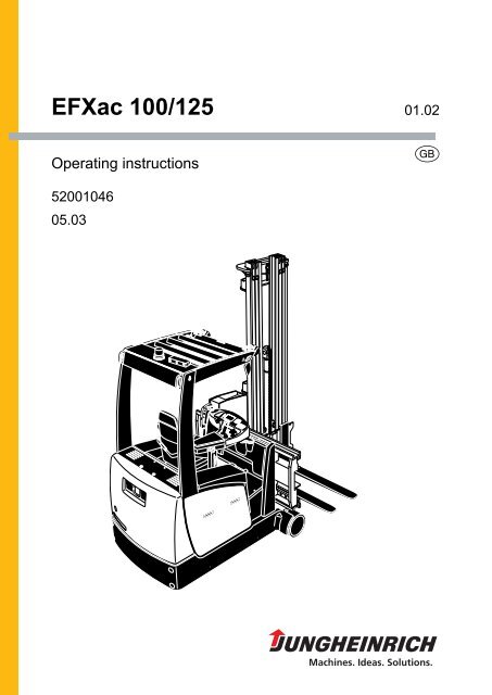
BTruck description1 Application descriptionThe <strong>EFXac</strong> <strong>100</strong>/<strong>125</strong> is an electric three-way lift truck which picks up, transports, andlifts its load outside the wheelbase. It can be used for internal goods traffic to stackand transport DIN 15142 pallets, DIN 15144 lattice box pallets, and other palletisedloads. If the <strong>EFXac</strong> <strong>100</strong>/<strong>125</strong> is used for assembly works with an according workingplatform, the load carrying unit must be supplied or approved by the manufacturer.For optimisation of the turnaround performance the truck can be operated diagonally,i. e. that travelling and lifting is possible simultaneously.The load fork can be designed for different load units. In case of the swivel/traversefork the distance between the fork arms is adjustable.For operation in aisles the <strong>EFXac</strong> <strong>100</strong>/<strong>125</strong> can be either be equipped with a railguidance system (RG) or inductive guidance system (IG). The driver can fullyconcentrate on his stacking work. Simultaneous travel and lifting is enabled in aisles.The activation is triggered by aisle detection sensors. Outside aisles the <strong>EFXac</strong> <strong>100</strong>/<strong>125</strong> can be freely moved, partly at restricted travel speeds depending on certain liftingheights.The racking systems must be suitable for the <strong>EFXac</strong> <strong>100</strong>/<strong>125</strong>. The safety distancesrequired and prescribed by the manufacturer (e. g. prEN 1726-2 item 7.3.2) must bestrictly observed. The ground must comply with DIN 15185. For the rail guidancesystem (RG) the aisles must be equipped with guide rails.Vulkollan guide rollers screwed to the truck chassis guide the truck between the guiderails.For the inductive guidance system (IG) a guide wire must be installed in the ground,and the signals from the guide wires are received by sensors at the truck chassis andprocessed in the truck computer.Definition of the travel directionThe following definitions are made for the indication of the travel direction:leftdrivedirectionloaddirectionright1102.GBB 1
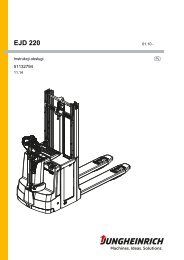
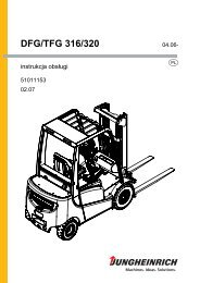
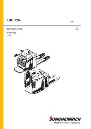
2 Description of assembly groups and functions116 17234155678910111214131102.GBB 2
Item Designation1 t Lifting mast2 t Supply lines3 t Load chains4 t Lifting cylinder5 t Boom6 t Fork arm carriage7 t Lateral traversing frame8 o Load sensor9 o Storage location sensor10 t Load wheel11 o Guide rollers (only for rail guidance)12 t Battery compartment13 t Traction compartment14 o IG sensors (only for inductive guidance)15 t Driver seat16 t Overhead guard17 o Working lightst = Series equipment o = Optional equipment1102.GBB 3
2.1 TruckChassis:The robust truck chassis is a skeleton construction. All enclosures are removable orcan be opened by hinges, thus providing excellent accessibility to all units and forservicing the battery. The truck's width, measured across the load wheels, can beadjusted to the respective requirements of the warehouse. Load axle widths of 1,210through 1,650 mm are available.Wheels:The load wheels are mounted on a cantilever axle. The bearings are constructed withtaper roller bearings, which allows problem-free adjustment and very easy wheelchange.Drive system:Arranged in standing configuration, heavy-duty three-phase AC motor(asynchronous) delivering 4.4 kW (S2 60 min). The motor is directly screwed onto thesingle-wheel drive unit, thus providing problem-free and fast maintenance.Steering:Low-friction electrical three-phase steering. The handy and small steering wheel isintegrated into the operating panel. When mechanical rail guidance is used, the drivewheel is set to straight position by the push of a button. The position of the steeredwheel is indicated on the operating terminal. The steering angle is +/- 90°, providingexcellent manoeuvrability in confined dead-end aisles.When the inductive guidance mode is used, the steering is automatically taken overby the system and manual steering is not active.Load-carrying units:The truck is equipped with a swivel/traverse fork. The load can be picked up directlyfrom the ground and tiered and untiered on both sides of the rack aisle. All limitpositions for traversing and turning are dampened. For fast pallet handling thetraversing and turning motions can be executed in parallel by pushing a button.Optionally the truck can be equipped with special attachment devices. The swivel/traverse fork can be equipped with a fork adjusting device.Lifting mast:Optionally double or triple lifting masts with full free-lift. The precision profiles areconnected to each other by means of torsion-resistant and flexurally rigidcrossbeams. Thus, minimum swinging during tiering and untiering is achieved. Thehydraulic cylinders are located on the sides, providing a good through-view.1102.GBB 4
Driver position:The spacious, ergonomically designed driver position with comfort seat and theergonomically optimised arrangement of all operating elements allow non-tiringoperation of the truck by the driver. The driver seat is vibration-dampened and can beadjusted to individual body heights and weights. The operating panel with armrest isadjustable in height and lengthways. All functions for lifting and lowering, traversing,and turning are operated via a thumb-actuated lever. All operating conditions such as,for example, lifting height, battery charge condition, time of day, position of steeredwheel, etc., are indicated on the operating terminal.Lifting height preselection (o):With the lifting height preselection system the driver can select the required liftingheight using the keyboard. When the desired lifting height is reached, the liftingprocess is automatically terminated. The lifting height preselection system can beused both for tiering and untiering of the load and also for lifting and lowering. Thelifting height preselection system is designed for warehouse sections with differentracking heights.Hydraulic system:All hydraulic movements are carried out by a maintenance-free 9.5 kW three-phaseAC motor with flange-mounted, low-noise gear pump. The oil is distributed viasolenoid switching valves. The different required oil amounts are controlled via themotor speed. When lowering, the hydraulic pump drives the motor, which works as agenerator at that time (regenerative lowering). The energy generated by this processis fed back into the battery.Brakes:a) The truck is decelerated wear-free and smoothly by releasing the acceleratorpedal or switching to the opposite travel direction. Thus, energy is reclaimed inthe battery (service brake).b) Moreover, the truck can be decelerated by a brake pedal acting on hydraulicallyoperated drum brakes in the load wheels.c) The electromagnetic spring-pressure brake acting on the traction motor servesas parking and service brake during tiering and untiering operations.d) In inductively guided trucks a spring-loaded brake acting on the load wheels isadditionally applied. This brake acts only in emergency-stop situations.1102.GBB 5
3 Technical data - standard versionAIndication of technical data according to VDI 2198.Subject to modification and supplementing.3.1 Performance dataDesignation<strong>EFXac</strong><strong>100</strong>* Values with reference to data sheet of standard truck<strong>EFXac</strong><strong>125</strong>Q Carrying capacity (D = 600 mm) <strong>100</strong>0 <strong>125</strong>0 kgD Load centre distance 600 600 mmTravel speed with/without load (RG) 9 9 km/hinside the aisle* Lifting speed without load 0.41 0.41 m/s* Lifting speed with load 0.41 0.41 m/s* Lowering speed without load 0.42 0.42 m/s* Lowering speed with load 0.45 0.45 m/s* Acceleration time without load 5.74 5.82 s* Acceleration time with load 6.11 6.52 s1102.GBB 6
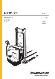
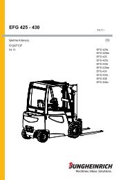
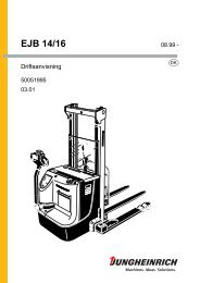
m1rl 8l 1l 21102.GBb7Astb12b5b1b2b6b14h2h6h1h3h4l 3 x yzm2l 6WaA st3B 7
3.2 Dimensions(Excerpt from datasheet)Designation <strong>EFXac</strong> <strong>100</strong> <strong>EFXac</strong> <strong>125</strong>h 1 Lifting mast height, retracted 1) 2805 2805 mmh 2 Free-lift 1) - - mmh 3 Lift 1) 4000 4000 mmh 4 Lifting mast height, extended 1) 4787 4787 mmh 6 Height above overhead guard 2277 2277 mmh 7 Seat height as per ISO 1190 1190 mmAst3 Width of aisle for pallet1740 1740 mm1,200 x 1,200 crosswaysb 2 /b 2 Overall width 1210/1650 1210/1650 mmb 5 Distance between forks, outside 850 850 mmb 6 Width across guide rollers 1650 1650 mml 1 Overall width without load 3186 3186 mml 2Length including back of fork 3000 3000 mm(without false edge)s/e/l Fork arm dimensions<strong>100</strong>x40x1200 <strong>100</strong>x40x1200 mmW a Turning radius 1848 1848 mmm 2 Ground clearance at centre of 85 85 mmwheelbaseDead weight with battery,without load5000 5280 kg1) 400 ZT mast, performance data measured for 400 ZT3.3 WheelsDesignation EFX ac <strong>100</strong> EFX ac <strong>125</strong>Tyres Tractothand 1 Tyre size, load wheels 144x295 144x295 mmd 2 Tyre size, drive wheel 343x140 343x140 mmNumber of wheels, front/rear 2/1x 2/1x(x = driven)b 10 Track width, load-side 1406 1406 mm1102.GBB 8
3.4 EN standardsContinuous sound level: EFX ac <strong>100</strong>/<strong>125</strong>: 69 dB(A)Aas per EN 12053 in analogy to ISO 4871.The continuous sound pressure level is a value that has been averaged according tothe guidelines of the standards and takes the sound pressure level during travelling,lifting, and idling into consideration. The sound pressure level is measured at the earof the driver.Vibration: EFX ac <strong>100</strong>/<strong>125</strong>: a w,zS = 0.48 m/s 2Aaccording to EN 13059.The swinging acceleration acting on the body in its operating position is, according tostandard regulations, the linear integrated, weighted acceleration in the verticalplane. It is determined by driving over bumps at a constant speed.Electromagnetic compatibility (EMC)AThe manufacturer confirms compliance with the limitvalues for electromagnetic emission and interferenceimmunity as well as testing of static electricity dischargeaccording to EN 12895 and the references to otherstandards contained therein.Modifications to electric and electronic components and their arrangement are onlyallowed with a permission in writing by the manufacturer.3.5 Conditions of useAmbient temperatureA- during operation +5 °C to +30 °C24-hour ambient temperature average:max. 25°Cmax. humidity in interior rooms 70%, no condensationFor permanent use below 0°C it is recommended to fill the hydraulic system with lowviscosityoil according to manufacturer information.1102.GBB 9
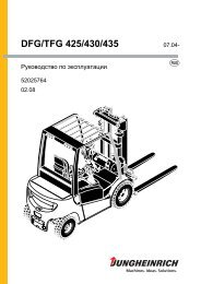
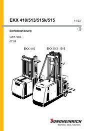
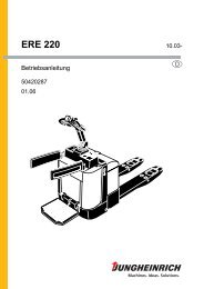
(mm)(mm)D (mm)D (mm)Q (kg)Q (kg)XxxXxxxxxxxxXxxxxxxXxxxxxxxxXxxxxxxXxxxxxxxxxxx Xxxxxxxxxxxx Xxxxxxxxx xxx xxxxxxxxXxxxxxxxXxxxxxxxxxXxxxxxxxxxxxxx xxxxxxxx4 Label positions and identification plates192021221820292328mV1,5 V27262524Item Designation18 Label “Observe operating instructions”19 Label, “Carrying capacity“20 Label, “Crane hook“21 Warning label “Laser radiation”22 Label “Do not step on or under load, danger of crushing”23 Identification plate24 Label, “Lifting point“25 Label “Fill in hydraulic oil”26 Label, “Emergency lowering”27 Warning label, “Electronics with low voltage”28 Label “No passengers allowed”29 Label “Toppling”1102.GBB 10
4.1 Truck identification plate30423132333435XxxXxxxXxxxxxxXxxxxxxxxXxxxxxxxxXxxxxxxxxxXxxxxxxxxXxxxxxxxxxXxxxxxxXxxxxxXxxxxXxxxXxxxxxXxxxxxXxxxxxxxxxxxxxxxxxxXxxxxxxxxxxxxxxxxxkgXxxxxxxxxxxxxxxxxmmXxxxxxxxxxxxxxxxxxxkgXxxxxxxxxxxxxxxxxxxxxxxxxxxxxVXxxxxxxxxxxxxxxxxkWxxxxxxxxkgXxxxxxxxxxxxxxxxXxxxxxxxxxxxxxxxxx36 3741403938Item Designation Item Designation30 Type 37 Driving power31 Serial no. 38 Customer No.32 Rated carrying capacity in kg 39 Min./max. battery weight in kg33 Battery: Voltage in V 40 Dead weight without battery in kg34 Manufacturer 41 Year of manufacture35 Order No. 42 Manufacturer's logo36 Load centre distance in mmIn the event of queries relating to the truck or spare part orders, please state the serialNo. (31) of the truck.4.2 CapacityThe label (19) indicates the carrying capacity (Q in kg) of the truck in dependence ofload centre distance (D in mm) and lifting height (H in mm) in tabular format.6(mm)Q (kg)19D (mm)(mm)Q (kg)D (mm)1102.GBB 11
B 121102.GB
CTransportation and commissioning1 TransportDepending on the overall height of the lifting mast and the local conditions, transportcan be performed in two different ways:m– Upright, with lifting mast mounted (for low overall height)– Upright, with lifting mast and traversing frame dismounted (for large overall height)The assembly of the truck on site, commissioning the truck and instructing the drivermust be carried out by personnel trained and authorised by the manufacturer.2 Transportation by cranemUse only hoisting equipment with appropriate carrying capacity (refer to the truck IDplate for truck weight, see chapter B). Observe additional battery weight!mm– Park and lock the truck (refer to chapter E).– Craning points are on the frame front wall (with the mast installed or removed) andon the eyes on the overhead guard.Attach the crane hoisting equipment at the lifting points in such a way that it cannotslip for any reason!The crane hoisting gear must be attached in such a way that it cannot damage anyattached components or the overhead guard during lifting.1102.GBC 1
4 Initial operationmThe truck may only be operated with the prescribed battery! Rectified alternatecurrent will damage the electronic components. Cables connected to the battery(trailing cables) must be less than 6 meters in length.In order to prepare the truck for work following delivery or transportation, the followingoperations must be performed:– If necessary, install and charge battery (refer to chapter D).– Commission the truck as detailed in chapter E.1102.GBC 4
D Battery - Servicing, recharging,replacement1 Safety regulations governing the handling of lead-acid batteriesThe truck must be parked and rendered safe before any operations on batteries areundertaken (refer to chapter E).Servicing staff: Recharging, servicing and replacing of batteries must only beperformed by qualified personnel. The instructions contained in this operatingmanual, and the instructions of the manufacturer of the battery and of the batteryrecharging station, must be observed when performing the above operations.Fire protection measures: Smoking and naked flames are not permitted whenhandling batteries. No inflammable substances or spark-generating materials mustbe present or stored within a distance of 2 meters of the truck parked for batteryrecharging. The location must be well ventilated and fire fighting equipment must bekept ready.Servicing of batteries: The battery cell screw caps must be kept dry and clean.Terminals and cable shoes must be clean, lightly greased with pole grease and mustbe securely tightened. Batteries with bare terminal posts must be covered using anon-skid insulating mat.mfmfDisposal of the battery: Batteries must only be disposed of as stipulated in thenational environmental protection regulations or waste disposal provisions. Themanufacturer’s specifications for the disposal must be heeded.Before closing the battery hood, make sure that the battery cable cannot bedamaged.Batteries contain dissolved acid which is toxic and caustic. For this reason, protectiveclothing and goggles must be worn whenever work is undertaken on batteries. Avoidphysical contact with battery acid.If clothing, skin or eyes accidentally come into contact with battery acid, liberally flushthe affected parts with clean water. Consult a doctor when skin or eyes come intocontact with battery acid. Spilled battery acid must be immediately neutralized.Only batteries with closed tray may be used.Battery weight and dimensions have considerable influence on operational safety ofthe truck. Changing the battery equipment is not permitted without prior approval bythe manufacturer.1102.GBD 1
2 Battery typesDepending on the truck version, the vehicle is supplied with different battery types.The following table shows the standard combinations, indicating the capacity:Battery typeTruck type48V 5PzS 550 Ah <strong>EFXac</strong> <strong>100</strong>48V 6PzS 660 Ah <strong>EFXac</strong> <strong>125</strong>The battery weights can be seen on the battery identification plate. When batterieswith a lower weight are used, a battery compensation weight must be installed.2.1 Exposing the batteryPark and lock the truck (refer to chapter E).– Swing up the battery hood (1).1ffBe careful when opening or closing the battery hood.Before commissioning the truck, make sure to return all coverings and connectionsto the normal operating state.1102.GBD 2
3 Charging the batteryffPark and lock the truck (refer to chapter E).– Turn key switch to “0” (zero) and push the EMERGENCY OFF button.– Fully open the battery cover.Connecting and disconnecting the battery plug and socket is only permitted with thetruck and charger switched off.ffff– Unplug battery connector.– If necessary, remove the rubber insulating mat from the battery.As hazardous gases are produced during the charging operation, sufficient fresh airsupply must be ensured.No metal objects must be placed on the battery. Prior to starting the rechargingoperation, check all cable connections and plugged connections for visible damage.– Connect charging cable of the battery charging station to the battery plug.– Switch on the charger.– Recharge the battery observing the instructions provided by the battery supplierand by the battery charger supplier.All safety instructions as provided by the battery supplier and battery charger suppliermust be strictly observed.Only chargers prescribed by the battery supplier may be used.1102.GBD 3
4 Removing and installing the batteryffffOnly batteries with isolated cells and insulated terminal connections are allowed.When replacing the battery, make sure only to use the same type as replacement.Additional weights must not be removed and their position not changed.The truck must be parked on a horizontal surface, so that the battery cannot roll outby itself when the battery securing device is removed.Connecting and disconnecting the battery plug and socket is only permitted with thetruck and charger switched off.When changing/installing the battery, make sure that the battery is seated firmly inthe battery compartment.f– Turn key switch to “0” (zero) and push the EMERGENCY OFF button.– Expose the battery (see section 2.1).– Unplug battery connector.– Lift out the frame side walls (2).– Loosen and remove the battery safety device (3).– Pull out the battery to the side onto the battery trolley provided.Replacing the battery is done in reverse order.After replacing the battery, check all cable and plugged connections for visibledamages and before recommissioning check that:– the battery safety device is inserted and tightened,– the battery cover is fully closed.231102.GBD 4
5 Check battery condition, acid level, and acid concentration– The warning notes of the battery manufacturer must be observed.– Check the battery housing for cracks and leaking acid.– Remove oxidation residue at the battery terminals and grease the terminals withacid-free grease.– Unscrew the plugs and check the acid level.The acid level must be at least 10-15 mm above the plates’ top edge.– Check the acid concentration according to the battery manufacturer’s instructionsusing an acid pipette and screw in the plugs again when finished.– If required, recharge the battery.6 Battery discharge indicatorAfter turning the key in the keyswitchclockwise and pulling the EMERGENCYOFF switch, the battery charge indicatorshows the remaining capacity. If theremaining capacity is at 30% the displayflashes. Below 20% capacity the lift cutoffis activated.Once the lift cut-off has been activated,it is only re-enabled at a battery capacityof 40%.1102.GBD 5
D 61102.GB
EOperation1 Safety regulations governing the operation of the fork lift truckDriving permission: The fork lift truck must only be operated by persons who havebeen trained in the operation of trucks, who have demonstrated to the user or hisrepresentative their capability of moving and handling loads, and who have expresslybeen charged by the user or his representative with the operation of the truck.Rights, duties and conduct of the driver: The driver must be: informed of his rightsand duties; trained in the operation of the fork lift truck; and familiar with the contentsof these operating instructions. All necessary rights must be granted to him.If the fork lift truck can be used in the pedestrian-controlled mode, the driver mustwear safety boots when operating the truck.Prohibition of unauthorised use: The driver is responsible for the fork lift truckduring working time. He must forbid unauthorised persons to drive or operate the forklift truck. The transport or lifting of persons is forbidden.Damage and defects: Damage or defects noted on the fork lift truck or on theattachments must immediately be brought to the notice of the person in charge. forklift trucks that cannot be safely operated (e.g. due to worn tyres or defective brakes)must not be used until they have been properly repaired.Repairs: Without specific training and express authorisation, the driver is not allowedto perform any repairs or modifications on the fork lift truck. Under no circumstancesmust the driver change the setting of switches or safety installations or render themineffective.fDanger area: A “danger area” is considered to be the area within which persons areendangered by the travelling or lifting movements of the fork lift truck or its load liftingdevices (e.g. fork or attachments), or by the loads being transported. This alsoincludes the area within reach of falling loads or falling / lowering truck attachments.Unauthorised persons must be asked to leave the danger area. The driver must givea warning signal whenever a situation presenting danger to persons might develop.The fork lift truck must immediately be brought to a standstill if persons, althoughasked, do not leave the danger area.Safety devices and warning labels: The safety devices, warning labels and warningnotes described in the present operating instructions must always be heeded.1102.GBE 1
2 Description of operating and display elements1 2 3 4111098756Item Operating or display Functionelement1 Steering wheel t Steers truck in desired direction2 Display t Displays operating information and warnings3 Lifting heightt Range selectionpreselection (o):4 Lifting heightt Shelf selectionpreselection (o):5 Travel direction switch t Selects desired travel direction6 Key switch t Switches control voltage on and off7 EMERGENCY OFFswitch8 Pushbutton “Warningsignal”t The power circuits are interrupted, all movingfunctions switch offt When actuated, triggers warning signal9 Hydraulics control knob t Lifting and lowering, traversing and swivelling10 Pushbutton “Traversingfork arm carriage”11 Pushbutton “Traversingload-carrying unit”t Switches the hydraulics control knob to function“Traversing fork arm carriage”t Switches the hydraulics control knob to function“Traversing load-carrying unit”t = Series equipment o = Optional equipment1102.GBE 2
2.1 Foot-operated elements121314Item Operating or displayelement12 Dead man pushbutton(foot-operated switch)Functiont Disengage the parking brake.When actuated, disengages the spring-loadedbrake and releases the travel motion. Releasingthe dead man pushbutton results in immediatedeceleration of the truck to standstill.13 Brake pedal t Actuates the load wheel brake14 Accelerator pedal t Continuous control of travel speedt = Series equipment o = Optional equipment1102.GBE 3
2.2 Operating and display elements at the displaySymbols in the upper sectionItem Symbol Operating anddisplay element15 Pushbutton “Quitsubmenu”tFunctionJumps back from the submenu to thehigher level menu16 Display “Servicerequired / fault”tLights up when service is required or amalfunction has occurred17 Display of possibletravel speed:SnailRabbittInchingMaximum speed18 Display “STOP” t Lights up when the foot-operateddeadman key is not pressed; driving isimpossible.1102.GBE 4
Item Symbol Operating anddisplay element19 Display“Guide wire detected”IGFunctionSensors that have detected the guidewire are shown with dark background20 Display “Parkingbrake ON”t Lights up when the parking brake hasbeen engaged21 Steering angle display(changes to the guidesystem display)tRGIGShows the current steering angle inrelation to the centre positionAfter tracking-in, centre position isshown permanentlySteering angle display extinguishes andis replaced by guide wire symbols22 Display “Time of day” t Displays the time of day23 Display “Operatinghours”t Shows the number of operating hourssince initial commissioning24 Battery dischargeindicatort Shows the charging condition of thebattery (remaining capacity in percent)25 Symbolic display t26 Function keys t Activates and confirms the functionassociated with the key1102.GBE 5
Symbols and pushbuttons in the lower sectionThe pushbuttons (26) under the respectively shown symbols (25) activate oracknowledge the functions associated with them. The symbol is then shown with darkbackground.Symbol Operating or display FunctionelementWarningsDisplay “Height-dependentlift limitation”o Appears when the height-dependent lift limitationhas been activatedPushbutton “Overrideheight-dependent lift limitation”Overrides the height-dependent lift limitation(display shown with dark background);the maximum clearance must be observedDisplay “Lowering limitation”o Indicates that the automatic lowering limitationwas triggeredPushbutton “Overridelowering limitation”Overrides the lowering limitation, controlwith hydraulics control knobDisplay “Drive cut-off” o Indicates that the automatic, height-dependentdrive cut-off has been activatedPushbutton “Overridedrive cut-off”Overrides the automatic height-dependentdrive cut-offDisplay “Personnelprotection facility” (PSS)o Indicates that the personnel protection facilityhas detected persons/objects in the aisle,the truck is decelerated.Pushbutton “Personnelprotection facility” (PSS)Display “Call warningssubmenu”Quit submenu “Warnings”oOverrides the protection function and enablesinching with sufficient safety distance tothe obstacle.If a personnel protection facility is installed,you must observe the separate operating instructions.Indicates that several warnings (e. g. slackchainsafety device, height-dependent liftcut-off) have been issued.Displays individual warnings1102.GBE 6
Symbol Operating or displayelementGuidance systemsPushbutton “GuidanceON” (dark background,when active)tRGFunctionIndicates forced guidance in the aisle:Display “Rail guidance”(Drive wheel set straight)Pushbutton“Guidance ON”Pushbutton “Selectfrequency 1” (and otherfrequencies in the sameway)(Submenu“Guidance ON”)Pushbutton “Select frequency1” (and other frequenciesin the sameway)Fork operationDisplay “Toggle menusynchronous turning”Pushbutton “Togglemenu synchronous turning”Display “Synchronousfork left turn”Pushbutton “Synchronousfork left turn”Display “Synchronousfork right turn”Pushbutton “Synchronousfork right turn”Display„2. Stacking depth”Pushbutton„2. Stacking depth”IG Indicates that inductive guidance is activeRG Sets the drive wheel in straight positionIG Activates the tracking-in process (and frequencyselection for multi-frequency)o Indicates that guidance is possible via frequency1IGttActivates guidance via frequency 1 (submenuopens automatically after pushing for1 second)Toggling the display menu to the “Synchronousturning” functionsActivates synchronous turning menu togglingIndicates that synchronous left turning/righttraversing of the fork is possibleActivates left turning of the fork and simultaneouslycontrols right traversing of the boomby using the hydraulics control knobIndicates that synchronous right turning/lefttraversing of the fork is possibleActivates right turning of the fork and simultaneouslycontrols left traversing of theboom by using the hydraulics control knobIndicates that the 2nd stacking depth isenabledActivates the 2nd stacking depth, controlledby hydraulics control knob1102.GBE 7
Symbol Operating or displayelementFork arm adjustmentDisplay “Symmetricalfork arm adjustment”Pushbutton“Symmetrical fork armadjustment”oFunctionIndicates that the fork arm adjustment canbe operatedActivates fork arm adjustment forsimultaneous operation of the hydraulicscontrol knob,Turn right = fork arms to inside;Turn left = fork arms to outside;t = Series equipment o = Optional equipmentRG = Rail GuidanceIG = Inductive Guidance1102.GBE 8
Additional symbol displaysTurn cut-off overrideDateCurve area“Tracking-in”“Wire-guided”“Deviation from guide wire”Main lift ref., height indicationAntenna load directionField detectedAntenna load direction and antenna centreField detectedAntenna load direction, antenna centreand antenna drive direction, field detectedAntenna centreField detectedAntenna drive direction and antenna centreField detectedAntenna drive directionField detectedActuate foot switchReference drive - lowering1102.GBReference drive completed, height indicationE 9
Reference drive - liftingWorking lights overhead guardWorking lights load-carrying unitMenu button lights, fanSpotlightsWarning lampBack to truck functionsSet clockHours minusHours plusMinutes minusMinutes plusFanToggle to submenuSide shift and fork arm adjustmentPersonnel protection facility active, flashing not active1102.GBE 10
Personnel protection facility forced braking, acknowledge parkingrequiredSide shiftLoad-carrying unit in transport positionTurn steering wheel left to drive straightTurn steering wheel right to drive straightStraight travelDrive wheel position indicator2. Stacking depthEnd-of-aisle safety device override1Zone 1 to zone 7, or A to HClamp menu buttonOpen clampClose clampTravel direction indicator drive direction1102.GBTravel direction indicator load directionE 11
Display symbol assignment1102.GBE 12
Symbol allocation displayTTime of dayheightindicationOperating hours1102.GBE 13
3 Starting up the truckfBefore starting or operating the truck, or before lifting any loads, the driver has tomake sure that nobody is within the danger area.The operating condition of the truck after switching on is indicated by the symbols inthe display.3.1 Checks and operations to be performed before starting daily work– Check the entire truck outside for obvious damages or leaks.– Check battery mounting, cable connections for damages and tight seat.– Check battery plug for tight seat.– Check overhead guard for damages.– Check load-carrying unit for noticeable damages such as cracks, bends or heavyabrasions on load fork.– Check condition of fork arm locks and stop bolts to prevent pushing the fork armsout to the side.– Check load wheels for damages.– Check whether the load chains are tensioned uniformly.– Check whether all safety devices are operational and function properly.– For rail guided trucks, check guide rollers for concentric running and damages.– Check function of service brake and parking brake.– Check the brake fluid level.– Check function of end-of-aisle safety device.– Check braking distance when EMERGENCY OFF switch is actuated during travel.– Check tilting safety for firm seating.1102.GBE 14
3.2 Mounting and descending from the truckWhen mounting the truck anddescending from the truck, firmly grabthe handle (27) at the driver seat.Descent from the truck only backwards.273.3 Adjusting the driver seatATo achieve optimum seat cushioning the driver seat must be adjusted to the driver’sweight. Adjustment range of seat cushioning: 50 kg to 130 kg.Adjusting the seat cushioning:– Remove any load from driver seat.– Pull seat cushioning setting lever (29)in arrow direction to the limit and guideback again.The prior weight setting is reset to theminimum value.– Pull seat cushioning setting lever (29)in arrow direction until thecorresponding weight is indicated onthe driver seat weight display (28) andguide the setting lever back again.– Sit on the driver seat.272829 30311102.GBE 15
Adjusting the backrest:– Pull up the backrest adjustment (27) and set the backrest tilt to the desired position.– Allow backrest adjustment to latch.Adjusting the seating position:f– Pull driver seat locking lever (30) outward and set driver seat to the desired seatingposition by sliding it forward or backward.– Allow locking lever to latch again.The driver seat locking must be securely latched in the adjusted position. The driverseat setting must not be modified while travelling.Adjusting the armrest:– Rotate the handwheel (31) on the armrest up or down until the desired position hasbeen reached.3.4 Safety seat beltfPut on the safety seat belt every time before moving the industrial truck.The belt protects you from serious injuries.AffProtect the safety seat belt from dirt (e. g. cover up at standstill) and clean regularly.If the belt catch or retractor is frozen, let it thaw and allow to dry to avoid freezingagain.The drying temperature of the warm air must not exceed +60°!Modifications to the safety seat belt are not permitted!Increased risk through malfunctions.– Replace safety seat belts after an accident.– Use only original spare parts for retrofits and repairs.Damaged or non-functioning safety seat belts must be exchanged by authoriseddealers or in the subsidiary.1102.GBE 16
fManaging extraordinary situationsIf the industrial trucks is about to turn over, do notunfasten the belt and do not try to jump off thetruck under no circumstances.Jumping off increases the risk of sufferinginjuries!Correct behaviour:– Grip the steering wheel with both hands andsupport yourself with the feet.– Tilt body against falling direction.Instructions for using the safety seat beltfBefore starting the industrial truck, pullthe belt smoothly out from the retractor,pull it tight to the body over the thighsand latch it with the buckle.The belt must not be twisted when puton!When operating the industrial truck (e. g.travelling, lifting, lowering, etc.), sit backas much as possible, so that your backis leaning against the backrest.The automatic locking retractor allowssufficient freedom of shifting around onthe seat.1102.GBE 17
fAWhen sitting on the front edge of the seat, the belt is rolled out too long, thus providingnot enough protection.Use the belt to secure persons only.A– After use, push the red button and hold the latch with your hand while the belt isbeing retracted.The latch hitting the housing can trigger the automatic locking mechanism. In thatcase the belt cannot be rolled out.Releasing the block:– Pull the belt with increased force 10 to 15 mm out of the housing.– Allow belt to retract in order to release the automatic locking.The belt can now be rolled out again.3.5 Adjusting the operating panelThe operating panel can be adjusted inheight and laterally.Height adjustment:– Simultaneously grip operating paneland release lever (32).– Adjust operating panel to correctheight and retighten lever.Lateral adjustment:– Pull lever (33) upward.– Adjust operating panel to correctposition.– Allow lever to latch (33) again.33321102.GBE 18
3.6 Providing operational readinessf– Unlatch the EMERGENCY STOPswitch (7) by turning it.– Insert key into key switch (6) and turnclockwise.– Check proper function of warningfacility (horn) (8).– Check proper function of servicebrake and parking brake.– Perform reference drive of lifting mastfor height indicator adjustment.If any undesired travel or lifting motionoccurs, immediately actuateEMERGENCY OFF switch.3.7 Reference drive876A reference drive must be performed every time before putting a truck into service,i.e. when the key switch (6) was set to “OFF”.– Turn key switch (6) to “ON”– Step on the foot switch (12)– Swivel hydraulics control knob (9) to “Lifting” until the lift switches off automatically(lifting bypass is indicated), then fully lower it again.This is the only way the control system enables all movements of the truck at fullspeed, and the height preselection is adjusted.Lifting and lowering is indicated by the symbols:Reference drive: Lift the main liftReference drive: Lower the main lift1102.GBE 19
4 Operation of the fork lift truck4.1 Safety regulations applicable when operating the truckDriving lanes and work areas: Only such lanes and routes that are speciallyallocated for truck traffic must be used. Unauthorized persons must stay away fromwork areas. Loads must only be stored at places specially provided for this purpose.Driving conduct: The travelling speed must be adapted to the prevailing localconditions. The truck must be driven at slow speed when negotiating bends or narrowpassages, when passing through swing doors and at blind spots. The driver mustalways observe an adequate braking distance between the fork lift truck and thevehicle in front and he must be in control of his truck at all times. Sudden stopping(except in emergencies), rapid U-turns and overtaking at dangerous or blind spots isnot permitted. It is forbidden to lean out of or reach beyond the working and operatingarea.Visibility: The driver must look in the direction of travel and must always have a clearview of the route ahead. When loads blocking the view are carried, the fork lift truckmust be driven with the load at the rear. If this is not possible, a second person mustwalk in front of the fork lift truck to give suitable warnings.Negotiating slopes and inclines: Negotiating of slopes and inclines is permittedonly when they are recognised lanes, when they are clean and non-slipping, andwhen the technical specification of the truck permits safe driving on such slopes orinclines. Loads must always be carried at that end of the truck facing uphill. U-turns,cutting obliquely over slopes or inclines and parking of the fork lift truck on slopes orinclines is not permitted. Inclines must only be negotiated at slow speed, with thedriver ready to brake at any moment.Use of lifts and driving on loading platforms: Lifts and loading platforms must onlybe used if they are of adequate load bearing capacity, if suitable for driving on, and ifauthorised by the user of the truck for truck traffic. The fork lift truck driver has tosatisfy himself accordingly before driving into lifts or on to loading platforms. The truckmust enter lifts with the load in front and must take up a position which does not allowit to come into contact with the walls of the lift shaft.Persons riding in the lift together with the fork lift truck must only enter the lift after thefork lift truck has come safely to a standstill, and must leave the lift before the fork lifttruck.Nature of the loads carried: Only loads that have been safely and correctly securedmust be carried. Never transport loads stacked higher than the top of the forkcarriage, or stacked higher than the guard grille.Towing trailers: The maximum trailer load given for the fork lift truck for braked and/or unbraked trailers must not be exceeded. The trailer load must be properly securedand must not exceed the dimensions permitted for the driving routes. After attachingthe trailer but before starting driving, the driver must check that the trailer attachmentis secured against detachment. Towing fork lift trucks must be operated in such amanner that safe driving and braking of the truck and the trailer is guaranteed for alldriving movements.1102.GBE 20
Travelling in aisles: Before driving into an aisle the driver must check whetherpersons or other industrial trucks are in this aisle. If this is the case and if no sufficientmeasures to protect personnel or to avoid collision with other industrial trucks exist,the driver must not drive into this aisle.A special source of danger in aisles are objects that project from the racking.Therefore, always watch the full height of the aisle.The floor must be clear of any obstacles. The floor surface must be clean in order toachieve sufficient traction.If an aisle is equipped with inductive guidance and the guidance system is defectiveor switched off, only trained and authorised personnel may drive the truck out of theaisle.Flattening of wheels: When the truck is parked for extended periods, the runningsurface of the tyres will flatten. However, this does not affect the travel safety orstability of the truck as the flattening will disappear after travelling for a while.1102.GBE 21
4.2 Driving, steering, brakingEMERGENCY OFF– Push the EMERGENCY STOP switch(7) down.All moving functions switch off.The function of the EMERGENCYOFF switch must not be impaired byany objects placed in the switch area.7DrivingThe truck can be driven in one of three operating modes:Free driving on the apron, driving in aisles with inductive or rail guidance.The operating mode used depends on the guidance system of the racking systemthat the truck is travelling in.For travel operation the foot switch must be constantly pressed. Releasing the footswitch will initiate forced braking.fDriving on the apronThe travel paths must be free of obstacles. Adapt the travel speed to the conditionsof the travel paths, the working area, and the load.A– Lift the load-carrying units so that theload forks are clear off the ground.– Set travel direction switch (5) to thedesired travel direction– Actuate foot switch (12) and carefullypush down accelerator pedal (14) untilthe desired travel speed has beenreached.The travel speed can be controlledcontinuously. The more the acceleratorpedal is pressed down, the faster will bethe travel speed.512141102.GBE 22
SteeringOutside of aisles the truck is steered bymeans of the steering wheel.The drive wheel angle is indicated in thedisplay (21).ABrakingThe braking behaviour of the truck is mainly dependent on the ground structure. Thedriver must consider this when handling the truck.The truck may be braked in four ways:– by means of the service brake– by means of brake pedal– by means of parking brake– by means of EMERGENCY OFF switchBraking by means of service brakeThe truck is decelerated in wear-free manner by releasing the accelerator pedal orswitching to the opposite travel direction.Braking by means of brake pedalBy actuating the brake pedal the truck is decelerated by means of the hydraulic drumbrake in the load wheels.Braking by means of the parking brakeThe truck is decelerated by releasing the foot switch.Braking with EMERGENCY OFF switchThe truck is strongly decelerated to standstill by actuating the EMERGENCY OFFswitch.mIn inductively guided trucks a spring-loaded brake acting on the load wheels isadditionally applied.The EMERGENCY OFF switch must only be actuated in emergency situations.1102.GBE 23
mAATravelling in aislesUnauthorised personnel and through-traffic for personnel is not allowed in aisles(travel paths for trucks in racking systems without safety distance for oncomingpersons(as stipulated by VBG636§28, section 1). Such working areas must bemarked accordingly. Existing protection devices at trucks or the racking system forpreventing dangerous situations and protecting personnel must be checked on a dailybasis (as per DIN 15185-2). Such devices must not be rendered unusable, must notbe misused, maladjusted, or removed. Malfunctions on safety devices must bereported and repaired immediately.Before driving into an aisle the driver must check whether persons or other trucks arein this aisle. Only free aisles may be entered. If personnel is in the aisle, the operationmust be stopped immediately.Driving into aisles is only allowed with trucks that have been designed for thisoperation. If an aisle is equipped with an inductive guide wire system and theinductive guide wire system is defective or switched off, the truck may only be drivenout of the aisle at inching speed.Diagonal travelDiagonal travel is possible bysimultaneously actuating hydrauliccontrol lever (9) and stepping downaccelerator pedal (14) (simultaneoustravelling and lifting or lowering).914fATrucks with rail guidanceThe rail height must be at least 40 mm.Rail-guided trucks are equipped with sensors that activate the aisle detection whenentering the rack aisles.– Position the truck at reduced speed in front of the aisles, so that it is aligned withthe aisle and its markings.Observe the signs affixed to the travel paths.– Slowly drive truck into the aisle.Observe that the guide rollers of the truck fully thread into the guide rails of the aisle.1102.GBE 24
– Push “Guidance” (26) button.– The drive wheel is automatically setstraight and the indicator lamp“Guidance ON” (25) is inverted.Manual steering is out of operation.– Continue to drive the truck at thedesired speed in the aisle.fffTrucks with inductive guidanceWhen starting or continuing to travel after switching off inductive guidance you mustobserve the position of the drive wheel, as manual steering is active again.If an inductively forced guided truck is switched off, the inductive guidance will nolonger be active when the truck is switched on again. Danger of accidents! When thetruck is not braked, a warning signal is issued and the speed is reduced. Presspushbutton (26) to activate inductive guidance again (indicator lamp “Inductiveguidance active”(25) lights up) and track-in the truck again.During the tracking-in procedure the truck’s rear section might break out of line undercertain circumstances if the front sensor (36) has already crossed the guide wirebefore the button “Inductive guidance ON” has been pushed.– Drive the truck (34) diagonally atreduced speed towards the guide wire(35).When tracking-in, the truck must not bein parallel to the guide wire and theapproaching angle should be between10° and 35°.36The tracking-in procedure should beperformed in load direction, since therequired time and distance are smallestin this direction.– When near the guide wires of theinductive guidance system, actuatepushbutton (26).The indicator lamp “Inductive guidanceactive” (25) illuminates.3534When the guide wire is reached, thetruck is automatically guided.The tracking-in procedure is automatically executed at reduced travel speed whenthe guide wire is reached. The display for “Tracking-in” (21) lights up. The auditivetracking signal is sounded.1102.GBE 25
The inductive forced steering takes oversteering of the truck and turns it to theguide wire.After the truck is exactly tracking theguide wire the tracking-in procedure iscompleted. The display (21) changes to“Wire-guided”. The tracking-in signal isno longer sounded. The truck is nowforce-guided.The maximum travel speed is enabled.fTo leave the guide wire the pushbutton(26) for inductive forced steering mustbe actuated.Switching over to manual steering may only be performed when the entire truck hasleft the aisle.If during inductive guidance of the truck the guiding antenna leaves the predefinedlevel area of the guide wire, an emergency stop is initiated immediately.1102.GBE 26
4.3 Lifting - lowering - traversing - swivellingfDanger of pinching when swivelling or shifting the fork arms.No personnel is allowed in the danger zone when swivelling, shifting, or synchronousturning the load-carrying unit.Lifting - lowering (load-carrying unit)AA– Turn hydraulic control knob (9)clockwise = liftingcounter-clockwise = loweringThe lifting and lowering speed isproportional to the hydraulic controlknob deflection.The maximum lifting speed is achieved,when carrying position swivel/traverse isindicated in the display.Lowering is only possible when the truckis ready for operation.9Traversing (boom)– Do not actuate the foot switch.– Actuate pushbutton (11) (= Traversingload-carrying unit).– Simultaneously turn hydraulic controlknob (9).Turning clockwise =Traversing rightTurning counter-clockwise =Traversing leftThe traversing speed is proportional toproportional to the hydraulic controlknob deflection.1191102.GBE 27
Swivelling (fork arm carriage)– Do not actuate the foot switch.– Actuate pushbutton (10)(= press Swivel fork arm carrier).– Turn hydraulic control knob (9).Turning clockwise= Swivelling rightTurning counter-clockwise= Swivelling leftThe swivelling speed is proportional toturning the hydraulic control knob.109fASimultaneous traversing and swivelling of the fork arm carriage (manually)Danger of pinching when swivelling or shifting the fork arms.No personnel is allowed in the danger zone when swivelling, shifting, or synchronousturning the load-carrying unit.When shifting the load-carrying unit the fork arm carriage is swivelled.The turning speed is not variable.The traversing speed is proportional to the deflection of the hydraulic control knob.– Do not actuate the foot switch.– Actuate pushbutton (38).– Turning hydraulic control knob (9)counter-clockwise = Swivelling thefork arm carriage to the right andtraversing the boom to the left.– Actuate pushbutton (37).– Turning hydraulic control knob (9)counter-clockwise = Swivelling thefork arm carriage to the left andtraversing the boom to the right.373891102.GBE 28
4.4 Picking up, transporting, and putting down load unitsmBefore picking up a load unit the driver must make sure that it has been correctlypalletised and does not exceed the permissible capacity of the truck. Observecarrying capacity diagram!f– Manually adjust the fork arms or reposition hydraulically, if necessary (o).The fork arms must be adjusted in such a way that both have the same distance tothe outside edges of the fork arm carriage and the load centre is centred between thefork arms. Fork arms must be locked!Picking up a load sidewaysf– Carefully approach the load to bepicked up in parallel to the load.– Do not actuate the foot switch.– Lift the load-carrying unit respectivelylower to the proper height with respectto the load, so that the fork arms canbe inserted under the load withoutdamaging it.Lifting persons is prohibited.f– Carefully insert the load-carrying unitunder the load until it makes contactwith the back of the fork.The fork arms must be inserted into theload with their full length.– Lift the load-carrying unit slightly sothat the load is clear off the ground.– Shift load-carrying unit in transportposition.AfThe swivel/traverse fork must beswivelled crossways to the traveldirection and must be positioned in leftrespectively right transport position.Make sure that nobody steps under thelifted load.– Once in the apron, lower the load totransport height.The picked up load can now betransported.1102.GBE 29
Picking up a load with swivel/traverse fork from the frontAfffAA– Swivel the swivel/traverse fork 90°away from the transport position andtraverse to the centre axis of the truck.The swivel/traverse fork is nowpositioned in travel direction.– Lift the swivel/traverse forkrespectively lower to the proper heightwith respect to the load, so that thefork arms can be inserted under theload without damaging it.Lifting persons is prohibited.– Carefully move the truck into thedirection of the load until the loadmakes contact with the back of thefork.The fork arms must be inserted into theload with their full length.– Do not actuate the foot switch.– Lift the swivel/traverse fork slightly sothat the load is clear off the ground.– Step on the foot switch.– Drive the truck carefully in drivedirection only as far until the load isfree.This operating mode is only allowed atthe stack!Make sure that nobody steps under thelifted load.– Do not actuate the foot switch.– Lower the load.– Move the swivel/traverse fork intransport position.The swivel/traverse fork must beswivelled crossways to the traveldirection and must be positioned in leftrespectively right transport position.The picked up load can now betransported.Rotating loads > 500 kg at heights above2 m is not possible.1102.GBE 30
ffPicking up and setting down a load in the aisleIn aisles the operator must pay specialattention. The aisle must not be enteredwhen persons or another truck is in theaisle. Also during the stacking procedurethe driver must make sure that personsor trucks do not enter the aisle. If this isthe case the truck must be stoppedimmediately and a warning signal mustbe issued.– Position the truck preciselyhorizontally and vertically in front ofthe rack shelf.– Pick up or set down the load (refer tosection “Picking up a load sideways”respectively “Setting down a load”).Special care must be taken whenworking at the first rack shelves, as thetruck is partly located outside the aisleand persons and trucks moving in thetravel range may be injured or damaged.AffTransporting loadsObserve clearance heights and widthsat doors and between racks.If the load is stacked high and obstructsthe view, a second person must bepresent for guiding.– Sensitively accelerate the truck andalways be prepared to apply thebrakes.Adapt the travel speed to the condition ofthe travel path and to the transportedload. Watch the traffic at intersectionsand passages and use the help of asecond person when negotiating unclearsections.1102.GBE 31
Setting down loadsfm– Carefully approach the storageposition with the truck.Before the load can be set down thedriver must verify that the storageposition is suited for the load(dimensions and carrying capacity).– Do not actuate the foot switch.– Lift the load-carrying unit until the loadcan be inserted into the storageposition without colliding.– Carefully push the load into thestorage position.– Carefully lower the load-carrying unituntil the fork arms are clear off theload.Avoid setting down the load heavily, inorder not to damage load and loadcarryingunit.– Carefully shift load-carrying unit out ofthe load.– Fully lower the load-carrying unit.4.5 Lifting height preselection (o):To pick up or set down loads at preselected storage locations, the truck must beadjusted to the warehouse facilities. The work required for this purpose may only becarried out by customer service.Storage location recognition (zones)The zones are entered via number keys or input keys F1 - F7.Picking up or setting down load in preselected storage locations with heightpreselection:– Drive truck into the corresponding aisle– Enter the shelf number.The shelf number is entered via the number keys.The shelf number can be entered as a single digit (1- 9) or two digits (01 - 64).The entry can be deleted with the “CE” key.If height “0” is entered for the selected shelf, the height preselection is not active.Depending on the parameter settings there are different operating methods to reachthe desired height:1102.GBE 32
OFFmanualsemi-automaticautomaticNo desired height set (desired height must approachedmanually).The hydraulic control knob must be actuated until thedesired height is reached.The hydraulic control knob must be actuated untilshortly before reaching the desired height.The hydraulic control knob must be tapped into thedesired direction, the desired height is thenautomatically approached.If another shelf is selected during the positioning process, this value is stored in abuffer and shown for approx. one second in the display. When the stacking cycle isfinished the shelf is automatically retrieved from the buffer.Depending on the variant the following variations are possible for the stacking cycle:1. Stacking cycle not active.2. Stacking and retrieving is predefined by the load sensor. The individual functionssuch as traversing, lifting, and lowering are performed by the driver. Afterreaching the respective end position the next work step can be carried out. Thedriver can select all hydraulic speeds.3. The hydraulic control knob must be held in the desired direction during the entirestacking process. The driver can control the stacking setpoint while stacking is inprogress.AfCareful stacking is thus possible with and without load while retracting occurswith a fixed setpoint.All automatic cycles can be interrupted by stepping on the foot switch.In case of danger actuate the EMERGENCY OFF switch.1102.GBE 33
4.6 Laser beam rack shelf indicator (o)The laser beam rack shelf indicator shows the correct position of the three-way truckwith respect to the rack shelf in travel direction.This device is a spot light that is mounted on the overhead guard.mThe correct position of the three-way truck with respect to the rack shelf has beenreached when the laser beam of a light hits the marking on the rack.Laser beam!Do not look into the beam!Laser Class 24.7 Safe parking of the truckfAWhen the truck is left, it must be parked in a secure manner, even when leaving thetruck for a short while only.Do not park the truck on slopes. Under special circumstances the industrial truckmust be secured, for example, by means of chocks.Select the parking location in such a manner that nobody can get caught on the forkarms.– Lower fork arms to the floor.– Move the swivel/traverse fork in transport position.– Set key switch to position “0” and remove the key.1102.GBE 34
5 TroubleshootingThis chapter allows the user to locate and eliminate simple malfunctions by himself.When trying to locate a fault, proceed in the order shown in the table.Fault Possible cause Remedial actionTruck does notmove– Battery connector notconnected– Check battery plug and plug in, ifnecessary–EMERGENCY OFF – Unlatch EMERGENCY OFF switchswitch pressed– Key switch in position – Set the key switch to position “I”“0”– Battery charge too low – Check battery charge, rechargebattery, if required– Foot switch not – Actuate foot switchactuated– Drive cut-off has been – Actuate pushbutton “Override drivetriggeredcut-off”– Drive cut-off by aisleprotection– Switch off automatic drive controland guide truck back to guide beam.Load cannot belifted– Truck not ready foroperation– Perform all remedial actions listedunder the fault “Truck does not move”– Battery charge too low, – Check battery charge, rechargelift cut-offbattery, if required– Hydraulic oil level toolow– Check hydraulic oil level and refill, ifrequiredFast travel not – Load-carrying unit not – Shift/turn load-carrying unit intopossiblein transport position transport position– Lift elevated more than – Lower lift below 0.5 m0.5 m– IG search operationswitched on– Track-in truck or switch off IGoperation– Reference drive – Lifting and lowering not performedTruck cannot besteered– Truck not ready foroperation– Perform all remedial actions listedunder the fault “Truck does not move”– Pushbutton “aisle – Switch off function “Travel in aisle”operation” actuatedError 144 – Truck has left theguide wire– Reestablish inductive guidanceIf it was not possible to render the truck ready for operation after performing the“remedial actions”, or if a fault or malfunction in the electronic systems is indicated bymeans of the respective error code, please contact the customer service.Further repairs may only be carried out by specially trained and qualified servicepersonnel.1102.GBE 35
6 Monitoring function and safety devices6.1 Emergency stop facilityWhen the automatic emergency stop facility is triggered (e. g. when guidance is lostor the electrical steering fails) the truck is decelerated to standstill. Before bringing thetruck into service again the cause for the error (error code in display) must bedetermined and, depending on the cause, qualified maintenance personnel musteliminate the failure.6.2 Drive cut-off with override (o)AIf one of the criteria for drive cut-off is fulfilled the truck is decelerated to standstill.After that the continuation of travel is possible at inching speed by pushing theoverride button continuously.The pushbutton for drive cut-off is located in the control panel.6.3 Lift cut-off with override (o)fAAIf required by the local conditions, an automatic lift cut-off, which is triggered at acertain lifting height, can be built into the truck for safety reasons.Overriding the lift cut-off requires special attention of the driver, in order to recogniseobstacles when the mast is extended.– By continuously pushing button “Override lift cut-off” the lift cut-off is disabled.– The indicator “Lift cut-off OFF” illuminates.When lowering below the lift cut-off height the lift cut-off is enabled again.The pushbutton for lift cut-off is located in the control panel.1102.GBE 36
6.4 End of aisle safety device (o)Vehicles with end of aisle safety device are decelerated before the aisle exit or at theend of a branch aisle. There are two basic versions:1. Deceleration to standstill2. Deceleration to 2.5 km/h1. Deceleration to standstill:When crossing the end of aisle safety magnet the vehicle is decelerated to standstill.To continue the travel:– Briefly release foot switch and step down againThe vehicle can be driven out of the aisle at max. 2.5 km/h.mf2. Deceleration to 2.5 km/h:When crossing the end of aisle safety magnet the vehicle is decelerated to 2.5 km/hand can be driven out of the aisle at that speed.In both cases the stopping distance depends on the travel speed.All monitoring and safety devices are optional functions to support the operator;however, these devices do not release the operator from his responsibility, forexample, to check the deceleration at the end of aisle and, if necessary, to initiatebraking.1102.GBE 37
6.5 Recommissioning after an EMERGENCY STOP in the inductive guidance mode(IG) (Error 144)If during inductive guidance of the truck the guiding antenna leaves the predefinedlevel area of the guide wire, an emergency stop is initiated immediately.The truck is not stopped when it drives exactly parallel next to the guide wire.However, the driver is warned by the lit “Tracking-in” indicator and the permanentlyaudible acoustic tracking-in signal.6.6 Automatic EMERGENCY STOPIf one of the monitoring functions of the system is triggered during operation, a safetycircuit initiates an EMERGENCY STOP which brings the truck to standstill as fast aspossible.Possible remedy 1 for the fault:– Push EMERGENCY OFF switch and release by turning it (reset).- In this case the truck data is retained.– Depending on the operating state, switch on inductive forced steering and track-inthe truck again.Possible remedy 2 for the fault:A– Switch truck off and on again via the key switch.The current truck data is lost.Perform a reference travel as follows:– Step on the foot switch (12)– Swivel hydraulics control knob (9) to “Lifting” until the lift switches off automatically,then fully lower it again (lifting bypass is indicated).This is the only way the control system enables all movements of the truck at fullspeed, and the height preselection is adjusted.Lifting and lowering is indicated by the symbols:Reference drive: Lift the main liftReference drive: Lower the main liftffIf the truck starts to move now, check the error-free functioning of the three-way truckby means of manual steering and inductive forced steering.If the fault could not be cleared by these two measures, authorised service personnelmust be contacted.1102.GBE 38
6.7 Emergency lowering of the load-carrying unitfWhen using the emergency lowering function, make sure there is no personnel in thedanger area. The forks must be outside the rack. The truck may be recommissionedonly after having localised and eliminated the malfunction.– Remove the rear electronics covering.– Use the Allen key to slowly open the lowering valve (39).– The lifting mast lowers.396.8 Recovering the truck from an aisleffInterrupt the battery cable prior to recovering the truck from the aisle.The truck is equipped with two brake systems independent of each other which areswitched on automatically in case of power failure.Service personnel authorised by the manufacturer may only carry out overridingthese brakes and recovering the truck from an aisle.When the brakes are disabled, the truck must be parked on level ground, as there isno longer any brake action.A– Fully lower the load-carrying unit.Request a second person for assistance. This assistant must be trained and familiarwith the recovery procedure.To recover the truck from the aisle, disengage the brakes.1102.GBE 39
Disengaging the load wheel brake (IG trucks only)– Unscrew the floor plate (42).– Slide hose (41) over the vent pipe and place the other end of the hose into the brakefluid container located above.fBrake fluid is under pressure.Danger of causticisation!– Open vent valve (40) and drain brake fluid into the brake fluid container.– Close vent valve and brake fluid container.– After reconnecting the power and actuation of the foot switch the brake system isfully operational again.1102.GBE 40
Disengaging the solenoid brake– Remove the cover from the rearelectronics compartment.– Screw in adjusting screws (43) at thesolenoid brake above the tractionmotor to disengage the brake.The screws are located on the rightside of the controller plate.m– Attach a towrope at the rear crane lugsand carefully pull the truck out of theaisle.Check the brake deceleration value.These works may only be performed bytechnicians authorised by themanufacturer.Adjusting the steering angleInsert an Allen key in the screw on the steering motor (44) and set the desired angleof the steered wheel.441102.GBE 41
E 421102.GB
FMaintenance of the fork lift truck1 Operational safety and environmental protectionfmThe checks and servicing operations contained in this chapter must be performed inaccordance with the intervals as indicated in the servicing checklists.Modifications of fork lift truck assemblies, especially of the safety installations, are notpermitted. On no account must the operational speeds of the truck be changed.Only original spare parts have been certified by our quality assurance service. Toensure safe and reliable operation of the fork lift truck, only spare parts of themanufacturer must be used. Used parts, oils and fuels must be disposed of inaccordance with the applicable environmental protection regulations. For oilchanges, the oil service of the manufacturer is available to you.Upon completion of any checking and servicing activities, the operations contained inthe section “Recommissioning” must be performed (refer to chapter F).2 Safety regulations applicable to truck maintenanceServicing and maintenance personnel: The fork lift truck must only be serviced andmaintained by trained personnel of the manufacturer. The service organization of themanufacturer has external technicians trained especially for these assignments. Wethus recommend signing a maintenance contract with the relevant service location ofthe manufacturer.Lifting and jacking up: When a fork lift truck is to be lifted, the lifting gear must onlybe secured to the points specially provided for this purpose. When the truck is to bejacked up, suitable measures must be taken to prevent the truck from slipping ortipping over (use of wedges, wooden blocks). Work underneath the raised load liftingdevice must only be carried out when the fork is immobilised and supported by achain of adequate strength.mCleaning operations: No inflammable liquids must be used when cleaning the forklift truck. Prior to commencing cleaning operations, all safety measures that arerequired to prevent sparking (e.g. by short-circuits) have to be taken. For batteryoperatedfork lift trucks, the battery plug must be removed. Only weak indraft, weakcompressed air and non-conducting, antistatic brushes must be used for the cleaningof electric or electronic assemblies.If the fork lift truck is to be cleaned using a water jet or a high-pressure cleaner, allelectric and electronic components must be carefully covered beforehand becausemoisture can lead to incorrect functioning.Cleaning by means of a steam jet is not permitted.Upon completion of cleaning work, the operations detailed in the section“Recommissioning” must be performed.1102.GBF 1
Work on the electric system: Work on the electric system of the truck must only beperformed by personnel specially trained for such operations. Before commencingany work on the electric system, all measures required to prevent electric shockshave to be taken. For battery-operated fork lift trucks, the truck must also bedepowered by removing the battery plug.Welding operations: To prevent any damage to electric or electronic components,these have to be removed from the fork lift truck before any welding operations areundertaken.Settings: When repairing or replacing hydraulic, electric or electronic components orassemblies, all truck-specific settings have to be retained.Tyres: The quality of the tyres greatly affects the stability and the driving behaviourof the fork-lift truck. The factory-mounted tyres must only be replaced by originalspare parts of the manufacturer, since otherwise the specification of the data sheetcannot be met. When replacing wheels or tyres, it must be ensured that the fork-lifttruck remains level (tyres and wheels must always be replaced in pairs, i.e. left andright together).Lift chains: The lift chains wear rapidly if not lubricated. The intervals in the servicechecklist apply to normal duty. If requirements are higher (dust, temperature),lubrication is required more often. The specified chain spray must be used asspecified. The external application of grease does not provide sufficient lubrication.Hydraulic hoses: The hoses must be renewed every six years. When replacinghydraulic components, also renew the hoses in this hydraulic system.1102.GBF 2
3 Servicing and inspectionmThorough and expert servicing is one of the most important preconditions for safeoperation of the fork lift truck. The neglect of regular servicing intervals can lead tofork lift truck failure and constitutes a potential hazard to personnel and equipment.The indicated servicing intervals are based on single-shift operation under normaloperating conditions. For applications in dusty environments, or involving largetemperature fluctuations or multiple-shift operation, the servicing intervals must beshortened accordingly.The following servicing checklist indicates the operations to be performed and therespective intervals to be observed. The servicing intervals are defined as follows:AW1 = every 50 operating hours, but at least once per weekM3 = every 500 operating hours, but at least every 3 monthsM6 = every <strong>100</strong>0 operating hours, but at least every 6 monthsM12 = every 2000 operating hours, but at least every 12 monthsThe W1 maintenance intervals must be carried out by the operator / customer.In the running-in phase of the truck, the following additional operations have to becarried out:After the first 50 - <strong>100</strong> hours of operation, at least after 2 months:– Retighten battery terminal screws and check condition of cell connectors.– Perform visual checks of electrical and mechanical components.– Check brake fluid.– Check brake system for leaks and brake lines for free routing.– Check lifting chains for uniform tension.– Check locking and limits of fork arms.– Check transmissions for leaks.– Check screw connections and mechanical safety devices for tight seat.– Check wheel nuts for tight seat and retighten, if required.– Check hydraulic connections for leaks and retighten, if required.– Check hydraulic and travel speed setting as well as inductive guidance and functionof the stationary equipment.1102.GBF 3
4 Maintenance checklistChassis/superstructure:Maintenance intervalsStandard = t W1M31.1 Check all load bearing elements for damage t1.2 Check all bolted connections t1.3 Check markings, ID plates, and warning labels for readabilityand renew, if necessary1.4 Check safety belt for damages and secure attachment t1.5 Check that labels are present, readable, and valid t1.6 Check battery hood gas spring for function and damage tDrive: 2.1 Grease the bearing of the transmission t2.2 Check transmission for noise and leaks t2.3 Check the transmission oil level t2.4 Change transmission oil tWheels: 3.1 Check for wear and damage t3.2 Check bearing and secure attachmenta) tSteering 4.1 Check function and adjustment of wheel position t4.2 Check distance between guide rollers and rail guidealong the entire rail system. The play between the twoguide rollers and the rails (measure across the axle)tshould be 0 - 5 mm. The rollers must not be jammed.Brakesystem:5.1 Performance and adjustment check t5.2 Check the brake linings for wear t5.3 Check brake mechanism and adjust and grease, ifrequiredt5.4 Check brake lines and connections t5.5 Check the brake fluid t5.6 Change the brake fluid tHydr. system 6.1 Performance check t6.2 Check connections for leaks and damage b) t6.3 Check hydraulic cylinders for leaks, damage, andsecure attachmentt6.4 Check oil level t6.5 Check hose line for correct function and damage t6.6 Check ventilation and aeration filter at hydraulics tank t6.7 Change ventilation and aeration filter at hydraulics tank t6.8 Change the hydraulic oil and the filter cartridge c) t6.9 Check pressure relief valves for correct function t6.10 Check hydraulic hoses for leaks and damages d) tM6M12t0503.GBF 4
a) Check wheel nuts for tight seat for the first time after ca. <strong>100</strong> operating hours,retighten, if required.b) Check hydraulic connections for leaks for the first time after ca. <strong>100</strong> operating hours,retighten, if required.c) 1st change after 500 operating hours.d) Change hydraulic hoses after six years of operation.Maintenance intervalsStandard = t W1M3Electr. system 7.1 Check the leakage of static charges t7.2 Performance check t7.3 Check cables for secure connection and damage t7.4 Check cable guides for function and damage t7.5 Check the warning facilities and safety switches forproper functiont7.6 Check sensors for secure attachment, damages,cleanliness, and functiont7.7 Check function of instruments and indicators t7.8 Check contactors and relays, replace wearing parts ifnecessaryt7.9 Check fuses for correct amperage tElectric 8.1 Check the motor for secure attachmentmotors:tBattery: 9.1 Check acid density, acid level, and cell voltage t9.2 Check terminals for secure attachment and applygreaset9.3 Clean battery plug connections, check for tight seat t9.4 Check battery cables for damage and replace, ifnecessarytM6M12AThe maintenance intervals refer to normal service conditions. In case of aggravatedconditions, the intervals must be reduced as required.1102.GBF 5
Maintenance intervalsStandard = t W1M3M6M12Lifting device 10.1 Apply grease to rollers and lateral running surfaces ofthe guide rollers in the lifting mast profiles and in theswivel/traverse unit.tAttention: Danger of falling down!fLoad-carryingattachmentsLubrication:10.2 Check lifting mast attachment t10.3 Check the lifting chains and chain guide for wear, adjustand greaset10.4 Perform sight check of rollers, sliding elements, andstopst10.5 Check lifting mast bedding t10.6 Check fork arms and fork arm carriage for wear anddamaget10.7 Grease all lubrication locations of the guide rollers of thelifting mastt11.1 Performance check t11.2 Check secure attachment at truck and supportingelements11.3 Check bearings, guides, and stops for wear anddamage; clean and grease, also grease the toothed tracks11.4 Check eccentric bolt and glide bar adjustment at swivel/traverse frame and re-adjust, if necessary.t11.5 Grease guide rollers and swivel bearing of the swivel/traverse fork.t12.1 Grease the industrial truck in accordance with thelubrication schedulet13.1 Check the electrical system for a grounding fault t13.2 Check travel speed and braking distance t13.3 Check lifting and lowering speed t13.4 Check cut-off functions t13.5 IG: Measure current in guide wire and adjust, ifnecessaryt13.6 Check travel behaviour on IG wire and maximumdeviation and re-adjust, if necessaryt13.7 Check tracking-in mode on the IG wire for aisle trackingttGeneralmeasurements:Demonstration:13.8 Check EMERGENCY STOP function of IG t14.1 Perform trial run under nominal load t14.2 Upon completion of servicing operations, demonstratethe vehicle to the person responsiblet1102.GBF 6
A5 Lubrication scheduleFEEFGGFE0,18lDEF3,6 lca. = 30lB+C 1)BGJg Glide surfaces b Gear oil filler necks Lubricator nipple a Gear oil drain plugHydraulic oil filler neck t Brake fluid filler neck1102.GBcHydraulic oil drain plugF 7
5.1 Fuels, coolants and lubricantsfHandling consumption type material: Consumption type material must always behandled properly. Manufacturer's instructions to be observed.Improper handling is injurious to health, life, and environment. Consumption typematerials must be stored in adequate containers. They might be inflammable and,therefore, must not come into contact with hot components or open fire.When filling in consumption type materials use clean containers only. It is prohibitedto mix consumption type materials of different grades or qualitiies resp., except ifmixing is expressively prescribed in these operating instructions.Avoid spilling. Spilt liquid must be removed immediately using a suitable bindingagent, and the mixture of consumption type material and binding agent is to bedisposed of according to the regulations.Code Order no. Quantity Designation Used for*A 50023243 approx. HLPD 22Hydraulic system30 lB 50022968 3.6 l EP 80 TransmissionD 29201580 0.18 l DOT 4 Brake systemE 50157382 Lithium KL 3 N GeneralF 50150342 MOS 2 Toothed racksG 29201280 Chain spray Lifting chainsThese consumption type materials are valid for temperature ranges between -5 and+30°C.* In addition 2% additive 68/D from Dea Fuchs, order number 500592481102.GBF 8
6 Notes on maintenance6.1 Prepare the truck for the servicing and maintenance operationsAll required safety measures must be taken to prevent any accidents in the course ofthe servicing and maintenance operations. The following preparatory operationsmust be performed:f– Park and lock the truck securely (see chapter E).– Unplug the battery connector, thus securing the industrial truck against accidentaloperation.– When work has to be performed under the jacked-up industrial truck, suitablemeasures must be taken to prevent any dropping, tilting or slipping of the truck.When lifting the industrial truck, the instructions contained in chapter “Transportationand commissioning” have to be observed (refer to chapter C).6.2 Cleaning the lifting chainsmIt is important to keep all lifting chains and pivots clean and lubricated at all times.Lifting chains are safety elements.Chains must not be excessively dirty. For cleaning, only paraffin derivatives (such as,for example, kerosene or diesel fuel) may be used.Never clean chains with steam jet pressure washer, cold cleaner, or chemicalcleaners.6.3 Inspection of lifting chainsImproper wear and external damages:According to the official regulations a chain is regarded as worn out if it has elongatedby more than 3% in the section where it runs around the deflection pulley. For safetyreason we recommend to replace a chain when it has elongated by 2%.mA chain should also be changed immediately when external damages are detected,as such damages result in fatigue fractures after a certain time period.If the industrial truck is equipped with two lifting chains, always both chains must bereplaced. The equal load distribution to both chains can only then be guaranteed.When replacing chains, the connection bolts between chain anchor and chain mustalso be renewed. As a rule, only original parts may be used.1102.GBF 9
6.4 Inspection of toothed racksEach time the toothed racks are inspected they must be cleaned and relubricated.6.5 Chain repairWhen repairing chains, only original parts may be used. The rivet heads must beground off before dismounting. In this way damages caused by driving the boltthrough the intermediate plate or the inner link in the hole section are avoided.Removed bolts and plates must not be reused.6.6 Changing gear oilmAbsolute care must be taken that the oil cannot be spilled into the sewer or onto thesoil. Waste oil must be securely stored until its proper disposal.Draining the oil:– Place an oil pan under thetransmission.– Open oil drain plug (2) on the bottomside of the transmission and allow theoil to drain.Refilling oil:A– Screw in oil drain plug (2) and tighten.– Open oil check and filler plug (1) at thetop side of the transmission.– Fill new transmission oil up to the oilcheck opening.– Screw in oil check and filler plug (1).Because of the proper disposal andpossibly required special tools and skillsthe transmission and hydraulic oilchange as well as changing brake fluidand filters should be performed by thecustomer service.1102.GBF 10
6.7 Cleaning the aeration filterScrew out aeration filter with oil dipstick(3) and clean with compressed air orcleaning agent.36.8 Changing the hydraulic filterm– Unscrew hydraulic filter cap (4).– Change the filter insert; if the O-ring isdamaged, the O-ring must also bereplaced. Lightly oil the O-ring beforeinstallation.– Screw in the cap again.Waste filters must be disposed ofproperly.41102.GBF 11
6.9 Hydraulic oilm– Prepare the truck for the servicing and maintenance operations.Absolute care must be taken that the oil cannot be spilled into the sewer or onto thesoil. Waste oil must be securely stored until its proper disposal.Draining the oil:Suck off the hydraulic oil after removingaeration filter (3). If this method cannotbe used, the hydraulic oil can be drainedafter unscrewing the oil drain plug (5) atthe bottom of the hydraulic tank.Refilling oil:Screw in the oil drain plug again. Fill innew hydraulic oil and check the fillinglevel (max.) using the oil dipstick (3).Screw on the aeration filter again.Checking the hydraulic oil level:With the lifting mast completely lowered, check whether the hydraulic oil level isbetween the min. and max. marks of oil dipstick (3).If this is not the case, new hydraulic oil must be topped up.1102.GBF 12
6.10 Checking the brake fluidfBrake fluid is poisonous and musttherefore be stored in closed originalcontainers. Moreover it should be notedthat brake fluid is corrosive on the truck’spaint.The factory-filled brake fluid must beexchanged at least after two years, as itchanges in the course of time and losesits original properties.The brake fluid reservoir (6) is located inthe footwell of the truck and can be6accessed after removing the floor plate.The filling level in the reservoir shouldalways be 2 cm below the reservoir cap(heed the min – max mark).Only use the prescribed fluid.It must be guaranteed at all times that the entire brake system has no leaks.6.11 Safety seat belt serviceThe driver must check condition and correct operation of the safety seat belt on adaily basis before using the industrial truck. Early detection of malfunctions is onlypossible through regular checks.– Pull out belt completely and check for unravelling.– Check the function of the belt buckle for correct retraction of the belt into theretractor– Check cover for damageTesting the automatic blocking retractor:mf– Park the industrial truck on a horizontal surface– Pull out the belt with a jerkThe automatic blocking system must lock the belt in the retractor.Do not operate the industrial truck when the safety seat belt is defective; have the beltexchanged immediately!1102.GBF 13
6.12 Electrical fusesfElectrical fuses must only be checked and replaced by authorised specialists.– Prepare the truck for the servicing and maintenance operations(see chapter F).– Check all fuses for correct ratings as per the table and replace them if neceessary.10 11915 14 13 1287Item Designation Protects: Rating7 1F11 Driving 160A8 3F10 Steering 35A9 2F15 Hydraulic system 250A10 F2.1 DC/DC converter U16, 48V input 48V / 10A11 5F1 Illumination and special accessories, 48V / 10A48V12 F3.1 DC/DC converter U1, 24V output 24V / 10A13 1F3 Drive controller 1A14 F1.2 DC/DC converter U1, 48V input 48V / 4A15 5F2 DC/DC converter U16, 24V output 24V / 6.3A1102.GBF 14
6.13 Recommissioning the truckRecommissioning of the truck following the performance of cleaning or maintenancework is permitted only after the following operations have been performed:– Check the horn for proper functioning.– Check the EMERGENCY OFF switch for correct functioning.– Check the brake for correct functioning.– Lubricate truck according to lubrication schedule.7 Decommissioning the fork lift truckmIf the fork lift truck is to be decommissioned for more than two months, it must beparked in a frost-free and dry location and all measures to be taken before, during andfollowing decommissioning must be performed as detailed below.During decommissioning, the fork lift truck must be jacked up, ensuring that thewheels are clear of the ground. Only this measure will ensure that wheels do notsuffer damage.If the fork lift truck is to be decommissioned for more than 6 months, additionalmeasures must be discussed with the Service Department of the manufacturer.7.1 Operations to be performed prior to decommissioningA– Thoroughly clean the fork lift truck.– Check the brakes for correct function.– Check the hydraulic oil level and top up if required (refer to chapter F).– Apply a thin film of oil or grease to all parts not protected by a paint coating.– Grease the fork lift truck as detailed in the lubrication chart (refer to chapter F).– Recharge the battery (refer to chapter D).– Disconnect and clean the battery. Apply pole grease to the battery poles.In addition to this, all instructions given by the battery supplier must be observed.– Spray all exposed electrical contacts with a suitable contact spray.7.2 Measures to be taken during decommissioningEvery 2 months:m– Recharge the battery (refer to chapter D).Battery-operated fork lift trucks:Regular recharging of the battery is very important; otherwise, exhaustive depletionof the battery caused by self-discharging would occur. Owing to sulfatisation, this willresult in the destruction of the battery.1102.GBF 15
7.3 Recommissioning the truckAf– Thoroughly clean the fork lift truck.– Lubricate the fork lift truck according to the lubrication chart (refer to chapter F).– Clean the battery. Grease the pole screws using pole grease and reconnect thebattery.– Recharge the battery (refer to chapter D).– Check if the gear oil contains condensed water and change if required.– Check if the hydraulic oil contains condensed water and change if required.– Start up the fork lift truck (refer to chapter E).Battery-operated fork lift trucks:If switching troubles are experienced in the electric system, spray the exposedcontacts with contact spray and remove any oxide layer on the contacts of theoperating controls by repeated operation.Perform several brake tests immediately after recommissioning the truck.8 Safety checks to be performed at regular intervals and following any untowardincidents (D: Accident prevention check according to VBG 36)At least once yearly, or after any untoward incident, the fork lift truck has to bechekked by a qualified inspector. The inspector must assess the condition of the truckfrom a standpoint purely concerned with safety aspects, uninfluenced by anycompany or economic circumstances. The inspector must be adequately informedand experienced to be able to assess the condition of the fork lift truck and theeffectiveness of the safety installations based on the technical rules and principlesgoverning the inspection of fork lift trucks.The inspection must comprise a comprehensive check of the technical condition ofthe fork lift truck with regard to accident prevention aspects. Apart from this, the forklift truck must be thoroughly inspected for damage possibly caused by incorrect useof the fork lift truck. The inspection results must be recorded in an inspection reportwhich must be kept available for a period spanning at least the next two inspectionintervals.AThe user has to ensure that all defects are eliminated without delay.The manufacturer has set up a special safety service with specially qualified staff. Asvisual proof that the fork lift truck has passed the safety inspection, a plaque is affixedto it. This plaque indicates in which month of which year the next test will be due.1102.GBF 16