KESSEL - backwater pumping station Pumpfix® F Standard/Comfort
KESSEL - backwater pumping station Pumpfix® F Standard/Comfort
KESSEL - backwater pumping station Pumpfix® F Standard/Comfort

Create successful ePaper yourself
Turn your PDF publications into a flip-book with our unique Google optimized e-Paper software.
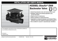
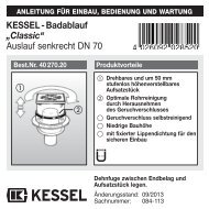
INSTRUCTIONS FOR ASSEMBLY, OPERATION AND MAINTENANCE<strong>KESSEL</strong> - <strong>backwater</strong> <strong>pumping</strong> <strong>station</strong>Pumpfix ® F <strong>Standard</strong>/<strong>Comfort</strong>for wastewater with and without sewageProduct advantagesFor wastewater with and without sewageBackwater flap and draining pumpSimple installation in through pipesPlug & play control unitControl unit with self-diagnosis system(SDS) with integrated battery back-upFig. shows:Pumpfix ® F <strong>Comfort</strong>for installation in theground plateStraightforward replacement of wearingpartsSimple tool-free servicingAdditional advantages of the Komfortversion:Control unit with displayMotor-driven locking of the <strong>backwater</strong>flapIntegrated drain function for surfacewater drainageFig. shows:Pumpfix ® F <strong>Standard</strong>for installation in anexposed pipeLGALandesgewerbeamt BayernBauartgeprüftund überwachtmit Sicherheitgeprüfte QualitätThe installation and service of this unit should be carriedout by a licensed professional servicerName/Sign Date TownStampSubject to technical amendmentsStand 04/2011ID-Number 010-843EN
Table of contents1. Safety instructions ........................................................................................................... Page 22. General points 2.1 Use ..................................................................................................... Page 32.2 Scope of supply.................................................................................. Page 32.3 Installation procedure ......................................................................... Page 32.4 General instructions about the installation of <strong>backwater</strong> valves ......... Page 33. Installation 3.1 Installation in the ground plate............................................................ Page 43.2 Recessed installation in the ground plate........................................... Page 43.3 Ventilation connection ........................................................................ Page 43.4 Installation in an exposed wastewater pipe ........................................ Page 53.5 Installation in water load..................................................................... Page 53.6 Special features of Pumpfix ® F <strong>Comfort</strong> ............................................. Page 53.7 Set-up................................................................................................. Page 54. Service and maintenance 4.1 Service ..................................................................................................... Page 64.2 Maintenance............................................................................................. Page 64.2.1 Mounting the two covers........................................................................... Page 64.3 Test ......................................................................................................... Page 64.3.1 Test <strong>Standard</strong> ........................................................................................... Page 64.3.2 Test <strong>Comfort</strong> ............................................................................................. Page 64.4 Pump removal .......................................................................................... Page 74.5 Motor installation ...................................................................................... Page 74.6 Removing motor ground installation......................................................... Page 74.7 How the emergency valve works.............................................................. Page 84.7.1 <strong>Standard</strong>................................................................................................... Page 84.7.2 <strong>Comfort</strong>..................................................................................................... Page 84.8 Servicing the ventilation ........................................................................... Page 85. Spare parts 5.1 <strong>Standard</strong>............................................................................................. Page 95.2 <strong>Comfort</strong>............................................................................................... Page 106. Warranty ......................................................................................... ................. Page 117. Commissioning protocol for the installer ........................................................................................................... Page 128. Commissioning protocol for the installation company...................................................................................... Page 14Dear customer,Before you put your <strong>backwater</strong> <strong>pumping</strong><strong>station</strong> Pumpfix ® F into operation,please read through the installation instructionscarefully and follow them.1. Safety instructionsCheck first whether the system has arrivedundamaged. In the event of transportdamage, please follow the instructions inchapter 6 “Warranty”.1. Safety instructions:During installation, operation, maintenanceor repair of the system, the regulationsfor the prevention of accidents, the pertinentDIN and VDE standards and directives,as well as the directives of the localpower supply industry must be heeded.Before putting the device into operation,make sure through professional examinationthat the necessary protective featuresare available. Grounding, neutral, residualcurrent-operated protective circuit etc.must correspond to the requirements ofthe local power supply industry.The system must not be operated in potentiallyexplosive areas.The system contains electric charges andcontrols rotating mechanical system components.Non-compliance with the operatinginstructions may result in considerabledamage to property, personal injuriesor even fatal accidents.The system must be disconnectedfrom the mains or made currentlessbefore any work is carriedout on it.It must be ensured that the electric cablesas well as all other electrical systemequipment are in a faultless condition. Incase of damage, the system may on noaccount be put into operation or must bestopped immediately.The system must be inspected and servicedaccording to DIN 1986 to maintain itsoperational ability.We recommend that you conclude a servicingcontract with your installation company.No repairs or maintenance work may becarried out during a <strong>backwater</strong> situation orif a <strong>backwater</strong> situation is imminent. The<strong>backwater</strong> flaps and the locking lever alwayshave to be able to be moved freely.Note:No system components may be installedin protection zone 0 or 1 in accordancewith DIN VDE 0100 701. In the case offlush-to-floor showers, zone 1 is definedas with a radius of 1.20 m (projected areaon the floor) around the water intake point.Deviating local regulations must be takeninto account.The regulations set out by the directivesVDE 0100, VDE 01107, IEC or by the localpower supply industry must be heeded.The control unit must not be installed inrooms where there is an explosion hazard.For the operation of this system,these instructions and instructions no.010-846 must be used together!2
2. General2.1 UseThe <strong>KESSEL</strong> <strong>backwater</strong> <strong>pumping</strong> <strong>station</strong>Pumpfix ® F has been designed for throughwastewater pipes that have soiled waterpipes as well as toilets and urinals connectedto them. This guarantees the safe drainingof draining spots below the <strong>backwater</strong>level even during <strong>backwater</strong>. The pump onlyworks during <strong>backwater</strong> and pumps the soiledwater into the sewage channel againstthe <strong>backwater</strong>. During <strong>backwater</strong>-free operation,the soiled water is discharged intothe sewage channel through the naturalgradient.Pumpfix ® does not provide protectionagainst rats! If there is a rat hazard, the systemmust be protected from damage onsite.A rat protection flap is available as an optionand prevents damage caused by gnawingto a large extent (<strong>Standard</strong> only).Important:Pre-condition for trouble-free operation is• Sufficient gradient in the draining pipes(note: there is a gradient of 9 mm betweenfeed and drain with Pumpfix® F)• A high share oSufficient gradient in thedraining pipes (note: there is a gradientof 9 mm between feed and drain withPumpfix® F)• A high share of water in the wastewaterto optimise the self-cleaning effect• Correct routing and ventilation of thefeed pipe in accordance with DIN EN12056 / DIN 1986-100• Use with greasy wastewater only possiblewith increased maintenance andcleaning efforts• Rain surfaces up to max. 20 m 22.2 Scope of supplyThe scope of supply of the <strong>KESSEL</strong> <strong>backwater</strong><strong>pumping</strong> <strong>station</strong> Pumpfix ® F ismade up of the drain body with pump and<strong>backwater</strong> valve and the electric packages.The electric packages are made up of:<strong>Standard</strong>1. The optical probe2. A control unit (mains connection 230 V,50 Hz, protective rating IP 54) with batteryback-up (2 x 9V) for alarm messagein the event of a power failure.3. An installation and operating manual<strong>Comfort</strong>1. Two optical probes and the drive motor2. One control unit with display (mainsconnection 230 V, 50 Hz, protective ratingIP54) with battery back-up (2 x 9V) foralarm message in the event of a powersupply.3. An installation and operating manual2.3 Installation procedureDuring the construction phase only the drainbody is installed and connected in accordancewith chapter 3. Usually, the powerconnection (chapter 4) and subsequent initialoperation (chapter 5) cannot be carriedout directly. Please connect the electric systemcomponents (pump, probes, motorand control unit, depending on the variant)when you put the <strong>KESSEL</strong> <strong>backwater</strong> <strong>pumping</strong><strong>station</strong> Pumpfix® F into operation. Untilthis point, the enclosed electric packageand the control unit must be kept stored in aclean and dry place. Only remove the plugend plates when the system is put into operation.Care must be taken that the system is alwayssealed with an upper cover sectionand cover or protective hood when set up asa free-standing device in order to preventsoiling of the system.Caution: The pump is secured by a transportationsafety tape that has to be removedbefore initial operation.2.4 General instructions about the installationof <strong>backwater</strong> valvesAccording to DIN EN 12056 <strong>backwater</strong> valvesmay not be used to protect all the drainingpoints of a building - including thoseabove the <strong>backwater</strong> level (street level) - becauseif the <strong>backwater</strong> valve is closed, thewastewater from above can no longer bedrained into the sewage pipe but will - accordingto the principle of communicatingpipes - escape from the drainage points furthestbelow the <strong>backwater</strong> level first (usuallybasement rooms) and thus flood the basement.Only draining points below the <strong>backwater</strong>level may be protected against <strong>backwater</strong>.All draining points above the <strong>backwater</strong>level must be discharged into the sewagepipe with free gradient past the <strong>backwater</strong>valve.Consequence: separate pipe routing.Domestic wastewater above the <strong>backwater</strong>level can thus rise up to a maximum of streetlevel inside the downpipe without floodingthe basement.Rainwater must never be discharged via<strong>backwater</strong> valves.Installation of a <strong>backwater</strong> valve in the right placeInstallation of a <strong>backwater</strong> valve in the wrong placeRight!Wrong!BackwaterlevelBackwaterlevelBackwater protectionBackwater protection3
3. InstallationPlease note:DIN EN 12056 must always be heeded whenrouting the base pipes. Downpipes must alwaysbe introduced downstream from thePumpfix® F (about 1m). In addition, a stillingsection must be observed upstream and downstreamof the FKA (at least 1 m). During installationof the <strong>backwater</strong> valve, care must betaken that there is a sufficient gap to the wallfor maintenance work to be carried out. TheKG pipe must not be connected directly to thedrain body but only to the muff.Caution: During installation pay attentionto the direction of flow arrows on the product.3.1 Kessel <strong>backwater</strong> <strong>pumping</strong> <strong>station</strong>Pumpfix ® F for installation in theground plateDThe drain body of the <strong>KESSEL</strong>-Pumpfix® Fmust be aligned horizontally (see Fig. 1).For connection of the electric cables of probeand pump, a cable conduit (at least DN 50,Kessel recommends 2 x 45° bends) must beprovided. A second probe cable and motorconnection cable must be connected for theKomfort variant. For this, a cable conduit (atleast DN 70, Kessel recommends 2 x 45°bends) must be planned. To do this, lay thecable conduit to at least finished flooring height(see Fig. 2) and insert in the cable duct in theadapter of the <strong>KESSEL</strong> Pumpfix® F (cableconduit should protrude about 2 cm into the interior- tightness (Fig. 5). Changes of directionmust be laid with bends of max. 45°. To guaranteeproper aerating and venting of the pumpchamber, the cable conduit must not be sealedairtight. Insert the enclosed profile lip seal intothe adapter groove and grease this. Thenmount the upper cover section (see Fig. 3).Thanks to the telescopic design of the uppercover section, the <strong>KESSEL</strong>-Pumpfix® F can beadapted exactly to the prevailing installationdepth. Ground slopes of up to 5° can be compensated.The upper cover section can also beturned to align the cover to the tile pattern, forexample (see Fig. 4). The seal must bechecked for a good fit after adjustment.CAUTION:The upper cover section must be shortenedto the necessary size to achieve minimuminstallation depth. If necessary,recesses must be cut out of the uppercover section near the cable conduit andthe ventilation pipe. Maximum groundwaterresistance is 2 m. Following finalalignment of the upper cover section, arecess may have to be introduced nearthe cable duct to enable the cable to bepulled out again during later inspections(see Fig. 5).The lip seal must be fitted in the cover plate.Care must be taken that the sealing lip andcentring lug are facing upwards during installation.The centring lug must be placed in therecess (see Fig. 6).During installation, make sure that the functionof units in the chamber is not impaired by constructionmaterial.Installation of covers with a choice of finishes(tile height max. 15 mm).With the covers with a choice of finishes, tilesor natural stone can be inserted in the cover onsite, so that they can be matched to the roomʼsflooring. Products e.g. from PCI, Schomburg,Deitermann are suitable for tile laying. Toachieve straightforward processing and adhesion,we recommend the following procedure:Tile laying:a) aPrime the cover plate e.g. with PCI primer303. Following the respective flash-off time,lay the tiles with silicone. This type of layingis particularly suitable for thinner tiles sincethe base can be filled up to the requiredheight.b) Laying the tiles e.g. using PCI Silcoferm S(self-adhesive silicone). This allows a thinadhesive bed to be used, particularly goodfor thicker tiles.Laying natural stone:(marble, granite, agglo-marble):a) Prime the cover plate e.g. with PCI primer303. Lay the natural stone panels using e.g.PCI-Carralit..b) Laying the natural stone panels using e.g.PCI-Carraferm (special silicone for naturalstone). Areas of application analogue to“Laying tiles”.3.2 Recessed installation in the groundplate(order no. 83071). Chapter 3.4 must be heededfor installation in water load.Depending on the installation depth, one ormax. two extension pieces can be used betweenthe upper cover section and the adapter.The respective seals must be greased accordingly.Please note that with recessed installation youstill have to be able to reach down to the drainbody for maintenance purposes.3.3. Ventilation connectionPumpfix® F is fitted as standard with a ventilationvalve with activated carbon filter. Alternatively,ventilation accordingto standardcan be connected. Forthis, the ventilationvalve can be removedand connected directlyto a ventilation pipe(to the roof).Fig. 1fig. 2Fig. 3Fig. 4fig. 5Fig. 64
3. Einbau3.4 Installation in an exposed wastewaterpipeThe version for free-standing set-up is deliveredwith a protective hood to prevent damage tothe components following commissioning. Fig.7 shows the cable ducts – 1 or 2 (depending onthe variant).3.5 Installation in water load(Seal set art. no. 83023Fig. 7If the valve is to be installed in water load,the flange serves as the necessary sealinglevel for a white or black tub (see Figure).For this purpose, seal sheeting is clampedbetween the plastic counterflange and thecompression seal flange integrated on thedrain body, and screwed together using theenclosed screws.The sheeting used on site can be used asseal sheeting. For installation in a waterproofwhite tub, <strong>KESSEL</strong> also has matchingseal sheeting available made of natural rubberNK/SBR, where the bore holes for thescrews have already been cut out (see Fig.8).If it is necessary to perforate the waterproofconcrete tub to connect feed pipes, cableconduits etc., these holes must also be setup waterproof. Maximum groundwater resistanceis 2 m.Installation with extension (order no.83071).Use of the extension allows the flangeheight to be individually adjusted. Theattachment must be shortened to the requiredheight if necessary.3.6 Special features of Pumpfix ® F<strong>Comfort</strong>Pumpfix F Komfort has an integrated drainingfunction for surface water drainage.3.7 Set-upConnection of the draining function to thefeed cover is via the enclosed drainingconnection. Insert the draining connectioninto the prescribed opening and lock usingthe one-handed quick-action closure.Depending on installation depth (installationdepth of the upper cover section), thedraining connection must be shortened tothe respective length (see Fig. 9) or extendedusing HT-pipe DN 70 if recessed installationusing extension (art. no. 83071) isused.Fig 9Seal seat (83023)• Counterflange • Sealing sheetFig. 8PressdichtungsflanschPumpfix ® F <strong>Comfort</strong>SInstallation example “black tub”Installation example “white tub”BWS*Tiles FliesenScreed EstrichInsulation DämmungConcrete Betonboden floorProtective Schutzbeton concreteSealing AbdichtungUnderfloor UnterbetonBWS *Tiles FliesenScreed EstrichInsulation DämmungConcrete Betonboden floor➇➅➆42314521WU-Beton➀ <strong>KESSEL</strong>-Pumpfix® F, Staufix® FKA, Staufix® SWA, Controlfix➁ Compression seal flange with seal set art. no. 83023➂ Extension art. no. 83071➃ Adapter DN 100 with compression seal flange made of stainlesssteel art. no. 27198➄ Elastomer sealing sheet art. no. 27159➅ Upper cover section with plastic cover plate➆ Control unit➇ Locking lever5
4. Service and maintenance4.1 ServiceThe system must be checked once everymonth by the operator through observationof the switching routine for operationalability and leaks.• Close emergency valve or with Komfort:press test key to carry out functional teston <strong>backwater</strong> valve -> valve closes• Allow water to flow in• Wait until level-LED + pump trigger.• Switch off water feed• Switch off level-LED and wait for pump• Open hand lever (vertical position OPEN)-> <strong>Standard</strong>Komfort: Please note that the <strong>backwater</strong>valve must be open after the inspectionhas been completed.The pump should be checked at regular intervals.If operational noises increase,<strong>pumping</strong> capacity decreases or there arevibrations in the pipeline system, the pumphousing and impeller must be checked forany stubborn soiling or wear.4.2 Maintenance (at least every sixmonths)CAUTION: Disconnect the unit from themains during all servicing work! Heedsafety instructions! No warranty will begranted in the event of insufficientmaintenance! All the servicing andmaintenance work described belowmay only be carried out by authorisedqualified personnel. Repairs may onlybe carried out by the manufacturer.DIN 1986, part 3, must be heeded duringmaintenance work on systems. Maintenancework must be carried out at least everysix months by authorised qualified staff.The following tasks have to be carried out:• Visual inspection of the complete system• Thorough cleaning of the complete systemand the pump• Check on the complete system and pumphousing for external damage and visiblewear• Check on the pump for free movement,wear and deposits• Check the connection cables for mechanicaldamage and wear• Check the seal connections for leaks andany recognisable wear• Insulation test on the pump motor• Check the control unit for damage andsoiling• Check and clean the ventilation valve• Clean the optical probe<strong>Standard</strong>a) Pull the insertable part outb) Clean all the partsc) Check the sealsd) Apply lubricant (e.g. fittings grease)to the outside of the seals of the insertableparts as well as the guideparts of the flap valvesWe recommend these jobs after longer periodsof standstill or intermediate storage, too,as well as after longer or frequent occurrencesof <strong>backwater</strong>. If problems should occurthat cannot be eliminated, please contactthe specialist company who carried out theinstallation (see stamp on cover sheet) if indoubt.4.2.1 Mounting the two covers (see Fig.12, 13, 14)Insert the covers on one side, push the otherside down and lock in place using the lockinglevers. During installation of the overflowcover the red flap lever or the motor flap positionmust always be “CLOSED”4.3 Teste) Insert the insertable part exactlyf) Make sure the attachment clips are inplace properly!g) Heed cover installation 4.2.1h) Carry out functional test in accordancewith instruction manual 010-846.Abb. 12<strong>Comfort</strong>4.3.1 Test <strong>Standard</strong>1. Hold the pump probe into the water "On" level Level-LED litPump startsPump-LED lit4.3.2 Test <strong>Comfort</strong>1. Hold the motor probe into the water Flap closes Backwater-LED flashesFlap-LED flashesFlap closedBackwater-LED flashesFlap-LED lit2. Hold the pump probe into the water Pump starts Pump-LED lit6
4. Service and maintenance4.4 Pump removal:The pump can be removed individually.To do this, turn both pump removal leversthrough 180°. This makes them fold outwardsto the side so that the pump can belifted out.Fig. 13 shows the <strong>Comfort</strong> variantLock both sides!Locking levermuffLocking levermuffPump removalleverPump removallever4.5 Motor installation:The levelled drive shaft of the motor mustbe in a vertical position (state on delivery).Move the locking lever of the operatingvalve on the locking cover to the“CLOSED” position, insert the drivemotor into the drive groove from above,and screw in place using the four M5 x 12screws (TX25) on the locking cover (Fig.16).Fig. 144.6 Removing motor ground installation❶❹❷❸❺Fig. 15Probe testFig. 16Motor installationIn this case, the outlet cover must be dismantledto remove the motor. To do this,open the locking lever and take the outletmuff out. Loosen levers 2 and 3 andremove the bypass muff, to do this tiltpump connection muff 4 away or removethe pump if necessary. After removingthe two cover locking levers 5 the outletcover can be removed. Now the motorcan be screwed off.7
4. Service and maintenance4.7 How the emergency valve works4.7.1 <strong>Standard</strong>Locking position (Fig. 17, emergencyvalve completely closed): The hand leverof the emergency valve must be put in therespective CLOSED position. The <strong>backwater</strong>flap works as a pipe barrier. Thisfunction is only considered as protectionfrom <strong>backwater</strong> during longer periods ofabsence (e.g. holidays).Fig. 17 BleederConnected draining points are still drained.The emergency valve must be releasedagain for normal operation.Abb. 17Fig. 18 Activated carbon filterFig. 19 CoverEmergency flap can be locked by hand4.7.2 KomfortLocking position: The <strong>backwater</strong> flap isclosed by pressing the TEST key (flap).The <strong>backwater</strong> flap works as a pipe barrier.This function is only considered asprotection from <strong>backwater</strong> during longerperiods of absence (e.g. holidays).Connected draining points are still drained.After return, the emergency valvemust be released again for normaloperation: by pressing the TEST key(flap) again.Make sure that there is no <strong>backwater</strong>when this takes place.The bleeder (Fig. 17 from right to left) comprisesseal, drain body, float ball, seal,bayonet locking cap, activated carbon filterand cover.Pull the cover off (Fig. 19) by tilting it slightlyto the side. Then turn bayonet lockingcap (Fig. 20) ➀ and pull it up and off 2.Remove seal and float ball and clean everything.Re-assembly takes place in reverseorder.➀ ➁4.8 Servicing the ventilationThe ventilation (see spare parts section 6)must be cleaned regularly and the activatedcarbon filter (Fig. 18) must be changedannually or as required.The ventilation must be cleaned andchecked after every pump failure.Fig. 20 Bayonet locking cap8
5. Spare parts5.1 <strong>Standard</strong>Pumpfix ® F for installation in an exposed wastewater pipeAll spare parts can be purchased from a specialist company.DesignationArt. no.➀ Pumpfix ® F-control unit <strong>Standard</strong> IP 54 28073a) Additional board for potential-free contact 80072b) Remove signal generator 20 m 20162c) Battery 9V (2 units required) 197-081➁ Optical probe IP 68 (5 m, inc. adapters) 80888➂ Cover pump feed side (without outlet function) 28052➃ Pumpfix ® F-cover <strong>Standard</strong> outlet side 28053➄ Pumpfix ® F-pump IP 68 (5m, inc. plug) 28351➅ Ventilation complete 28060a) Activated carbon filter 28061➆ Mechanical flap 80033➇ Insertion part for mechanical flap 80034➈ Hood 80031 Transition piece 83032 a➆➀a,b,cSeal set II 70319Pumpfix ® F for installation in the ground plateAll spare parts can be purchased from a specialist company.DesignationArt. no.➀ Pumpfix ® F-control unit <strong>Standard</strong> IP 54 28073a) Additional board for potential-free contact 80072b) Remove signal generator 20 m 20162c) Battery 9V (2 units required) 197-081➁ Optical probe IP 68 (5 m, inc. adapters) 80888➂ Cover pump feed side (without outlet function) 28052➃ Pumpfix ® F-cover <strong>Standard</strong> outlet side 28053➄ Pumpfix ® F-pump IP 68 (5m, inc. plug) 28351➅ Ventilation complete 280606a) Activated carbon filter 28061➆ Mechanical flap 80033➇ Insertion part for mechanical flap 80034Seal set II 70319➂➄➁ a➀a,b,c9
6. Warranty1. In the case that a <strong>KESSEL</strong> product is defective,<strong>KESSEL</strong> has the option of repairingor replacing the product. If the productremains defective after the secondattempt to repair or replace the product orit is economically unfeasible to repair orreplace the product, the customer hasthe right to cancel the order / contract orreduce payment accordingly. <strong>KESSEL</strong>must be notified immediately in writing ofdefects in a product. In the case that thedefect is not visible or difficult to detect,<strong>KESSEL</strong> must be notified immediately inwriting of the defect as soon as it is discovered.If the product is repaired or replaced,the newly repaired or replacedproduct shall receive a new warrantyidentical to that which the original (defective)product was granted. The term defectiveproduct refers only to the productor part needing repair or replacementand not necessarily to the entire productor unit. <strong>KESSEL</strong> products are warrantedfor a period of 24 month. This warrantyperiod begins on the day the product isshipped form <strong>KESSEL</strong> to its customer.The warranty only applies to newly manufacturedproducts. Additional informationcan be found in section 377 of theHGB.In addition to the standard warranty,<strong>KESSEL</strong> offers an additional 20 year warrantyon the polymer bodies of class I / IIfuel separators, grease separators, inspectionchambers, wastewater treatmentsystems and rainwater storagetanks. This additional warranty applies tothe watertightness, usability and structuralsoundness of the product.A requirement of this additional warrantyis that the product is properly installedand operated in accordance with the validinstallation and user's manual as well asthe corresponding norms / regulations.2. Wear and tear on a product will not beconsidered a defect. Problems with productsresulting from improper installation,handling or maintenance will also be considereda defect.Note: Only the manufacturer may opensealed components or screw connections.Otherwise, the warranty may becomenull and void01.06.201011
7. Commissioning Protocol for installerSeparator Type:__________________________________________________________Day / Hour__________________________________________________________Project description /Building services supervisor __________________________________________________________AddressTelephone / Fax____________________________________________________________________________________________________________________BuilderAddressTelephone / Fax______________________________________________________________________________________________________________________________________________________________________________PlannerAddressTelephone / Fax______________________________________________________________________________________________________________________________________________________________________________Contracted plumbing companyAddressTelephone / Fax______________________________________________________________________________________________________________________________________________________________________________<strong>KESSEL</strong>-Commissions no.:System operator /ownerAddressTelephone / Fax______________________________________________________________________________________________________________________________________________________________________________UserAddressTelephone / Fax______________________________________________________________________________________________________________________________________________________________________________Person of delivery__________________________________________________________Other remarks__________________________________________________________The system operator, and those responsible, were present during the commissioning of this system.____________________________ ____________________________ ____________________________Place and date Signature owner Signature user12
Notice13
8. Commissioning Protocol for installation companyHandover certificate (copy for the company carrying out the installation)❏❏❏The initial operation and instruction was carried out in the presence of the person authorised to perform the acceptanceand the system operator.The system operator/person authorised to perform the acceptance was informed about the obligation to servicethe product according to the enclosed operating instructions.Initial operation and instruction were not carried out.The client/ person responsible for initial operation was handed the following components and/or product componentsInitial operation and instruction is being carried out by (company, address, contact, phone)The exact coordination of the dates for initial operation/instruction is being carried out by the system operator and personresponsible for initial operation.Place, date Signature of person Signature of system operator Signature of the companyauthorised to perform acceptancecarrying out the installation work14
❑ Backwater protection❑ Lifting Stations and pumps❑ Drains and shower channels❑ Separators-Grease Separators-Oil-/Fuel-/CoalescenceSeparators-Starch Separators-SedimentSeparators❑ Septic Systems❑ Inspection Chambers❑ Rainwater ManagementSystems