MULTI-PLATE PRODUCT GUIDE - Armtec
MULTI-PLATE PRODUCT GUIDE - Armtec
MULTI-PLATE PRODUCT GUIDE - Armtec

Create successful ePaper yourself
Turn your PDF publications into a flip-book with our unique Google optimized e-Paper software.
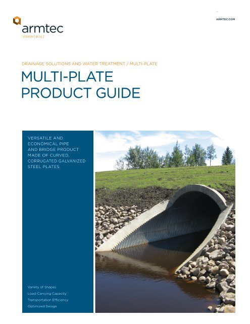
<strong>MULTI</strong>-<strong>PLATE</strong>SHAPESBy varying the combination of plate length, width, and radius, a wide range ofstructures may be designed and constructed. Spans range from 1.5m up to 18mconfigurations. All structures can be built using basic construction tools andwithout specialized labour._AVAILABLE SHAPES• Round Pipe• Pipe Arch• Ellipses (Vertical or Horizontal)• Arch• UnderpassROUND PIPETechnical DataStandardInsideDiameterPeripheryHole Spaces End Areamm N m 21,500 20 1.771,660 22 2.161,810 24 2.581,970 26 3.042,120 28 3.542,280 30 4.072,430 32 4.652,590 34 5.262,740 36 5.913,050 40 7.323,360 44 8.893,670 48 10.613,990 52 12.474,300 56 14.494,610 60 16.664,920 64 18.995,230 68 21.465,540 72 24.085,850 76 26.866,160 80 29.796,470 84 32.876,780 88 36.107,090 92 39.487,400 96 43.017,710 100 46.708,020 104 50.53Number of Plates/Ring(For Standard Layout)5N 6N 9N Total4 0 0 42 2 0 40 4 0 44 1 0 52 3 0 50 2 2 41 0 3 42 1 2 50 0 4 42 2 2 61 2 3 60 2 4 62 1 4 71 1 5 70 1 6 72 0 6 81 0 7 80 0 8 82 2 6 101 2 7 100 2 8 102 1 8 111 1 9 110 1 10 112 0 10 121 0 11 12Nominal Weight of Structure(kg/m) Bolts IncludedSpecified Steel Thickness (mm)3.0 4.0 5.0 6.0 7.0180 234 288 342 396195 254 313 373 432211 275 339 403 467232 302 373 443 513248 323 398 473 548257 335 415 494 572272 356 440 524 608294 384 474 564 654303 396 490 584 678346 452 559 665 771377 493 609 725 841408 534 660 786 911445 582 719 856 993476 623 770 916 1,063507 663 820 977 1,134544 711 880 1,047 1,215575 752 930 1,108 1,285- 793 981 1,168 1,356- 849 1,049 1,249 1,449- - 1,100 1,309 1,519- - 1,150 1,370 1,589- - 1,210 1,440 1,671- - - 1,501 1,741- - - 1,561 1,812- - - - 1,893- - - - 1,963NOTE:• N = 9.6” (243.84mm)• Weights based on 3,660mm plate lengths• All weights include bolts and nuts• All dimensions are to inside of the crest of the corrugation and all figures shownare subject to manufacturing tolerances as per CSA G 401• 5N, 6N and 9N designate number of circumfirential hole spaces in plate
<strong>MULTI</strong>-<strong>PLATE</strong>PIPE ARCHESTechnical DataNominal DimensionsSpanRisePeripheryHole SpacesEndAreamm mm N m 22,060 1,520 24 2.492,240 1,630 26 2.902,440 1,750 28 3.362,590 1,880 30 3.872,690 2,080 32 4.493,100 1,980 34 4.833,400 2,010 36 5.283,730 2,290 40 6.613,890 2,690 44 8.294,370 2,870 48 9.764,720 3,070 52 11.385,050 3,330 56 13.245,490 3,530 60 15.105,890 3,710 64 17.076,250 3,910 68 19.18Number of Plates/Ring(For Standard Layouts)5N 6N 9NTCB TCB TCB Total021 000 100 4121 100 000 5020 201 000 5120 001 100 5220 1 0 1 000 6020 100 1 0 1 5021 1 0 1 100 6020 002 200 61 2 1 001 200 7021 100 201 7020 001 301 7022 201 200 9120 000 302 8221 1 0 1 201 10220 002 301 10Nominal Weight of Structure(kg/m) Bolts IncludedSpecified Steel Thickness (mm)3.0 4.0 5.0 6.0 7.0210 274 339 403 467232 302 373 443 513248 323 398 473 548263 343 423 503 583285 371 458 544 630294 384 474 564 654316 412 508 604 700346 452 559 665 771384 501 618 735 852414 541 669 795 922445 582 719 856 993- 638 787 936 1,085- - 829 987 1,145- - 897 1,067 1,237- - 948 1,128 1,308NOTE:• N = 9.6” (243.84mm)• Weights based on 3,660mm plate lengths• All weights include bolts and nuts• All dimensions are to inside of the crest of the corrugation and all figuresshown are subject to manufacturing tolerances as per CSA G 401• 5N, 6N and 9N designate number of hole spaces in plate• T = Top, C = Corner, B = Bottom
<strong>MULTI</strong>-<strong>PLATE</strong>ELLIPSESHorizontal EllipseTechnical DataSeriesNumberInsideSpanRiseInsideTotalInside PlateEndAreaRadiiR sR tmm mm N m 2 mm mm27E15 2,470 1,750 28 3.34 675 1,54530E15 2,690 1,840 30 3.81 675 1,72033E15 2,920 1,920 32 4.37 675 1,89530E18 2,790 2,050 32 4.48 815 1,72036E15 3,140 2,000 34 4.83 675 2,07033E18 3,020 2,130 34 5.02 815 1,89536E18 3,240 2,210 36 5.57 815 2,07042E15 3,590 2,160 38 5.96 675 2,42045E15 3,820 2,240 40 6.55 675 2,59542E18 3,690 2,380 40 6.78 815 2,42045E18 3,920 2,460 42 7.43 815 2,59548E18 4,140 2,540 44 8.08 815 2,77051E18 4,370 2,620 46 8.78 815 2,94542E27 3,990 3,020 46 9.48 1,230 2,42054E18 4,590 2,700 48 9.50 815 3,12045E27 4,220 3,100 48 10.22 1,230 2,59548E27 4,440 3,180 50 11.06 1,230 2,77051E27 4,660 3,260 52 11.89 1,230 2,94554E27 4,890 3,350 54 12.72 1,230 3,12057227 5,110 3,430 56 13.61 1,230 3,29551E33 4,860 3,690 56 14.03 1,510 2,94560E27 5,340 3,510 58 14.49 1,230 3,46554E33 5,090 3,770 58 15.02 1,510 3,12063E27 5,560 3,590 60 15.42 1,230 3,46057E33 5,310 3,860 60 16.00 1,510 3,29566E27 5,790 3,670 62 16.44 1,230 3,81560E33 5,540 3,940 62 17.00 1,510 3,46569E27 6,010 3,750 64 17.39 1,230 3,99063E33 5,760 4,020 64 18.04 1,510 3,64072E27 6,240 3,840 66 18.40 1,230 4,16566E33 5,990 4,100 66 19.09 1,510 3,81575E27 6,460 3,920 68 19.44 1,230 4,34069E33 6,210 4,180 68 20.17 1,510 3,990Number of Plates/Ring5N 6N 9NTB S TB S TB S Total0 2 0 0 2 0 44 2 0 0 0 0 62 2 2 0 0 0 64 0 0 2 0 0 60 2 4 0 0 0 62 0 2 2 0 0 60 0 4 2 0 0 62 2 0 0 2 0 60 2 2 0 2 0 62 0 0 2 2 0 60 0 2 2 2 0 64 0 2 2 0 0 82 0 4 2 0 0 82 0 0 0 2 2 60 0 6 2 0 0 80 0 2 0 2 2 64 0 2 0 0 2 82 0 4 0 0 2 80 0 6 0 0 2 84 0 0 0 2 2 82 2 4 2 0 0 102 0 2 0 2 2 80 2 6 2 0 0 100 0 4 0 2 2 84 2 0 2 2 0 104 0 4 0 0 2 102 2 2 2 2 0 102 0 0 0 4 2 80 2 4 2 2 0 100 0 2 0 4 2 84 2 4 2 0 0 124 0 2 0 2 2 102 2 0 2 4 0 10Nominal Weight of Structure(kg/m) Bolts IncludedSpecified Steel Thickness (mm)3.0 4.0 5.0 6.0 7.0242 316 391 464 539270 352 434 514 597285 372 459 545 633285 372 459 545 633301 393 485 576 668301 393 485 576 668317 413 510 607 703331 431 532 633 734347 454 561 667 773347 454 561 667 773363 474 586 698 809391 510 629 747 867405 529 652 777 900394 514 637 757 879407 533 659 787 913409 535 662 789 914437 571 705 838 972450 590 729 867 1,006452 593 735 877 1,018- 629 777 926 1,074495 647 798 945 1,098- 651 805 958 1,111- 651 805 958 1,111- 671 831 989 1,146- 686 845 1,006 1,165- - 873 1,038 1,204- 707 873 1,038 1,204- - 878 1,047 1,216- - 897 1,069 1,240- - 904 1,079 1,253- - 940 1,118 1,295- - 947 1,128 1,308- - 947 1,128 1,308NOTE:• N = 9.6” (243.84mm)• Weights based on 3,660mm plate lengths• All weights include bolts and nuts• All dimensions are to inside of the crest of the corrugation and all figuresshown are subject to manufacturing tolerances as per CSA G 401. 5N, 6Nand 9N designate number of hole spaces in plate• T = Top, B = Bottom, S = Side• Rs = Radius Side, Rt = Radius Top• Contact your nearest <strong>Armtec</strong> Sales Office for Vertical Ellipse Shapes
<strong>MULTI</strong>-<strong>PLATE</strong>cof BoltARCHESTechnical DataRSpanNominal DimensionsPeripherySpan Rise Holes SpacesWaterWayAreaRiseRadiusmm mm N m 2 mm1,520 810 10 0.98 7601,830 840 11 1.16 930970 12 1.39 9102,130 860 12 1.39 1,0901,120 14 1.86 1,0702,440 1,020 14 1.86 1,2301,270 16 2.42 1,2202,740 1,180 16 2.46 1,4001,440 18 3.07 1,3703,050 1,350 18 3.16 1,5401,600 20 3.81 1,5203,350 1,360 19 3.44 1,7101,750 22 4.65 1,6803,660 1,520 21 4.18 1,8501,910 24 5.48 1,8303,960 1,680 23 5.02 2,0102,060 26 6.50 1,9804,270 1,840 25 5.95 2,1602,210 28 7.43 2,1304,570 1,870 26 6.41 2,3402,360 30 8.55 2,2904,880 2,030 28 7.43 2,4802,520 32 9.75 2,4405,180 2,180 30 8.55 2,6202,690 34 11.06 2,5905,490 2,210 31 9.01 2,8202,720 35 11.71 2,7405,790 2,360 33 10.22 2,5.902,880 37 13.01 2,9006,100 2,530 35 11.52 3,1003,050 39 14.59 3,050116308638 38c4.24076No. of Plates/Ring(For Standard Layouts)Footing Channel5N 6N 9N Total2 0 0 21 1 0 20 2 0 20 2 0 21 0 1 21 0 1 22 1 0 32 1 0 30 0 2 20 0 2 21 1 1 32 0 1 32 2 0 40 2 1 30 1 2 31 3 0 41 2 1 42 1 1 42 0 2 41 2 1 40 2 2 42 0 2 41 0 3 40 2 2 42 1 2 52 2 1 51 2 2 50 1 3 42 0 3 51 2 2 50 2 3 5NOTE:• N = 9.6” (243.84mm)• Weighs based on 3,660mm plate lengths• All weights include bolts and nuts• All dimensions are to inside of the crest of the corrugation and all figures shown are subject tomanufacturing tolerances as per CSA G 401• 5N, 6N and 9N designate number of hole spaces in plateRSpanFOOTING CHANNELof BoltRise1163086c of Bolt38 3876c of Bolt4.240Nominal Weight of StructureFooting (kg/m) Channel Bolts includedSpecified Steel Thickness (mm)3.0 4.0 5.0 6.0 7.087 114 141 168 19595 124 154 183 213102 134 166 198 230102 134 166 198 230118 155 192 229 266118 155 192 229 266139 183 226 269 312139 183 226 269 312148 195 242 289 336148 195 242 289 336170 223 276 329 382163 213 264 314 365192 251 310 370 429178 233 289 344 400201 264 327 390 453203 264 326 388 449223 292 361 430 499215 282 348 415 481238 312 386 460 534223 292 361 430 499254 332 412 491 569238 312 386 460 534- 353 437 521 605- 332 412 491 569- 381 471 561 654- 350 433 516 598- 391 484 576 669- - 450 536 622- - 509 606 704- - 484 576 669- - 534 637 739
<strong>MULTI</strong>-<strong>PLATE</strong>UNDERPASS_NOTE:For additional information onunderpasses, contact your nearest<strong>Armtec</strong> sales officeTechnical DataNominal DimensionsInside Plate RadiiSpanRisePeriphery EndHole Spaces AreaBDimR tR sR cR b 5N 6N 9NTotalPlatesmm mm N m 2 mm mm mm mm mm TSCB TSCB TSCB3,750 3,340 47 10.0 1,210 1,700 2,135 1,065 3,405 0022 0000 1200 73,880 3,520 49 10.8 1,220 1,675 2,440 1,040 3,380 2021 0001 0200 83,980 3,700 51 11.8 1,240 1,780 2,540 1,065 3,580 0021 2001 0200 84,060 3,900 53 12.8 1,260 1,830 2,795 1,090 3,680 1021 0001 1200 84,110 3,980 54 13.3 1,280 1,880 2,845 1,120 3,785 0021 1001 1200 84,200 4,060 55 13.7 1,290 1,880 3,125 1,090 3,760 0020 1002 1200 84,510 4,090 57 14.7 1,300 1,980 3,300 1,040 3,990 0021 1000 1201 84,660 4,220 59 15.8 1,340 2,110 3,020 1,090 4,240 0421 1000 1001 104,730 4,380 61 16.7 1,240 2,100 3,605 1,015 5,260 1421 2000 0001 114,820 4,580 63 17.9 1,260 2,135 3,630 1,040 5,310 1221 2200 0001 114,990 4,710 65 19.0 1,280 2,210 3,935 1,040 5,485 0220 0201 2001 105,110 4,820 67 20.2 1,240 2,335 3,630 1,065 7,265 2021 0400 1001 115,250 4,840 68 20.8 1,240 2,390 3,685 1,040 7,085 2020 0401 1001 115,380 5,130 70 22.3 1,580 2,440 3,760 1,345 5,205 2000 0421 1001 125,500 5,240 72 23.3 1,400 2,390 4,775 1,170 6,655 1002 1421 1000 125,790 5,310 74 24.9 1,600 2,665 3,935 1,320 5,810 0001 2422 1000 125,950 5,430 76 26.2 1,580 2,690 3,860 1,320 6,655 2201 0022 1200 126,090 5,590 78 27.5 1,580 2,720 4,190 1,295 6,730 1200 1020 1202 116,280 5,690 80 29.0 1,620 2,920 3,960 1,345 7,135 2200 2020 0202 12NOTE:• N = 9.6” (243.84mm)• Weighs based on 3,660mm plate lengths• All weights include bolts and nuts• All dimensions are to inside of the crest of the corrugation and all figures shown are subject tomanufacturing tolerances as per CSA G 401• 5N, 6N and 9N designate number of hole spaces in plate• T = Top, S = Side, C = Corner, B = Bottom
<strong>MULTI</strong>-<strong>PLATE</strong>_INSTALLATIONFabricated from factory-curved corrugated steel plates, Multi-Plate is afield-assembled flexible soil-steel structure. As with any buried structure,proper installation is critical in providing long-term, worry-free, performance ofthe structure. In practical terms, installation can be broken into three majoroperations:NOTE:<strong>Armtec</strong> Installation Guidelines areprovided as recommendedconstruction practices whenassembling Multi-Plate structures1. Foundation PreparationSoil-steel structures depend upon the inherent flexibility of the steel shell toaccommodate small deflections and fully mobilise the support of the granularbackfill. A compressible soil cushion is installed under the invert of the pipe toallow the corrugations to settle into the granular material while providingsufficient load-bearing capacity to support the pipe, fill, and other applied loads.HaunchesInstallation may be aided by placingthe cushion on a pre-shaped bed forshapes with tight corner or side radii,such as pipe-arch, underpass, orhorizontal ellipse shapes, to providebetter compactionArchesPlates are typically secured to aconcrete strip footingAn <strong>Armtec</strong> supplied unbalancedchannel is anchored to the footing inorder to receive the platesHIGHWAY 99, BC - PREPARED GRANULAR BED
<strong>MULTI</strong>-<strong>PLATE</strong>2. AssemblyMulti-Plate assembly is accomplished by bolting adjacent longitudinal andcircumferential plates to form the full length and circumference of thestructure. All structures are supplied with engineering drawings showing thecorrect positioning of the plates, plate lapping details, as well ascomprehensive backfilling instructions._NOTEDrawings, including the unbalancedchannel layout for arches, areprovided and will vary dependingupon the shape and complexity of theinstallationField ConstructionAssembly may be undertaken plate-by-plate, or by sub-assembling arcs of thestructure before lifting into the excavation to minimize field construction timeTYPICAL ASSEMBLY TOOLS• Spud wrenches• Clevises• Cables and slings• Air impact tools• Turnbuckles• Eyebolts• Alignment pins, prybarsDEBOLT CREEK, AB - <strong>MULTI</strong>-<strong>PLATE</strong> ASSEMBLY3. Backfilling and CompactingFree draining granular materials shall be used in the engineered backfillenvelope. Backfill shall be placed in 200mm lifts and compacted to aminimum of 95% Standard Proctor Dry Density.Typical equipment required for backfilling in critical backfill zone• Small tracked/wheeled equipment for spreading (e.g. D4/JD450/Bobcat)• Walk-behind compactor (e.g. Bomag BW75)• Vibrating plate tampers• Ride-on compactor up to 15 tonnes (where feasible)• Tracked (D6) equipment for spreading material when backfillis more than 1.5 m above structure• Water supply• Shovels/rakes/other equipment as appropriate for manpower available• Material supply by truck as requiredGRANT MACEWAN BOULEVARD, AB -<strong>MULTI</strong>-<strong>PLATE</strong> WITH BEVELLED END
<strong>MULTI</strong>-<strong>PLATE</strong>SPECIAL CONSIDERATIONSCompaction efforts exceeding and/or not meeting specified densities, unbalancedbackfill levels on opposing sides of the pipe or self weight of the plates may causesagging, peaking, swaying or rolling of the structure. Contact an <strong>Armtec</strong> Salesrepresentative for additional information should these conditions be encountered.Under HaunchesSpecial attention must be paid to thearea beneath the haunches of a fullperiphery pipe in order to provide fullsupport. Hand tamping using rods maybe required at these points.Water jetting of material under thehaunches is also an option where siteconditions provide proper drainage.Pipe ArchesSpecial attention must be paid toensure the site foundation bearingcapacity exceeds the pressuresgenerated at the corner (haunch) ofthe pipe arch. The height of coverlimits for pipe arches may be governedby the foundation bearing capacity inthis area. Pipe arches generate radialcorner pressures that are greater thanthe applied pressure at the top of thestructure. A minimum corner bearingcapacity of 200 kPa is required.HIGHWAY 99, BC - <strong>MULTI</strong>-<strong>PLATE</strong> PIPE-ARCHCompetent Native MaterialEngineered Backfill ZoneArea for Special AttentionGranular Cushion Below PipeMONITORINGDue to the flexible nature of Multi-Plate structures, monitoring of some sizes andshapes will be required. A sample monitoring method is accomplished bysuspending plumb-bobs at key locations along the structure’s length andrecording periodic movements of the vertical and horizontal displacement of theplumb-bob relative to a fixed point of reference.
<strong>MULTI</strong>-<strong>PLATE</strong>DESIGN STANDARDSCanadian Highway Bridge Design Code (CHBDC)Introduced in 2001, Section 7 – Buried Structures of the Canadian Highway BridgeDesign Code (CAN/CSA S6) addresses the analysis and design of soil-metalstructures and metal box structures. The CHBDC method is based upon limitstates design procedures. It has become the recognized design standard forsoil-steel structures in Canada. The height of cover tables in this document weredetermined in accordance with this standard.American Iron and Steel Institute (AISI)American Association of State Highway and Transportation Officials(AASHTO)_NOTE:• The full CHBDC code is availablefrom CSA International as “CAN/CSA-S6 Canadian Highway BridgeDesign Code”• Additional details, including workedexamples, are also available in theCorrugated Steel Pipe Institute(CSPI) handbookWhile simple, easy to understand, and time-tested, the AISI and AASHTO designmethods have largely been displaced by the CHBDC method. Their use isgenerally limited to private development and non-government projects.Soil-Steel Interaction and RingCompression TheorySoil-steel interaction means that aflexible steel conduit (Corrugated SteelPipe Multi-Plate or Bridge-Plate) actswith the surrounding soil (backfill) tosupport dead and live loads. In order toundertake a design using the theory ofring compression the followinginformation is required:Live LoadsTrain or vehicular design loads aretypically specified in accordance withthe governing design code for theproject location. Various live loadconfigurations are identified in theCorrugated Steel Pipe Institute (CSPI)“Handbook of Steel Drainage andHighway Construction Products”• Live load• Height or depth of cover• Properties of the backfill [unit weight(density) and compaction level]• Pipe shape and dimensions (spanand rise)
<strong>MULTI</strong>-<strong>PLATE</strong>HEIGHT-OF-COVER TABLERoundMinimum Heightof Cover (mm)Maximum Height of Cover (metres)for Highway Loading_NOTESThe maximum Heights-of-Cover havebeen determined in accordance withCHBDC Design Procedures and thefollowing assumptions:Plate ThicknessDiameter Highway Railway 3.0 4.0 5.0 6.0 7.0mm CL-625 E-90 mm mm mm mm mm1,500 300 500 18.6 28.0 36.1 42.7 48.81,660 300 500 16.9 25.4 32.8 38.9 44.41,810 310 500 15.4 23.3 30.1 35.7 40.81,970 336 500 14.2 21.5 27.8 32.9 37.72,120 362 530 13.1 19.9 25.8 30.6 35.02,280 388 570 12.2 18.5 24.0 28.5 32.62,430 414 610 11.4 17.3 22.5 26.7 30.62,590 440 648 10.7 16.3 21.1 25.1 28.72,740 466 914 10.1 15.3 19.9 23.7 27.13,050 600 914 9.0 13.7 17.8 21.2 24.33,360 600 914 8.1 12.4 16.1 19.2 22.03,670 621 914 7.3 11.3 14.7 17.5 20.13,990 673 1,219 6.7 10.4 13.5 16.1 18.44,300 724 1,219 6.2 9.6 12.4 14.8 17.04,610 776 1,219 5.7 8.8 11.5 13.7 15.84,920 828 1,219 - 8.2 10.6 12.7 14.75,230 880 1,524 - 7.7 9.9 11.9 13.75,540 931 1,524 - 7.3 9.3 11.1 12.85,850 983 1,524 - - 8.7 10.4 12.06,160 1,035 1,524 - - 8.2 9.8 11.3• Unit weight of backfill materialassumed to be 22 kN/m 3• Backfill is assumed to be compactedto a minimum of 95% StandardProctor Dry Density• Highway Live load used in the designprocedure is the CL-625 truck as perCAN/CSA S6 (CHBDC)• Minimum height of cover is based onCHBDC (S6) formula for spans >3,000mm• CHBDC minimum heights of cover forCL-625 highway loads are measuredfrom the top of the pipe to theroadway surface• For spans < 3,000mm, minimumheights of cover for CL-625 highwayloads are not less than one sixth ofthe span nor 300mm• Minimum heights of cover for E-90railway loads are based on theAREMA Manual for RailwayEngineering• Minimum heights of cover for E-90railway loads are measured from thetop of the pipe to the base of therailway tiesFor AISI height of cover tables, pleaserefer to the Corrugated Steel PipeInstitute (CSPI) “Handbook of SteelDrainage and Highway ConstructionProducts”6,470 1,081 1,829 - - 7.8 9.3 10.76,780 1,138 1,829 - - - 8.8 10.17,090 1,190 1,829 - - - 8.4 9.67,400 1,242 1,829 - - - - 9.27,710 1,294 1,829 - - - - 8.8
<strong>MULTI</strong>-<strong>PLATE</strong>HEIGHT-OF-COVER TABLEArchesMinimum Heightof Cover (mm)Maximum Height of Cover (metres)for Highway Loading_NOTESThe maximum Heights-of-Cover havebeen determined in accordance withCHBDC Design Procedures and thefollowing assumptions:Plate ThicknessSpan Rise Highway 3.0 4.0 5.0 6.0 7.0mm mm CL-625 mm mm mm mm mm1,520 810 300 18.4 27.7 35.7 42.2 48.21,830 840 315 15.1 22.8 29.5 35.0 40.0970 315 15.4 23.2 30.0 35.5 40.62,130 860 370 13.1 19.8 25.6 30.4 34.81,120 370 13.0 19.7 25.6 30.3 34.72,440 1,030 420 11.5 17.4 22.5 26.8 30.61,270 420 11.4 17.3 22.4 26.6 30.52,740 1,180 475 10.0 15.2 19.8 23.5 26.91,440 475 10.1 15.4 19.9 23.7 27.13,050 1,340 600 9.0 13.7 17.8 21.2 24.31,600 600 9.0 13.8 17.9 21.3 24.43,350 1,360 600 8.1 12.5 16.2 19.3 22.11,750 600 8.1 12.4 16.1 19.2 22.03,660 1,520 625 7.4 11.4 14.8 17.7 20.31,910 625 7.4 11.4 14.7 17.6 20.23,960 1,680 680 6.7 10.4 13.5 16.1 18.52,060 680 6.7 10.4 13.5 16.2 18.64,270 1,840 730 6.2 9.6 12.5 14.9 17.12,210 730 6.2 9.6 12.5 14.9 17.24,570 1,870 790 5.8 8.9 11.5 13.8 15.92,360 790 5.8 8.9 11.5 13.8 15.94,880 2,030 835 5.4 8.3 10.8 12.9 14.82,520 835 5.4 8.3 10.7 12.9 14.85,180 2,180 882 5.1 7.8 10.1 12.1 13.92,690 882 5.1 7.8 10.0 12.0 13.85,490 2,210 950 4.8 7.3 9.3 11.2 12.92,720 950 4.8 7.3 9.4 11.3 13.05,790 2,360 990 - 7.0 8.8 10.6 12.22,880 990 - 6.9 8.8 10.5 12.26,100 2,530 1,040 - 6.6 8.4 9.9 11.53,035 1,040 - 6.6 8.3 9.9 11.5• Unit weight of backfill materialassumed to be 22 kN/m 3• Backfill is assumed to be compactedto a minimum of 95% StandardProctor Dry Density• Highway Live load used in the designprocedure is the CL-625 truck as perCAN/CSA S6 (CHBDC)• Minimum height of cover is based onCHBDC (S6) formula for spans >3,000mm• CHBDC minimum heights of cover forCL-625 highway loads are measuredfrom the top of the pipe to theroadway surface• For spans < 3,000mm, minimumheights of cover for CL-625 highwayloads are not less than one sixth ofthe span nor 300mmFor AISI height of cover tables, pleaserefer to the Corrugated Steel PipeInstitute (CSPI) “Handbook of SteelDrainage and Highway ConstructionProducts”
<strong>MULTI</strong>-<strong>PLATE</strong>_HEIGHT-OF-COVER TABLEPipe-ArchSpanRiseMinimumCoverMinimumThicknessMaximum Cover (metres)to restrict Corner Pressure to the followingmm mm mm mm 100 kPa 200 kPa 300 kPa 400 kPa2,050 1,520 350 3.0 2.9 6.0 9.1 12.22,240 1,630 383 3.0 2.7 5.6 8.6 11.52,440 1,750 415 3.0 2.5 5.4 8.2 11.02,590 1,880 441 3.0 2.5 5.4 8.2 11.02,690 2,080 458 3.0 2.8 5.9 8.9 11.93,100 1,920 669 3.0 1.9 4.1 6.3 8.43,400 2,010 850 3.0 1.4 3.3 5.1 6.93,730 2,290 731 3.0 1.5 3.5 5.3 7.23,890 2,690 683 3.0 1.9 4.2 6.4 8.64,370 2,870 801 3.0 1.6 3.6 5.6 7.54,720 3,070 853 3.0 1.5 3.4 5.2 7.05,050 3,330 891 3.0 1.5 3.3 5.0 6.85,490 3,530 977 3.0 1.3 3.0 4.6 6.25,890 3,710 1,064 3.0 1.2 2.58 4.3 5.86,250 3,910 1,108 4.0 1.1 2.6 4.1 5.5NOTESThe maximum Heights-of-Cover havebeen determined in accordance withCHBDC Design Procedures and thefollowing assumptions:• Unit weight of backfill materialassumed to be 22 kN/m 3• Backfill is assumed to be compactedto a minimum of 95% StandardProctor Dry Density• Highway Live load used in the designprocedure is the CL-625 truck as perCAN/CSA S6 (CHBDC)• Minimum height of cover is based onCHBDC (S6) formula for spans >3,000mm• CHBDC minimum heights of cover forCL-625 highway loads are measuredfrom the top of the pipe to theroadway surface• For spans < 3,000mm, minimumheights of cover for CL-625 highwayloads are not less than one sixth ofthe span nor 300mmFor AISI height of cover tables, pleaserefer to the Corrugated Steel PipeInstitute (CSPI) “Handbook of SteelDrainage and Highway ConstructionProducts”
<strong>MULTI</strong>-<strong>PLATE</strong>_END TREATMENTSEnd treatment for Multi-Plate structures is required or desirable for many reasons.These may include enhanced hydraulics, slope retention, aesthetics and protectionagainst erosion, scour, piping, uplift, and ice damage.NOTE:All headwalls may be configured withor without wingwalls. Examples ofvarious types of end treatment areshown below:Sheet pile cut-off wallsThese are designed to prevent pipingand scour at the inlet and outlet ofpipes. They extend below the invert ofthe pipe, and to a diameter each side.Normally cut-off walls do not extendabove the spring line, and in the caseof bevelled end pipes do not extendabove the top of the bottom step ofthe bevel.Bevelled endsThese are generally provided in lengthsof 3.05m, 3.67m or combinations ofthese two dimensions. Standard slopesare 1.5:1 and 2:1. Special configurationsare available upon request.SHEET PILE HEADWALLBEVELLED ENDGEOCELL MECHANICALLY STABILIZED EARTH (MSE) WALLCONCRETE HEADWALLSQUARE ENDPRECAST CONCRETE PANELS WITHSEGMENTAL BLOCK RETAINING WALLWIRE MESH MSE WALL
<strong>MULTI</strong>-<strong>PLATE</strong>TYPICAL SPECIFICATION FOR <strong>MULTI</strong>-<strong>PLATE</strong> STRUCTURE1. General1.1. This specification is for the supply of[number of structures] - ____ mm spanx ____ mm rise galvanized <strong>Armtec</strong>Multi-Plate structure[s]. The length is___ metres (___ feet) with a nominalplate thickness of _.0 mm.1.2. Proposed product delivery andconstruction schedules shall becommunicated to all parties.1.3. <strong>Armtec</strong> shall submit Multi-PlateAssembly Drawings and InstallationGuidelines prior to the commencementof construction.1.4. <strong>Armtec</strong> Installation Guidelines areintended to be used in conjunction withthe project specifications and are not tosupersede them.1.5. All earthworks, de-watering, siteworks and plate assembly are by thecontractor.1.6. Construction shall comply with theproject specifications and drawingsincluding the <strong>Armtec</strong> Assemblydrawings.1.7. Monitoring compliance with note 1.6and inspection of works will be theresponsibility of the Owner’s ProjectManagement team.2. Products2.1. Multi-Plate sheet and plate shall befabricated in accordance with CSA G401“Corrugated Steel Pipe Products”.2.2. Each Multi-Plate sheet shall be hotdip galvanized in accordance with CSAG164 with a zinc mass as specified inCSA G401 unless an alternate coatingmass is specified.2.3. The nominal plate thickness shall be_.0 mm.3. Assembly of Plates3.1. Offloading of the Multi-Plate at thejob site is the responsibility of theOwner.3.2. The Owner, during plate assemblyand placement of backfill, shall provide adry and accessible work site andexcavation.3.3. An <strong>Armtec</strong> authorized erector, whohas a minimum of five years experiencein similar work, shall perform theMulti-Plate assembly.3.4. The structure shall be assembled inaccordance with the <strong>Armtec</strong> AssemblyInstructions provided.3.5. Bolting must be done with thecurved surface of the nut against theplate.3.6. Before backfilling, all bolts shall betightened to a torque between 200 and350 N.m (150 to 250 ft-lbs).4. <strong>Armtec</strong> Supervision (Optional)4.1. <strong>Armtec</strong> will provide an experiencedSite Inspector to supervise constructionat the following key times (at the optionof the owner) at an agreed upon interval;4.1.1. Start of plate assembly.4.1.2. Prior to the commencement ofbackfilling (assembled structure shapecheck).4.1.3. Start of critical backfillplacement.4.1.4. During backfill placement(shape monitoring).4.1.5. When Initial covering andcrossing of backfill and equipmentover the structure takes place.4.1.6. During backfill/cover placementto final grade.4.2. The <strong>Armtec</strong> Site Inspector shallhave full “Stop Work” authority for when<strong>Armtec</strong> Installation Instructions orprocedures are not being followed orwhen the shape monitoring programindicates that backfilling shouldtemporarily cease.5. Winter Construction5.1. Winter construction shall be avoidedwhenever possible.5.2. If winter construction is required,special conditions for cold weatherconstruction must be followed. An<strong>Armtec</strong> representative must beconsulted for further details.<strong>Armtec</strong> is a leading Canadian infrastructure and construction materials company combining creativeengineered solutions, relevant advice, dedicated people, proven products and a national presence witha local focus on exceptional customer service.1-877-5-ARMTEC | ARMTEC.COM<strong>Armtec</strong> / Products and Services / Drainage Solutions and Water Treatment / Multi-Plate / Technical Brochure | 2011–07