
You also want an ePaper? Increase the reach of your titles
YUMPU automatically turns print PDFs into web optimized ePapers that Google loves.
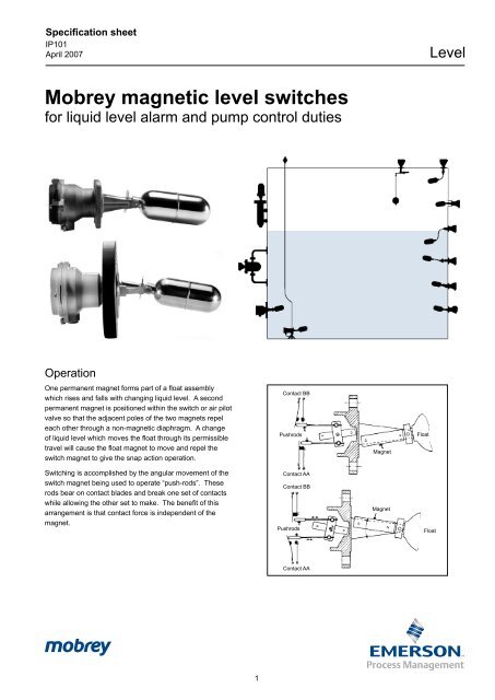
Specification sheetIP101April 2007 Level<strong>Mobrey</strong> <strong>magnetic</strong> <strong>level</strong> <strong>switches</strong>for liquid <strong>level</strong> alarm and pump control dutiesOperationOne permanent magnet forms part of a float assemblywhich rises and falls with changing liquid <strong>level</strong>. A secondpermanent magnet is positioned within the switch or air pilotvalve so that the adjacent poles of the two magnets repeleach other through a non-<strong>magnetic</strong> diaphragm. A changeof liquid <strong>level</strong> which moves the float through its permissibletravel will cause the float magnet to move and repel theswitch magnet to give the snap action operation.Contact BBPushrodsMagnetFloatSwitching is accomplished by the angular movement of theswitch magnet being used to operate “push-rods”. Theserods bear on contact blades and break one set of contactswhile allowing the other set to make. The benefit of thisarrangement is that contact force is independent of themagnet.Contact AAContact BBPushrodsMagnetFloatContact AA
ContentsPageThe complete horizontal float switch rangeOperationSwitch selection 4Alarm switching - electrical or pneumatic 4Pump control - electrical or pneumatic 4Low temperature applications 4Choice of switch mechanisms 5Electrical 5Pneumatic 5General purpose applications 6-7Aluminium bronze wetside modelsMarine applications 8-9Submersible - HoseproofGeneral purpose applications 0-11Stainless steel wetside modelsHazardous area applications 2-13Flameproof zone 1 gas group I & IIC modelsMarine hazardous area applications 4-15Submersible - HoseproofChemical applicationsP.T.F.E. wetside6Nozzle & stud lengths6Float chambers 7-19Fabricated chambersCast chambersFloat specifications 20-22Horizontal pump control floats 20Vertical pump control and alarm floats 20Cranked arm floats type and F104 21Companion flanges and accessories 23ATEXApplications 24
Switch selectionAlarm switching - Electrical or PneumaticHorizontal or vertical:High or low alarm <strong>switches</strong> are ofrobust construction, making them idealfor a wide range of liquids in industrialapplications.Dirty liquid applications:The shrouded model should be specified,thus eliminating fouling of the floatmovement due to deposits or largeparticles becoming wedged.Submersion:For those applictions where theequipment may be subject to occasionalor continuous submersion thesubmersible model should be specified.Hoseproof marine applications:Switches have been specifically designedfor the requirements of these markets& approval authorities, (for details ofapprovals contact the factory).Vacuum applications:All metallic floats are capable of operatingin full vacuum conditions.High alarmLow alarmHigh or lowalarmSubmersibleswitchViscous liquidsCranked arm float units should bespecified to enable the operatingmechanism to be kept clear of the liquid.Rod extensions shaped to individualrequirements are available to fit all<strong>Mobrey</strong> <strong>level</strong> <strong>switches</strong>.Pump control - Electrical or PneumaticHorizontal mounting:Vertical mounting:(a) Horizontal large differential, two (c) Vertical variable differential, controlled<strong>switches</strong> are used to control the pump by using one switch verticallyfor emptying or filling requirements. mounted and the appropriate(b) Horizontal limited differential,adjustable variable differential vertical(555mm maximum) can be controlled float unit.with one switch and a variabledifferential float unit.acPump onbaPump offLow temperature applications<strong>Mobrey</strong> <strong>level</strong> <strong>switches</strong> are suitable forbelow 0°C applications.Standard switch mechanisms typeD, P, D6, P6 may be specified for lowtemperature duty down to -30°C ambientand wetside, except in flameproof<strong>switches</strong>, when H6 must be specified,allowing use down to -60°C.Note: If the wetside temperature remainsbelow that of the switch enclosure forany extended period, then there is thepossibility of gradual build up of frozencondensation.This is due to the breathing which willnaturally occur through any degreeof enclosure protection (IP67 or less)and will eventually impair the correctmovement of the operating magnet. Toprevent this, we strongly recommendthe use of the hermetically sealed switchmechanism type H6, B6, suitable for usedown to -60° C ambient.Gasket Materials:<strong>Mobrey</strong> <strong>switches</strong> with flanges ANSI Class600, Class 900 and BS EN 1092-1PN64 are fitted with spiral wound nonasbestosfilled gaskets rated to 400°C.All other <strong>switches</strong> are fitted with nonasbestossheet material gaskets toBS 7531 Grade X, which has uppertemperture limits of 250°C for gas, vapour& steam, and 440°C for liquids. If theswitch will experience gas vapour orsteam temperatures above 250°C, then asuitable alternative gasket must be fitted.Cable gland:A cable gland is supplied in the box withthe S01DB, S179, Mini-switch, and S36range.It is a brass cable gland, nickel plated,with a fully insulated neoprene sealand with clamping range to suit 8mm to13mm OD cable.The cable gland has type IP68 protectionto 5m head of water(0.5 bar), and maximum 80 0 C as apermanent temperature on application.For submersible <strong>switches</strong> in applicationsgreater than 5m (0.5 bar) submersion,the fitting and testing of customerssupplied cable and gland is thecustomer’s responsibility.
General purpose applicationsStainless steel wetside models126S36DA/F84Weatherproof to IEC 144:IP66126S440DA/F84Specificationselectrical modelsBack flange (where fitted)Wetside materialEnclosure housing material:Carbon steel to BS 1501: 224 Grade 430B LT50. This material has guaranteedproperties at both high (400°C) and low (-50°C) temperatures.Painted surfaces are stove paint finish. All unpainted surfaces are corrosive protected.Stainless steel to type 316 to <strong>Mobrey</strong> standardStainless steel type 316S33 (S489 & S490 models only)Aluminium alloy to BS1490: Grade LM24air pilot valve modelsValve blockFinish:Aluminium alloy to BS 1490: Grade LM25 - chromate phosphate treated.All surfaces are chromate phosphate treated then externally stove painted.Maximum temperature dependent on switch mechanism, gasket and gland - see pages 4 and 5ApprovalsStock availabilityLloyds Register of ShippingGermanischer LloydCSADNVABSRMSALUDTModels availablefrom stockGeneral purposeS36DA/F84S36DA/F104/1S190DA/F93S428DA/F84S429DA/F84S440DA/F84S36DA/F68/1S36DA/F68/4S36DA/F21/1S36DA/F21/2S36DA/F21/3Other approvals available.Please contact us with your requirements.10
Ordering informationCODESGeneral purpose stainless steel wetside modelsSwitchCODE36190440441424425489490428429430431432417418419433434488435436437Flange (Head)Size<strong>Mobrey</strong> A<strong>Mobrey</strong> A3"4"3"4"3"3"DN 65DN 80DN 100DN 125DN 150DN 65DN 80DN 100DN 125DN 150DN 80DN 100DN 125DN 150CODEDPD6P6H6B6APAMSwitch mechanism4 Contact - General4 Contact - Gold plated contacts6 Contact - General6 Contact - Gold plated contacts6 Contact - Hermetically sealed6 Contact - Zone 2 areasPneumatic - On/OffPneumatic - ModulatingCODEARating33.8 bar33.8 bar150 RF150 RF300 RF300 RF600 RF900 RFPN 16PN 40PN 64Enclosure / HousingAluminium alloyCODE Float - Application informationF84 General purposeF96 High alarm orF98 Low alarm orF106 2 off for pumpF107 Control wide, differentialStandard<strong>Mobrey</strong><strong>Mobrey</strong> : Use float F93 onlyTo BS 1560orASMEIB 16.5BS EN 1092-1BS EN 1092-1BS EN 1092-1F68/+F21/+F104/+F88F93∨ ∨ ∨ ∨ ∨S36 D A / F84Pump control horizontalVertical : Pump control or alarmCranked arm : horizontal or verticalInterface dutyShrouded for dirty liquids (S190 only) Silicone rubber gaiter with 316SS shroud and float.+ Refer to pages 20, 21 and 22 for technical float details and length optionsRefer to page 16 for nozzle and stud lengths.Switch/float combination chartF No.S No.F84F96F98F106F107F68/+F21/+F104/+F88F93S36S190S417S418S419S424S425Notes: Preferred combination • Non-preferred combinationS428S429S430S431S432 • • • • • • • • • • • • •• • • • • • • • • • • • • • • • • • • • • • •• • • • • • • • • •• • • • • • • • • • • • • • • • • • • • • • • • • • • • • • • • • • • • • • • • • • • • • • • • • • • • • • • • • • • •S433S434S435S436S437S440S441S488S489S49011
Hazardous area applicationsFlameproof zone 1 gas group IIc modelsS250DA/F84Weatherproof to IEC 144: IP66Conduit entry threadGunmetal body 25mmAluminium body 20mmSpecificationsBack flange(where fitted)Wetside materialEnclosure/housingmaterialAmbient temperaturesbelow 0°CCarbon steel to BS 1501 : 224 : Grade 430B LT50. This material has guaranteed propertiesat both high (400°C) and low (-50°C) temperatures. Painted surfaces are stove paint finishwhilst all unpainted surfaces are corrosion protected.Stainless steel to type 316 to <strong>Mobrey</strong> standardStainless steel type 316S33 (S260 & S261 models only)Max. working temp*: Aluminium body 400°CGunmetal body 350°CGunmetal to BS 1400: Grade LG2.Max. working temp*: S275 200°CAluminium alloy to BS1490: LM25Finish is chromate phosphate treated and externally stove paintedGunmetal to BS1400: LG2Natural finishi) Down to -20° Cstandard enclosure/housing codes A or G are suitable.ii) Down to -60°CSpecify enclosure/housing codes AX or GX which are as standard but with ATEX certification touse to -60°C. Note : -50° C unless ‘G’ flange or low temperature back flange is specified.*See page 4 for gasket temperature limits.CertificationZone 1 Gas group IICSIRA / ATEXII 1/2 G, EExd IIC T6 (-20°C< Ta
Ordering informationCODE SSwitch for hazardous area applications, flameproof zone 1 gas group I and IIc modelsCODE Flange (head) size Rating Wetside250275256257278251254260261253255269272268270271<strong>Mobrey</strong> G<strong>Mobrey</strong> G3"4"6"3"4"3"3"DN 80DN 100DN 125DN 80DN 100DN 125DN 15021 bar21 bar150 RF150 RF150 RF300 RF300 RF600 RF900 RFPN40PN 64Stainless steelGunmetalTo BS 1560orASMEB 16.5BS EN 1092-1BS EN 1092-1CODEDPD6P6H6Switch mechanism4 Contact - General4 Contact - Gold plated contacts6 Contact - General6 Contact - Gold plated contacts6 Contact - Hermetically sealedNote: The ATEX certification coveringuse -20 o C to -60 o C ambient temperaturerequires the hermetically sealed switchmechanism type H6 to be fitted.CODEAGXEnclosure / HousingAluminium alloyGunmetalSuffix X must be specified for applications with ambient temperatures -20 o C to -60 o CCODEF84F185F98F106F107F96F68/+F264Float - Application informationGeneral purpose high alarms or low alarmsor 2 off for pump controlHorizontal pump controlHorizontal limited differentialF21/+F104/+F88Vertical pump control or alarmCranked arm: horizontal or verticalInterface duties∨ ∨ ∨ ∨ ∨S 251 D A / F96 Typical ordering information+ Refer to pages 20, 21 and 22 for technical float detailsRefer to page 16 for nozzle and stud lengths.Switch/float combination chartFNo.F84F185F98F106F107F68/+F21/+F104/+F88F96F264SNo.S250S275S256S257S278S251S254S260S261•••••••••••••••••••••• • • • • • • • • • • •• • • • • • ••••••••••••••••••••••••• • • • • • • • • • • • • • • • • • • • • • • • • • • • • • • • • • • • • • • • • • • • • • •S253S255S269S272S268S270S271 Preferred combination• Non-preferred combinationPopular combinationsS250DA/F84S250DA/F104/1S275DA/F84S275DG/F8413
Marine hazardous area applicationsSubmersible - Hoseproof - FlameproofZone 1FloatSwitchMax. head : 30 metresCustomer'smountingbracketInsidecustomer'svesselApplication A : Submersed, in vented tank application (II 2G)Outside customer'svesselGasket125FloatSwitchMax. tank pressure : 18 bar Zone 0Zone 1Application B : Outside, tank mounted application (II 1/2G)CertificationZone 1 Gas group IICATEX II 2 G, Exd IIC T6 (-20°C< Ta
Ordering informationCode Hazardous area, submersible, hoseproof & marine applicationsS SwitchCode Flange (head) Size Rating Standard183 <strong>Mobrey</strong> A 18 bar <strong>Mobrey</strong>187 <strong>Mobrey</strong> A 18 bar <strong>Mobrey</strong>189 <strong>Mobrey</strong> A 18 bar <strong>Mobrey</strong>Code Switch mechanismD 4 contact - generalP 4 contact - gold plated contactsD6 6 contact - generalP6 6 contact - gold plated contactsCode Enclosure housingB Aluminium bronzeCode CableL 3m fitted (applies to S183 and S187 only)Code Float - application informationF84 General purpose hir or low alarmF185 or 2 off for pump controlF68/+ Horizontal pump controlF21/+ Vertical pump control or alarmF264 Horizontal limited differentialF104+ Cranked arm vertical or horizontalF93 Shrouded for use with dirty liquids, silicone rubber gaiter with 316ssshroud & float S 183 D B L F84 Typical ordering information+ refer to pages 20, 21 and 22 for technical float details and lengths options.Refer to page 16 for nozzle and stud lengths.15
Chemical applicationsP.T.F.E. Wetside71S357D/F317S357P/F317SpecificationsType number S357D/F317 S357P/F317Switch mechanism General Gold platedHousing material Aluminium alloy Aluminium alloyWetside material PTFE PTFEFinish Chromate phos/painted Chromate phos/paintedIP rating IP66 IP66Notes:1. S357D <strong>level</strong> switch has a combined <strong>Mobrey</strong> A & E flange and may be used with either mounting flange.2. <strong>Mobrey</strong> offers a wide range of “Engineer to order” <strong>level</strong> <strong>switches</strong> for chemical applications with higher pressures ortemperatures. Consult factory for details.Stock availabilityModels available from stockS357D/F317S357P/F317Nozzle and stud lengthsMaximum nozzle length allowable (dimension 'A').Please refer to page 23 for companion flanges and accessories.FlangeFloatF68/+F84F185F88F93F96F98F106F107F264Minimum studprojectionA mm<strong>Mobrey</strong> ADN65DN80DN100DN125DN1503" 300 & 1504" 300 & 1503" 6003" 900<strong>Mobrey</strong> G6" 15065657095105224709562626522475758010514018080105707075-75758010514018080105707075-13513517020020020017020013013013520075-----------75758010514018080105707075-90909010514017090105858590-92929811014020098110898992----------118--75759010014019090100707075190Minimum stud projection (mm)RatingG A PN16 PN40 PN64 150 300 600 900Size--6580100 125150 6580100125150801001251503"4"3"4"3"3"Stud3530404040404442424652545255626746465456647416
Float chambersFabricated chambersCast chambersIntroductionFloat chambers are used to facilitate the external mounting of a<strong>Mobrey</strong> Magnetic <strong>level</strong> switch on to a tank or pressure vessel,particularly where space inside the vessel is restricted or wherethe control must be isolated for routine maintenance whilst theplant is in operation.A wide range of cast or fabricated chambers is available.Process connections may be specified top and bottom or sideand side, and can be flanged, screwed or butt welded in achoice of sizes to suit most plant installations.Exotic materials are also available.Standard finishBlack stove paint. 2 pack epoxy or hot dip galvanised availableat extra cost.Pressure testingAll chambers are full pressure tested at the relevant connectionflange test pressure.Operating pressureNote that the pressure/temperature ratings of the <strong>switches</strong> andchambers are not always compatible so that the lower rating willbe the governing factor in selection.Low temperature useThe lowest operating temperature for the fabricated carbon steelchambers is -7°C and the cast iron chambers is 0°C.If use at temperatures below these limits is required, LT50,LT100 or stainless steel can be specified.SelectionThe choice of chamber will depend on the type of <strong>Mobrey</strong>Magnetic <strong>level</strong> switch to be used and the form of connectionsrequired. For example, if S424DA/F96 is selected then a 145chamber can be used with the connections of your choice inrespect of pipe size, flange rating and connection arrangement.Features• Relevant chambers are supplied CE marked and fullycompliant with the Pressure Equipment Directive(97/23/EC)• Variety of connection configurations available.• Welding procedures approved to BSEN 288-3 & ASME IX• Welders approved to BSEN 287-1• All materials used for fabricated chambers are to ASMEspecifications• Material certification, BS. EN10204.3.1B• Chambers can be manufactured in a wide variety ofmaterials, including 321 and 316 stainless steel, IncoloyMonel, CrMo steels and other more exotic materials• Paint finish to customers specifications• Chambers may be supplied in accordance with NACErecommendations for sour service• NDT to CSWIP and ASNT is available for radiographic,ultrasonic, mag particle and dye penetrant• Customers and nominated inspection agencies arewelcome to witness pressure testing.• Switches and chambers are individually pressure tested atthe relevant flange test pressure. They are suppliedloosely assembled for transit and flange bolts must betightened on site before commissioning.17
Fabricated chamber dimensionsFabricated chambers Standard dimensions: Ref. only - must be certified on orderModelSw mounting flgPressureXYZModelSw mounting flgPressureXYZ144C145C148C151CANSI 3" # 150ANSI 3" # 300MOBREY 'A'MOBREY 'G'19.6 bar51 bar18 bar21 bar143143143143185185169169168168168168305C306C307C308CBSEN1092-1 DN80 PN64BSEN1092-1 DN65 PN40ANSI 3” Class 600ANSI 3” Class 90064 bar40 bar102 bar153 bar143143143143183162162164168168168168XYNominal ref. dimensionsØZProcess connectionsSwitch mountingflangeCast chambers Standard dimensions: Ref. only - must be certified on order802-S01DB/F84201 with drainage 802 without drainageTypeno.201802MaterialCast ironBS EN 1561Grade EN GJL 250BS EN 1561Grade EN GJL 250ProcessconnectionsScrewed 1” BSPBS EN 1092-1DN20 PN16Maximum workingconditions for chamberPressure Temp.13 bar at 210 o C13 bar at 210 o CSuitable <strong>Mobrey</strong> <strong>level</strong> <strong>switches</strong>Switch flange Typical combination<strong>Mobrey</strong> A 201-S01DB/F84<strong>Mobrey</strong> A 802-S01DB/F84DrainageWithWithoutMinimum working temperature 0 o C18
Fabricated chambers : ordering informationCode144C145C148C151C305C306C307C308CMaterial switch flangeCarbon steel/ANSI 3" Class 150Carbon steel/ANSI 3" Class 300Carbon steel/<strong>Mobrey</strong> 'A'Carbon steel/<strong>Mobrey</strong> 'G'Carbon steel/BS EN 1092-1 DN80 PN64Carbon steel/BS EN 1092-1 DN65 PN40Carbon steel/ANSI 3" Class 600Carbon steel/ANSI 3" Class 900max. Pressure 20°C19.6 bar51 bar18 bar21 bar64 bar40 bar102 bar153 barMax Temp °C400°C400°C400°C400°C400°C400°C400°C400°CSee page 4 for gasket limitsCODE1234567890Process connection styleSide & top or side & bottomSide & sideSide & top or side & bottomSide & top or side & bottomTop & bottomSide & top or side & bottomTop & bottom stub pipeTop & bottom threadolet or sockoletSide & sideSide & sideFlangedFlangedFlanged with ¾" flanged vent/drainFlanged with ¾" threaded vent/drainFlangedFlanged (close centres)Flanged with ¾" flanged vent/drainFlanged with ¾" threaded vent/drainCODE00010203040810111213151617181921222531323334353637Process connection size/rating1" NB Sockolet1" NPT threaded (female)1 ½" NPT threaded (female)2" NPT threaded (female)1" BSPT threaded (female)1" NB Sch 80 stub pipe2" NB Sch 80 stub pipeANSI 1" Class 150 RF weld neckANSI 1" Class 300 RF weld neckANSI 1" Class 600 RF weld neckBS EN 1092-1 DN25 PN16 RF weld neckBS EN 1092-1 DN25 PN25 RF weld neckBS EN 1092-1 DN25 PN40 RF weld neckBS EN 1092-1 DN25 PN64 RF weld neckBS EN 1092-1 DN25 PN100 RF weld neckANSI 1 ½" Class 150 RF weld neckANSI 1 ½" Class 300 RF weld neckBS 4504 DN 40 PN16 RF weld neckANSI 2" Class 150 RF weld neckANSI 2" Class 300 RF weld neckANSI 2" Class 600 RF weld neckANSI 2" Class 900 RF weld neckBS EN 1092-1 DN50 PN16 RF weld neckBS EN 1092-1 DN50 PN25 RF weld neckBS EN 1092-1 DN50 PN40 RF weld neckChamber options to customer order• Chambers can be manufactured ina wide variety of materials,including 321 & 316 stainless steel,Incoloy Monel CrMo steels &other more exotic materials.• Paint finish to customerspecifications.• NDT to CSWIP and ASNTis available for radiographicultrasonic, mag particle and dyepenetrant.• Chambers may be supplied inaccordance with NACErecommendations for sour service.∨ ∨ ∨145C / 5 12 Typical ordering informationDimBCD*EFH15021213910821260278Process connection sizes and dimensions for fabricated chambers1" DN25 1.5" DN40 2" DN50 Tolerance300218.5145.5112218.560291600225152.511722560305PN16196123-19660246PN25198125-19860250PN40198125-19860250PN100216143.5-21660287150218.5143.5108218.55428730022515011222554300PN16200125.5-2005425115022014410822048288300226150.511222648301600236161.5117--323900265190133--380PN16203127-20348254PN25206130-20648260PN40206130-20648260+000010-31.52213JScrewed Screwed/SW Screwed or socket weldNPT BSP NPT NPT240 240 244 2500 3* ¾” N.B. Vent/drain flange of relevant rating as shown. All dimensions shown are nominal and should be certified on order.19
Float specificationHorizontal f68 pump control and alarm floatS36DA/F68/4with rod cut to /3 dimensionSwitches fitted with F68 type float unit may be adjusted on site to meet pump control differential requirements.The float is available as a F68/1 or F68/4.The F68/4 has pre-drilled holes along the rod to allow the user to achieve the /2 and /3 differentials in the table below:Full details of the operating <strong>level</strong>s and differentials are in the manual. Note, these dimensions are approximate for cold water andwill vary for liquids of different SG.Maximum intrusionF68/1F68/2F68/3F68/4Wetside (mm) xMinimum SGMinimum tank dimension above/belowcentre line (mm)Maximum differential (mm)3600.722162474700.82923605900.823684836430.85406555Vertical F21 pump control and alarm floatLow <strong>level</strong> alarmNormal (left) andalarm positionsHigh <strong>level</strong> alarmNormal (left) andalarm positionsNote: Float assembly must be fitted from inside if for use in a vessel, or completeswitch and float assembly may be mounted on a suitable bracket or manhole cover.Pump controlLow <strong>level</strong> (left)and high <strong>level</strong>switching pointsFloat rod lengths available :F21/1: 1524mm (5')F21/2: 3048mm (10')F21/3: 4570mm (15') max.Float rods may be cut to length on site and <strong>switches</strong> set tooperate at required <strong>level</strong> in either pump control or alarm modeby following the setting instructions supplied.TypenumberPumpdifferential 'S'Alarm <strong>level</strong>sMinimum 'T' Maximum 'S'F21/* 13-4420* 172 4400** When maximum rod length specified20
21Vertically mounted <strong>switches</strong> V and W dimensions with relevant minimum specific gravityCranked arm floats F104Horizontally mounted <strong>switches</strong>A and B dimensions with relevant minimum specific gravityA0&75100125150175200225250275300325350375400425‘A’mm75.67.68.69.71100.67.68.70.71.73125.68.69.71.72.74.76.79150.68.70.71.73.75.77.80.83175.69.70.72.74.76.78.81.84.88.93200.69.71.73.75.77.79.82.85.88.93.98225.70.72.74.76.78.80.83.86.89.93.981.04250.71.73.75.77.79.81.84.87.90.93.981.031.09275.72.74.76.78.80.82.85.87.91.94.981.021.081.15300.73.74.76.78.81.83.86.88.91.95.981.031.071.131.20325.73.75.77.79.82.84.86.89.92.95.991.031.071.121.18350.74.76.78.80.83.85.87.90.93.961.001.031.071.12375.75.77.79.81.83.86.88.91.94.971.001.041.08400.76.78.80.82.84.87.89.92.95.981.011.04425.77.79.81.83.85.88.90.93.96.991.02450.78.80.82.84.86.89.91.94.96.99475.79.81.83.85.87.90.92.95.97500.79.81.84.86.88.90.93.95525.80.82.84.87.89.91.94550.81.83.85.88.90.92575.82.84.86.89.91600.83.85.87.89675.86650.85.87625.84.86.88For marine applicationBFor land applicationA0&75100125150175200225250275300325350375400425450475500525550575600625650675‘A’mm75.64.64.65.65.66.66.67.67.68.68.69.69.70.71.71.72.72.73.74.74.75.76.76.77.78100.64.65.66.67.67.68.69.69.70.71.71.72.72.73.74.74.75.76.77.77.78.79.80.80125.65.66.67.68.69.70.70.71.72.73.74.75.76.76.77.78.79.80.81.81.82.83.84150.66.67.68.69.70.71.72.73.74.75.76.77.78.79.80.81.82.83.85.86.87.88175.67.68.69.70.71.72.73.74.76.77.78.79.80.81.83.84.85.86.88.89.90200.67.69.70.71.72.73.75.76.77.78.80.81.82.83.85.86.87.89.90.92225.68.70.71.72.73.75.76.77.78.80.81.82.84.85.87.88.89.91.92250.69.70.72.73.74.76.77.78.80.81.83.84.85.87.88.90.91.93275.70.71.73.74.75.77.78.80.81.82.84.85.87.88.90.91.93300.71.72.74.75.76.78.79.81.82.84.85.87.88.90.91.93325.72.73.75.76.77.79.80.82.83.85.86.88.90.91.93350.73.74.75.77.78.80.81.83.85.86.88.89.91.92375.73.75.76.78.79.81.82.84.86.87.89.90.92400.74.76.77.79.80.82.84.85.87.88.90.92425.75.77.78.80.81.83.85.86.88.89.91450.76.78.79.81.82.84.86.87.89.90475.77.79.80.82.83.85.87.88.90500.78.79.81.83.84.86.88.89525.79.80.82.84.85.87.89550.80.81.83.85.86.88575.81.82.84.85.87600.81.83.85.86675.84650.83.85625.82.84.86BV75100125150175200225250275300325350375400425‘V’mm75.75.76.77.79100.72.72.72.72.71125.70.70.69.68.67.67150.69.68.67.67.67.68.68.69175.68.67.67.67.68.68.69.70.70200.68.68.68.68.68.69.70.70.71.71225.68.68.68.69.69.70.70.71.71.72.73250.68.68.69.69.70.70.71.71.72.73.73.74275.68.69.69.70.70.71.72.72.73.73.74.75.75300.69.70.70.71.71.72.72.73.73.74.75.75.76.77325.70.70350.71.71.72.72.73.73.74.74.75.76.76.77375.71.72.72.73.73.74.74.75.76.76.77.78.78400.72.73.73.74.74.75.75.76.76.77.78.78425.73.73.74.74.75.75.76.77.77.78.78450.74.74.75.75.76.76.77.77.78.79475.74.75.75.76.76.77.78.78.79500.75.76.76.77.77.78.78.79525.76.77.77.78.78.79.79550.77.77.78.78.79.79575.78.78.79.79.80600.79.79.80.80675.81650.80.81625.79.80.80For marine applicationFor intermediate dimensionsselect next longer size onchartWFor land applicationV75100125150175200225250275300325350375400425450475500525550575600625650675‘V’mm75.67.67.67.67.67.67.66.66.67.67.67.67.68.68.68.68.69.69.69.70.70.70.71.71.72100.67.66.66.66.66.66.66.66.66.67.67.67.67.67.68.68.68.69.69.69.70.70.70.71125.66.66.66.66.66.66.66.66.66.66.67.67.67.67.68.68.68.68.69.69.69.70.70150.66.66.66.66.66.66.66.66.67.67.67.67.67.67.68.68.68.68.69.69.69.70175.66.66.66.66.66.66.66.67.67.67.67.67.67.68.68.68.68.69.69.69.70200.66.66.66.66.66.67.67.67.67.67.67.68.68.68.68.68.69.69.69.70225.67.67.67.67.67.67.67.67.68.68.68.68.68.68.69.69.69.69.70250.67.67.67.67.67.68.68.68.68.68.68.69.69.69.69.69.70.70275.68.68.68.68.68.68.68.68.69.69.69.69.69.70.70.70.70300.68.68.68.69.69.69.69.69.69.69.70.70.70.70.70.71325.69.69.69.69.69.69.70.70.70.70.70.70.71.71.71350.70.70.70.70.70.70.70.70.71.71.71.71.71.71375.70.70.70.71.71.71.71.71.71.71.72.72.72400.71.71.71.71.71.72.72.72.72.72.72.72425.72.72.72.72.72.72.72.73.73.73.73450.73.73.73.73.73.73.73.73.73.74475.73.73.74.74.74.74.74.74.74500.74.74.74.74.75.75.75.75525.75.75.75.75.75.75.76550.76.76.76.76.76.76575.77.77.77.77.77600.77.77.78.78675.80650.79.79625.78.78.78WA + BMust not exceedV + W750mmA or VShould not be lessB or Wthan 75mm}}1. A and B or V and W dims.2 Liquid in contact3. Specific gravity of liquid4. <strong>Mobrey</strong> <strong>magnetic</strong> switch head‘B’min‘B’min‘W’ minFor intermediate dimensionsselect the next longer size onchart'W' mmFor straight arm float, suffix float number with ‘B’ dimension as requiredtype no. (eg. S01DB/F)5. State land or marine applicationHow to order: Specify - F104 float with:A + BMust notexceedV + W750mmA or VShould notbe lessB or Wthan 75mm}}.71.71.72.72.73.74.74.75.75.76.77.77.78.77.78
Floats for use with stainless steel wetside <strong>switches</strong>FloatTypeF84F96F98F106F107F68/+F21/+F104/+F88F93F317F185F264Min.S.G.0.650.600.450.510.710.72 to0.820.70Various0.8/1.00.750.70.670.85Max.Pressure at20°C (BAR)34.574.034.574.0200.034.530.034.574.0Atmospheric0.634.532.0Temperature°C Maximum40040040040040040040040040018060210210Differential(mm)131314131315 to 48313 to 4420-2613131323, 29 or 33Dimension XLength fromPrivot Point164164184185172294 to 522VariableAs ordered359183229164179DimensionYMaximumTravel119119127108120204 to 736-198124112119VariableDimension ZMax.ExternalDiameter656565656565129656565676563.5FloatMaterial316StainlessSteelPTFEMonelMonelXYØ Z<strong>Mobrey</strong> flangesFloat switch range<strong>Mobrey</strong>'A' flange4 off 14mm Øholes equispacedon 92mm PCDF84/F96F21/F22F104<strong>Mobrey</strong>'G' flange4 off 14mm Øholes equispacedon 98mm PCDF68F98F106F107F104F93Switch mechanismsBAD & P type D6, P6, H6 & B6 type AP & AM typeB1 A2 A3BAB3 B2 A1AA Makes on rising <strong>level</strong>A1 - A2 B1 - B3 Makes on rising <strong>level</strong>BAB1 A2 A3BABB Makes on falling <strong>level</strong>B3 B2 A1A1 - A3 B1 - B2 Makes on falling <strong>level</strong>22
AccessoriesTest devices for <strong>Mobrey</strong> 'A' flanged <strong>switches</strong> to facilitate mechanical testing of electrical circuit.cceadeabbTD 110/A(Sandwich)TD 111/A(Weld)TypeTD 110/ATD 111/AVessel flange<strong>Mobrey</strong> 'A'Weld onMax. pressurebar18*18*Max.temp. °C210210a7779b3564cØ mm142142d-92e6767(* 12.6 bar at max. temp 210°C)MaterialsTD 110/A TD 111/A316 Stainless Steel Carbon Steel STM A216 WCAFlourocarbon ElastomerFlourocarbon ElastomerCompanion flangesWelding and backing companion flanges are available as extra items to facilitate the direct mounting of <strong>Mobrey</strong> A and Gflange <strong>switches</strong>.'A' flange modelsWelding pad J184Welding nozzle J786Backing flange J863J184 in 316SS: 71020/107 (Not suitable with <strong>Mobrey</strong> ‘M’ switch SMA*) J863 in 316SS: 71030/900'G' flange modelsWelding pad J800Welding nozzle J799• All flanges manufactured inmild steel.• Backing flange zinc plated andpassivated.• Welding types suppliedcomplete with studs and nuts.• Backing type supplied withbolts, sealing washers and fullface gasket.• Welding Pad J800 in 316SS: 71020/111• Other materials available upon request.23
Specification sheetIP101February 2007 LevelApplicationsAlarm dutyPerhaps the most common application for the original <strong>Mobrey</strong> float switch is liquid <strong>level</strong>detection for alarm duty. Whether for high or low alarm, the “<strong>Mobrey</strong>” is one of the most reliableand cost effective instruments available today. Using the time proven principle of <strong>magnetic</strong>coupling, the switch is glandless, snap-acting and suitable for almost any liquid. Manufacturedwith a range of wetside materials and with a choice of electrical or pneumatic output, side or topmounting models have a tough IP66 weatherproof housing and are flange mounted to providethe “fit and forget” solution for liquid <strong>level</strong> alarm.Rugged, Reliable, Glandless, WeatherproofPump control<strong>Mobrey</strong> <strong>switches</strong> may be specified with pump control float mechanisms which can be siteadjusted to give control over the required liquid differential. Side mounting models operate over500mm – ideal for small header or filling tanks, and vertical mounting models with differentials upto 4500mm are commonly used in sumps and storage tanks.Side mount, Top mount, Site adjustableSubmersed applicationsIf it is not possible to side or top mount a switch, then specify the Submersible model. Thisswitch is watertight IP68 to 30m submersion, and may be tank floor mounted to provide low <strong>level</strong>alarm or pump cut-off/pump protection in sumps and pits. For heavily fouled liquids, a shroudedmodel is ideal as all the moving parts are protected inside an anti-fouling shroud. Switches maybe supplied with or without factory fitted and tested cable, with the option of Rubber or copperPyrotenax cable to suit.These models are also ideal for applications exposed to pressure hosing or occasionalsubmersion, and as such have become an industry standard for shipboard use.IP68 / 30m, Factory fitted cable, HoseproofHazardous area use - ATEX<strong>Mobrey</strong> <strong>switches</strong> are classed as simple switching apparatus and may be used in IntrinsicallySafe circuits when wired to a suitably protected supply. In these cases, specify Gold Platedcontacts which are suited to the low power in such circuits.A range of <strong>switches</strong> is also available with Flameproof (Explosionproof) approval, certified bymost of the world’s leading authorities.<strong>Mobrey</strong> certification covers use in all Gas GroupsPressures to 350bar and temperatures to 400 0 C are possible with <strong>Mobrey</strong> float <strong>switches</strong>.International approvals, High pressure, High temperatureChamber mountingIf it is required to mount the float switch outside of the main vessel, for example to facilitateisolation for routine maintenance or simply because the vessel is too small to accommodate thefloat, then specify a <strong>Mobrey</strong> chamber. Available in almost any conceivable shape and processconnection arrangement, chambers are designed, manufactured and tested in accordance withinternational standards. Approved welders will construct a chamber from the material of yourchoice, including Stainless, LT Carbon, Incalloy, Monel and High Chrome steels, certified andidentified to your instructions.Custom design, Coded construction, N.A.C.E.The Emerson logo is a trade mark and service mark of Emerson Electric Co.Rosemount is a registered trademark of Rosemount Inc.<strong>Mobrey</strong> is a registered trademark of <strong>Mobrey</strong> Ltd.All other marks are the property of their respective ownersWe reserve the right to modify or improve the designs or specifications of product and services at any time without notice.International:Emerson Process Management<strong>Mobrey</strong> Measurement158 Edinburgh Avenue, Slough,Berks UK SL1 4UET +44 (0)1753 756600F +44 (0)1753 823589www.mobrey.comAmericas:Emerson Process ManagementRosemount Inc.8200 Market BoulevardChanhassen, MN USA 55317T (US) (800) 999-9307T (International) 952) 906-8888F (952) 949-7001www.rosemount.comabcdefLiterature reference number : IP101 April 200724