easylab be-lcd-01 - TROX
easylab be-lcd-01 - TROX
easylab be-lcd-01 - TROX

Create successful ePaper yourself
Turn your PDF publications into a flip-book with our unique Google optimized e-Paper software.
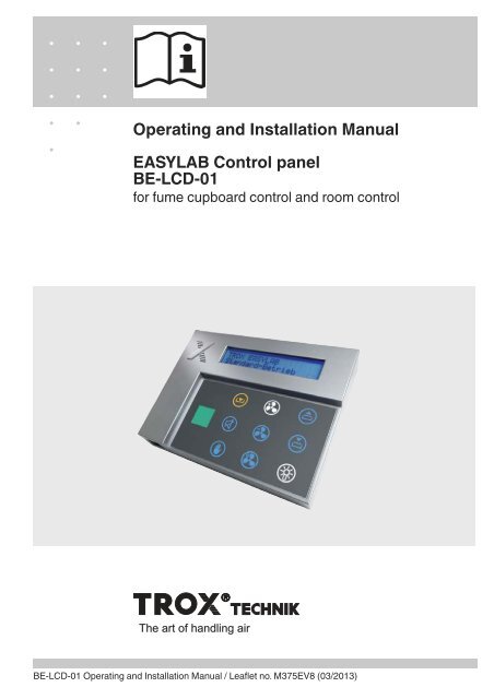
Operating and Installation ManualEASYLAB Control panelBE-LCD-<strong>01</strong>for fume cupboard control and room controlThe art of handling airBE-LCD-<strong>01</strong> Operating and Installation Manual / Leaflet no. M375EV8 (03/2<strong>01</strong>3)
Contents1 General information __________________ 3Other applicable documentation ________ 3Symbols used in this manual ____________ 32 Safety and correct use ________________ 4General information regarding safety ______ 4General safety measures ______________ 4Correct use ________________________ 4Incorrect use ________________________ 4Residual risks ______________________ 43 Product description __________________ 5Product overview and dimensions ________ 5Functional description and technical data __ 64 Transport, storage and packaging ________ 75 Operation · Fume cupboard control ______ 7Fume cupboard control ________________ 7Basic functions ______________________ 8Additional functions __________________ 9Operating mode default setting __________ 9Automatic sash device ________________ 10Fume cupboard lighting ________________ 10Overriding operating mode defaults setby the central BMS____________________ 10Operating states, alarm messages,fault displays ________________________ 115 Operation · Room control ______________ 14Room control ________________________ 14Basic functions ______________________ 15Additional functions __________________ 16Operating mode default setting __________ 16Overriding operating mode defaults setby the central BMS____________________ 17Operating states, alarm messages,fault displays ________________________ 18Mounting __________________________ 216 Installation and electrical wiring __________ 21Mounting on an adapter ________________ 22Wall installation using a junction box ______ 22Installation to a wall or to furniture ________ 237 Commissioning ______________________ 248 Maintenance ________________________ 24<strong>TROX</strong> GmbHHeinrich-Trox-PlatzD-47504 Neukirchen-VluynPhone +49 (0) 28 45 20 20Fax +49 (0) 28 45 20 22 65E-Mail trox@trox.dewww.troxtechnik.comSubject to change / All rights reserved © <strong>TROX</strong> GmbH2BE-LCD-<strong>01</strong> Operating and Installation Manual / Leaflet no. M375EV8 (03/2<strong>01</strong>3)
1 General informationThis operating manual descri<strong>be</strong>s the EASYLABBE-LCD-<strong>01</strong> control panel for fume cupboard controland room control.To ensure complete functioning of the control panelit is essential to read this operating and installationmanual <strong>be</strong>fore starting any work, and to complywith it. The manual must <strong>be</strong> given to the facilitiesmanager when handing over the system. Thefacilities manager must include the manual withthe system documentation.The manufacturer does not accept any liabilityfor any malfunction or damage resulting fromnon-compliance with these instructions or noncompliancewith relevant statutory regulations.Other applicable documentationIn addition to this manual, the following documentsapply:• Control Systems catalogue– EASYLAB BE-LCD-<strong>01</strong> control panel– EASYLAB TCU3 controller– EASYLAB TAM adapter module• EASYLAB Configuration Software OperatingManual (M375EV1)• Project-specific wiring documentsSymbols used in this manualDanger!Designates danger to life and limb due toelectrical voltage.Warning!Designates danger to life and limb.Important!Designates danger that can cause minorpersonal injury or damage to property.BE-LCD-<strong>01</strong> Operating and Installation Manual / Leaflet no. M375EV8 (03/2<strong>01</strong>3) 3
2 Safety and correct useGeneral information regarding safetyOnly skilled qualified personnel are allowed toperform the descri<strong>be</strong>d work on the control panel.Only skilled qualified electricians are allowed towork on the electrical system.For all work performed on EASYLAB components,the following regulations and guidelines must <strong>be</strong>complied with. This applies in particular to thefollowing German country specific regulations oras appropriate in the country where the installationis taking place:• Equipment and Product Safety Laws (GPSG)• Industrial Health and Safety Regulations(BetrSichV)• Accident Prevention Regulations (BGV A1,BGV A3)General safety measures• Large temperature differencesCondensation can damage the electronics<strong>be</strong>yond repair. If the control panel has <strong>be</strong>enkept in an unheated area, wait at least twohours <strong>be</strong>fore switching on the supply voltagefor commissioning.• Electrostatic chargeElectrostatic charge can damage the electronics.To avoid this, first touch an equipotentiallybonded metal surface, e.g. a water pipe, forelectrical earthing <strong>be</strong>fore you remove the controlpanel from its protective wrapping.• Fixing the base plate and the adapterTighten the screws only hand-tight in order to notdamage the base plate or the adapter.• Foreign matter and liquidsIf liquid gets inside the control panel, letthe control panel completely dry <strong>be</strong>forecommissioning. Remove foreign matter, if any.If the device emits a smell or smoke, have itchecked by the manufacturer.Correct useThe BE-LCD-<strong>01</strong> control panel is an EASYLABcomponent intended for the display of values andfor performing various functions. If the control panelis connected to a fume cupboard controller, thefunction display complies with EN 14175; operatingfunctions and special functions can <strong>be</strong> set bythe user. If a room is equipped with EASYLABcontrollers, the control panel is intended formonitoring and for operating mode default setting.• Connect the control panel to an EASYLAB TCU3used for fume cupboard control (equipmentfunction FH-xxx).• Connect the control panel to a EASYLAB TCU3controller used for extract air control (equipmentfunction RE), supply air control (equipmentfunction RS), or room pressure control(equipment function PC).• Connect the control panel to an EASYLAB TAMadapter module with active room managementfunction (RMF).• Surface mount the control panel onto the sideframe of the fume cupboard.• As an alternative, mount the control panel to awall, with our without junction box.• Observe the technical data for the control panel.Incorrect useDo not use the control panel outdoors, in wet areas,or in potentially explosive atmospheres.Residual risksA failure of the supply voltage is indicated on thecontrol panel only if the EASYLAB controller isequipped with the EM-TRF-USV expansion moduleand the battery pack has <strong>be</strong>en connected and fullycharged.4 BE-LCD-<strong>01</strong> Operating and Installation Manual / Leaflet no. M375EV8 (03/2<strong>01</strong>3)
3 Product descriptionProduct overview and dimensionsProduct overview1234567891 40-character display2 Alarm sounder3 Sash monitoring warning display4 Status display (green, yellow, red)with text HIGH and LOW5 Connection socket for service andcommissioning device6 Acoustic alarm acknowledgement7 Manual control8 Selection of operating mode9 Lighting or other equipment (RMF) Automatic sash device (FH),sun protection, e.g. blinds (RMF) Connection socket for EASYLABcontroller (on rear)DimensionsFront viewBE-LCD-<strong>01</strong>with adapterBE-LCD-<strong>01</strong>without adapter551111714515°≈6<strong>01</strong>0 28BE-LCD-<strong>01</strong> Operating and Installation Manual / Leaflet no. M375EV8 (03/2<strong>01</strong>3)5
3 Product descriptionFunctional description and technical dataFunctional descriptionThe BE-LCD-<strong>01</strong> control panel is used to displayand control the most critical aerodynamic functionsof a fume cupboard or a room. Users obtaininformation regarding the condition of the fumecupboard or room and can select among variousoperating modes. The individual display elementsand controls are as follows:• Three-colour status display• Warning display• 40-character display• Alarm sounder• Eight function button fields– Acoustic alarm acknowledgement– Three operating mode buttons– Two buttons for the automatic sash device orsun protection (depending on application)– One button for the fume cupboard lighting– One button for manual control• Service socketThe range of functions of the control panel can <strong>be</strong>adapted to project-specific requirements using theEasyConnect configuration software. The range offunctions may vary for different fume cupboards orrooms.The function button fields are used for display andas buttons for operation.The available functions are highlighted (blue).The required function can <strong>be</strong> selected by pressingthe appropriate button.• Selection of the operating mode• Automatic sash device• Control of the fume cupboard lightingThe 40-character display shows system messagesor, if enabled, current values.The control panel is connected to the EASYLABcontroller using a plug-in connection cable.The control panel consists of a front panel with thedisplay elements and controls, the electronics, andthe pluggable adapter that provides four differentviewing angles. The control panel can <strong>be</strong> mountedonto the side frame of a fume cupboard (using theadapter) or to a wall or furniture.The control panel is part of the EASYLAB system.The functions descri<strong>be</strong>d in this manual are onlyavailable with the corresponding controllers andpossibly additional components.Detailed information on design and areas ofapplication can <strong>be</strong> found on our website and inthe LABCONTROL design manual.Technical dataSupply voltageConnecting cableAcceptable temperature rangeAcceptable humidity for storage andoperationProtection levelDimensionsStructural depthCasing24 V AC/DC from TCU3 controller or TAM adapter moduleApprox. 5 m standard network patch cable, SF-UTP, extendable to 40 mfor storage: -10°C to +70 °Cfor operation: 0°C to +50 °C
4 Transport, storage and packaging5 Operation · Fume cupboard controlDelivery checkCheck delivered items immediately after arrival fortransport damage and completeness. In case of anydamage or an incomplete shipment, inform theshipping company and your <strong>TROX</strong> contact personimmediately.A complete shipment includes:• BE-LCD-<strong>01</strong> control panel with adapter• Connecting cable, approx. 5 m, patch cable, blue• Operating and installation manualTransport on site• If possible, take the control panel in the transportpackaging up to the installation location.• Do not remove the protective wrapping until just<strong>be</strong>fore installation.The BE-LCD-<strong>01</strong> control panel is used todisplay and control the most critical aerodynamicfunctions of a fume cupboard controlled by anEASYLAB TCU3 fume cupboard controller.The range of functions can <strong>be</strong> configuredindividually. The control panel has eightfunction button fields that are visible ornot visible according to the configuration.• Available function: blue symbol• Active function: white symbolStorageIf you need to store the control panel temporarily,make sure that the following conditions apply:• Leave the unit in its packaging and do not exposeit to the effects of weather.• Store the unit in a dry place and away from directsunlight.• Temperature: –10°C to +70°CMaximum humidity: 90% (non-condensing)PackagingProperly dispose of packaging material.The basic functions are available for all fumecupboards. Other functions may <strong>be</strong> availabledepending on the configuration and operatingstate.Fume cupboard controlThe BE-LCD-<strong>01</strong> control panel fulfils therequirements of EN 14175 for fume cupboardoperation and status displays.It can <strong>be</strong> used to control an automatic sashdevice as well as fume cupboard lighting. It worksin combination with the ‘fume cupboard controlequipment function of the TCU3 EASYLABcontroller and displays regular operating statesand values.Fume cupboard controlMTCU3BE-LCD-<strong>01</strong>BE-LCD-<strong>01</strong> Operating and Installation Manual / Leaflet no. M375EV8 (03/2<strong>01</strong>3)7
5 Operation · Fume cupboard controlBasic functionsThree-colour status displayGreen, yellow, red combined with text LOW andHIGH• GreenNormal operation, fume cupboard functionallyreliable• YellowVolume flow rate too high; fume cupboard isfunctionally reliable, increased energyconsumption• RedVolume flow rate too low; fume cupboard notfunctionally reliable, work at the fume cupboard isnot allowedGreen Yellow Red40-character status displayText display offume cupboardoperating statesand faults. Displaytexts → p. 11onwardsThe display ofadditionalinformation can <strong>be</strong> configured.• Volume flow rate setpoint and actual values• Face velocity actual value(only for fume cupboard controllers withface velocity transducer FH-VS)• Display text language• Unit of measure for volume flow rate setpoint andactual valuesThe display can <strong>be</strong> adjusted using the configurationsoftware.Acoustic alarm acknowledgementThis button is used to acknowledge andreset an acoustic alarm.Warning display for sash opening• Permanent lightMaximum operational sash opening has <strong>be</strong>enexceeded. At the same time, anacoustic alarm may sound(depending on the controllerconfiguration). The permanent lightis reset by closing the sash.• Blinking lightThe fume cupboard is affected by diversitycontrol. The volume flow rate has <strong>be</strong>en reducedto prevent the total room extract airfrom exceeding the set value.Close the sash.8 BE-LCD-<strong>01</strong> Operating and Installation Manual / Leaflet no. M375EV8 (03/2<strong>01</strong>3)
5 Operation · Fume cupboard controlAdditional functionsDepending on the configuration and operatingmode default setting additional displays andfunction buttons may <strong>be</strong> available.Available function buttons are visible (highlightedin blue or white). Function buttons that are notavailable are not visible.ExamplesWhite symbolThe function is active. Pressing the button againdeactivates the function.Blue symbolThis function is available but not active.Pressing the button activates thefunction.Non-visible (grey) symbolThe function is not available. This depends on theconfiguration of the controller or on thecurrent operating state.White symbol blinksIncreased operationOPEN mode (special operating mode) is active.White symbol -blinks after button has <strong>be</strong>enpressedIf you press a function button field and the whitesymbol blinks briefly, the selected function cannot<strong>be</strong> deactivated at the moment. The currentoperating mode default setting is ofhigher priority and cannot <strong>be</strong> overriddenon the fume cupboard.Operating mode default settingIn standard mode all function button fields for allavailable functions are indicated as blue symbols(i.e. not active). Activate the special operatingmodes using the following buttons:Activate increased operationPressing this button activates the increased volumeflow rate set for the controller (e.g. foremergency operating mode). Thesymbol colour changes to white.Activate reduced operationPressing this button activates the reduced volumeflow rate set for the controller (e.g. for nightsetback). The symbol colour changesto white.Shut-offPressing this key activates shut-off.The symbol colour changes to white.Deactivating special operatingmodesPressing the respective button deactivates thespecial operating mode. To select a new operatingmode without first deactivating the previous functionjust press the corresponding function button.Increased operation can <strong>be</strong> set for a limitedperiod of time. The increased volume flow will thenautomatically <strong>be</strong> deactivated after the set delay.BE-LCD-<strong>01</strong> Operating and Installation Manual / Leaflet no. M375EV8 (03/2<strong>01</strong>3)9
5 Operation · Fume cupboard controlOverriding operating mode defaults setby the central BMSOperating mode default settings from the centralBMS or from the room control panel can <strong>be</strong>overridden on the control panel for the fumecupboard controller.Temporary overrideA centrally set operating mode can <strong>be</strong> temporarilyoverridden at any time using the operating modebutton on the control panel. The operating modeselected on the control panel remains active untilthe central BMS sets another operating mode. If thecentral BMS sets a different default operatingmode, it overrides the locally activated operatingmode.Manual control for permanent overrideA centrally set operating mode can <strong>be</strong>permanently overridden on the controlpanel. To do so, first activate manualcontrol by pressing the correspondingbutton to prevent further overrides fromthe central BMS. Then set any other operatingmode on the control panel.This operating mode default setting can <strong>be</strong>terminated by pressing the manual control buttonagain. The fume cupboard controller then resumesthe previous operating mode from the central BMS.Manual operation can <strong>be</strong> set for a limited period oftime. The manual mode will then automatically <strong>be</strong>deactivated after the set delay and the previousoperating mode will <strong>be</strong> resumed.No override optionThe central BMS can suppress overrides from thecontrol panel temporarily or permanently. In thiscase, manual control cannot <strong>be</strong> used, and thecontrol panel shows only the centrally set operatingmode. If a user attempts to change the operatingmode on the control panel, the active operatingmode will blink briefly.Automatic sash deviceThese buttons are used to control the automaticsash device.The buttons can <strong>be</strong> used only if an automatic sashdevice has <strong>be</strong>en configured.Open the sashClose the sash.Fume cupboard lightingThis button is used to control the fumecupboard lighting.The button can <strong>be</strong> used only if thisfunction has <strong>be</strong>en configured.10BE-LCD-<strong>01</strong> Operating and Installation Manual / Leaflet no. M375EV8 (03/2<strong>01</strong>3)
5 Operation · Fume cupboard controlOperating states, alarm messages, fault displaysOperating statesCode State Actual state, explanation Actions, remedial measuresPFUPS, batteryoperationThe connected power supply has failed. The controlis maintained by the battery pack.Eliminate the cause of the powerfailure.SEServiceService (maintenance) for the fume cupboardcontrol is due.Initiate maintenance and have themaintenance interval reset.ooFume scrub<strong>be</strong>rdemandA user has requested the extract air scrub<strong>be</strong>r. Thevolume flow rate is increased as a consequence.When the set volume flow rate has <strong>be</strong>en reached,extract air scrubbing starts.00Fume scrub<strong>be</strong>ractiveThe increased volume flow rate for the extract airscrub<strong>be</strong>r has <strong>be</strong>en achieved. The extract airscrub<strong>be</strong>r is in operation.EFFire Open FireShut-offThe sensor system has activated smoke extract.Depending on the controller configuration thedamper blade will remain open or will <strong>be</strong> shut(shut-off).SCAutomatic sashdeviceError message relating to the automatic sash device.S1Test functionThe general test function, triggered by theconfiguration software, is active, e.g. actuator test.¹Sash opening> max.The maximum operational sash opening has <strong>be</strong>enexceeded.Close the sash.²ClosefumehoodMotion detector – indicates that the sash has to <strong>be</strong>closed.The sash is open and the motion detector has notdetected a person in front of the fume cupboardduring the set delay.Close the sash.²FaceVelocityreducedMotion detector – lower the face velocity to 0.3 m/s.The motion detector has not detected a person infront of the fume cupboard during the set delay.The face velocity has <strong>be</strong>en reduced.³Diversity limitationThe diversity control in combination with theroom management function is active.The volume flow rate of the fume cupboard isreduced based on the total room extract air.Close the sash.¹ Warning display permanently on ² Acoustic signal³ Warning display blinksBE-LCD-<strong>01</strong> Operating and Installation Manual / Leaflet no. M375EV8 (03/2<strong>01</strong>3) 11
5 Operation · Fume cupboard controlOperating states, alarm messages, fault displaysAlarm messagesCode State Explanation Actions, remedial measuresA1Volume flowrate too highThe volume flow rate exceeds the setpoint value.Check the actuator and thecontroller.A2Volume flowrate too lowThe volume flow rate falls short of the setpoint value.Check the pressure. Check thevolume flow rate transducer.A3 Face velocity The face velocity falls short of the threshold value.Check if the sash opening is toowide. Check the volume flow rate.Check the pressure.Configuration faultsCode Message Explanation Actions, remedial measuresC1C2SoftwareversionNo. ofcontrollers> 24Not all controllers have the same software versioninstalled.More than 24 controllers have <strong>be</strong>en connected to thecommuncation cable.Have the correct softwareversion installed by the Servicedepartment.Reduce the num<strong>be</strong>r of controllers.C3CommunicationcableterminationThe communication cable has not <strong>be</strong>en terminatedproperly. An active terminal resistor is required ateach end of the communication cable.Activate the terminal resistorsusing a switch on the EASYLABTCU3 main PCB.C4RMFconfigurationThe room management function has not <strong>be</strong>enactivated on any of the controllers.Activate the RMF on a controller.C5dP controller ≠1Configuration of differential pressure control isincomplete. There is either no differential pressurecontroller on the communication cable, or the roommanagement function is not active.Include a differential pressurecontroller. Activate differentialpressure control in the roommanagement function.C6SystemconflictNot all controllers are of the same system type.Connect either supply aircontrollers or extract air controllersbut not both.12BE-LCD-<strong>01</strong> Operating and Installation Manual / Leaflet no. M375EV8 (03/2<strong>01</strong>3)
5 Operation · Fume cupboard controlOperating states, alarm messages, fault displaysController faultsCode Message Explanation Actions, remedial measuresH124 VundervoltageThe supply voltage is too low. The sensors andactuators are no longer supplied with sufficientpower.Check the power supply to thesystem.H2AIcharacteristicAnalogue input signal is outside of the characteristic.Check the voltage signal orsensor. Check the characteristicparameters stored in thecontroller.H3Supportiveflow fan faultThe feedback signal from the supportive flow fan ismissing. The fan has <strong>be</strong>en switched off, or the cableis no longer connected. The controller automaticallyraises the volume flow rate to the value that has <strong>be</strong>enset for this case.Check the feedback signal and thesupportive flow fan.Control panel faultsCode Message Explanation Actions, remedial measuresE1ConnectionlostCommunication <strong>be</strong>tween the control panel and thefume cupboard controller has <strong>be</strong>en interrupted.For technical reasons, this text always appears inEnglish.Check the cable connection, thecontrol panel, and the controller.E2CP-CRCfailureCommunication <strong>be</strong>tween the control panel andthe fume cupboard controller is faulty. For technicalreasons, this text always appears in English.Check the cable connection, thecontrol panel, and the controller.E3CP notpossibleThe control panel cannot <strong>be</strong> used with the controllerto which it is connected. The control panel must <strong>be</strong>connected to a configured fume cupboard controlleror to a controller with active room managementfunction.Check the wiring, assignment, andconfiguration.E4CP memoryA hardware error occurred while accessing theinternal memory.If the error occurs again, replacethe control panel.BE-LCD-<strong>01</strong> Operating and Installation Manual / Leaflet no. M375EV8 (03/2<strong>01</strong>3) 13
5 Operation · Room controlThe BE-LCD-<strong>01</strong> control panel is used to displayand control the most critical aerodynamic andsafety-related functions of an EASYLABcontrolled room.The range of functions can <strong>be</strong> configuredindividually. The control panel has eightfunction button fields that are visible ornot visible according to the configuration.• Available function: blue symbol• Active function: white symbolThe basic functions are available for allfume cupboards. Other functions may <strong>be</strong>available depending on the configurationand operating state.Room controlFor setting operating modes and for monitoring anentire room the control panel is to <strong>be</strong> connected toa TCU3 supply or extract air controller, or to theTAM adapter module with active room managementfunction.Consolidated faults as well as pressure controlstates can <strong>be</strong> displayed.Room controlSupply airExtract airBE-LCD-<strong>01</strong>CommunicationcableFume Fumecupboard 1 cupboard n14BE-LCD-<strong>01</strong> Operating and Installation Manual / Leaflet no. M375EV8 (03/2<strong>01</strong>3)
5 Operation · Room controlBasic functionsThree-colour status displayGreen, yellow, red combined with text LOW andHIGHGreen Yellow RedAcoustic alarm acknowledgementThis button is used to acknowledge andreset an acoustic alarm.Warning: Diversity control is active• Blinking displayThe fume cupboards are affected bydiversity control. The volume flow ratehas <strong>be</strong>en reduced for some fumecupboards to prevent the total roomextract air from exceeding the setvalue.Close the sash.Volume flow rate control - functional display• GreenStandard operation, no errors• YellowToo many sashes are open. The set threshold forthe room total extract air has <strong>be</strong>en exceeded;diversity control is active.• RedAn error has occurred, or the SHUT-OFF orOPEN operating mode is active. The cause is<strong>be</strong>ing displayed.Pressure control - functional display• GreenStandard operation, normal room pressure• YellowThe differential pressure is too high.For negative pressure: Room pressure is too low.For positive pressure: Room pressure is too high.• RedAn error has occurred, or the differential pressureis too low.For negative pressure: Room pressure is too high.For positive pressure: Room pressure is too low.40-character status displayThe display shows certain operating states for theroom as well aserror codes. Ifroom control isactive, roompressure actualand setpointvalues are alsodisplayed.Display texts →p. 18 onwardsThe display of additional information can <strong>be</strong>configured.• Volume flow rate setpoint and actual values• Total room extract air actual and setpoint values• Display text language• Unit of measure for volume flow rate setpoint andactual valuesThe display can <strong>be</strong> adjusted using the configurationsoftware.BE-LCD-<strong>01</strong> Operating and Installation Manual / Leaflet no. M375EV8 (03/2<strong>01</strong>3) 15
5 Operation · Room controlAdditional functionsDepending on the configuration and operatingmode default setting additional displays andfunction buttons may <strong>be</strong> available.Available function buttons are visible (highlightedin blue or white). Function buttons that are notavailable are not visible.ExamplesWhite symbolThe function is active. Pressing the button againdeactivates the function.Operating mode default settingIn standard mode all function button fields for allavailable functions are indicated as blue symbols(i.e. not active). Activate the special operatingmodes with the following buttons.Activate increased operationPressing this button activates theincreased volume flow rates set for allcontrollers in the room (e.g. foremergency operating mode). Thesymbol colour changes to white.Blue symbolThis function is available but not active.Pressing the button activates thefunction.Non-visible (grey) symbolThe function is not available. This depends on theconfiguration of the controller or on thecurrent operating state.White symbol blinksIncreased operationOPEN mode (special operating mode) is active.White symbol - blinks after buttonhas <strong>be</strong>en pressedIf you press a function button field and the whitesymbol blinks briefly, the selected function cannot<strong>be</strong> deactivated at the moment. The currentoperating mode default setting is ofhigher priority and cannot <strong>be</strong>overridden on the fume cupboard.Activate reduced operationPressing this button activates the reduced volumeflow rates set for all controllers in the room (e.g. fornight setback). The symbol colourchanges to white.Shut-offPressing this key activates theSHUT-OFF mode for all controllers in the room.The symbol colour changes to white.Deactivating special operatingmodesPressing the respective button deactivatesthe special operating mode. To select anew operating mode without first deactivating theprevious function just press the correspondingfunction button.Increased operation can <strong>be</strong> set for a limited period.This enables an automatic deactivation of theincreased operation after the set delay.NoteWhether a defaulted operating mode applies to acontroller in a room depends on the configuration ofthe controller and on whether manual control isactive on each fume cupboard.16BE-LCD-<strong>01</strong> Operating and Installation Manual / Leaflet no. M375EV8 (03/2<strong>01</strong>3)
5 Operation · Room controlOverriding operating mode defaults setby the central BMSOperating mode default settings from the centralBMS can <strong>be</strong> overridden on the control panel for theroom.Overriding the room operating modetemporarilyA centrally set room operating mode can <strong>be</strong>temporarily overridden at any time using theoperating mode button on the control panel. Theoperating mode selected on the room control panelremains active unless the central BMS sets anotheroperating mode. If the central BMS sets a differentdefault operating mode, that operating modeoverrides the locally activated operating mode.The operating mode for all room controllers isalways the operating mode that has <strong>be</strong>en set last,either by the central BMS or on the room controlpanel.Overriding the room operating modepermanently using manual controlA centrally set room operating modecan <strong>be</strong> permanently overridden on theroom control panel. To do so, activatemanual control by pressing thecorresponding button. This preventsfurther overrides by the central BMS. You can thenset any other operating mode using the controlpanel.To resume the previous operating mode from thecentral BMS, press the manual mode button again.Manual operation can <strong>be</strong> set for a limited period.The manual mode will then automatically <strong>be</strong>deactivated after the set delay, and the previousoperating mode will <strong>be</strong> resumed.No override option for the room operatingmodeThe central BMS can <strong>be</strong> configured to blockthe override function on the room control paneltemporarily or permanently. In this case, manualcontrol cannot <strong>be</strong> used, and the control panelshows only the centrally set operating mode. If auser attempts to change the operating mode onthe control panel, the active operating mode willblink briefly.LightingUse this button to switch the room lighting on or off.This function is only available if theroom management function has <strong>be</strong>enconfigured accordingly.This button can also <strong>be</strong> used for otherfunctions instead of or in addition toswitching the lighting on/off, e.g. for switchingcertain devices on/off.Sun protection (e.g. blinds)Use these buttons to operate the sun protection,e.g. blinds (by others).These buttons are available only if this function has<strong>be</strong>en set for the control panel (configuration of theroom management function).Open blindsClose blindsBE-LCD-<strong>01</strong> Operating and Installation Manual / Leaflet no. M375EV8 (03/2<strong>01</strong>3) 17
5 Operation · Room controlOperating states, alarm messages, fault displaysOperating statesCode State Actual state, explanation Actions, remedial measuresPFUPS, batteryoperationThe connected power supply has failed. The controlis maintained by the battery pack.Eliminate the cause of the powerfailure.S1Test functionThe general test function, triggered by theconfiguration software, is active, e.g. actuator test.³ Diversity activeToo many sashes are open. The set threshold for theroom total extract air has <strong>be</strong>en exceeded; diversitycontrol is active. The volume flow rate has <strong>be</strong>enreduced for some fume cupboards.Close some sashes.³ Door switchThe door contact is active and affects pressurecontrol.¹ Warning display permanently on ² Acoustic signal³ Warning display blinksAlarm messagesCode State Explanation Actions, remedial measuresA1Volume flowrate too highThe volume flow rate exceeds the setpoint value.Check the actuator and thecontroller.A2Volume flowrate too lowThe volume flow rate falls short of the setpoint value.Check the pressure. Check thevolume flow rate transducer.A4Σ extract air istoo highThe set threshold for the room total extract air has<strong>be</strong>en exceeded; diversity control is active.Close some sashes.A5Differentialpressure is toohighThe differential pressure is too high.For negative pressure: Room pressure is too low.For positive pressure: Room pressure is too high.A6Differentialpressure is toolowThe differential pressure is too low.For negative pressure: Room pressure is too high.For positive pressure: Room pressure is too low.A7Σ extract air istoo lowThe total room extract air falls short of the setthreshold for the total room extract air.Check the pressure. Check thevolume flow rate transducer.18BE-LCD-<strong>01</strong> Operating and Installation Manual / Leaflet no. M375EV8 (03/2<strong>01</strong>3)
5 Operation · Room controlOperating states, alarm messages, fault displaysConfiguration faultsCode Message Explanation Actions, remedial measuresC1SoftwareversionNot all controllers have the same software versioninstalled.Have the correct software versioninstalled by the Servicedepartment.C2No. ofcontrollers> 24More than 24 controllers have <strong>be</strong>en connected to thecommuncation cable.Reduce the num<strong>be</strong>r of controllers.C3CommunicationcableterminationThe communication cable has not <strong>be</strong>en terminatedproperly. An active terminal resistor is required ateach end of the communication cable.Activate the terminal resistorsusing a switch on the EASYLABTCU3 main PCB.C4RMFconfigurationThe room management function has not <strong>be</strong>enactivated on any of the controllers.Activate the RMF on a controller.C5dP controller ≠1Configuration of differential pressure control isincomplete. There is either no differential pressurecontroller on the communication cable, or the roommanagement function is not active.Include a differential pressurecontroller. Activate differentialpressure control in the roommanagement function.C6SystemconflictNot all controllers are of the same system type.Connect either supply aircontrollers or extract aircontrollers but not both.Consolidated room alarm faultsCode Message Explanation Actions, remedial measuresF1Category 1alarmConsolidated alarm, room - Category 1Either the power supply has failed, or the smokeextract function is active on at least one controller onthe communication cable.Check controller.F2Category 2alarmConsolidated alarm, room - Category 2A control error on at least one controller on thecommunication cable results in a deviation of thevolume flow rate or face velocity.Check controller.F3Category 3alarmConsolidated alarm, room - Category 3A hardware error has occurred on at least onecontroller on the communication cable.Check controller.BE-LCD-<strong>01</strong> Operating and Installation Manual / Leaflet no. M375EV8 (03/2<strong>01</strong>3) 19
5 Operation · Room controlOperating states, alarm messages, fault displaysLocal controller hardware faultsCode State Explanation Actions, remedial measuresH124 VundervoltageThe supply voltage is too low. The sensors andactuators are no longer supplied with sufficientpower.Check the power supply to thesystem.H2AIcharacteristicAnalogue input signal is outside of the characteristic.Check the voltage signal orsensor. Check the characteristicparameters stored in thecontroller.Control panel faultsCode State Explanation Actions, remedial measuresE1ConnectionlostCommunication <strong>be</strong>tween the control panel and thefume cupboard controller has <strong>be</strong>en interrupted.For technical reasons, this text always appears inEnglish.Check the cable connection, thecontrol panel, and the controller.E2CP-CRCfailureCommunication <strong>be</strong>tween the control panel and thefume cupboard controller is faulty.For technical reasons, this text always appears inEnglish.Check the cable connection, thecontrol panel, and the controller.E3CP notpossibleThe control panel cannot <strong>be</strong> used with the controllerto which it is connected. The control panel must <strong>be</strong>connected to a configured fume cupboard controlleror to a controller with active room managementfunction.Check the wiring, assignment, andconfiguration.E4CP memoryA hardware error occurred while accessing theinternal memory.If the error occurs again, replacethe control panel.20BE-LCD-<strong>01</strong> Operating and Installation Manual / Leaflet no. M375EV8 (03/2<strong>01</strong>3)
6 Installation and electrical wiringFor installation, wiring, and commissioningobserve the recognised technical regulations,especially safety and accident preventionregulations.For any wiring work follow the national and localregulations and guidelines for electricalinstallation.Danger!Danger of electric shock! Do not touch anylive components! Electrical equipmentcarries a dangerous electrical voltageduring operation.• Only skilled qualified electricians areallowed to work on the electrical system.• Switch off the power supply <strong>be</strong>foreworking on any electrical equipment.Important!Danger of injury or of damage to electricalcablesFold or deburr the edges of the side framecut-outs.MountingThe control panel can <strong>be</strong> mounted with or withoutthe adapter. Types of installation include:• Using the pluggable adapter which can providefour different viewing angles: from the right, fromthe left, from top, from bottom• Wall installation using a junction box• Installation to a wall or to furnitureFixing screws• For the pluggable adapter, 4 fixing screwsØ 4 mm. The screws should <strong>be</strong> selectedaccording to the material of the side frame.Screws should <strong>be</strong> as short as possible to preventdamage to the cable that runs inside the sideframe.• Wall installation using a junction box: Use thescrews supplied with the junction box.• Installation to a wall or to furniture: 4 fixing screwsØ 4 to 4.5 mm. The screws should <strong>be</strong> selectedaccording to the surface for which they are used.Connecting cableIf there is a considerable distance <strong>be</strong>tween thecontrol panel and the controller, you may want touse a network patch cable type S-FTP with amaximum length of 40 m instead of the supplied5 m cable.Hole template for mounting the control panelonto an adapter64 204 × Ø3 mmHole template for mounting the control panelto a wall or to furniture13.5 1194 × Ø4 mm11127.55020543<strong>01</strong>1115 84 1255 2054 208612.559 27.527 105.512.5145145BE-LCD-<strong>01</strong> Operating and Installation Manual / Leaflet no. M375EV8 (03/2<strong>01</strong>3) 21
6 Installation and electrical wiringMounting on an adapterHow to proceed1.Create a cut-out and drill any necessary holesinto the side frame or furniture wall.2.Lay the cable for the connection of the controlpanel with the controller. Take the control panelend of the cable and pass it carefully from therear through the side frame. Only the plug mustprotrude from the side frame cut-out.Attach the first cable fastener in such a way thatsome spare cable length remains inside or at theend of the side frame.3.Feed the cable through the adapter from <strong>be</strong>low.Attach the adapter to the side frame or furniturewall using suitable screws.After fixing the screws, check the connectingcable for any damage. To do so, pull theconnecting cable about 35 cm out of the sideframe and check it.4.Put the plug of the connecting cable into thesocket of the control panel such that it locks intoplace. → See picture on p. 235.Align the control panel including the cable withthe adapter and press it onto the fixing points untilit locks into place. In the process, carefully pushthe connecting cable back into the side framecut-out without kinking it.Wall installation using a junction boxHow to proceed1.Install the junction box.2.Lay the cable for the connection of the controlpanel with the controller. Take the control panelend of the cable and pull it from the junction boxfor about 10 cm.3.Carefully remove the control panel base plate:The release openings are located on the left sideof the casing. Fix the base plate to the junctionbox.4.Put the plug of the connecting cable into thesocket of the control panel such that it locks intoplace. → See picture on p. 235.Align the control panel including the cable withthe base plate and press it back onto the baseplate until it locks into place. In the process,carefully push the connecting cable back intothe junction box without kinking it.Right-hand sideframeAbove the sashLeft-hand sideframeBelow the sashConnectingcableAdapterSideframeConnectingcableBase plateJunction box22 BE-LCD-<strong>01</strong> Operating and Installation Manual / Leaflet no. M375EV8 (03/2<strong>01</strong>3)
6 Installation and electrical wiringInstallation to a wall or to furnitureHow to proceed1.Create a cut-out and drill any necessary holesinto the wall.2.Lay the cable for the connection of the controlpanel with the controller. Take the control panelend of the cable and pull it from the wall for about10 cm.3.Carefully remove the control panel base plate:The release openings are located on the left sideof the casing. Fix the base plate.4.Put the plug of the connecting cable into thesocket of the control panel such that it locks intoplace. → See picture to the right.5.Align the control panel including the cable withthe base plate and press it back onto the baseplate until it locks into place. In the process,carefully push the connecting cable back intothe wall without kinking it.Base plateConnectingcableWallConnection to the control panelThe socket for the connecting cable is on the rear ofthe control panel.Connection to the controllerConnect the control panel cable to either Terminal 1(X2) or Terminal 2 (X3).The remaining connection is intended for a secondcontrol panel.The control panel can only <strong>be</strong> used when it has<strong>be</strong>en configured on a TCU3 controller or TAM withactive room management function.TCU3 or TAMConnecting cable for the control panelBE-LCD-<strong>01</strong> Operating and Installation Manual / Leaflet no. M375EV8 (03/2<strong>01</strong>3)23
7 Commissioning8 MaintenanceThe functions of the control panel areconfigurable. The control panel is factory set toallow essential functions for fume cupboard androom control (basic setting).EasyConnect configuration softwareEasyConnect-CAB (<strong>TROX</strong> part no. B588NF4) forwire-based configuration, consisting of:• Software licence• USB RS485 adapter• Configuration cableEasyConnect-BC (<strong>TROX</strong> part no. B588NF5) forwireless configuration, consisting of:• Software licence• Bluetooth adapter module BlueCONConnection socket for service andcommissioningFor configuration, maintenance, and diagnosis,connect a notebook to the connection socket of thecontrol panel using the configuration cable andadapter.CommissioningThe EasyConnect configuration software provides acommissioning wizard that guides users in makingproject-specific adjustments.• Optical alarm, red, either blinking or permanent• Duration of the acoustic alarm• Type of acoustic alarm in case the sash is opened<strong>be</strong>yond the maximum operational sash opening• Enabling the function button for“Increased Operation”• Enabling the function button for“Reduced operation”• Enabling the function button for shut-off• Enabling the function button for fume cupboardlighting• Enabling the function button for manual control• Enabling the display for face velocity (only forfume cupboard control)If two control panels are connected, the sameconfiguration applies to both units.The EasyConnect configuration software can <strong>be</strong>used to change and expand the range offunctions.Connection socketEnabling the room control panel when room managementcontrol is activeConfiguring the room control panelMaintenanceThe EASYLAB control panel is maintenance-free.Use only mild cleaning agents to clean the frontplastic.24BE-LCD-<strong>01</strong> Operating and Installation Manual / Leaflet no. M375EV8 (03/2<strong>01</strong>3)