LABOMED Lx 500 Compound Microscope Manual - Meyer ...
LABOMED Lx 500 Compound Microscope Manual - Meyer ...
LABOMED Lx 500 Compound Microscope Manual - Meyer ...

You also want an ePaper? Increase the reach of your titles
YUMPU automatically turns print PDFs into web optimized ePapers that Google loves.
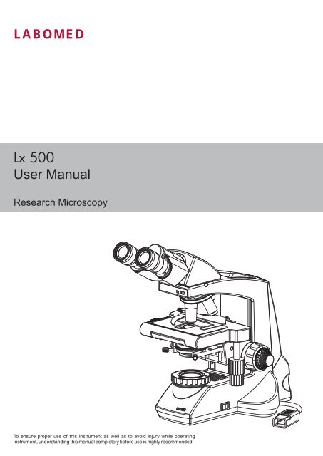
<strong>LABOMED</strong><strong>Lx</strong> <strong>500</strong>User <strong>Manual</strong>Research MicroscopyTo ensure proper use of this instrument as well as to avoid injury while operatinginstrument, understanding this manual completely before use is highly recommended.
CONTENTS1 INTRODUCTION 12 SAFETY INFORMATION 2-43 <strong>Lx</strong> <strong>500</strong> BINOCULAR 54 <strong>Lx</strong> <strong>500</strong> TRINOCULAR 65 <strong>Lx</strong> <strong>500</strong> ERGONOMIC 76 STANDARD COMPONENTS 87 OPTIONAL ACCESSORIES 9-108 INITIAL SETUP 119 ASSEMBLY 1210 SUMMARY OF BRIGHTFIELD OBSERVATION PROCEDURE 1311 DETAILED OBSERVATION PROCEDURE 14-1812 TROUBLESHOOTING GUIDE 19-2013 SPECIFICATIONS 21
1INTRODUCTIONThe <strong>Lx</strong> <strong>500</strong> is a research microscope reflecting a modern design as well as the latest in optical and mechanicaladvancements. Designed for professionals as well as clinicians, this microscope offers many features and functions for adiverse set of applications. Here are a few points highlighting the benefits of the <strong>Lx</strong><strong>500</strong>:- Extra clarity and contrast is provided through a 360° rotatable Binocular body inclined at 30° with IPD adjustments.- The pressure die cast stand consists of ball bearing, friction based focusing mechanism to avoid any loss in motion.- The sturdy new stylish design provides a high degree of comfort as well as stability.- The high powered objectives are spring loaded to prevent accidental damage to specimen slides.- The reverse angle quadruple nosepiece has a comfortable ribbed grip for easy rotation that also safeguards the turretsystem against any damage. All positions are par-centered and par-focalised ensuring the highest level of accuracy.- The ball bearing mechanical stage allows smooth travel over a 76 x 50mm area with spring loaded stage clamps for retainingthe specimen at the exact position desired. A 0.1mm vernier scale provides accurate location of specimen area.- High power illumination is delivered through our well crafted Universal Power Supply operatable within range of 100V- 240VAC input. This ensures continuous operation even under fluctuating voltages.- Our Halogen bulb (6V-30W) has an average life span of up to <strong>500</strong> hours.- The <strong>Lx</strong> <strong>500</strong> comes equipped with a removable flip top N.A. 1.25 Abbe condenser with aspheric lens for brighter illuminationlevels, and an iris diaphragm for better resolution and contrast control.1
2 SAFETY INFORMATION<strong>Lx</strong> <strong>500</strong>1. After the microscope has been used for observation of a specimencontaining bacteria, clean all parts coming in contact with the specimento prevent infection.Be sure to remove the specimen before moving this product.In case the specimen is damaged by erroneous operation, it is importantto clean all surfaces that may have come in contact with the specimen.Fig. 1Applicable bulb 6V30W Halogen bulb P/N EL-4553. Install microscope on a sturdy, level table or bench and avoid any restriction of air vents in the base of the unit.Do not place microscope on a flexible surface, as this could result in blocking the air vents and cause overheating.4. Always use the power cord provided by <strong>LABOMED</strong>. If the proper power cord is not used, product safetyperformance cannot be warranted.5. When installing the microscope, route the power cord away from the microscope frame. Should the power cordcome in contact with the microscopes base, the power cord could melt due to overexposure to heat.6. Always ensure that the grounding terminal of the microscope and that of the wall outlet are properly connected. Ifthe unit is not grounded, <strong>LABOMED</strong> can not warrant electrical safety.7. Never allow metallic objects to penetrate the air vents of the microscope frame as this could result in user injury anddamage to the microscope.8. After operation of microscope, be sure to disconnect power cord from connector socket of the microscope or fromthe wall power outlet.Safety SymbolsThe following symbols are found on the microscope. For optimal use, it is recommended that users understandthese symbols and always use the equipment as prescribed.Symbol!ExplanationThis surface has a tendency to heat up and should not be touched unlesssystem has completely cooled down.Before use, carefully read the instruction manual. Improper use could result ininjury to the user and/or damage to the equipment.Warning against risk of electric shock.|Main switch is ON.Main switch is OFF.2
!CautionIf the microscope is used in a manner not specified by this manual, the safety of the user may not be warranted. Inaddition, the equipment may also suffer damage. Always use the equipments as outlined in this instruction manual.1Getting StartedFig. 21. A microscope is a precision instrument with delicate glass components.Please handle with care.2. Do not use the microscope where it is subjected to direct sunlight, hightemperature, humidity, dust and vibrations. (For the operatingconditions, see chapter 14, "SPECIFICATIONS")3. The microscope is ventilated by natural convection. Be sure to leaveenough space (10 cm or more) around body when installing the unit.4. Arm handle is provided for carrying the microscope.! To prevent damage, do not hold the microscope by the stage orobservation tube.Be sure to remove the specimen from the stage clip whiletransporting unit to avoid damage to the specimen slide.2Maintenance and Storage1. Clean all glass components by wiping gently with cleaning cloth provided. To remove fingerprints or oil smudges,wipe with cleaning cloth slightly moistened with a mixture of petroleum (85%) and isopropanol (15%).! Since solvents such as petroleum and isopropanol are highly flammable, they must be handled carefully.Be sure to keep these chemicals away from open flames or potential sources of electrical sparks - forexample, electrical equipment that is being switched “ON” or “OFF”. Also remember to always use thesechemicals only in a well and ventilated room.2. Do not attempt to use organic solvents to clean the microscope components other than the glass components. Toclean non-glass components, use a lint-free, soft cloth slightly moistened with a diluted neutral detergent.3. Do not disassemble any part of the microscope as this could result inmalfunction or mitigated performance.4. When not using the microscope, ensure that the frame is fully cooledbefore storing the unit in a dry locker or covering with a dust cover(provided).5. To clean the condenser, fully loosen the securing knobs and remove thecondenser by lowering condenser bracket then, wipe the front lens ofthe condenser with optical cleaning solution (mixture suggested above)and lens tissue.The condenser can be re-attached by replacing the condenser in itsseat, tightening securing screws, and raising condenser bracket todesired position.Fig. 33
<strong>Lx</strong> <strong>500</strong>4 Care & MaintenanceYour microscope has been engineered for a long and safe operational life with the least amount of maintenancerequired. In general, routine maintenance is limited to keeping the microscopes working parts lubricated and opticsclean. Always cover the microscope with the provided dust cover when not in use.Optical Cleaning:1. The objectives have been adjusted for a tight fit to prevent any damage during transportation. To remove anobjective, rotate it counterclockwise while gripping it with a rubber sheet, etc. to avoid any slippage.2. To clean the lens surfaces, remove dust using a soft brush or compressed air (cans available at your localelectronics store). For removing finger marks or grease, soft cleaning cloth or lens tissue lightly moistened withcleaning solution (85% petroleum ether and 15% isopropanol) should be used. For cleaning the objective optics,use Methanol. Observe sufficient caution in handling Methanol. Place the objectives and/or eyepieces on a dustfreesurface (e.g. aluminum foil). All other optical components to be cleaned should be as accessible as possible.3.. Blow all loose dust particles away with compressed air or mini dust blower.4. Remove all water-soluble dirt with distilled water. If this is unsuccessful repeat using a solution of diluted handsoap liquid. Remove any remaining residue with a dry cotton swab.5. To remove oil, use a solution of diluted hand-soap liquid initially. If this does not produce a satisfactory result,repeat the cleaning using a solvent (Optical Cleaning Solution 85% petroleum ether and 15% isopropanol).6. Grease must always be removed using a solvent.7. Cleaning is achieved by using a spiral motion from the center to the rim. Never wipe using zig-zag movements asthis will only spread the dirt. With larger optical surfaces (e.g. tube lenses) the spiral motion starts initially at the rimbefore moving to the middle and is then followed by a center to rim cleaning motion. Normally several spiral wipesare recommended.We recommend pure, volatile petroleum ether or Optical Cleaning Solution as explained in point 3 above.zig-zag motion (X) spiral motion ( )Wipe using a spiral movement. Do not use a zig-zag motion!2. Cleaning of painted surfaces :Avoid the use of any organic solvent ( e.g. thinner, xylene, ether, alcohol etc.) for cleaning of painted surfaces ofthe instrument. Painted surfaces can be cleaned with a very lightly moistened micro fiber cloth. Loose dust andother dirt particles can be removed using a soft bristle brush used exclusively for this purpose.4
3 <strong>Lx</strong> <strong>500</strong> Binocular<strong>Lx</strong> <strong>500</strong>EyepiecesBinocular viewing tube, 30° inclinedObservation tubeclamping screwRevolving nosepieceObjectivesSpecimen holderMechanicalstageAperture irisdiaphragm ringAbbe condensorFilter holderCoarse andfine focus knobX-Y movement control knob5
4<strong>Lx</strong> <strong>500</strong> Trinocular<strong>Lx</strong> <strong>500</strong>Trinocular PortEyepiecesTrinocular viewing tube, 30° inclinedObservation tubeclamping screwRevolving nosepieceObjectivesSpecimen holderAperture irisdiaphragm ringAbbe condensorFilter holderMechanicalstageCoarse andfine focus knobX-Y movement control knob6
5<strong>Lx</strong> <strong>500</strong> Ergonomic Binocular<strong>Lx</strong> <strong>500</strong>EyepiecesErgonomic Binocular viewing tube,0° to 25° inclinedObservation tubeclamping screwRevolving nosepieceObjectivesSpecimen holderMechanicalstageAperture irisdiaphragm ringAbbe condensorFilter holderCoarse andfine focus knobX-Y movement control knob7
6STANDARD COMPONENTS<strong>Lx</strong> <strong>500</strong>After removing your microscope from its packaging, make sure that all of the following contents are present.“Please note that the contents of your microscope may vary as the optional configuration, contrasting method orviewing body opted for may not be of the standard configuration highlighted here”EyepiecesBinocular viewing tube, 30° inclinedObservation tubeclamping screwRevolving nosepieceObjectivesSpecimen holderMechanicalstageAperture irisdiaphragm ringAbbe condensorFilter holderCoarse andfine focus knobDaylight (blue) filterPaired EyepiecesAllen Wrench 3mmPower Cord8
7OPTIONAL ACCESSORIESSystem Diagram of Optional AccessoriesVideo adapter1/2"&1/3"Digital camera adapteriVu 1<strong>500</strong> iVu 3000 iVu <strong>500</strong>0 iVu 7000Binocular headTrinocular headErgonomic headWF 10xWF 16xWF 20xRP 4x RP 10x RP 20x RP 40x (SL) RP 50x (SL, Oil) RP 100x (SL, Oil) RP PH 10x RP PH 20x RP PH 40x (SL) RP PH 100x (SL, Oil)RP FL 4x RP FL 10x RP FL 20x RP FL 40x (SL) RP FL 50x (SL, Oil) RP FL 100x (SL, Oil) RP 100x,(Oil, Iris)Flip top condenserPolarizer MountAnalyzer MountBlue filterGreen filterHalogen bulbInstallation and Operation of Optional Accessories1 iVu Camera Module System1.Mount the Video adapter 1/2” (part # 3143300-912) on Trinocularobservation head.2. Mount iVu Camera Module System on video adapter.9Fig. 4
<strong>Lx</strong> <strong>500</strong>2Optional Eyepieces10X eyepieces are provided. To replace:1. Pull out the 10x eyepieces out from the observation heads ocular tube.2. Insert desired eyepieces in empty ocular tube.3Phase TurretFig. 512Fig. 61. Remove the condenser from its position by loosening the two thumbscrews (1) on both sides of the condenser as shown in figure 6.2. Place the phase annulus turret in position from where the condenserhas been removed.3. The long “push in to engage” thumbscrews (2) on both sides of thephase turret are provided for proper alignment of the phase ring. Bydisengaging these screws, the phase turret can be adjusted at anydesired phase annulus (10x, 20x, 40x & 100x) by turning thethumbwheel to the desired position. There is also an ‘0’ setting on thethumbwheel for bright field applicationNote: Refer to the user manual provided with the Phase Contrastkit for centering and alignment.10
8INITIAL SETUP1ObjectivesObjectives are factory set. Objectives are par-centered and parfocalisedduring assembly.All objectives have been secured for a tight fit to prevent them fromcoming loose during transit. To remove an objective, rotate itcounterclockwise while holding it with a rubber grip to avoid anyslippage.Fig. 72Observation Head1Install the observation head using the following procedure:1. Using allen wrench 3mm (provided), loosen the Head LockingScrew (1) and remove the dust cover cap provided in dovetailcavity as well as on observation head dovetail.2. Mount the Observation Head by engaging the dovetail providedat the bottom of the head into the dovetail cavity provided in themicroscopes arm.3. Tighten the Head Locking Screw (1) after positioning theObservation Head as desired. See figure 8.Fig. 83EyepiecesInsert the eyepieces into the ocular tube of Observation Head usingfollowing procedure:1. Remove the protective caps from the observation tube.2. Insert 10x eyepieces into the spring loaded and to preventundesired rotation of eye pieces. See figure 9.Fig.911
9ASSEMBLY<strong>Lx</strong> <strong>500</strong>Each standard set can be assembled by simply attaching the bulb, filter and power cord.1Installing or Replacing the Lamp BulbFig. 10Before attaching the lamp bulb, remove the parts that may drop such as thefilter and specimen from the microscope frame, and place the microscopeon its back so that the bottom plate is exposed.1. Pull out the lamp house cover (1) to detach it.2. Pull up the lamp from the lamp holder & replace with lamp.3. Replace the lamp house cover.Always use the designated bulb. Using a bulb other than thosespecified by <strong>LABOMED</strong> may lead to a fire hazard and decentering oflight. Fingerprints or stains on the lamp bulb reduce its life. Ifcontamination occurs, wipe bulb surface with a cloth slightlymoistened with alcohol.! Caution: For Bulb Replacement During Use or Right After UseThe bulb, lamp socket and areas near these will be extremely hot during and right after use. Set the mainswitch to" O" (OFF), disconnect the power cord from the wall outlet, and allow the bulb and lamp socket tocool before replacing the bulb with a new bulb of the designated type. Cooling time may vary to usersdiscretion.2Mounting the Daylight (Blue) Filter21This filter modifies the color of observation light into a natural (daylightcolor).• Fit the filter (1) into the bottom of the condenser (2) until it clicks intoplace. (Figure 11).Fig. 1112
10SUMMARY OF BRIGHTFIELD OBSERVATION PROCEDUREFlip the main switch to “ON”Place the specimen on the stage.On/OffEngage the 10X objective in the light path.A/C InletBring the specimen in focus.Adjust the observation tube and eyepiecesAdjust the interpupillary distance.Adjust the dioptric setting.Adjust the aperture iris diaphragm.Engage the objective to be used in the lightpath and bring the specimen in focus.Engage the required filters.Adjust the brightness.Observe Specimen.13
11DETAILED OBSERVATION PROCEDURE<strong>Lx</strong> <strong>500</strong>1Turning the Lamp ON1. Flip the main switch to ” I ” (ON) as shown in Figure 12.2. Rotating the light intensity adjustment knob (Fig. 13) in the directionof the arrow increases brightness and rotating knob in the oppositedirection decreases brightness. The intensity bar next to the knobindicates the direction of intensity level.1Fig. 122Fig. 132Placing specimen on the stage31Fig. 144521. Rotate the coarse adjustment knob (2) in anticlockwise direction to fullylower the stage.2. Open the bow-shaped lever (3) outward by pulling on lever handle (1),place the specimen by sliding the specimen glass plate(s) on the stagefrom the front toward the slide seat at the rear.3. After positioning your specimen slides,(2 max) return the bow-shapedlever (3) gently by slowly releasing control knob (1).4. Rotating the upper co-axial knob controlling the Y-axis movement (4)moves the specimen in the vertical direction. Rotating the lower knob(5) moves the specimen in the X- axis or horizontal direction.! Do not adjust the specimen holder directly by hand. This willdamage the rotary mechanisms.! When the specimen holder reaches stop position, the rotationforce of the X/Y knobs become stiff. Stop rotating the at this point.14
Cover glassCover glassThis is the glass plate placed on the specimen. For optimum opticalperformance, the cover glass thickness, which is the distance from itssurface to the specimen surface, should be 0.17 mm.Slide glassFig. 15Slide glassThis glass plate should ideally have a length of 76 mm, width of 26 mm±1 mm and thickness between 0.9 and 1.4 mm.“Vernier Scales”21These scales allow for easy identification of the specimen’s position(coordinates), making it easy to return to a particular region of interestafter scanning the slide. (Figure 16.)1. The horizontal coordinate can be read at position (1) on the specimenholder.2. The vertical coordinate can be read at the index line (2).Fig. 163 Adjusting the FocusFocusing ProcedureWD3121. Rotate the coarse adjustment knob (1) clockwise so that the objective(3) is as close as possible to the specimen (We recommend starting with10X).2. While observing the specimen through the eyepieces, slowly rotate thecoarse adjustment knob (1) counterclockwise to lower the stage.3. When coarse focusing of the specimen is obtained (a blurr image isobserved), rotate the fine adjustment knob (2) for fine detail focusing inanticlockwise direction.Fig. 17Working Distance (WD)The WD refers to the distance between each objective and the specimen,ObjectiveMagnification4X 10X 40X 100XWD (mm) 30.5 4.82 0.55 0.1115
<strong>Lx</strong> <strong>500</strong>4Adjusting the Interpupillary Distance (IPD)The inter-pupillary distance adjustment consists of moving the twoeyepieces to align with both eyes’ pupils so that you can observe asingle microscopic image through two eyepieces in stereo vision. Thisgreatly helps to reduce fatigue and discomfort during observation.While looking through the eyepieces, move both eyepieceslaterally until the left and right fields of view coincide completely. Theposition of index dot (•) indicates the inter-pupiliary distance value.Fig. 18Note your interpupillary distance so that it can be quickly referred to inthe future. This may need when multiple users work with themicroscope.5Adjusting the DiopterProcedure for adjusting the diopter:1. Rotate the right eyepiece to match the markings of your IPD (If yourIPD is 64, rotate the eyepiece to 64 mark).2. While looking through the right eyepiece with your right eye, rotatethe coarse and fine adjustment knobs to bring the specimen intofocus.3. While looking through the left eyepiece with your left eye, rotate onlydiopter adjustment ring on the eyepiece until specimen is at its bestpossible focus.Fig. 19Using the Eye GuardsWhen Wearing EyeglassesUse with the eye guards in the normal, folded-down position. This willprevent the eyeglasses from being scratched.Fig. 20When Not Wearing EyeglassesExtend the folded eye guards outwards (direction of the arrow) toprevent ambient light from entering into your line of vision.16
6 Centering the CondenserThere is a possibility of having the condenser de-centered during shipping.it is mandatory to check the centering before observing the specimen as itis required to distribute even light to the specimen.Fig. 21For models with Koehler illumination:1. Bring the 10x objective (1) in the front position.2. Move the condenser to the highest point.3. Close the koehler. (2) Focus the light spot as show in the illustrationbelow.4. Use the centering screws (3) provided on left and right sides of thecondenser bracket to bring the light spot to center of the view field.6Adjusting the Condenser Position and Aperture Iris DiaphragmThe condenser is most often used in the highest position. If the observedfield of view is not bright enough, brightness may be improved by loweringthe condenser slightly211. Rotate the condenser height adjustment knob (2) to move thecondenser to the highest or desired position.2. The aperture iris diaphragm ring (1) has an objective magnification scale(4X, 10X, 40X, 100X). Rotate the ring so that the magnification of theobjective is clearly visible while using the microscope.Fig. 227Switching the Objectives1Rotate the revolving nosepiece (1) so that the objective to be used is in lineabove the specimen. Always use the ribbed grip(1) to rotate the objectivenosepiece.17Fig. 23
<strong>Lx</strong> <strong>500</strong>8 Using the 100X Immersion ObjectiveThe designated immersion oil should be in contact with the cover lens ofthe 100X immersion objective. If not, the specimen will appear distortedand dull. It is recommended that <strong>LABOMED</strong> immersion oil is always used.Immersion Process:1. Bring the specimen in focus using first the 10x, then 40x objective.2. Disengage the 40x cycling towards 100x, and place a drop of immersionoil on the center point of the specimen.Fig. 243. Rotate the revolving nosepiece to engage the immersion objective androtate the fine adjustment knob to bring the specimen into focus(Since air bubbles in the oil will affect the image quality, make surethat the oil Is free of bubbles. To remove bubbles, rotate the revolvingnosepiece slightly to agitate the oil).4. The condenser of this microscope manifests the full performance whenoil is placed between the slide glass and the front lens of condenser. If oilis not placed there, the observed image may appear dark.5. After use, remove oil from the objective front lens by wiping with lenstissue slightly moistened with an ether (70%) alcohol (30%) mixture.CautionIf immersion oil makes contact with your eyes, rinse eyes outthoroughly with fresh water. If immersion oil makes contact withskin, wash affected areas with soap and water.If prolonged discomfort is experienced, consult your physicianimmediately.18
12 TROUBLESHOOTING GUIDEUnder certain conditions, performance of the unit may be adversely affected by factors other than defects. If problems occur,please review the following list and take corrective action as needed. If problem persists, please contact <strong>LABOMED</strong> or yourlocal <strong>LABOMED</strong> dealer.Observation Cause Remedy1. Uneven brightness in observation The objective is not engaged in the Engage the objective into positionfield light path until the nose turret clicksThe condenser is too lowThe objective, eyepiece, condenserand/or window lens are dirtyRaise up to achieve more light (Pg#18)Clean them thoroughly as previouslyprescribed in “Optical Cleaning”(pg#4)2. Dust or stains are visible in The eyepiece, condenser, window lens Clean glass parts thoroughly with lensobservation field and/or specimen glass is dirty tissue and cleaning solutionprescribed in“Optical Cleaning”(Pg#4)3. Glare visible in field of View The condenser is too low Raise condenser lightThe condenser iris diaphragm ring is Adjust the aperture according to theclosed objective magnification (Pg# 18)4. Observation image is hazy The objective is not engaged in the Engage the objective into positionor unclear light path until it clicks (Pg# 18)The objective, eyepiece, condenserand/or specimen glass is dirtyClean glass parts thoroughly with lenstissue and cleaning clothImmersion oil is not used with an Use immersion oil asimmersion objective. suggested (Pg# 19)Bubbles are present in immersion oilThe specified immersion oil is not usedRemove the bubbles by agitation(Pg# 19)Use the immersion oil supplied by<strong>LABOMED</strong>5. Part of image is defocused The objective is not properly engaged Engage the objective into positionin the light pathuntil the nose turret clicksThe specimen is not set properly onthe stageSet the specimen correctly on thestage and secure using the specimenholder (Pg# 15)6. Coarse focus adjustment cannot The condenser is too low Raise the condenserlower the stage low enough7. Fields of view through both The interpupillary distance is not Adjust IPD to the appropriate settingeyepieces is inconsistent adjusted properly (Pg# 17)Dioptric compensation for the two eyes Adjust diopter settings (Pg# 17)is not setThe left and right eyepieces are ofdifferent magnificationEnsure that both eyepieces are ofsame magnification. <strong>LABOMED</strong>does not recommend using third partyeyepieces in conjunction with<strong>LABOMED</strong> microscopes.19
<strong>Lx</strong> <strong>500</strong>Observation Cause Remedy12. Objective hits the specimen when The specimen slide is upside down Set the specimen correctly with thean objective is switched to a highercover glass facing upwardsmagnification objectiveThe cover glass is too thickUse a cover glass with thickness of0.17mmThe stage is raised too highThe slide has slipped from the slideholderLower the stageRe-position the slide in the slideholderSlide is of excessive thickness Use slides with thickness between 0.9and 1.4mm13. Bulb does not turn On Bulb is not mounted Attach a bulbBulb is blownReplace the bulbThe power cord is unplugged / Not firmly Ensure power cord is securilly pluggedsecuredinto the box socket + wall outletFuse is blownBattery is lowCheck and replace with live fuseCharge battery14. Bulb blows easily The specified bulb is not used Replace with the specified bulb20
13 SPECIFICATIONS1. Illumination Built-in illumination system Halogen2. Focusing mechanism Stage height adjustment mechanismFine adjustment scale: 0.003µm per graduationFine adjustment stroke: 0.3mm per turnTotal stroke: 12.7mmCo-axial coarse and fine focusing on ball drive3. Revolving nosepiece Quintuple positions fixed (Reverse angle)4. Observation tube Binocular Trinocular ErgonomicField number 22 (Standard) 22 (Standard) 22 (standard)Tube tilting angle 30° 30° 0°-25°Interpupillary distance 48-75 48-75 48-75adjustment range5. Stage Size 200 x 160mm (with mechanical stage)Movement rangeSpecimen holder76 x 50mmDouble specimen6. Condenser Type Fliptop Abbe condenser (daylight filter detachable)N. A. 1.25Aperture iris diaphragmBuilt-in7. Dimensions & Weight 301.0mm (L) x 227.0mm (W) x 420.mm (H); 9 kg net8. Electrical Halogen 6V-30WBulb lifeUpto <strong>500</strong> hours9. Operating environment Indoor useAltitude: Max. 2000 metersAmbient temperature: 5° to 40°C (41° to 104° F)Maximum relative humidity: 80% for temperature up to 31°C (88°F),decreasing linearly through 70% at 34°C (93°F),to 50% relative humidity at 40°C(104°F)Supply voltage fluctuations: Not to exceed ±10% of the normal voltage.Pollution degree: 2 (in accordance with IEC60664)Installation/Overvoltage category: II (in accordance with IEC60664)21
www.laboamerica.comOur policy is one of continuous development. Labo America, Inc., reserves the right to change design and specifications without prior notice.Labo America Inc.920 Auburn CourtFremontCA 94538U.S.A.Telephone: 510 445 1257Fax: 510 445 1317sales@laboamerica.com<strong>LABOMED</strong> and <strong>Lx</strong> <strong>500</strong> are registered trademarks of Labo America, Inc.With a policy of continuous development, Labo America, Inc. reserves the right to change design and specifications without prior notice.© 2009 Labo America, Inc. | 9144000-990A 02-2009