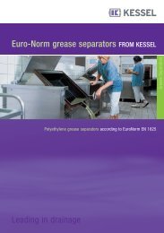
KESSEL Grease separator âMâ NG 2, 4, 7 and 10 For installation in ...
KESSEL Grease separator âMâ NG 2, 4, 7 and 10 For installation in ...
KESSEL Grease separator âMâ NG 2, 4, 7 and 10 For installation in ...

Create successful ePaper yourself
Turn your PDF publications into a flip-book with our unique Google optimized e-Paper software.
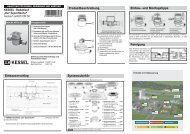
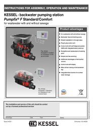
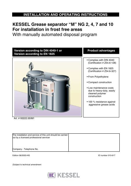
INSTALLATION AND OPERATI<strong>NG</strong> INSTRUCTIONS<strong>KESSEL</strong> <strong>Grease</strong> <strong>separator</strong> “M” <strong>NG</strong> 2, 4, 7 <strong>and</strong> <strong>10</strong><strong>For</strong> <strong><strong>in</strong>stallation</strong> <strong>in</strong> frost free areasWith manually automated disposal programVersion accord<strong>in</strong>g to DIN 4040-1 orVersion accord<strong>in</strong>g to EN 1825Product advantagesprodotto Complies with DIN 4040(Certification # Z54.6-128) Complies with EN 1825(Certification # Z54.6-327) From Polyethylene Compact construction Low ma<strong>in</strong>tenance costsdue to heavy-duty, easilycleaned polymerconstruction <strong>10</strong>0 % resistance aga<strong>in</strong>staggressive grease acidsArt. # 93222.00/M1The <strong><strong>in</strong>stallation</strong> <strong>and</strong> service of this unit should be carriedout by a licensed professional servicerCompany - Telephone No.Edition 06/2003-HG ID number 0<strong>10</strong>-617(Subject to technical amendment
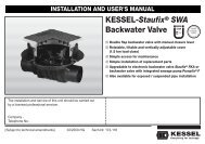
Safety precautionsDear Customer,Before the <strong>KESSEL</strong> Euro Separator Version G is <strong>in</strong>stalled <strong>and</strong> placed <strong>in</strong> operation pleasecarefully read <strong>and</strong> follow all of the <strong>in</strong>structions conta<strong>in</strong>ed <strong>in</strong> this Installation, Ma<strong>in</strong>tenance<strong>and</strong> User’s Manual.Upon delivery of the Euro Separator please thoroughly <strong>in</strong>spect the <strong>separator</strong> to make surethat it has not been damaged dur<strong>in</strong>g shipp<strong>in</strong>g. In case damage has occurred to the<strong>separator</strong>, please follow the <strong>in</strong>structions listed <strong>in</strong> the ‚Guarantee‘ section of this user’smanual.By <strong><strong>in</strong>stallation</strong>, use, ma<strong>in</strong>tenance <strong>and</strong> repair of this unit please follow all appropriateDIN / VDE / DVGW safety precautions <strong>and</strong> accident prevention guidel<strong>in</strong>es. Also please follow anylocal safety precautions <strong>and</strong> accident prevention guidel<strong>in</strong>es established <strong>in</strong> your area.Please note that the unit is designed to receive kitchen waste water with a maximum temperatureof 60 degrees Celsius (140 degrees F). Temperatures higher than 60 degrees Celsius coulddamage the unit._______________________________________________________________________Do not st<strong>and</strong> or place excessive weight on the <strong>separator</strong>. Dur<strong>in</strong>g disposal / empty<strong>in</strong>g of aType G <strong>separator</strong>, a step ladder should be used to help ga<strong>in</strong> access to the open<strong>in</strong>gs on the top ofthe <strong>separator</strong>.NO SMOKI<strong>NG</strong>! Smok<strong>in</strong>g must not be permitted near the <strong>separator</strong> dur<strong>in</strong>g use, ma<strong>in</strong>tenance <strong>and</strong>repair of the unit due to the potential build up of methane / biogas.SLIPPERY WHEN WET! Take caution when st<strong>and</strong><strong>in</strong>g / walk<strong>in</strong>g near the <strong>separator</strong>.Dur<strong>in</strong>g disposal, clean<strong>in</strong>g <strong>and</strong> ma<strong>in</strong>tenance the surround<strong>in</strong>g area can become extremely slipperydue to spilled water / grease / fat.Separator Area Regulations: No access of the <strong>separator</strong> for unauthorized personnel No storage of food / groceries / provisions (for hygienic reasons) if the <strong>separator</strong> is <strong>in</strong>stalledunderground with<strong>in</strong> a build<strong>in</strong>g. The location of the <strong>separator</strong> should be chosen carefully as to allow sufficient access forma<strong>in</strong>tenance, <strong>in</strong>spection, repair <strong>and</strong> disposal of the <strong>separator</strong>. The wastewater <strong>in</strong> a grease <strong>separator</strong> can conta<strong>in</strong> bacteria. After com<strong>in</strong>g <strong>in</strong> contact withwastewater or the <strong>separator</strong> itself, it is important to wash, clean <strong>and</strong> dis<strong>in</strong>fect all sk<strong>in</strong> which hasbeen contam<strong>in</strong>ated.All personnel hav<strong>in</strong>g anyth<strong>in</strong>g to do with the <strong>separator</strong> should have a sound knowledgeof the above safety precautions.2
2. Installation2.3 Electrical InstallationsAll electrical connections <strong>and</strong> work should be h<strong>and</strong>led by a professional, licensed electrician.1. Fuse: for 2.6 kW pump – 16 AMP2. Fuse: for 4.0 kW pump – 20 AMP3. When connect<strong>in</strong>g the pump be sure that the cables are connected properly so that the pump'simpeller rotates <strong>in</strong> the correct direction (see directional stickers on both pumps).4. The run-dry motor protection sett<strong>in</strong>g is to be checked by do<strong>in</strong>g the follow<strong>in</strong>g:Please take care that: That the user's manual <strong>and</strong> all operat<strong>in</strong>g <strong>in</strong>structions concern<strong>in</strong>g the <strong>separator</strong> are kept <strong>in</strong> a safelocation nearby the <strong>separator</strong>. That the disposal procedure is conducted exactly as it is described <strong>in</strong> the user's manual. All relevant safety precautions are followed at all times. Only allow professional licensed disposal companies to h<strong>and</strong>le the disposal of the <strong>separator</strong>. Right reserved for technical changes.2.4 Installation example1. <strong>Grease</strong> <strong>separator</strong>e M <strong>NG</strong> 4<strong>KESSEL</strong>2. Storz-B hook up connection3. Sampl<strong>in</strong>g device4. Refill<strong>in</strong>g device5. Shut-off valve6. Water connectiona cold water connectionb warm water conneciotn7. Dispoal pipe8. Non-return valve9. Eletrical connection<strong>10</strong>. <strong>KESSEL</strong> Basement dra<strong>in</strong>“The universal” with backwatervalve11. <strong>KESSEL</strong> lift<strong>in</strong>g stationEntlüftung über Dach = Ventilation pipeAnschluss für Entsorgungswagen = Connection for disposal truckGehsteig = SidewalkKanalanschluss = Connection to public sewer6
2.5 Dimensioned draw<strong>in</strong>g2.5.1 <strong>Grease</strong> <strong>separator</strong> acc. to DIN 40402. Installation1. Inlet2. Outlet3. Sludge trap4. <strong>Grease</strong> trap5. Quick-release covers6. Inspection w<strong>in</strong>dow7. Solenoid valve8. Leva manuale9. Clean<strong>in</strong>g jets<strong>10</strong>. Clean<strong>in</strong>g water stream11. Pump with closure locks12. Warm water connection(r<strong>in</strong>s<strong>in</strong>g) <strong>and</strong> cold waterconnection (refill<strong>in</strong>g withfresh water)13. Control unit14. Disposal pipe<strong>NG</strong>(l/sec)DNDimension w/opump a x ba bb1 h h1 h2 h3Separator volumesWeightapproxSludgechamberSeparator2 <strong>10</strong>0 1700 680 <strong>10</strong>80 1455 <strong>10</strong>30 1<strong>10</strong>0 1180 220 l 570 l 240 kg4 <strong>10</strong>0 2250 920 1320 1455 <strong>10</strong>30 1<strong>10</strong>0 1180 430 l <strong>10</strong>70 l 290 kg7 150 3180 1150 1550 1455 <strong>10</strong>30 1<strong>10</strong>0 1180 720 l 1870 l 400 kg<strong>10</strong> 150 3600 1350 1750 1455 <strong>10</strong>30 1<strong>10</strong>0 1180 <strong>10</strong>52 l 2480 l 440 kg2.5.2 <strong>Grease</strong> <strong>separator</strong> acc. to EN 1825<strong>NG</strong> DN OD a b b1 h1 h2 h3 l Separator volumes <strong>Grease</strong>(l/sec)Sludge Separator storagechamber2 <strong>10</strong>0 1<strong>10</strong> 940 650 950 930 <strong>10</strong>00 13<strong>10</strong> 1250 200 l 212 l <strong>10</strong>6 l4 <strong>10</strong>0 1<strong>10</strong> 1500 650 950 930 <strong>10</strong>00 13<strong>10</strong> 18<strong>10</strong> 400 l 354 l 177 l7 150 160 1600 920 1220 1130 1200 1560 1850 700 l 567 l 302 l<strong>10</strong> 150 160 2430 920 1220 1130 1200 1560 2700 <strong>10</strong>00 l 794 l 423 l7
5. Disposal for grease <strong>separator</strong> acc. to. DIN 40405.1 <strong>For</strong> <strong>separator</strong>s with manually automated disposalSeparators <strong>NG</strong> 2, <strong>NG</strong> 4, <strong>NG</strong> 7 <strong>and</strong> <strong>NG</strong> <strong>10</strong> acc. to DIN 4040Program Function Valve sett<strong>in</strong>gPump runn<strong>in</strong>g time <strong>in</strong> secondsstep<strong>NG</strong> 2 <strong>NG</strong> 4 <strong>NG</strong> 7 <strong>NG</strong> <strong>10</strong>1 partial “Leeren” / empty 40 60 80 120empty2 mix “Mischen” / mix 120 180 200 3603 empty “Leeren” / empty 120 180 300 3604 fill “Mischen” / mix <strong>10</strong>0 <strong>10</strong>0 140 2005 mix “Mischen” / mix 120 120 160 2406 empty “Leeren” / empty 30 30 60 607 fill “Spülen” / r<strong>in</strong>se <strong>10</strong>0 <strong>10</strong>0 140 2008 r<strong>in</strong>se “Spülen” / r<strong>in</strong>se 60 90 <strong>10</strong>0 1809 empty “Leeren” / empty 30 30 60 60<strong>10</strong> fill “Spülen” / r<strong>in</strong>se 60 <strong>10</strong>0 140 20011 r<strong>in</strong>se “Spülen” / r<strong>in</strong>se 60 90 <strong>10</strong>0 18012 empty “Leeren” / empty 30 30 60 6013 fill “Leeren” / empty 300 420 500 <strong>10</strong>00Pump Valve warm Valve cold waterH<strong>in</strong>twateron off off Let the pump run until waterlevel has dropped by approx.30 cmon off offon off off until the pump runs dryoff on off approx. 25 cm fill<strong>in</strong>g levelon off offon off off until the pump runs dryoff on off approx. 25 cm fill<strong>in</strong>g levelon off offon off off until the pump runs dryoff on off approx. 25 cm fill<strong>in</strong>g levelon off offon on off until the pump runs dryoff off on upntil <strong>separator</strong> overflow levelTime sett<strong>in</strong>gs can also be customized depend<strong>in</strong>g on pump<strong>in</strong>g height, temperature or waterpressures. Flow rate through a DN 25 solenoid valve is 23 m3/hour.9
5. Disposal for grease <strong>separator</strong> acc. to. EN 18255.2 <strong>For</strong> <strong>separator</strong>s with manually automated disposalSeparators <strong>NG</strong> 2, <strong>NG</strong> 4, <strong>NG</strong> 7 <strong>and</strong> <strong>NG</strong> <strong>10</strong> acc. to EN 1825Program Function Valve sett<strong>in</strong>g Pump runn<strong>in</strong>g time <strong>in</strong> secondsstep<strong>NG</strong> 2 <strong>NG</strong> 4 <strong>NG</strong> 7 <strong>NG</strong> <strong>10</strong>1 partial “Leeren” / empty 30 40 50 80empty2 mix “Spülen” / r<strong>in</strong>se 120 180 200 3603 empty “Leeren” / empty 90 130 180 2204 fill “Spülen” / r<strong>in</strong>se <strong>10</strong>0 <strong>10</strong>0 140 2005 mix “Spülen” / r<strong>in</strong>se 120 120 160 2406 empty “Leeren” / empty 30 30 60 607 fill “Spülen” / r<strong>in</strong>se <strong>10</strong>0 <strong>10</strong>0 140 2008 r<strong>in</strong>se “Spülen” / r<strong>in</strong>se 60 90 <strong>10</strong>0 1809 empty “Leeren” / empty 30 30 60 60<strong>10</strong> fill “Spülen” / r<strong>in</strong>se 60 <strong>10</strong>0 140 20011 r<strong>in</strong>se “Spülen” / r<strong>in</strong>se 60 90 <strong>10</strong>0 18012 empty “Leeren” / empty 30 30 60 6013 fill “Leeren” / empty 200 260 360 600Pump Valve warm Valve coldH<strong>in</strong>twaterwateron off off Let the pump run until waterlevel has dropped by approx.30 cmon off offon off off until the pump runs dryoff on off approx. 25 cm fill<strong>in</strong>g levelon off offon off off until the pump runs dryoff on off approx. 25 cm fill<strong>in</strong>g levelon off offon off off until the pump runs dryoff on off approx. 25 cm fill<strong>in</strong>g levelon off offon on off until the pump runs dryoff off on until <strong>separator</strong> overflow levelTime sett<strong>in</strong>gs can also be customized depend<strong>in</strong>g on pump<strong>in</strong>g height, temperature or waterpressures. Flow rate through a DN 25 solenoid valve is 23 m3/hour.<strong>10</strong>
6. Ma<strong>in</strong>tenanceMa<strong>in</strong>tenance of the <strong>separator</strong>The <strong>separator</strong> should be tested to make sure that it is completely watertight before it is placed <strong>in</strong>tooperation <strong>and</strong> also dur<strong>in</strong>g periodic <strong>in</strong>tervals thereafter. The macerat<strong>in</strong>g pump as well as the waternozzles are practically ma<strong>in</strong>tenance free.1. Surface care - the <strong>in</strong>terior walls of the <strong>separator</strong> should be cleaned <strong>and</strong> checked forproblems at regular <strong>in</strong>tervals.2. The controls (control unit <strong>and</strong> software) of the <strong>separator</strong> are ma<strong>in</strong>tenance free. Thecapacitive level switch should be checked dur<strong>in</strong>g the bi-annual <strong>in</strong>spection (see electrical<strong><strong>in</strong>stallation</strong>).3. The <strong>separator</strong> should be thoroughly checked two times per year. Dur<strong>in</strong>g these <strong>in</strong>spectionsthe <strong>separator</strong> should be completely emptied <strong>and</strong> thoroughly cleaned. Also, <strong>in</strong>spect to makesure that the <strong>in</strong>terior <strong>and</strong> exterior walls of the sludge separation area <strong>and</strong> the greaseseparation area are <strong>in</strong> operat<strong>in</strong>g condition.,The electrical portions of the <strong>separator</strong> as wellas the pumps should be <strong>in</strong>spected dur<strong>in</strong>g this time.• Before the <strong>separator</strong> is placed <strong>in</strong>to operation <strong>and</strong> at regular <strong>in</strong>tervals thereafter, the <strong>separator</strong>should be checked to make sure that it is water tight.• The <strong>in</strong>terior walls of the <strong>separator</strong>, as well as the exterior walls, should be cleaned <strong>and</strong>checked for damage every time the <strong>separator</strong> contents are disposed.• The <strong>separator</strong> should be <strong>in</strong>spected every 6 months. At this time the <strong>separator</strong> contents shouldbe disposed <strong>and</strong> the entire unit should be cleaned. Dur<strong>in</strong>g the clean<strong>in</strong>g check the sludge trap<strong>and</strong> grease separation portions of the <strong>separator</strong> to make sure they are <strong>in</strong> proper work<strong>in</strong>gcondition.• The electrical systems <strong>and</strong> the <strong>separator</strong>'s pumps should be <strong>in</strong>spected. The run-dry motorprotection sett<strong>in</strong>g is to be checked (see section 3.3 Electrical Installations of Chapter 3 -Installation of this manual.• It is recommended that a written log is kept for the <strong>separator</strong>. Documentation <strong>and</strong> <strong>in</strong>formationconern<strong>in</strong>g all disposals <strong>and</strong> any other work done to the <strong>separator</strong> should be kept <strong>in</strong> this log forfuture reference.Please make sure that:1. This Installation, Service <strong>and</strong> Ma<strong>in</strong>tenance Guide <strong>and</strong> any other documentation relat<strong>in</strong>g tothe <strong>separator</strong> is kept <strong>in</strong> a safe place accessible to all who work on the unit.2. Disposal of the contents of the <strong>separator</strong> follows the exact guidel<strong>in</strong>es stated <strong>in</strong> this guide.3. The disposal of the <strong>separator</strong> is carried out by a qualified, licensed company.11
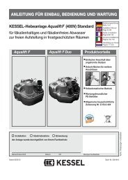
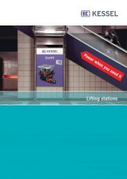
7.1 Sampl<strong>in</strong>g chamber DN <strong>10</strong>0 or DN 1507. Accessories / Replacement parts<strong>KESSEL</strong> offers various sampl<strong>in</strong>g chambers for <strong><strong>in</strong>stallation</strong> <strong>in</strong> frost free rooms or for underground<strong><strong>in</strong>stallation</strong>. Sampl<strong>in</strong>g chambers are odour tight <strong>and</strong> are opened <strong>and</strong> closed by a quick releaselock<strong>in</strong>g clamp. This sampl<strong>in</strong>g chamber makes it possible to take samples of the grease freewastewater for test<strong>in</strong>g (accord<strong>in</strong>g to DIN 38409). Each chamber is equipped with a DN <strong>10</strong>0 <strong>and</strong>DN 150 <strong>in</strong>let <strong>and</strong> outlet. The required sizes can be obta<strong>in</strong>ed by cutt<strong>in</strong>g off the respective section.Type Art. #Horizontal outlet 915 871Vertical outlet 915 8707.2 Lift<strong>in</strong>g stations<strong>KESSEL</strong> offers various lift<strong>in</strong>g stations for <strong><strong>in</strong>stallation</strong> after the <strong>separator</strong> so that the effluent can bepumped up to sewer levels.Output Power Outlet Art. #size1,1 kW 400 V direct (3- DN <strong>10</strong>0 28 659Phase)2,2 kW 400 V direct (3-Phase)DN <strong>10</strong>0 28 631• The <strong>KESSEL</strong> Aqualift ®F for grey or sewageeffluent for frost free areas consists of:• Submersible (IP 68) s<strong>in</strong>gle or double pumps units with s<strong>in</strong>gle vane impellers (40mmmaximum passage) <strong>and</strong> rotation direction <strong>in</strong>dicator <strong>and</strong> 5 meter connection cable• DN <strong>10</strong>0 Outlet (pressure) with backflow preventer <strong>and</strong> rubber coupl<strong>in</strong>g• Control unit for fully automatic pump control, splash-proof (IP65), wall mounted, operatedon 400 V direct or 230 V alternat<strong>in</strong>g current at 50 Hz.• A polyethylene collection chamber• Pneumatic level control• Clean-out• DN <strong>10</strong>0 <strong>in</strong>let ready• DN 70 ventilation port• DN 32 emergency h<strong>and</strong> pump port12
7.3 Replacement Parts7. Accessories / Replacement partsArticle Art. #<strong>For</strong> grease <strong>separator</strong>s accord<strong>in</strong>g to DIN 4040 Plastic cover Ø 630 mm Cover gasket Ø 630 mm Quick release clamp for cover Ø 630 mm<strong>For</strong> grease <strong>separator</strong>s accord<strong>in</strong>g to EN 1825 Cover Ø 420 mm Cover gasket Ø 420 mm Quick release clamp for cover<strong>For</strong> all <strong>KESSEL</strong> grease <strong>separator</strong>s916 901917 201917 001916 904916 204916 402 Disposal pump with cutt<strong>in</strong>g blades 2,2 kW Disposal pump with cutt<strong>in</strong>g blades 4 kW916 401916 4028. Guarantee1. In the case that a <strong>KESSEL</strong> product is defective, <strong>KESSEL</strong> has the option of repair<strong>in</strong>g or replac<strong>in</strong>gthe product. If the product rema<strong>in</strong>s defective after the second attempt to repair or replace theproduct or it is economically unfeasible to repair or replace the product, the customer the has theright to cancel the order / contract or reduce payment accord<strong>in</strong>gly. <strong>KESSEL</strong> must be notifiedimmediately <strong>in</strong> writ<strong>in</strong>g of defects <strong>in</strong> a product. In the case that the defect is not visible or difficult todetect, <strong>KESSEL</strong> must be notified immediately <strong>in</strong> writ<strong>in</strong>g of the defect as soon as it is discovered. Ifthe product is repaired or replaced, the newly repaired or replaced product shall receive a newwarranty identical to that which the orig<strong>in</strong>al (defective) product was granted. The term defectiveproduct refers only to the product or part need<strong>in</strong>g repair or replacement <strong>and</strong> not necessarily to theentire product or unit. <strong>KESSEL</strong> products are warranted for a period of 24 months. This warrantyperiod beg<strong>in</strong>s on the day the product is shipped from <strong>KESSEL</strong> to its customer. The warranty onlyapplies to newly manufactured products. Additional <strong>in</strong>formation can be found <strong>in</strong> section 377 <strong>and</strong>378 of the HGB.2. Wear <strong>and</strong> tear on a product will not be considered a defect. Problems with products result<strong>in</strong>gfrom improper <strong><strong>in</strong>stallation</strong>, h<strong>and</strong>l<strong>in</strong>g or ma<strong>in</strong>tenance will also not be considered a defect.01.01.200213
9. Separator characteristicsTypeProduction number / production yearWeight / kglength x width X heightENApprovalSludge trap volume / lOil storage volume / lControl stampMaterial(Accessories)This unit has been checked for watertightness to be sure that it is fully operational beforeleav<strong>in</strong>g the factory.DateName of exam<strong>in</strong>er14
Important contacts / InfoSeparator TypeDay / HourProject description /Build<strong>in</strong>g services supervisorAddressTelephone / FaxBuilderAddressTelephone / FaxPlannerAddressTelephone / FaxContracted plumb<strong>in</strong>g companyAddressTelephone / FaxCommission<strong>in</strong>g no. <strong>KESSEL</strong>System operator / ownerAddressTelephone / FaxOther remarksThe system operator, <strong>and</strong> those responsible, were present dur<strong>in</strong>g the commission<strong>in</strong>g of thissystem.______________________________Place <strong>and</strong> Date15
Electrical SchematicElectrical schematicHauptschalter = ma<strong>in</strong> switchNetzanschluß = public supplyPumpe 1 = pump 1Attention!Connection should only be made by a licensed tradesman. Protective measures accord<strong>in</strong>g to VDE<strong>and</strong> EVU should be followed. Control unit must not be <strong>in</strong>stalled <strong>in</strong> an explosion endangered area.Before commission<strong>in</strong>g set overload switch to I Nenn . Check for proper rotation of motor.16
Electrical SchematicElectrical schematicPumpe 1 e<strong>in</strong> = pump 1 onTempw. = thermostatStörung = defaultMotorschutz = motor protectionGrün = greenPumpe 1 aus = pump 1 offRelais = relayStörmeldung = default <strong>in</strong>dicationRot = red17
Electrical SchematicElectrical schematicAttention!Connection should only be made by a licensed tradesman. Protective measures accord<strong>in</strong>g to VDE<strong>and</strong> EVU should be followed. Control unit must not be <strong>in</strong>stalled <strong>in</strong> an explosion endangered area.Before commission<strong>in</strong>g set overload switch to I Nenn . Check for proper rotation of motor.Absicherung = fuse protectionSicherung = fuseTräge = <strong>in</strong>ertTyp pumpe = pump typeNennleistung PN = nom<strong>in</strong>al powerNennstrom IN = nom<strong>in</strong>al currentKlemmleiste = connector block Ader Nr. = lead of cable n°Netzanschluß = public supplyPumpe = pumpStörmeldung = default <strong>in</strong>dication18
Electrical SchematicFront view control unitPumpe e<strong>in</strong> = pump onStörung = defaultGrün = greenTypenschild = type labelPumpe aus = pump offFrontansicht = front viewRot = redHauptschalter rechts = ma<strong>in</strong> switch right19
DECLARATION OF EC-CONFORMITYAccord<strong>in</strong>g to mach<strong>in</strong>e guide l<strong>in</strong>e 89/392/CE of 14/06/1989 <strong>and</strong> modification guide l<strong>in</strong>es 91/368/CEof 20/06/1991, 93/44/CE of 19/7/1993 <strong>and</strong> 93/68/CE of 22/7/1993The producer<strong>KESSEL</strong> GmbH, D-85<strong>10</strong>1 Lent<strong>in</strong>gconfirms that the product<strong>Grease</strong> <strong>separator</strong> with manually automated disposal programwas developed <strong>and</strong> produced<strong>in</strong> accordance with the follow<strong>in</strong>g norms:EN 292VDE 0113EN 50 081EN 50 082Lent<strong>in</strong>g, 01/01/1996B. Kessel G. Vanetta20
Everyth<strong>in</strong>g for dra<strong>in</strong>age Backwater valves <strong>and</strong> cleanouts Polymer <strong>and</strong> cast iron dra<strong>in</strong>s Volatile liquid traps Lift<strong>in</strong>g stations, pumps, warn<strong>in</strong>g <strong>and</strong>control units Ra<strong>in</strong>water management systems <strong>Grease</strong> <strong>separator</strong>s Oil/fuel <strong>and</strong> coalescence <strong>separator</strong>s Inspection chambers Custom projects for <strong>in</strong>dustrialapplications21