MI_7.4_5_EN_2 VS-TRD Velocity sensor - Mounting - TROX
MI_7.4_5_EN_2 VS-TRD Velocity sensor - Mounting - TROX
MI_7.4_5_EN_2 VS-TRD Velocity sensor - Mounting - TROX

You also want an ePaper? Increase the reach of your titles
YUMPU automatically turns print PDFs into web optimized ePapers that Google loves.
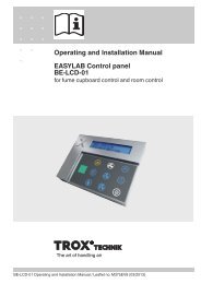
<strong>TROX</strong> GmbHHeinrich Trox Platz47504 Neukirchen-VluynPhone +49(0)2845-202-0Fax +49(0)2845-202-265http://www.trox.dee-mail: trox@trox.deInstalling and commissioning instructions<strong>Velocity</strong> <strong>sensor</strong> <strong>VS</strong>-<strong>TRD</strong>LABCONTROL system<strong>MI</strong>/<strong>7.4</strong>/5/<strong>EN</strong>/2Technical dataPower supply: 24 V AC ±15 %, 50/60 HzTemperature: 10 - 40°COutput:Protection class: IP 201 analog output 2-10 V DCequivalent to 0 - 1 m/sConnector:Phoenix MC 1.5/3-ST-3.81br (br) = Power supply 24 V ACws (wt) = Power supply GNDgn (gn) = Analog output AODimensions:max. casing dimensions: 80 x 90 x 60 mmmax. installation depth: 88.1 mmAttention!Before installing and commissioningread this manual carefully!Scope of application for <strong>VS</strong>-<strong>TRD</strong>The velocity <strong>sensor</strong> <strong>VS</strong>-<strong>TRD</strong> measures the face velocityof fume cupboards and gives an appropriate analogoutput signal with 2-10 V DC.In conjunction with <strong>TROX</strong> volume flow controllers basedon LABCONTROL EASYLAB, TCU-II or TCU-LON-II the<strong>sensor</strong> is used for variable volume flow control.Alternatively the <strong>VS</strong>-<strong>TRD</strong> can be also used in conjunctionwith <strong>TROX</strong> LABCONTROL system TFM-2 for monitoringthe face velocity.The <strong>sensor</strong> <strong>VS</strong>-<strong>TRD</strong> is placed for these functions at asuitable position on the fume cupboard.Please regard the assembling drafts on the following side.Safety instructionsThe installation and wiring must be carried out byqualified and instructed personnel. The country and localspecific guidelines and regulations for electricalinstallations must be observed.During installation, wiring and commissioning, theestablished technical regulations, are to be observed,particulary those on safety and accident prevention.WiringThe transducer is supplied with a prefabricated 3 m cableready-made for plug into the control systems. The green3-pole Phoenix plug must be fitted in the correspondingplug socket on the EASYLAB, TCU-II respectivelyTCU-LON-II controller board. A cable extension with 5 mlength is optionally available.(<strong>TROX</strong> -No. M536BA9)Installing instructions1. Accessibility for further maintenance work must beregarded.2. A hole of ∅ 21-22.5 mm diameter must be drilled inthe top of the fume cupboard.3. The hole diameter must be observed accurately,otherwise measuring errors may occur due to air flowbesides the transducer.Positioning of the hole:For positioning the hole please follow these instructions:1
<strong>TROX</strong> GmbHHeinrich Trox Platz47504 Neukirchen-VluynPhone +49(0)2845-202-0Fax +49(0)2845-202-265http://www.trox.dee-mail: trox@trox.deInstalling and commissioning instructions<strong>Velocity</strong> <strong>sensor</strong> <strong>VS</strong>-<strong>TRD</strong>LABCONTROL system<strong>MI</strong>/<strong>7.4</strong>/5/<strong>EN</strong>/21. There must be enough mounting room for the<strong>VS</strong>-<strong>TRD</strong> at the selected position.2. Inside the fume cupboard the selected area musthave a constant air flow with non turbulent air.(laminar airflow).3. The <strong>VS</strong>-<strong>TRD</strong> should not be exposed to any airstreams outside the fume cupboard.(e.g. installation beneath ceiling diffusers).4. The <strong>VS</strong>-<strong>TRD</strong> should not be installed inside pressureceilings.5. If a pressure difference between the area around thetransducer and the room can be recognized anopening is required as big as necessary to avoid ameasurable airflow.Pressure ceiling notallowed!Opening size seepoint 5 on the left sideThe best possible <strong>sensor</strong> position is shown in thefollowing pictures:Optimal mountingpositionAlternative mounting positionInsertion of the velocity <strong>sensor</strong> into the borehole:1. The velocity <strong>sensor</strong> <strong>VS</strong>-<strong>TRD</strong> should only be insertedinto the borehole of the fume cupboard.2. The <strong>sensor</strong> must not rest onto the fume cupboard.3. Never exceed the given diameter of the borehole.Attention:Exceeding the diameter of the borehole will influence themeasuring negatively!Optimal mountingposition≥ 100 mmAlternativemounting positionsProhibitedmounting positionsImportant:Airtight connection of <strong>sensor</strong> duct and fume cupboardDesign changes reserved · All rights reserved © <strong>TROX</strong> GmbH (02/2010)2