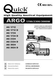
Rev. 001 A Dave 1700/2000/2300/3000/3000TR ... - Quick® SpA
Rev. 001 A Dave 1700/2000/2300/3000/3000TR ... - Quick® SpA
Rev. 001 A Dave 1700/2000/2300/3000/3000TR ... - Quick® SpA

Create successful ePaper yourself
Turn your PDF publications into a flip-book with our unique Google optimized e-Paper software.
MANUTENZIONEITPOS. DENOMINAZIONE CODICE1 Leva salpa piegata ZSLMSHR100002 O-ring bussola PGR0315000003 Bussola Campana MSDFRAG000004 Campana salpa <strong>2000</strong>W Argo SPMSE20AG0R15 Coperchio barbotin SGMSGB20AG006 Anello elastico esterno MBAE3213Y0007 Cono frizione salpa <strong>3000</strong>W sup. MSF30AGS00008A Barbotin <strong>3000</strong>W 10 mm-3/8" compl. ZSB3010380008B Barbotin <strong>3000</strong>W 12-13 mm compl. ZSB30121<strong>3000</strong>8C Barbotin <strong>3000</strong>W 14mm compl. Z S B 3014000R19 Cono frizione salpa <strong>3000</strong>W inf. MSF30AGN00R110 Rondella di rinforzo <strong>3000</strong>W MBR335040X<strong>001</strong>1 Paraolio 35*62*10mm PGPRL35621<strong>001</strong>2 Anello elastico interno MBAN6220Y0<strong>001</strong>3 Cuscinetto 6007 MBJ6007000<strong>001</strong>4 Paraolio 35*50*7mm PGPRL355007015 Freno fascia 4000 W “DV” SPMSVF30DV<strong>001</strong>6 Perno ottone freno fascia <strong>3000</strong>W MSVPF<strong>3000</strong>0<strong>001</strong>7 Perno ottone freno fascia foroM10 <strong>3000</strong>WMSVPF30M10<strong>001</strong>8 Inserto albero freno a fascia “DV” MSVFFDV000<strong>001</strong>9 Albero freno fascia “DV” 4000W MSAS30DV0R0020 Spina 5x18 acciaio inox MBSC05018A0021 Pomello freno fascia serie “DV” MSVPFDV0000022 Rondella Ø 04/12 inox MBR0412X000023 Dado M 6 autobloccante - inox MBD06MXET00024 Carter freno fascia “DV” PDC30DV0000025 Vite M 4*10 Inox MBV0410MXCE026 Chiavetta 10x8x 70 inox MBH1008070X027 Albero serie "DV" <strong>3000</strong>W MSAS30DV0R0128 Chiavetta 10x8x140 inox MBH1008140X029 Albero serie "DV" <strong>3000</strong>W D MSAS30DVDR0130 Vite M 6*50 Inox MBV0650MXCE031 Rondella Ø 06 inox MBR06X00000032 Stacca catena 4000W "DV" SPMSN40DK00033 Perno tendicima <strong>3000</strong>W “DV” MMTC10DV000034A Leva tendicima "DV" X SPMSHLT30AG034B Leva tendicima "DV" Y SPMSHLT30AG035A Molla tendicima salpa <strong>3000</strong>W “DV” X MMTND30DVX0035B Molla tendicima salpa <strong>3000</strong>W “DV” Y MMTND30DVY0036A Coperchio guida catena "DV" X SPMSGG30DVX036B Coperchio guida catena "DV" Y SPMSGG30DVY037 Vite M 4*08 inox MBV0408MXCEB38 Inserto guida catena “DV” inox MSVGCDV0000039 Inserto plast caduta catena<strong>3000</strong>W “DV”MSVPR30AG00040A Supporto guida catena “DV” X SLMSN30DVX0040B Supporto guida catena “DV” Y SLMSN30DVY0041 Vite M 8*16 inox MBV0816MXCE042A Cover base “DV” inox X MSGB15DVX00042B Cover base “DV” inox Y MSGB15DVY00043A Base salpa serie "DV" X SLMSC30DVX0043B Base salpa serie "DV" Y SLMSC30DVY0044 Sensore reed assemblato SAKREED0000045 Prigioniero 10*110 Ø9 inox MBP101109X0046 Rondella Ø10 inox MBR10X00000047 Grower Ø10 inox MBG10X00000048 Dado M10 MBD10MXEN000ATTENZIONE: accertarsi che non sia presente l'alimentazioneal motore elettrico quando si opera manualmentesul salpa ancora; rimuovere con cura lacatena o cima dal barbotin o la cima dalla campana.I salpa ancora Quick ® sono costituiti da materiali resistentiall'ambiente marino: è indispensabile, in ogni caso, rimuovereperiodicamente i depositi di sale che si formano sulle superficiesterne per evitare corrosioni e di conseguenza danni all'apparecchio.Lavare accuratamente con acqua dolce le superfici e le parti incui il sale può depositarsi.Smontare una volta all'anno il barbotin e la campana attenendosialla seguente sequenza:VERSIONE CON CAMPANACon la leva (1) svitare la bussola (3); estrarre la campana (4) edil cono frizione superiore (7); svitare le viti di fissaggio (30) dellostacca catena (32) e rimuoverlo; estrarre il barbotin (8).VERSIONE SENZA CAMPANACon la leva (1) svitare il coperchio barbotin (5) estrarre il conofrizione superiore (7); svitare le viti di fissaggio (30) dello staccacatena (32) e rimuoverlo; estrarre il barbotin (8).Pulire ogni parte smontata affinché non si verifichino attacchidi corrosione e ingrassare (con grasso marino) il filetto dell'albero(27 o 29) e il barbotin (8) dove appoggiano i coni frizione(7 e 9).Rimuovere eventuali depositi di ossido sui morsetti della cassettateleruttori / teleinvertitori; cospargerli di grasso.DAVE <strong>1700</strong>/<strong>2000</strong>/<strong>2300</strong>/<strong>3000</strong>W - IT GB - REV<strong>001</strong>A11
ITMANUTENZIONEPOS. DENOMINAZIONE CODICE50 Guarnizione flangia ridut. TOP TG70 P G F L R D T G 7 0 0 051 Riduttore - <strong>1700</strong>W - serie Quick S L M R 17TG700052 Rondella M BR061815X0053 Dado autobloccante M BD06MXET00054 O-ring riduttore <strong>1700</strong>W P G R0<strong>2300</strong>000055 Chiavetta M BH050515F0056 A Motore <strong>1700</strong>W 12V E M F171<strong>2000</strong>0056 B Motore <strong>1700</strong>W 24V E M F17240000057 Carter motore <strong>1700</strong>W PCCCPM10000058 Guarnizione morsettiera PCGPMMR0000059 Coperchio morsettiera PCCPPMMR000060 Vite MBV02213AXSC61 Guarnizione fondo PGGPMFN0000062 Coperchio fondo PCCPPMFN000063 Passacavi P P M 20B00000064 Riduttore <strong>2000</strong>W M R <strong>3000</strong>00000065 Rondella M BR08X00000066 Vite MBV0825MXE0067 O-ring <strong>2000</strong>W -68 Chiavetta 6x6x30 M BH0606030X069 Motore <strong>2000</strong>W - 24V E M F20240000070 Carter motore <strong>2000</strong>W PCCCPM<strong>2000</strong>0071 O-ring copertura motore P G R03525000072 Coperchio fondo P C C P P M F N <strong>2000</strong>73 Guarnizione morsetteria inf. PCGPMMR2N00074 Guarnizione morsetteria sup. PCGPMMR2S00075 Coperchio morsetteria sup. PCCPPMMR<strong>2000</strong>76 Vite autofilettante M3.9x22 MBV03922AXCC77 Vite autofilettante M3.9x32 MBV03932AXCC78 Riduttore <strong>3000</strong>W - 24V M R <strong>3000</strong>0000079 Guarnizione motoriduttore <strong>3000</strong>W PGBMR<strong>2000</strong>00080 Adattatore motore <strong>2300</strong>W M S L ADMT<strong>2300</strong>081 Chiavetta adattatore 8x7x30 M BH0807030X082 Motore <strong>2300</strong>W 24V E M F20240000083 Motore <strong>3000</strong>W 24V E M F40240000084 Chiavetta 6x6x30 M BH0606030X085 Motore 4000W AC 220/380 E M F402400000MOTORIDUTTORE <strong>1700</strong>MOTORIDUTTORE <strong>3000</strong>5055566162786883635152535457 58605966 6579MOTORIDUTTORE <strong>2000</strong>MOTORIDUTTORE <strong>3000</strong> TR5067686972717778848564666570737475767766 65 79MOTORIDUTTORE <strong>2300</strong>786881827271778077126566797073 747576DAVE <strong>1700</strong>/<strong>2000</strong>/<strong>2300</strong>/<strong>3000</strong>W - IT GB - REV<strong>001</strong>A
USO - AVVERTENZE IMPORTANTIITATTENZIONE: non avvicinare parti del corpo o oggetti alla zona in cui scorrono catena, cima e barbotin. Accertarsi chenon sia presente l'alimentazione al motore elettrico quando si opera manualmente sul salpa ancora (anche quando siutilizza la leva per allentare la frizione); infatti persone dotate di comando a distanza del salpa ancora (pulsantiera remotao radiocomando) potrebbero accidentalmente attivarlo.ATTENZIONE: bloccare la catena con un fermo prima di partire per la navigazione.ATTENZIONE: non attivare elettricamente il salpa ancora con la leva inserita nella campana o nel coperchio del barbotin.ATTENZIONE: Quick ® consiglia di utilizzare una protezione per salvaguardare la linea del motore da surriscaldamentio corto-circuiti. Per correnti alternate (AC) utilizzare un fusibile (il suo dimensionamento è definito nella pagina delloschema di collegamento), per correnti continue (DC) un interruttore specifico e ritardato (magneto termico o magnetoidraulico). L’interruttore può essere utilizzato per isolare il circuito di comando del salpa ancora evitando così azionamentiaccidentali.USO DELLA FRIZIONEIl barbotin è reso solidale all'albero principale (27 o 29) dalla frizione (7 e 9).La frizione si apre (stacco) utilizzando la leva (1) che inserita nella bussola (3) della campana (4) o nel coperchio barbotin (5),dovrà ruotare in senso antiorario. Ruotando in senso orario si provocherà la chiusura (attacco) della frizione.PER SALPARE - Accendere il motore dell'imbarcazione. Assicurarsi che la frizione sia serrata e il freno allentato ed estrarrela leva (1). Premere il pulsante UP del comando a vostra disposizione. Se il salpa ancora si arresta senza che l'interruttore magneto-idraulico(o magnetotermico) sia scattato, attendere qualche secondo e riprovare (evitare una pressione continuata delpulsante). Se l'interruttore magneto-idraulico (o magnetotermico) è scattato, riattivare l'interruttore e attendere qualche minutoprima di riprendere a salpare. Se, dopo ripetuti tentativi, il salpa ancora continua a bloccarsi consigliamo di manovrare l'imbarcazioneper disincagliare l'ancora. Controllare la salita degli ultimi metri di catena per evitare danni alla prua.PER CALARE - La calata dell'ancora si può effettuare tramite comandi elettrici oppure manualmente. Per effettuare l'operazionemanualmente occorre aprire la frizione e allentare il freno, lasciando libero il barbotin di girare sul proprio asse e trascinarela catena o la cima in acqua. Per frenare la caduta dell'ancora bisogna ruotare la leva in senso orario. Per calare l'ancora elettricamenteoccorre premere il pulsante DOWN del comando a vostra disposizione. In questo modo la calata è perfettamentecontrollabile e lo svolgimento della catena o della cima è regolare. Per evitare sollecitazioni sul salpa ancora, una volta ancorati,bloccare la catena con un fermo oppure fissarla ad un punto saldo con una cima.USO DELLA CAMPANAATTENZIONE: Prima di eseguire operazioni di tonneggio, accertarsi che l'ancora e relativa cima o catena siano fissatesaldamente ad una bitta o ad altro punto resistente dell'imbarcazione.Per l'uso indipendente della campana (4), agire sul freno per bloccare il barbotin (8). Con la leva (1) aprire la frizione (almenodue giri della bussola in senso antiorario). Rimuovere la leva dalla bussola (3), avvolgere la cima sulla campana in sensoantiorario (almeno 3 giri). Attivare il comando DOWN del salpa ancora mantenendo in tensione la cima durante il recupero.Variando questa tensione in fase di recupero è possibile modificare la velocità di avvolgimento della cima.ATTENZIONE: durante il recupero, mantenere un'adeguata distanza di sicurezza tra mani e campana salpa ancora.Terminata la procedura di recupero serrare la frizione stringendo la bussola del barbotin in senso orario e assicurare la cima aduna bitta o ad altro punto resistente dell'imbarcazione.DAVE <strong>1700</strong>/<strong>2000</strong>/<strong>2300</strong>/<strong>3000</strong>W - IT GB - REV<strong>001</strong>A13
ITSALPA ANCORA IDRAULICOMODELLO IDRAULICODAVE - / DTipologia motore<strong>Rev</strong>ersibile ad ingranaggiCilindrata 17,9 cc 1,09in3Capacità di sollevamento • 100bar = 600kg • 150bar = 1300kg • 200bar = <strong>1700</strong>kgVelocità di recupero al carico di lavoro (1)40 lt /min = 23 mt/minSpessore coperta (2) 40 ÷ 80 mm 1” 9/16 ÷ 3” 5/32 inchPeso - modello senza campana 39,0 kg 86,0 lbPeso - modello con campana 44,2 kg 97,4 lbVALORI DI REGOLAZIONE (consigliati da Quick)Portata 10-70 lt/min 2,64-19 USGpmPressione [pressione massima] 90 bar [210 bar] 1305,3 psi [3045 psi](1) Misure effettuate con barbotin per catena da 12 mm.(2) Su richiesta possono essere forniti alberi e prigionieri per spessori di coperta maggiori.DIMENSIONI DEL MODELLO IDRAULICO - / D mm ( inch )173(6 7/8)180 (7)227 (8 15/16)239 (9 13/32)228,4 (8)348 (13 45/64)170 (6 3 /4)LA CONFEZIONE CONTIENE: salpa ancora idraulico (top + motoriduttore) - dima di foratura - leva - viterie (per l'assemblaggio)- manuale di istruzioni - condizioni di garanzia.ATTREZZI NECESSARI PER L'INSTALLAZIONE: trapano con punta: Ø 12 mm (15/32"); a tazza Ø 90 mm (3"1/2);chiave esagonale: 17 mm.ACCESSORI QUICK ® CONSIGLIATI: deviatore da pannello (mod. 800) - Pulsantiera stagna (mod. HRC 1002) - Pulsante a piede (mod.900) - Interruttore magneto-idraulico - Conta catena per l'ancoraggio (mod. CHC 1102M e CHC 1202M) - Sistema di comando via radioRRC (mod. R02, PO2, H02).PROCEDURA DI MONTAGGIOPosizionare la parte superiore e collegare a questa la parte inferiore,infilando l'albero nel riduttore.Fissare il salpa ancora avvitando i dadi sui prigionieri di bloccaggio.Collegare i tubi provenienti dalla valvola distributrice alle due flangettedel motore idraulico (vedi schema di collegamento a pag.15).F14Quick ® si riserva il diritto di apportare modifiche alle caratteristiche tecniche dell'apparecchio e al contenuto di questo manuale senza alcun preavviso.In caso di discordanze o eventuali errori tra il testo tradotto e quello originario in italiano, fare riferimento al testo italiano o inglese.DAVE <strong>1700</strong>/<strong>2000</strong>/<strong>2300</strong>/<strong>3000</strong>W - IT GB - REV<strong>001</strong>A
SALPA ANCORA IDRAULICOITSISTEMA BASE DAVE IDRAULICOACCESSORI QUICK ® PER L'AZIONAMENTODEL SALPA ANCORA IDRAULICOSCHEMA DI COLLEGAMENTOPULSANTIERACONTACATENACOMANDODA PLANCIACONTACATENADA PANNELLORADIOCOMANDIRICEVITORETRASMETTITORITASCABILE - PULSANTIERAVALVOLADISTRIBUTRICEINGRESSOPRESSIONESERBATOIO928693MOTORE IDRAULICOPOS. DENOMINAZIONE CODICE41 Riduttore - <strong>2000</strong>W - serie Quick MR<strong>3000</strong>00000064668687908889919266 Vite 3*25 inox MBV0825MXE0086 Grower Ø 8 inox MBG08X00000087 O-ring 2,5*98mm PGRM2598000088 Flangia SGMMGR2B147189 Adattatore Ø19-Ø15 TG70 MSLAD1915H0090 Chiavetta 6*6*25 inox SLMBH060602591 Motore ad ingranaggi 17,9ccbidirezionaleMTG2AR179A0092 Flangetta 90° G3/4 femmina MNFL90F34D4093 Vite 8*30 inox MBV0830MXCE0DAVE <strong>1700</strong>/<strong>2000</strong>/<strong>2300</strong>/<strong>3000</strong>W - IT GB - REV<strong>001</strong>A15
GBTECHNICAL DATAHOW TO IDENTIFY THE WINDLASS THROUGH THE CODE:1° EXAMPLE:DAVE1712DX2° EXAMPLE:DAVE 17 12 D XDAVE 30 24 -DAVE3024Yaaaaaa b c d ea b c daaaaYaea b c dName of the line:[ DAVE ] = oval basein AISI 316 stainless steelMotor output:[ 17 ] = <strong>1700</strong> W[ 20 ] = <strong>2000</strong> W[ 23 ] = <strong>2300</strong> W[ 30 ] = <strong>3000</strong> WMotor supply voltage:[ 12 ] = 12 V[ 24 ] = 24 V[ TR ] = 220 V / 380 VDrum:[ D ] = with drum[ - ] = without drumeChain pipe:[ X ] = right chain pipe[ Y ] = left chain pipeMODELDAVE - / DMOTOR OUTPUT <strong>1700</strong>W <strong>2000</strong>W <strong>2300</strong>W <strong>3000</strong>WMotor supply voltage 12V 24V 24V 24VMaximum pull 1100 Kg (2425,1 lb) 1200 Kg (2645,5 lb) 1260 Kg (2777,8 lb) 2400 Kg (5291,1 lb) 3100 Kg (6834,3 lb)Maximum working load 470 Kg (1036,2 lb) 570 Kg (1256,6 lb) 750 Kg (1653,5 lb) 850 kg (1873,9 lb) 1200 kg (2645,5 lb)Working load 155 Kg (341,7 lb) 190 Kg (418,9 lb) 250 kg (551,1 lb) 285 Kg (628,3 lb) 400 kg (881,8 lb)Current absorption @ working load (1) 175 A 100 A 115 A 120 A 145 AMaximum chain speed (2) m/min 36,1 (118,4 ft/min) 38,3 (125,7 ft/min) 41,2 (135,2 ft/min) 41,2 (135,2 ft/min) 39,2 (128,6 ft/min)Max. chain speed @ working load (2) m/min 20,6 (67,6 ft/min) 20,8 (68,2 ft/min) 22,3 (73,2 ft/min) 23,3 (76,4 ft/min) 19,3 (63,3 ft/min)Deck thickness (3) 40 ÷ 80 mm (1” 9/16” ÷ 3” 5/32)Weight - model without drum 36,8 kg (81,1 lb) 41,8 kg (92,1 lb) 46,8 kg (103,2 lb) 57,5 kg (126,8 lb)Weight - model with drum 42,0 kg (92,6 lb) 47,0 Kg (103,6 lb) 52,0 Kg (114,6 lb) 62,8 Kg (138,4 lb)MODELDAVE - / DMOTOR OUTPUT<strong>3000</strong>W TRMotor supply voltage220/380 VMaximum pull 2800 Kg (6172,9 lb)Maximum working load 930 Kg (2050,3 lb)Maximum chain speed (2) 15,4 m/nm (50,5 ft/min)(1) After an initial period of use.(2) Measurements taken with a gypsy for a 12/13 mm chain.(5) On request, shafts and studs can be supplied for greater deck thicknesses.GYPSY 10 mm - 3/8” 12 - 13 mm 14 mm10 mm 10 mm 3/8” 3/8” 13 mm 12 mm 7/16” 14 mm 1/2”Chain sizeDIN 766 ISO (**) G4 BBB DIN 766 ISO (**) G4 DIN 766 G4Rope size (*) 3/4” 3/4” 3/4”(*) The values in the table refer to a three-strand polyester rope with a rope/chain splice manufactured with the “Quick ® ” system.(**) ISO EN 818-3.Models’ dimensions on page 30/31F16Quick ® reserves the right to introduce changes to the equipment and the contents of this manual without prior notice.In case of discordance or errors in translation between the translated version and the original text in the Italian language, reference will be made to the Italian or English text.DAVE <strong>1700</strong>/<strong>2000</strong>/<strong>2300</strong>/<strong>3000</strong>W - IT GB - REV000A
INSTALLATIONGBBEFORE USING THE WINDLASS READ THESE INSTRUCTIONS CAREFULLY.IF IN DOUBT, CONTACT YOUR NEAREST “QUICK ® ” DEALER.WARNING: the Quick ® windlasses are designed to weigh the anchor. Do not use the equipment for other purposes.Quick ® shall not be held responsible for damage to equipment and/or personal injury, caused by a faulty use of the equipment.The windlass is not designed for the loads that might occur in extreme weather conditions (storms).Always deactivate the windlass when not in use. Check that there are no swimmers nearby before dropping anchor.The splice between the rope and the chain must be tightly woven for the rope to slide easily into the gypsy shape. Forany problem or request, feel free to contact Quick ® Technical Service. For improved safety we recommend installing atleast two anchor windlass controls in case one is accidentally damaged. We recommend the use of the Quick ® hydraulicmagneticswitch as the motor safety switch. Secure the chain with a further device before starting the navigation.The contactor unit or reversing contactor unit must be installed in a point protected from accidental water contact.After completing the anchorage, secure the chain or rope to fixed points such as chain stopper or bollard.To prevent accidental releases, the anchor must be secured. The windlass shall not be used as the only securing device.Isolate the windlass from the power system during navigation (switch the circuit breaker off) and lock the chain securing it toa fixed point of the boat.THE PACKAGE CONTAINS: windlass (on deck unit + motorgearbox) - contactor unit (DV <strong>1700</strong>/<strong>2000</strong>/<strong>2300</strong>W) / reversing contactor unit(DV <strong>3000</strong>W) - base gasket - drill template - handle - bolts and screws (for assembly) - user’s manual - conditions of warranty.TOOLS REQUIRED FOR INSTALLATION: drill and drill bits: Ø 12 mm (15/32"); Ø 90 mm (3"1/2) hollow mill; hexagonal wrenche: 17 mm.“QUICK ® ”ACCESSORIES RECOMMENDED: anchoring RL control board (mod. 800) - Waterproof hand helds R/C (mod. HRC1002)- Foot switch (mod. 900) - Hydraulic-magnetic circuit breaker - Anchor chain counter (mod. CHC1102M and CHC1202M) - Radio controlRRC (mod. R02, PO2, H02).INSTALLATION REQUIREMENTS: the windlass must be positioned with the gypsy aligned with the bow roller. Ensure that theupper and lower surfaces of the deck are as parallel as possible. If this is not the case, compensate the difference appropriately (a lackof parallelism could result in a loss of motor power). The deck thickness must be included among the figures listed in the table. In casesof other thicknesses it is necessary to consult a Quick ® retailer. There must be no obstacles under deck to the passage of cables, ropeand chain; lack of depth of the peak could cause jamming.40 cm (16”)max5 mm(3/16")FITTING PROCEDURE: when the ideal position has been established, drill four holes using the drilling template provided.Remove excess material from the chain passage, refine and flatten with a specialized product (marine paint, gel coat or two pack epoxy)to assure free passage for both rope and chain. Position the upper section, inserting the gasket between the deck and the base andconnect the lower section to the assembly, inserting the shaft into the reduction unit. Fix the windlass by screwing the nuts onto thefixing studs. Connect the supply cables from the windlass to the contactor unit.45°<strong>1700</strong>/<strong>2000</strong>W<strong>2300</strong>/<strong>3000</strong>WWARNING: before wiring up, be sure the electrical cables are not live.DAVE <strong>1700</strong>/<strong>2000</strong>/<strong>2300</strong>/<strong>3000</strong>W - IT GB - REV000AAvailable motorgearboxpositioning17
GBCONNECTION DIAGRAMBASIC SYSTEM DAVE <strong>1700</strong>-<strong>2000</strong>-<strong>2300</strong>WQUICK ® ACCESSORIESRADIO POCKETFOR WINDLASS OPERATIONSEE PAGE 28 SHOWING THE MAINCONNECTION DIAGRAMWATERTIGHT HAND HELDCHAIN COUNTERWINDLASSESCONTROLBOARDMULTI-PURPOSEWATERTIGHT HAND HELDREMOTE CONTROLMOD. HRC 1002WATERTIGHTPANELCHAIN COUNTERREMOTE RADIO CONTROLSRECEIVERTRANSMITTERSWINDLASSRADIO POCKET HANDHELDFOOT SWITCHES MOD. 900U AND 900DBLACKBROWNBLUEL4MOTORBLACKBROWNBLUEHYDRAULIC-MAGNETICCIRCUIT BREAKERBATTERYL1L2L3FUSE4A (12V)2A (24V)L3CONTACTOR UNITMOD. T6315-12 (12V)MOD. T6315-24 (24V)CA2A1L = L1 + L2 + L3 + L418DAVE <strong>1700</strong>/<strong>2000</strong>/<strong>2300</strong>/<strong>3000</strong>W - IT GB - REV000A
CONNECTION DIAGRAMGBBASIC SYSTEM DAVE <strong>3000</strong>WQUICK ® ACCESSORIESRADIO POCKETFOR WINDLASS OPERATIONSEE PAGE 29SHOWING THE MAINCONNECTION DIAGRAMMULTI-PURPOSEWATERTIGHT HAND HELDREMOTE CONTROLMOD. HRC 1002WATERTIGHT HAND HELDCHAIN COUNTERWATERTIGHTPANELCHAIN COUNTERREMOTE RADIO CONTROLSRECEIVERTRANSMITTERSWINDLASSESCONTROLBOARDWINDLASSRADIO POCKET HANDHELDFOOT SWITCHES MOD. 900U AND 900DAABLACKBROWNBLUES SL5MOTORBLACKBROWNBLUEBATTERYHYDRAULIC-MAGNETICCIRCUIT BREAKERL1L3FUSE4A (12V)2A (24V)L2L4L6REVERSINGCONTACTOR UNITMOD. T6415-24 (24V)CA2A1L = L1 + L2 + L3 + L4DAVE <strong>1700</strong>/<strong>2000</strong>/<strong>2300</strong>/<strong>3000</strong>W - IT GB - REV000A19
GBTHREE-PHASE CONNECTION DIAGRAMBASIC SYSTEM DAVE <strong>3000</strong>W 220VWATERTIGHTHAND HELDCHAIN-COUNTERMOD. CHC1102 MWATERTIGHT PANELCHAIN-COUNTERMOD. CHC1202 MWINDLASSCONTROL BOARDMOD. 800MULTI-PURPOSEWATERTIGH HAND HELDREMOTE CONTROLMOD. HRC1002RADIO RECEIVER RRCMOD. R02 (2CH)FOOT SWITCHMOD. 900/DDOWNMOD. 900/UUPUPDOWN+-BLUEBROWNBLACKBLUEBROWNBLACKUPDOWNSENSOR+-CAN LCAN HGREYREDGREENBROWNWHITEBLUEBLACKBLUEBROWNBLACK150CAN LCAN HCAN LCAN HBATTERY 24VL3 XP TFU1 13-25A aMTL2 XP SFU1 13-25A aMSL1XPRFU1 13-25A aMR24VKM124VKM2U1V1W1PEXPR S TXP XP XPU1 V1 W1WINDLASSW2U2V2MOTOR220V CA Max5,5KWSENSORU1 V1 W1M1 TERMINAL BOARD20DAVE <strong>1700</strong>/<strong>2000</strong>/<strong>2300</strong>/<strong>3000</strong>W - IT GB - REV000A
THREE-PHASE CONNECTION DIAGRAMGBBASIC SYSTEM DAVE <strong>3000</strong>W 400VWATERTIGHTHAND HELDCHAIN-COUNTERMOD. CHC1102 MWATERTIGHT PANELCHAIN-COUNTERMOD. CHC1202 MWINDLASSCONTROL BOARDMOD. 800MULTI-PURPOSEWATERTIGH HAND HELDREMOTE CONTROLMOD. HRC1002RADIO RECEIVER RRCMOD. R02 (2CH)FOOT SWITCHMOD. 900/DDOWNMOD. 900/UUPUPDOWN+-BLUEBROWNBLACKBLUEBROWNBLACKUPDOWNSENSOR+-CAN LCAN HGREYREDGREENBROWNWHITEBLUEBLACKBLUEBROWNBLACK150CAN LCAN HCAN LCAN HBATTERY 24VL3 XP TFU1 8 -16A aMTL2 XP SFU1 8 -16A aMSL1XPRFU1 8 -16A aMR24VKM124VKM2U1V1W1PEXPR S TXP XP XPU1 V1 W1WINDLASSMOTOR400V CA Max5,5KWSENSORW2U2V2U1 V1 W1M1 TERMINAL BOARDDAVE <strong>1700</strong>/<strong>2000</strong>/<strong>2300</strong>/<strong>3000</strong>W - IT GB - REV000A21
GBMAITENANCE26126292272835628367303148323738393325 223034915 4024103517161819202122 23111261341421361443454446474822DAVE <strong>1700</strong>/<strong>2000</strong>/<strong>2300</strong>/<strong>3000</strong>W - IT GB - REV000A
MAITENANCEGBPOS. DESCRIPTION CODE1 Bent anchor winch lever ZSLMSHR100002 O-ring bush PGR0315000003 Drum bush MSDFRAG000004 Windlass drum <strong>2000</strong>W SPMSE20AG0R15 Gypsy cover SGMSGB20AG006 External circlip MBAE3213Y0007 Top clutch cone <strong>3000</strong>W MSF30AGS00008A Gypsy <strong>3000</strong>W 10 mm-3/8" compl. ZSB3010380008B Gypsy <strong>3000</strong>W 12-13 mm compl. ZSB30121<strong>3000</strong>8C Gypsy <strong>3000</strong>W 14mm compl. Z S B 3014000R19 Bottom clutch cone <strong>3000</strong>W MSF30AGN00R110 Reinforcement washer <strong>3000</strong>W MBR335040X<strong>001</strong>1 Oil seal 35*62*10mm PGPRL35621<strong>001</strong>2 Internal circlip MBAN6220Y0<strong>001</strong>3 Bearing 6007 MBJ6007000<strong>001</strong>4 Oil seal 35*50*7mm PGPRL355007015 Brake belt 4000 W “DV” SPMSVF30DV<strong>001</strong>6 Brake belt brass pin <strong>3000</strong>W MSVPF<strong>3000</strong>0<strong>001</strong>7 Brake belt brass pin M10 hole <strong>3000</strong>W MSVPF30M10<strong>001</strong>8 Shaft insert brake belt “DV” MSVFFDV000<strong>001</strong>9 Brake belt shaft “DV” 4000W MSAS30DV0R0020 Plug 5x18 stainless steel MBSC05018A0021 Brake belt knob “DV” series MSVPFDV0000022 Washer Ø 04/12 stainless steel MBR0412X000023 Self-locking nuts M 6 - stainless steel MBD06MXET00024 Brake belt casing “DV” PDC30DV0000025 Screw M 4*10 Inox MBV0410MXCE026 Key 10x8x 70 stainless steel MBH1008070X027 Shaft series "DV" <strong>3000</strong>W MSAS30DV0R0128 Key 10x8x140 stainless steel MBH1008140X029 Shaft series "DV" <strong>3000</strong>W D MSAS30DVDR0130 Screw M 6*50 stainless steel MBV0650MXCE031 Washer Ø 06 stainless steel MBR06X00000032 Rope/chain stripper 4000W "DV" SPMSN40DK00033 Mooring rope puller pin <strong>3000</strong>W “DV” MMTC10DV000034A Pressure lever "DV" X SPMSHLT30AG034B Pressure lever "DV" Y SPMSHLT30AG035A Spring for pressure lever<strong>3000</strong>W “DV” XMMTND30DVX0035B Spring for pressure lever<strong>3000</strong>W “DV” YMMTND30DVY0036A Chain guide cover "DV" X SPMSGG30DVX036B Chain guide cover "DV" Y SPMSGG30DVY037 Screw M 4*08 stainless steel MBV0408MXCEB38 Insert for chain guide “DV”stainless steelMSVGCDV0000039 Plastic Insert chain fall<strong>3000</strong>W “DV”MSVPR30AG00040A “DV” chain guide support X SLMSN30DVX0040B “DV” chain guide support Y SLMSN30DVY0041 Screw M 8*16 stainless steel MBV0816MXCE042A Cover base “DV” stainless steel X MSGB15DVX00042B Cover base “DV” stainless steel Y MSGB15DVY00043A Windlass base series "DV" X SLMSC30DVX0043B Windlass base series "DV" Y SLMSC30DVY0044 Assembled sensor reed SAKREED0000045 Stud 10*110 Ø9 stainless steel MBP101109X0046 Washer Ø10 stainless steel MBR10X00000047 Grower Ø10 stainless steel MBG10X00000048 Dado M10 MBD10MXEN000WARNING: make sure the electrical power to themotor is switched off when working manually on thewindlass. Carefully remove the chain or rope from thegypsy or the rope from the drum.Quick® windlasses are manufactured with materials resistantto marine environments. In any case, any salt deposits on theoutside must be removed periodically to avoid corrosion anddamage to the equipment.The parts where salt may have built up should be washedthoroughly with fresh water.Once a year, the drum and the gypsy are to be taken apart asfollows:DRUM VERSIONUse the handle (1) to loosen the bush (3); pull off the drum (4)and the top clutch cone (7); loosen the fixing screws (30) of therope/chain stripper (32) and remove it. Pull off the gypsy (8).NO-DRUM VERSIONUse the handle (1) to remove the gypsy cover (5); remove thetop clutch cone (7); loosen the fixing screws (30) of the rope/chain stripper (32) and remove it. Pull off the gypsy (8).Clean all the parts removed to avoid corrosion, and greasethe shaft thread (27 or 29) and the gypsy (8) where theclutch cones rest (7 and 9) (use grease suitable for marineenvironment).Remove any oxide deposits from the terminals of the electricmotor and the solenoid unit / reversing solenoid; grease them.DAVE <strong>1700</strong>/<strong>2000</strong>/<strong>2300</strong>/<strong>3000</strong>W - IT GB - REV000A23
GBMAINTENANCEPOS. DESCRIPTION CODE50 Gearbox flange gasket Top TG70 P G F L R D T G 7 0 0 051 Gearbox - <strong>1700</strong>W - series Quick S L M R 17TG700052 Washer MBR061815X0053 Self locking nut M BD06MXET00054 O-ring motorgearbox <strong>1700</strong>W P G R0<strong>2300</strong>000055 Key MBH050515F0056 A Electric motor <strong>1700</strong>W 12V E M F171<strong>2000</strong>0056 B Electric motor <strong>1700</strong>W 24V E M F17240000057 Motor casing watertight <strong>1700</strong>W PCCCPM10000058 Grommet PCGPMMR0000059 Terminal board cover PCCPPMMR000060 Screw M BV02213AXSC61 Bottom gasket PGGPMFN0000062 Bottom protec cover PCCPPMFN000063 Cable outlet P P M 20B00000064 Gearbox <strong>2000</strong>W M R <strong>3000</strong>00000065 Washer MBR08X00000066 Screw MBV0825MXE0067 O-ring <strong>2000</strong>W -68 Key 6x6x30 M BH0606030X069 Electric motor <strong>2000</strong>W - 24V E M F20240000070 Motor casing watertight <strong>2000</strong>W PCCCPM<strong>2000</strong>0071 Bottom cover o-ring P G R03525000072 Bottom protec cover P C C P P M F N <strong>2000</strong>73 Lower terminal board gasket PCGPMMR2N00074 Upper terminal board gasket PCGPMMR2S00075 Upper terminal board cover PCCPPMMR<strong>2000</strong>76 Self-tapping screw M3.9x22 MBV03922AXCC77 Self-tapping screw M3.9x32 MBV03932AXCC78 Gearbox <strong>3000</strong>W - 24V M R <strong>3000</strong>0000079 Motorgearbox gasket <strong>3000</strong>W PGBMR<strong>2000</strong>00080 Adaptator <strong>2300</strong>W M S L ADMT<strong>2300</strong>081 Key adaptator 8x7x30 M BH0807030X082 Electric motor <strong>2300</strong>W 24V E M F20240000083 Electric motor <strong>3000</strong>W 24V E M F40240000084 Key 6x6x30 M BH0606030X085 Electric motor 4000W AC 220/380 E M F402400000MOTORGEARBOX <strong>1700</strong>MOTORGEARBOX <strong>3000</strong>5055566162786883635152535457 58605966 6579MOTORGEARBOX <strong>2000</strong>MOTORGEARBOX <strong>3000</strong> TR5067686972717778848564666570737475767766 65 79MOTORGEARBOX <strong>2300</strong>786881827271778077246566797073 747576DAVE <strong>1700</strong>/<strong>2000</strong>/<strong>2300</strong>/<strong>3000</strong>W - IT GB - REV000A
USAGE - WARNINGGBWARNING: stay clear of the chains, ropes and gypsy. Make sure the electric motor is off when windlass is used manually(even when using the handle to disengage the clutch). In fact people with windlass remote controls (hand-held remotecontrol or radio-controlled systems) might accidentally operate it.WARNING: secure the chain with a device before starting the navigation.WARNING: do not operate the windlass by using the electrical power when the handle is inserted in the drum or intothe gypsy cover.WARNING: Quick ® recommends using a protection to prevent the engine line from suffering damages due to overheatingor shortcircuits. For AC currents the use of a fuse is recommended (details on its dimension are specified in the pageof the connection diagram); For DC currents the use of a specific and delayed-action (thermal-magnetic or hydraulicmagnetic)circuit breaker is recommended. The circuit breaker can be used to cut off power to the windlass controlcircuit and so avoid accidental activation.CLUTCH USEThe clutch (7 and 9) provides a link between the gypsy and the main shaft (27 or 29).The clutch can be released (disengagement) by using the handle (1) which, when inserted in the bush (3) of the drum (4) or ofthe gypsy cover (5), must be turned counter-clockwise. The clutch will be re-engaged by turning it clockwise (engagement).WEIGHING THE ANCHOR - Turn on the engine. Make sure the clutch is engaged and the brake is released, remove the handle.Press the UP button on the control provided. If the windlass stops and the hydraulic magnetic switch (or thermal cutout) hasnot tripped, wait a few seconds and try again (avoid keeping the button pressed). If the hydraulic magnetic switch, has tripped,reset it and wait a few minutes before weighing anchor once again. If, after a number of attempts, the windlass is still blocked,we suggest to move the boat to release the anchor. Check the upward movement of the chain for the last few meters in orderto avoid damages to the bow.CASTING THE ANCHOR - The anchor can be cast by using the electrical control or manually. To operate manually, the clutchmust be disengaged and the brake is released allowing the gypsy to revolve and letting the rope or chain fall into the water. Toslow down the chain, the handle must be turned clockwise. To cast the anchor by using the electrical power, press the DOWNbutton on the control provided. In this manner, anchor casting is under control and the chain and rope unwind evenly. In orderto avoid any stress on the windlass -once the boat is anchored- fasten the chain or secure it in place with a rope.DRUM USEWARNING: Before carrying out warping operations, check that the anchor and relative rope or chain are solidly fixed toa bitt or another strong point on the boat.For the independent use of the drum (4), operate on the brake to lock the gypsy (8). Release the clutch with the handle (1),(at least 2 turns of the bush anticlockwise). Remove the handle from the bush (3), wrap the rope around the drum (at least 3turns). Activate the windlass control, keeping the rope under tension during take up. By varying the tension during take up it ispossible to modify the rope winding speed.WARNING: during take up maintain a safe distance between hands and windlass drum.Once take up is complete, screw up the clutch by tightening the gypsy drum clockwise and secure the rope to a bitt or otherstrong point on the boat.DAVE <strong>1700</strong>/<strong>2000</strong>/<strong>2300</strong>/<strong>3000</strong>W - IT GB - REV000A25
GBHYDRAULIC WINDLASSHYDRAULIC MODELDAVE - / DMotor type<strong>Rev</strong>ersible gear-typeMotor power 17,9 cc 1,09in3Lifting capacity • 100bar = 600kg • 150bar = 1300kg • 200bar = <strong>1700</strong>kgMax. chain speed @ working load (1)40 lt /min = 23 mt/minDeck thickness (2) 40 ÷ 80 mm 1” 9/16 ÷ 3” 5/32 inchWeight - model without drum 39,0 kg 86,0 lbWeight - model with drum 44,2 kg 97,4 lbSETTING VALUES (Suggested by Quick)Flow rate 10-70 lt/min 2,64-19 USGpmPression (maximum pression) 90 bar [210 bar] 1305,3 psi [3045 psi](1) Measurements taken with a gypsy for a 12 mm chain.(2) On request, shafts and studs can be supplied for greater deck thicknesses.DIMENSIONS OF HYDRAULIC MODEL - / D mm ( inch )173(6 7/8)180 (7)227 (8 15/16)239 (9 13/32)228,4 (8)348 (13 45/64)170 (6 3 /4)THE PACKAGE CONTAINS: hydraulic windlass (on deck unit + motorgearbox) - drill template - handle - bolts and screws (forassembly) - user’s manual - conditions of warranty.TOOLS REQUIRED FOR INSTALLATION: drill and drill bits: Ø 12 mm (15/32"); Ø 90 mm (3"1/2) hollow mill;hexagonal wrenche: 17 mm.“QUICK ® ”ACCESSORIES RECOMMENDED: anchoring RL control board (mod. 800) - Waterproof hand helds R/C (mod. HRC1002)- Foot switch (mod. 900) - Hydraulic-magnetic circuit breaker - Anchor chain counter (mod. CHC1102M and CHC1202M) - Radio controlRRC (mod. R02, PO2, H02).FITTING PROCEDUREPosition the upper section and connect the lower section to theassembly, inserting the shaft into the reduction unit.Fix the windlass by screwing the nuts onto the fixing studs.Connect the hoses deriving from the selector valve to the flangesof the hydraulic motor (see connection diagram on page 27).F26Quick ® reserves the right to introduce changes to the equipment and the contents of this manual without prior notice.In case of discordance or errors in translation between the translated version and the original text in the Italian language, reference will be made to the Italian or English text.DAVE <strong>1700</strong>/<strong>2000</strong>/<strong>2300</strong>/<strong>3000</strong>W - IT GB - REV000A
HYDRAULIC WINDLASSGBBASIC SYSTEM HYDRAULIC DAVEQUICK ® ACCESSORIESFOR HYDRAULIC WINDLASS OPERATIONCONNECTION DIAGRAMWATERTIGHT HAND HELDCHAIN COUNTERWINDLASSESCONTROLBOARDWATERTIGHTPANELCHAIN COUNTERREMOTE RADIO CONTROLSRECEIVERTRANSMITTERSRADIO POCKET HANDHELDTASCABILE - PULSANTIERASELECTORVALVEPRESSUREINPUTTANK646686928790888991869392HYDRAULIC MOTORPOS. DESCRIPTION CODE41 Gearbox - <strong>2000</strong>W - Quick series MR<strong>3000</strong>00000066 Screw 3*25 stainless steel MBV0825MXE0086 Grower Ø 8 stainless steel MBG08X00000087 O-ring 2,5*98mm PGRM2598000088 Flange SGMMGR2B147189 Adapter Ø19-Ø15 TG70 MSLAD1915H0090 Key 6*6*25 stainless steel SLMBH060602591 Bidirectional gear-type motor 17,9cc MTG2AR179A0092 Flange 90° G3/4 female MNFL90F34D4093 Screw 8*30 stainless steel MBV0830MXCE0DAVE <strong>1700</strong>/<strong>2000</strong>/<strong>2300</strong>/<strong>3000</strong>W - IT GB - REV000A27
RADIO RECEIVER RRCMOD. R02 (2CH)UPDOWN+-BLUEBROWNBLACKMULTI-PURPOSEWATERTIGHHAND HELDREMOTECONTROLMOD. HRC1002BLUEBROWNWINDLASSESCONTROL BOARDMOD. 800BLACKUPDOWNWATERTIGHT PANELCHAIN-COUNTERMOD. CHC1202 MMAIN CONNECTIONDIAGRAMWATERTIGHT HAND HELDCHAIN-COUNTERMOD. 1CHC102 MQUICK WINDLASS®<strong>1700</strong> - <strong>2000</strong> - <strong>2300</strong>WFOOT SWITCHMOD. 900/UUPMOD. 900/DDOWNSENSOR+-CAN LCAN HGREYREDGREENBROWNWHITEBLUEBLACKBLUEBROWNBLACK150CAN LCAN HCAN LCAN HL = L1 + L2 + L3 + L4SENSORA1MOTORL4BATTERYCA2HYDRAULICMAGNETICCIRCUIT BREAKER(see table onpage 4/14)L2L3L1L3FUSE4A (12V)2A (24V)CONTACTORUNITSMOD. T6315-12 (12V)MOD. T6315-24 (24V)28DAVE <strong>1700</strong>/<strong>2000</strong>/<strong>2300</strong>/<strong>3000</strong>W - IT GB - REV<strong>001</strong>A
MAIN CONNECTIONDIAGRAMQUICK WINDLASS®<strong>3000</strong>WSENSORAA- +MULTI-PURPOSEWATERTIGHHAND HELDREMOTECONTROLMOD. HRC1002WINDLASSESCONTROL BOARDMOD. 800WATERTIGHT PANELCHAIN-COUNTERMOD. CHC1202 MWATERTIGHT HAND HELDCHAIN-COUNTERMOD. CHC1102 MFOOT SWITCHMOD. 900/UUPMOD. 900/DDOWNREVERSINGCONTACTOR UNITSMOD. T6415-24 (24V)MOTORL5BATTERYHYDRAULICMAGNETICCIRCUITBREAKER(see table onpage 4/14)L1L2CFUSE4A (12V)2A (24V)A2A1L3L4L6SSRADIO RECEIVER RRCMOD. R02 (2CH)UPDOWN+-BLUEBROWNBLACKBLUEBROWNBLACKUPDOWNSENSOR+-CAN LCAN HGREYREDGREENBROWNWHITEBLUEBLACKBLUEBROWNBLACK150CAN LCAN HCAN LCAN HL = L1 + L2 + L3 + L4 + L5 + L6DAVE <strong>1700</strong>/<strong>2000</strong>/<strong>2300</strong>/<strong>3000</strong>W - IT GB - REV<strong>001</strong>A29
DAVE - DIMENSIONI / DIMENSIONS mm (inch)DAVE <strong>1700</strong> YDAVE <strong>2000</strong> Y348 (13 45/64)239 (9 13/32)228,4 (8)173(6 7/8)227 (8 15/16)172,5(6 51/64)348 (13 45/64)162 (6 1/4)239 (9 13/32)228,4 (8)173(6 7/8)227 (8 15/16)180(7 3/32)170 (6 21/64)375 (14 49/64)407 (16 1/64)DAVE <strong>2300</strong> YDAVE <strong>3000</strong> Y195(7 11/16)173(6 7/8)227 (8 15/16)348 (13 45/64)239 (9 13/32)228,4 (8)205(8 3/32)348 (13 45/64)178 (7)191 (7 1/2)239 (9 13/32)228,4 (8)173(6 7/8)227 (8 15/16)480 (18 29/32)520 (20 15/32)30 DAVE <strong>1700</strong>/<strong>2000</strong>/<strong>2300</strong>/<strong>3000</strong>W - IT GB - REV<strong>001</strong>A
DAVE - DIMENSIONI / DIMENSIONS mm (inch)DAVE <strong>3000</strong> TR YDAVE HYDRO Y348 (13 45/64)239 (9 13/32)228,4 (8)173(6 7/8)227 (8 15/16)244(9 39/64)348 (13 45/64)158 (6 7/32)239 (9 13/32)228,4 (8)173(6 7/8)227 (8 15/16)180 (7)170 (6 3/4)480 (18 57/64)DAVE <strong>1700</strong>/<strong>2000</strong>/<strong>2300</strong>/<strong>3000</strong>W - IT GB - REV<strong>001</strong>A31
NOTES
DAVE<strong>1700</strong>/<strong>2000</strong>/<strong>2300</strong>/<strong>3000</strong>W<strong>3000</strong>TR/HYDROR<strong>001</strong>AITGBCodice e numero seriale del prodottoProduct code and serial numberQUICK ® S.p.A. - Via Piangipane, 120/A - 48124 Piangipane (RAVENNA) - ITALYTel. +39.0544.415061 - Fax +39.0544.415047www.quickitaly.com - E-mail: quick@quickitaly.com