AIR â AMMONIA CONDENSER - Alfa Laval - ABC
AIR â AMMONIA CONDENSER - Alfa Laval - ABC
AIR â AMMONIA CONDENSER - Alfa Laval - ABC

Create successful ePaper yourself
Turn your PDF publications into a flip-book with our unique Google optimized e-Paper software.
<strong>AIR</strong> – <strong>AMMONIA</strong> <strong>CONDENSER</strong>BNM (BNMT, BNMS, BNML, BNMQ, BNMR) and BND (BNDT, BNDS, BNDL, BNDQ, BNDR)INSTRUCTION MANUALIM100528 EN 2007-02
Table of contents• GENERALo To the user.................................................................... page 2o Safety ........................................................................... page 3o Equipment description .................................................. page 4o Table of connections ..................................................... page 7o Delivery ......................................................................... page 91• PROVISIONS FOR MOUNTINGo Unpacking .................................................................... page 10o Layout .......................................................................... page 12EN• MOUNTINGo Piping connections ....................................................... page 14o Electrical Switchboard .................................................. page 16o Electric Installation ....................................................... page 17• MAINTENANCEo Periodic preventive controls ........................................... page 20o Cleaning ....................................................................... page 20o Tools and accessories for maintenance ........................ page 21o Troubleshooting ............................................................ page 21o Replacement of motor ................................................... page 22How to contact <strong>Alfa</strong> <strong>Laval</strong>The contact information for each country, is constantly updated on our website.Visit www.alfalaval.com to get this information.<strong>Alfa</strong> <strong>Laval</strong> reserves the right to change or modify the technical information in this manualwithout notification.
To the UserDear UserThis instruction manual is intended to help you deal with any problems you may encounterwhen using this equipment.<strong>Alfa</strong> <strong>Laval</strong> recommends you to study it carefully, and to make it readily available to anypersonnel who would normally install, operate and maintain the equipment.EN2In the unlikely event that you have a problem not covered in this manual, please do nothesitate to contact your nearest <strong>Alfa</strong> <strong>Laval</strong> representative. We will do our utmost to help youwherever you may be located.<strong>Alfa</strong> <strong>Laval</strong> will not be responsible for any equipment failures which occurdue to failure to consult this manual properly or to the misinterpretation ofthe instructions it contains.Warranty conditions:This equipment is designed to operate properly and to the rated capacity when installed inaccordance with accepted industry standards. Failure to meet the following conditionscould render the system warranty null and void:1. System piping must be installed in accordance with recognized industry standardsand practices.2. Inert gas must be charged into piping during welding.3. The system must be thoroughly leak-checked before initial charging.4. Electrical connections must comply with the following conditions:a. Voltages must not exceed ±5% of nameplate ratings. Frequency 50-60 Hz.b. Current absorption per phase imbalance not to exceed 2%.5. Factory installed wiring must not be changed without <strong>Alfa</strong> <strong>Laval</strong>’s written approval.The hazardous operations and other important information are emphasized in thissection. The warnings are highlighted by means of special signs.Always read this manual before using the equipment!All work on the unit must be carried out by trained staff!ATTENTION! Indicates that special procedures must be followed to avoid seriousinjuresBE CAREFUL! Indicates that special procedures should be followed to avoid seriousdamage to the equipment.NOTE! Indicates important information to simplify operations or to make themmore easy to understand.
SafetyPay ATTENTION! to the following instructions to avoid serious injury to people and /or damage to the equipment.Lifting and Transportation3Lifting forks should be placed under appropriate areas of the wooden shipping skid.Damage may result if the forks come in direct contact with the equipment.ENBefore lifting the equipment1. Ensure that belts or hooks are only attached to the lifting points provided2. Ensure that equipment is stable and properly balanced before lifting.Installation and MaintenanceFluid HazardBefore performing any maintenance operation, the mains power supply should beswitched off, and the safety switch should be in the OFF position to avoidaccidents.No personnel should walk on or step over the equipment, since this risks personalinjury and damage to the equipment.Before attempting maintenance of the fans, make sure they are not running andthe switch is in the OFF position. When the operation is completed, replace thesafety guards.As defined in Annex III of European Union Directive 67/548/EEC, Ammonia is:Flammable Toxic by inhalation Causes burnsAvoid skin contact, liquid NH3, causes chemical burns.As defined in Annexe IV of European Union Directive 67/548/EEC it is recommended to:Wear protective clothingKeep away from sources of ignition - No smoking
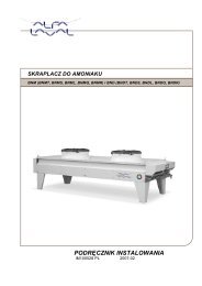
General DescriptionGeneralThis heat exchanger will provide excellent heat transfer, thanks to a combination ofinnovative fin design and the use of stainless steel pipes for fluid flow,EN4Equipment descriptionThis innovative heat exchanger provides excellent heat transfer performance with minimizedrefrigerant charge, thanks to its new fin corrugation, developed by <strong>Alfa</strong> <strong>Laval</strong>. In its standardform, the heat exchanger is manufactured from stainless steel tubes and aluminium finswith 2.3 mm spacing. The case is fabricated from painted galvanized steel sheets while theframe provides the strength and rigidity necessary for heavy-duty applications. These units,BNM and BND, are available with five options of fan motor noise level: (S) standard, (L) low,(Q) quiet, (R) residential and the new (T) high performance fan:Equipment Specifications:Example: BNDQ 905 A DModelBNM Blue Ammonia Condenser BND Blue Ammonia Condenser DoubleNoise levelT =high performance fan S=standard L=low Q=quite R=residentialFan diameter63=630mm, 80=800mm,90=910mm, 100=1000mm80=800mm, 90=910mm, 100=1000mmNumber of fanCoil size1, 2, 3, 4, 5, 6A, B, CMotor ConnectionsMotor typeNumber of polesD=delta Y=starT=three phase S=single phase4P 6P 8P 12P (only single phase motors available for 630 fan diameter)BNM Standard
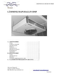
General DescriptionBNM Adjustable Feet Height5ENBND Standard
General DescriptionBND Adjustable Feet Height6ENNOTE !If adjustable feet are used, the height must be sufficient to permit thecorrect air circulation for the size of fan chosen.If in doubt, please consult your <strong>Alfa</strong> <strong>Laval</strong> representative.
General DescriptionDIMENSIONS, WEIGHT AND CONNECTIONS TABLESINGLE ROW <strong>AMMONIA</strong> <strong>CONDENSER</strong>WeightBNMS / BNML BNMQ / BNMR BNMTDim ens ionInlet Outlet Inlet Outlet Inlet Outlet Fans FeetHEIGHT WIDTH DEPTHCode mm mm mm Kg inch inch inch inch inch inch N° N°. 631 A 1225 1625 1215 120 1" 1/2 1" 1" 1/2 1" - - 1 4. 631 B 1225 1625 1215 135 1" 1/2 1" 1" 1/2 1" - - 1 4. 631 C 1225 1625 1215 150 1" 1/2 1" 1" 1/2 1" - - 1 4. 632 A 1225 2715 1215 240 1" 1/2 1" 1" 1/2 1" - - 2 4. 632 B 1225 2715 1215 270 1" 1/2 1" 1" 1/2 1" - - 2 4. 632 C 1225 2715 1215 300 1" 1/2 1" 1" 1/2 1" - - 2 4. 633 A 1225 3805 1215 360 2" 1" 1" 1/2 1" - - 3 4. 633 B 1225 3805 1215 405 2" 1" 1" 1/2 1" - - 3 4. 633 C 1225 3805 1215 450 2" 1" 1" 1/2 1" - - 3 4. 634 A 1225 4895 1215 480 2" 1" 1" 1/2 1" - - 4 6. 634 B 1225 4895 1215 540 2" 1" 1" 1/2 1" - - 4 6. 634 C 1225 4895 1215 600 2" 1" 1" 1/2 1" - - 4 6. 631 Along 1225 1935 1215 150 1" 1/2 1" 1" 1/2 1" - - 1 4. 631 Blong 1225 1935 1215 170 1" 1/2 1" 1" 1/2 1" - - 1 4. 631 Clong 1225 1935 1215 190 1" 1/2 1" 1" 1/2 1" - - 1 4. 632 Along 1225 3335 1215 300 2" 1" 1" 1/2 1" - - 2 4. 632 Blong 1225 3335 1215 340 2" 1" 1" 1/2 1" - - 2 4. 632 Clong 1225 3335 1215 380 2" 1" 1" 1/2 1" - - 2 4. 633 Along 1225 4735 1215 450 2" 1" 1" 1/2 1" - - 3 4. 633 Blong 1225 4735 1215 510 2" 1" 1" 1/2 1" - - 3 4. 633 Clong 1225 4735 1215 570 2" 1" 1" 1/2 1" - - 3 4.801 A 1250 2285 1455 190 1" 1/2 1" 1" 1/2 1" - - 1 4.801 B 1250 2285 1455 215 1" 1/2 1" 1" 1/2 1" - - 1 4.801 C 1250 2285 1455 240 1" 1/2 1" 1" 1/2 1" - - 1 4.802 A 1250 4035 1455 380 2" 1" 1" 1/2 1" - - 2 4.802 B 1250 4035 1455 430 2" 1" 1" 1/2 1" - - 2 4.802 C 1250 4035 1455 480 2" 1" 1" 1/2 1" - - 2 4.803 A 1250 5785 1455 570 2" 1/2 1" 1/2 2" 1" - - 3 4.803 B 1250 5785 1455 645 2" 1/2 1" 1/2 2" 1" - - 3 4.803 C 1250 5785 1455 720 2" 1/2 1" 1/2 2" 1" - - 3 4.804 A 1250 7535 1455 760 3" 2" 2" 1" - - 4 6.804 B 1250 7535 1455 860 3" 2" 2" 1" - - 4 6.804 C 1250 7535 1455 960 3" 2" 2" 1" - - 4 6.805 A 1250 9285 1455 950 3" 2" 2" 1/2 1"1/2 - - 5 8.805 B 1250 9285 1455 1075 3" 2" 2" 1/2 1"1/2 - - 5 8.805 C 1250 9285 1455 1200 3" 2" 2" 1/2 1"1/2 - - 5 8.901 A 1290 2635 1455 230 1" 1/2 1" 1" 1/2 1" 1" 1/2 1" 1 4.901 B 1290 2635 1455 260 1" 1/2 1" 1" 1/2 1" 1" 1/2 1" 1 4.901 C 1290 2635 1455 290 1" 1/2 1" 1" 1/2 1" 1" 1/2 1" 1 4.902 A 1290 4735 1455 460 2" 1" 1" 1/2 1" 2" 1/2 1"1/2 2 4.902 B 1290 4735 1455 520 2" 1" 1" 1/2 1" 2" 1/2 1"1/2 2 4.902 C 1290 4735 1455 580 2" 1" 1" 1/2 1" 2" 1/2 1"1/2 2 4.903 A 1290 6835 1455 690 2" 1/2 1" 1/2 2" 1" 3" 2" 3 4.903 B 1290 6835 1455 780 2" 1/2 1" 1/2 2" 1" 3" 2" 3 4.903 C 1290 6835 1455 870 2" 1/2 1" 1/2 2" 1" 3" 2" 3 4.904 A 1290 8935 1455 920 3" 2" 2" 1" 3" 2" 4 6.904 B 1290 8935 1455 1040 3" 2" 2" 1" 3" 2" 4 6.904 C 1290 8935 1455 1160 3" 2" 2" 1" 3" 2" 4 6.1001 A 1290 2635 1455 230 1" 1/2 1" 1" 1/2 1" - - 1 4.1001 B 1290 2635 1455 260 1" 1/2 1" 1" 1/2 1" - - 1 4.1001 C 1290 2635 1455 290 1" 1/2 1" 1" 1/2 1" - - 1 4.1002 A 1290 4735 1455 460 2" 1/2 1"1/2 2" 1" - - 2 4.1002 B 1290 4735 1455 520 2" 1/2 1"1/2 2" 1" - - 2 4.1002 C 1290 4735 1455 580 2" 1/2 1"1/2 2" 1" - - 2 4.1003 A 1290 6835 1455 690 3" 2" 2" 1/2 1"1/2 - - 3 4.1003 B 1290 6835 1455 780 3" 2" 2" 1/2 1"1/2 - - 3 4.1003 C 1290 6835 1455 870 3" 2" 2" 1/2 1"1/2 - - 3 4.1004 A 1290 8935 1455 920 3" 2" 2" 1/2 1"1/2 - - 4 6.1004 B 1290 8935 1455 1040 3" 2" 2" 1/2 1"1/2 - - 4 6.1004 C 1290 8935 1455 1160 3" 2" 2" 1/2 1"1/2 - - 4 67EN
General DescriptionEN8DIMENSIONS, WEIGHT AND CONNECTIONS TABLEDOUBLE ROW AMM ONIA <strong>CONDENSER</strong>BNDS / BNDL /BNDQ / BNDRDim ensionWeight Inlet Outlet Fans FeetHEIGHT WIDTH DEPTHCode mm mm mm Kg inch inch N° N°..802 A 1250 4035 2255 630 2x2" 2x1" 4 4..802 B 1250 4035 2255 715 2x2" 2x1" 4 4..802 C 1250 4035 2255 800 2x2" 2x1" 4 4..803 A 1250 5785 2255 860 2x2" 2x1" 6 4..803 B 1250 5785 2255 990 2x2" 2x1" 6 4..803 C 1250 5785 2255 1120 2x2" 2x1" 6 4..804 A 1250 7535 2255 1090 2x2" 2x1" 8 6..804 B 1250 7535 2255 1265 2x2" 2x1" 8 6..804 C 1250 7535 2255 1440 2x2" 2x1" 8 6..805 A 1250 9285 2255 1320 2x2" 2x1" 10 8..805 B 1250 9285 2255 1540 2x2" 2x1" 10 8..805 C 1250 9285 2255 1760 2x2" 2x1" 10 8..806 A 1250 11035 2255 1550 2x2" 2x1" 12 8..806 B 1250 11035 2255 1815 2x2" 2x1" 12 8..806 C 1250 11035 2255 2080 2x2" 2x1" 12 8..902 A 1290 4735 2255 830 2x2" 2x1" 4 4..902 B 1290 4735 2255 930 2x2" 2x1" 4 4..902 C 1290 4735 2255 1030 2x2" 2x1" 4 4..903 A 1290 6835 2255 1070 2x2" 2x1" 6 4..903 B 1290 6835 2255 1225 2x2" 2x1" 6 4..903 C 1290 6835 2255 1380 2x2" 2x1" 6 4..904 A 1290 8935 2255 1310 2x2" 2x1" 8 6..904 B 1290 8935 2255 1520 2x2" 2x1" 8 6..904 C 1290 8935 2255 1730 2x2" 2x1" 8 6..905 A 1290 11035 2255 1550 2x2" 2x1" 10 8..905 B 1290 11035 2255 1815 2x2" 2x1" 10 8..905 C 1290 11035 2255 2080 2x2" 2x1" 10 8..1002 A 1290 4735 2255 830 2x2" 2x1" 4 4..1002 B 1290 4735 2255 930 2x2" 2x1" 4 4..1002 C 1290 4735 2255 1030 2x2" 2x1" 4 4..1003 A 1290 6835 2255 1070 2x2" 2x1" 6 4..1003 B 1290 6835 2255 1225 2x2" 2x1" 6 4..1003 C 1290 6835 2255 1380 2x2" 2x1" 6 4..1004 A 1290 8935 2255 1310 2x2" 2x1" 8 6..1004 B 1290 8935 2255 1520 2x2" 2x1" 8 6..1004 C 1290 8935 2255 1730 2x2" 2x1" 8 6..1005 A 1290 11035 2255 1550 2x2" 2x1" 10 8..1005 B 1290 11035 2255 1815 2x2" 2x1" 10 8..1005 C 1290 11035 2255 2080 2x2" 2x1" 10 8
General DescriptionDELIVERYThe equipment is delivered on pallets with the following dimensions:FanDiameterN° ofFansLength A Width B Height C[cm] [cm] [cm]1 185 102 1492 294 102 1496303 403 102 1494 512 102 14991 216 102 1492 356 102 149Single Row630 long3 496 102 1491 251 102 1732 426 102 1733 601 102 173EN4 776 102 1738005 951 102 1731 286 102 1732 496 102 1733 706 102 173900 and 10004 916 102 1734 418 97 2506 593 97 250Double Row8008 768 97 25010 943 97 25012 1118 97 2504 488 97 2506 698 97 2508 908 97 250900 and 100010 1118 97 250Please inspect all equipment upon delivery for any scuff marks or damage to the pallet’s nyloncover that could indicate damage to the equipment itself.In case of damage during transportation, the transportation company and AL (or oneof its agents) must be informed immediately, in writing, on the delivery note.In addition, the customer should send a written report, with accompanying pictures,describing the damage in detail.STORAGEIf the equipment has to be stored before installation (one or more months) the following precautionsare recommended:1. Leave the equipment in its packing.2. Store it indoors, in temperature (15 to 25ºC) and humidity (50 to 70 %).3. Ensure it is not exposed to corrosive liquids or vapours.4. If the equipment is stored outdoors, it is advisable to operate the fan(s), at least onceper week, for 3 to 4 hours at a time, in order to prevent damage to the electric motors.
General DescriptionUNPACKING(This operation should be carried out at heinstallation site)Leave the wrapping on the equipment on the pallet.Single Row10ENDouble RowSizingFollow the procedure below for both Single and Double Row models:1. Lift the equipment as isdone for vertical mounting.2. Lean it on an trestle.3. Remove the liftingeyebolt and the verticalsupporting leg.Lifting eyebolt.
Mounting4. Fix the horizontal legs to the equipment with screws.Let it sit on the load-bearingframe and not on the coil!Lift the unit and secureits legsMove the eyebolt and makesure that it is tightenedbefore lifting the unit11EN5. Lift the equipment placing the hooks as is shown in the figures, according to the differentmodels. Then fix the equipment to the bases with anchor bolts.Use a rocker arm to liftthe unitUse a rocker arm to liftthe unitThe min. lifting angle between thebelts and the unit must be 60°
Mounting optionsLayoutThe following aspects should be considered before mounting:a) Verify the support structure has sufficient strength to take the weight of the equipment.b) Avoid installation in enclosed locations.c) When walls are present, follow the distances recommended by <strong>Alfa</strong> <strong>Laval</strong>.d) Make sure you allow the minimum distances recommended, particularly in installationsinvolving two or more units, either horizontal or vertical (not standard), or in areas exposedto strong winds.EN12YESSingle RowN° UNITS X Y Z2 C/2 C 5002 C C 5003 C 2xC 500>4 2xC 2xC 5002 C 2xC 8502 C/2 C 8503 C 2xC 850>4 C 2xC 850Double RowGRIDN° UNITS X Y Z2 C/2 2xC 5002 C C 5003 C 2xC 500>4 3/2xC 2xC 5002 C/2 C 8503 C 2xC 850>4 3/2xC 2xC 850YESGRIDNONOIn case of doubt or a layout not shown above please contact<strong>Alfa</strong> <strong>Laval</strong>.
Mounting optionsBasesTo avoid corrosion of the equipment’s legs, we recommend that youmount them on concrete bases approximately 4 inches (10 cms.)high (one base for each leg). The base area should be larger thanthe area of the plate on the footVibration dampersFor active and passive isolation of vibrations and to reduce noisetransmission, <strong>Alfa</strong> <strong>Laval</strong> recommends the use of anti-vibrationdampers.13MATERIALIsolator: Natural rubber.Frame: Galvanized steel, with yellow Zinc treatment.Install the anti-vibration attachment between the equipment and thebase.ENVibrations’ IsolatorEach Kit contains 2 units (screws not included)Models Code Num. oflegsQty. ofisolatorsBNMT, BNMS, BNML, BNMQ, BNMRBNDT, BNDS, BNDL, BNDQ,BNDR…631 4 2…632 4 2…633 4 2…634 6 3…631L 4 2…632L 4 2…633L 4 2…801 4 2…802 4 2…803 4 2…804 6 3…805 8 4…901 4 2…902 4 2…903 4 2…904 6 3…1001 4 2…1002 4 2…1003 4 2…1004 6 3…802 4 2…803 4 2…804 6 3…805 8 4…806 8 4…902 4 2…903 4 2…904 6 3…905 8 4…1002 4 2…1003 4 2…1004 6 3…1005 8 4Vertical lifting eyebolts tableEyeboltsModels Code Ømm Qty.BNMT, BNMS, BNML, BNMQ, BNMRBNDT, BNDS, BNDL, BNDQ,BNDR…631 30 4…632 30 4…633 30 4…634 30 4…631L 30 4…632L 30 4…633L 30 4…801 30 4…802 30 4…803 30 4…804 30 4…805 30 8…901 30 4…902 30 4…903 30 4…904 30 4…1001 30 4…1002 30 4…1003 30 4…1004 30 4…802 30 4…803 30 4…804 30 4…805 30 8…806 30 8…902 30 4…903 30 4…904 30 4…905 30 8…1002 30 4…1003 30 4…1004 30 4…1005 30 8
MountingPIPING CONNECTIONSTools and accessories for lifting1-Open end or combination wrenches kit, (sizes from 10 to 20 millimeters).2-Ø 12 mm Steel slings.EN143-Lifting system with capacity according to weight table, page 13.4-Lifting devices:UPN 10 Steel section, length 2 to 3 meters (2 and 4 Fans).UPN 12 Steel section, length 3 to 6 meters (3 and 5 Fans).Steps to follow:1. The provison of suitable external piping for the equipment is the responsibilityof the customer.2. Remove the cover panel before making connections.3. Once the piping has been installed, and before connecting to the equipment,the pipes should be cleaned with compressed air in order to remove anyresidual dirt or welding debris.4. Check the alignment of the piping with the input and output ends of the equipment.Do NOT bend theconnections!Align the piping with theequipment’s connection.
MountingPipeline must be free of mechanical stress and asshort as possible!The following diagram shows the recommended installation:KEYPiping temperature probeEnsure a min. slope of 1% in theliquid line, between the dischargeand liquid receiver.Antivibration dampersCondenserAntivibration jointButterfly valvePiping temp. meterPiping gauge15ENImportant!1. Size the pipes to minimize the pressure drop and to obtain the coolant speed valuesto ensure oil flow.2. In the delivery line, between the compressor and the condenser, install an antivibration device to reduce the noise and vibration transmission along the line.3. Be sure that the line for liquid should have a minimum gradient of 1%, between theliquid discharge and the receiver.Important!Before making the connections, verify the presence of the pre-chargednitrogen for the dry maintenance of the circuit. In the multi-circuit condensersthe refrigerate lines go from LEFT to RIGHT.Welding the pipes:Before welding, disassemble the cap on the ½” gas valve and expel anynitrogen completely.As per prEN 14276-1 and EN 287-1Always wear the correct protective clothing when welding.
Mounting (Optional)Electrical Switchboard16ENSingle switchboardThe equipment is delivered from the factory with the electrical board located in thefinal installation position. A different location will require a different electrical boardand manifold cover plate.
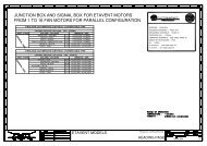
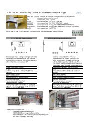
Electric InstallationElectric InstallationThe customer should provide the following electrical connections:Power supplyThree phase : 3 x 400 / 415 Volts – 50 / 60Hz (according to the purchase order)Single phase : 1 x 220 / 230 Volts - 50 / 60 Hz (according to the purchase order)Electric board provision (General Scheme)17ENMain power supplyFree cooling remote signalRemote signal slave mode controlRemote signal speed controller fault_UnitOptional <strong>Alfa</strong> <strong>Laval</strong> deliveryCustomer SupplySupply in according to orderPlease refer to the detailed electrical scheme delivered with the unit.Planning, construction, installation and testing and the use of theelectrical system must be carried out in accordance with Europeanstandards.
Electric InstallationFUNCTIONAL OUTLINE18MAIN SWITCH ON/OFFTk Thermistor included inthe stator’s windingENGroundingAttention: The ground ( earth ) connection is required by lawA ground (earth) connection should be made by connecting a cable from the motor to theequipment casing and from the casing to the ground.Attention: Ground resistance should be lower than 3 ohmsElectric fansThe standard fan motors have the following specifications:· Type: Induction squirrel cage· Protection type: IP 54· Insulation type: F class· S1: Continuous duty· Connectiono 3 Phase – 400 V + - 10% 50 Hz.o Single phase – 230 V + - 10% 50 Hz.
OperationSTARTING THE <strong>CONDENSER</strong>S1. Check all screw and electrical connections.2. Carry out a vacuum phase by connecting to the coupling for equipment loading.3. Load the system with refrigerant gas.4. Start the system and make sure that there are no gas leaks.5. Check that rotation direction agrees with that indicated on the nameplate by running the fan motor for a brief period.6. Check current consumption. The current should be measured after a reasonableperiod of time to ensure that it does not exceed the current indicated on thenameplate.19The starting equipment should be provided with electric overload or power failureprotection with the correct capacity for starting and full load currents. The ground(earth) connection should be made from the equipment structure to the groundedelectrode.ENAvoid frequent stop-start operation of the motor as this will lead to overheating.Direct on-line starts should be limited to 4/hour. Slight differences between actualand rated current and tension values are normal, depending upon the type ofinstallation, the temperature and the altitude above sea level.ShutdownWhen the unit needs to be emptied for maintenance or when not in use, the followingprocedure should be performed:1. Isolate the equipment.2. Collect the refrigerant liquid.3. Disconnect the circuit and flush the equipment with nitrogen.When not in use, leave the equipment loaded with dry nitrogen!Attention! Before attempting any maintenance operation, make sure thatthe power supply is properly disconnected!MaintenanceAttention: Before attempting to carry out any maintenance, the unit should beisolated from the mains power supply. For further safety, the operator can alsoturn the isolator switch to the OFF position.
OperationPeriodic preventive controlsEvery three months the following checks should be performed:EN201. Inspect the equipment fastening.2. Verify that the electrical connection terminal studs are properly tight, to avoid lossesand wear due to sparks.3. Verify the condition of the wiring (it should not have any cuts or other signs ofdeterioration).4. Check the electrical resistance of the ground connection (ohms).5. Use an ammeter to check that the current absorbed is equal to or slightly lower thanthe rated value when the fan(s) work(s) at rated speed.6. Check the fan vibration level.If the equipment is left inoperative for long periods (three or more months),it is advisable to operate the fan(s), at least once a month, for 3 to 4 hours at atime.Cleaning the equipmentTo guarantee the thermal efficiency of the equipment, it is necessary to eliminate the dirtdeposited in the coils, on the suction side. A low pressure water jet and/or non aggressiveliquids can be used.Cleaning is recommended every three months, but this frequency should be altered if thelocation or conditions require it.ACQUA P max < 1.5/2 Bar
MaintenanceTools and accessories for maintenanceo Open end or combination wrenches kit (millimeters), (sizes from 10 to 20mm)o Open end or combination wrench kit (inches), (sizes from ½” to 2”)o Adjustable wrench (3” opening)o Ammetero Voltmeter21Troubleshooting:PROBLEM POSSIBLE CAUSE SOLUTIONCondensation pressure toohigh / outlet fluid temperaturetoo highAir flow to condenser blocked bydirt on the coil with finsDefective fanWrong air flow direction throughthe coilClean the coil with waterand a degreaser or noncorrosive liquidReplaceInvert the rotating directionof the fan, switching two ofthe three phasesENAir temperature too high Contact <strong>Alfa</strong> <strong>Laval</strong>Air temperature too lowAdjust the condenserCondensation pressure too low Excessive air flow through thepressure regulationcondenserFaulty motorReplaceCheck the voltage valueLine voltage lower than tolerancebetween phases with alimitsvoltmeterFans not runningMeasure the voltageLack of a phasebetween phases, check thepower supply lineOverloaded motorCheck with an AmmeterFan break Blockage or shocked Replace
MaintenanceREPLACEMENT OF MOTORSCheck the operation of the electric fans periodically.In the event of electric or mechanical failures, the motor should be replaced as follows:22oooooMake sure that the power supply has been switched off, by placing the switchin the OFF position.Then, open the electric motor derivation box, disconnect and remove the electricwires.Locate the new fan motor and install it.Replace the fan guard.Make the electric connection. Check the fans rotate in the correct direction.ENPanelFan gridTO MINIMIZE POSSIBLE RISKS ALWAYS REFER TO THE FOLLOWING SAFETYCODES:Directive 97/23/CEPressure Equipment Directive.UNI EN 378-1UNI EN 378-2UNI EN 378-3UNI EN 378-4Refrigerating systems and heat pumps - Safety and environmental requirements - Basic requirements, definitions, classification andselection criteria.Refrigerating systems and heat pumps - Safety and environmentalrequirements - Design, construction, testing, marking anddocumentation.Refrigerating systems and heat pumps - Safety and environmentalrequirements - Installation site and personal protection.Refrigerating systems and heat pumps - Safety and environmentalrequirements - Operation, maintenance, repair and recovery.
Montaggio/MountingSostituisce/Replace pag.13Isolatori di vibrazioni<strong>Alfa</strong> <strong>Laval</strong> consiglia vivamente l’impiego di antivibrazioni perisolare l’apparecchiatura sia in modopassivo che attivodalle vibrazioni stesse e per ridurre conseguentemente latrasmissione di eventuali rumori.MATERIALEIsolatore: Gomma naturale 60° ShA.Telaio: Acciaio zincato trattato con zinco giallo.Installare il dispositivo antivibrazioni tra l’apparecchiatura e ilbasamento.(Per l’installazione orizzontale)Vibration isolatorsFor active and passive isolation of vibrations andreducing noise transmission, <strong>Alfa</strong> <strong>Laval</strong> strictlyrecommends the installation of anti-vibration dampers.MATERIALIsolator: Natural rubber 60° ShA.Frame: Galvanized steel, with yellow Zinc treatment.Install the anti-vibration attachment between theequipment and the base.(For Horizontal mounting)Series Model N° FANQty.Of isolatorsKit CodeBNM (T,S,L,Q,R) 630 1 4x60626227 10999345BNM (T,S,L,Q,R) 630 2 4x60626227 10999345BNM (T,S,L,Q,R) 630 3 4x60626227 10999345BNM (T,S,L,Q,R) 630 4 6x60626227 10999346BNM (T,S,L,Q,R) 630L 1 4x60626227 10999345BNM (T,S,L,Q,R) 630L 2 4x60626227 10999345BNM (T,S,L,Q,R) 630L 3 4x60626227 10999345BNM (T,S,L,Q,R) 800 1 4x60626227 10999345BNM (T,S,L,Q,R) 800 2 4x60626227 10999345BNM (T,S,L,Q,R) 800 3 4x60626227 10999345BNM (T,S,L,Q,R) 800 4 6x60626227 10999346BNM (T,S,L,Q,R) 800 5 8x60626227 10999347BNM (T,S,L,Q,R) 900-1000 1 4x60626227 10999345BNM (T,S,L,Q,R) 900-1000 2 4x60626227 10999345BNM (T,S,L,Q,R) 900-1000 3 4x60626031 10999078BNM (T,S,L,Q,R) 900-1000 4 6x60626227 10999346BND (T,S,L,Q,R) 800 2 4x60626227 10999078BND (T,S,L,Q,R) 800 3 4x60626031 10999078BND (T,S,L,Q,R) 800 4 6x60626031 10999079BND (T,S,L,Q,R) 800 5 8x60626031 10999080BND (T,S,L,Q,R) 800 6 8x60626031 10999080BND (T,S,L,Q,R) 900-1000 2 4x60626031 10999078BND (T,S,L,Q,R) 900-1000 3 4x60626030 10999072BND (T,S,L,Q,R) 900-1000 4 6x60626031 10999079BND (T,S,L,Q,R) 900-1000 5 8x60626031 10999080Questi dispositivi antivibrazioni sono forniti sprovvisti di bulloni e dadi. These dampers are delivered without bolts and nutsIM100528 GB-IT 2007-01
page 2/2Schema di montaggioMounting schemeCod. 60626227 Cod. 60626030 Cod. 60626031