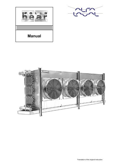
Manual - Alfa Laval - ABC
Manual - Alfa Laval - ABC
Manual - Alfa Laval - ABC

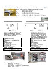
Create successful ePaper yourself
Turn your PDF publications into a flip-book with our unique Google optimized e-Paper software.
<strong>Manual</strong>Translation of the original instruction.
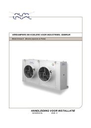
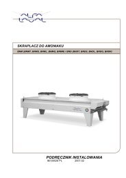
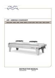
A. Installation Instructions1. GeneralPBZZ air coolers and liquid circulated air coolers are suitable for cold and subzerorooms in refrigeration plants using ammonia, or refrigerants and liquids, which do notcorrode steel.The manual also concerns PBZZE and PBZZGE-model, where applicable (E=nonstandardmodel). In these cases check always from delivery documents, how thedifference effects to the installation and service and use.2. Transports and StoragePBZZ air coolers are delivered in board crates (individual package) or on a flat.During transportation the air cooler feet are fixed to the flat.Coolers may not be stored in humid outdoor spaces.3. LiftingWhen lifting PBZZ air coolers from the bottom, the flat can be used. Coolers may notbe lifted from the bottom of the trip tray without a support from feet. When lifting byhelp of ceiling clamps, all fixing points must be used. The max angle of lifting device is60°. Wrong lifting may cause danger on bending of the equipment, which results inmalfunctions and damages in galvanization.- 2 -Translation of the original instruction.
A. Installation Instructions4. PlacingPBZZ air coolers shall be mounted so that their airflowis not obstructed and there is nothing to prevent it infront of them.It is recommended to leave space at the both ends forservice and cleaning. In the models equipped withelectric defrost (SS) space is needed for changing thedefrost rods of the heat transfer section.The models equipped with textileduct connection (Ft) shall bemounted 3500 mm up fromworking level (SFS-EN 294).These models are delivered withoutsafety guards.When fixing large air coolers to theceiling, the strength of ceilingconstruction and other supportingstructures must be checkedbeforehand.- 3 -Translation of the original instruction.
A. Installation Instructions5. Note at InstallationThe refrigeration plant shall be equipped with a safety device to prevent the exceeding ofthe max. allowed operating pressure.- Before mounting the equipment check at site possible transport damages. Thesupplier is not responsible for the costs caused by broken equipment as aresult of faulty handling or transport.- Air coolers are installed the tubes of heat transfer section in horizontalposition.- Trouble free operation of PBZZG liquid circulated air coolers demands goodair venting in the system.- As to drip tray outlet note that the tray must be opened and removed forcleaning and changing the defrost heater.- Before installation check the endurance of the fixing point constructions.6. Tube ConnectionsLiquid in......................... ALiquid out ...................... BHot gas in ...................... CHot gas out .................... ADrip water out ............... DDefrost water in............... E(Water defrost VS)After connecting to the piping the welded areas must be treated with antirust compound.In models with water defrost (VS) the water distribution basin located on the coil isequipped with spillways. They are located on the fin side, behind the cover plate’s edge.Defrost water amount can be regulated by restricting the water flow so that not toomuch water will run from spillways and that the drip tray does not overflow.- 4 -Translation of the original instruction.
Translation of the original instruction.A. Installation Instructions7. Electric ConnectionsJunction boxes are located in the middle of fans, when fan is outer rotor motor. Fanswith IEC motors have safety switches (Q) located beside each fan (1). Junction box forelectric defrost (SS and SSA) is placed at the same end than tube connections (2). InSS-models the ends are covered with guard plates.8. FansPBZZ are equipped with 3-phase motors according to IEC standards. Alternatively,some fan size can be fan unit with 3-phase outer rotor motor.9. Motor connectionsPBZZ air coolers are equipped with fan motors built to the IEC standards.These motors are not voltage controlled and changing the connectioncannot regulate rotation speed. Fan motors are wired to the safety switch.If the air cooler (non-standard model) has 2-speed fan motors, each speedhas its own safety switch. Connection to the safety switch is shown infigure.- 5 -
Translation of the original instruction.A. Installation InstructionsFans units are 2-speed motors.Changing the connection injunction box from delta to starconnection or on the contraryregulates speed.- 4D= 4-pole deltaconnection = normalspeed 1400 rpm- 4Y= 4-pole starconnection = normalspeed 1150 rpm10. DefrostingFrost is formed into the heat transfer surfaces, when the temperature of the surface isbelow 0°C. Thickness of the frost depends on airflow, humidity and the temperaturedifference between the surface and air. Even thin frost layer have a weakening effect tothermal conductivity for example 1 mm thick layer of frost means 20% less thermalconductivity. Defrost the heat transfer section regularly or when needed. Don’t let theheat transformer freeze up even partly, because this can cause overload of fans andcollapse of heat transfer effect. Length of defrost period have to be so long that thewhole heat transfer section is free from ice. Check the cooler regularly to ensure properdefrosting.Connection of electric heaters:Electric defrost heaters (SS) of heat transfer section and drip tray(SSA) are wired to junction box at the air cooler end. Air coolerswith two or more defrost heaters: electric connection shown infigure.Defrost heater of fan plate (SP) is wired to the junction box locatedbeside each fan. Electric connection as shown in figure.- 6 -
Translation of the original instruction.A. Installation Instructions11. Fan Motor CurrentsThe type plate indicates fan motor current at temperaturesof -30°C and +20°C. For defining the set value ofoverload protector the power value at other temperaturesmight be required. It can be linearly calculated by usingthe above-mentioned points.12. CheckingsThe air coolers have been pressure-tested and the fans test-run at factory. Always checkat site eventual transport damages, especially those in heat transfer section, beforeinstallation. The supplier is not responsible for costs caused by broken equipment as aresult of faulty handling.After electric installations check that the fans run properly and that their rotatingdirection is correct.The customer has to make all measurements and tests (including groundingresistance measurement), which are required in the operating country.- 7 -
Translation of the original instruction.B. Service InstructionsTrouble free operation of PBZZ air coolers and PBZZG liquid circulated air coolersrequire weekly service.WARNING! Before starting service operations make sure that the electric circuit isreliably switched offIn weekly service please check:- Visual condition of the cooler- Fixing of the cooler and its fans- Defrost system- Cleanliness of heat transfer section- Drainage1. Heat Transfer Section and Drip TrayThe heat transfer section needs regular service, when it is in use in dirty conditions orambient conditions require special cleanliness.The heat transfer section can be washed by e.g. a pressure washer. Do not use anydetergents or solvents, which might damage the galvanizing.Check also the visual condition of the heat transfer section.In models designed for ceiling mounting the drip tray can beopened as follows:- Loosen the drip tray outlet- Open the fixing screws of the drip tray (on the finside).Now the drip tray can be opened. Don’t let it open freely,because hinges or drip tray edge can damage. After openingthe heat transfer section can be washed on both sides, thewhole fan box can be cleaned and, if necessary, disinfected.NOTE! In the SS or SSA-model disconnect the cable of the heater before loosening thedrip tray.- 8 -
Translation of the original instruction.B. Service Instructions2. FansThe fan motors, designed for demanding conditions, are squirrel-cage motors built tothe IEC-standards or outer rotor motors.If the fan makes any rattling or scratchy noise, stop it immediately. Replace the motorbearings or the whole motor, if needed. Do not keep the fan motors outdoors or incorresponding conditions for long periods not running.NOTE! During standstills the fans must run 3-4 hours at least once a month.Other fan parts (fan blade, motor bracket, fan guard) do not need any regular service,but check their fixing and visual condition during service, too.3. Replacing a Damaged MotorNOTE! An authorized person may only replace an electric motor.WARNING! Before replacing the fan motor make sure that the circuit is reliablyswitched off!- Switch off the current from safety switch (1)- Release the fan guard by opening four fixing screws (2).- Open the screw at the end of the motor shaft (3).- Loosen the fan blade (4) by an extractor (do not drop a key)- Open the motor's box and make sure that the motor has been switched off(5).- Release the electric cable.- Open the motor's four fixing screws (6)- 9 -
Translation of the original instruction.B. Service Instructions- Lift the motor up- Re-install the motor in reverse order- Push the fan blade at its place by using a screw, not by striking it!- After installation make a test-run to check the fan's rotation direction andother function visually.- Spare part fan shall be delivered by <strong>Alfa</strong> <strong>Laval</strong> Vantaa to ensure its suitability tooperating conditions.4. Changing a Defrost Heater in the Coil (SS)NOTE! An authorized person may only change defrost heaters.- Switch off the current of heaters.- Open the cover plates at both ends (1).- Open the cover of junction box (2).- Make sure that the defrost system has been switched off.- Release cables of the damaged heater couple from the connection strip.- Remove the locking plates of heater rods (3).- Cut off the cable between heater rod couple.- Draw out both parts of heater rod couple.- Pass the rods simultaneously in place. To facilitate this use a thin tube, intowhich the cable fits and which slides through the coil in front of the rod.- When the rods are in position, fasten the locking plates (3)- Fasten electric wires to their original places.- Close the junction box cover and cover plates at the ends.- During the first defrost period make sure that the defrost system works perfectly.5. Changing a Heater Element in the Drip Tray (SS, KK-SSA, VS-SSA or SSA)- Switch off current in defrost system.- Open the junction box cover and make sure that the equipment has beenswitched off.- Release the heating element cable (6) from the box.- Remove the trip tray by opening screws of fixed joints and hinges.- A heater element is glued on the bottom of drip tray- Remove insulated drip tray by removing rivets.- 10 -
Translation of the original instruction.B. Service Instructions- Loosen the male connector from the cable, slacken off the cable clamp (5)and draw the cable (6) through.- Loosen the heating element’s earth conductor (8) from drip tray.- Loosen the old element by drawing from element edge.- Before gluing clean the plate with turpentine and let it dry.- Start gluing at the drip tray end and go on lengthwise to another end.Remove first appr.10 cm of the cover paper, adjust the element (7) and pressthe element head in its place.- Continue gluing by drawing off cover paper and carefully pressing theelement.- Thread the new element’s cable in its place and switch on according tooriginal connecting scheme.- Before installing the insulated drip tray check the correct function of heatingelement.- Alternatively, the new element can be clued over the old one, but no morethan once.- 11 -
Translation of the original instruction.Declaration by the manufacturer of the componentincorporated to the machinery (Directive 2006/42/EC,Annex II, sub.B)ALFA LAVAL VANTAA OYAnsatie 3, FI-01740 Vantaa, Finlandherewith declares that the componentAHB, AMK, ATPE, PBZZ evaporatorAHBG, AMKG, PBZZG air coolerwhich is not able to function independently is intended to be incorporated intomachinery or to be assembled with other machinery to constitute machinerycovered by Directive 2006/42/EC and changes related to it and with nationalimplementing legislation meant machinery.By designing of the component the following directives have been applied:2006/42/EC, 2004/108/EC, 97/23/ECand the following harmonized standards have been applied:ISO-EN 12100:2010, SFS EN ISO 13857, SFS-EN 60204-1,SFS-EN 61000-6-1, SFS-EN 61000-6-3, SFS-EN 61000-6-4Th heat exchanger has been designed according to the directive 97/23/EC andto the conformity assessment procedure for the declaration of conformity, module A1(notified body: Inspecta Tarkastus Oy/CE 0424).Furthermore the manufacturer declares that is not allowed to put the machinery, into whichit is to be incorporated or of which it is to be a component, has been found and declaredto be in conformity with the provisions of Directive 2006/42/EC and with national implementinglegislation including the machinery referred to in this declaration.Vantaa, February 7, 2012Silja BeierschoderQuality Manager