Mathematical Modelling of Transonic Flows in 2D Cascade
Mathematical Modelling of Transonic Flows in 2D Cascade
Mathematical Modelling of Transonic Flows in 2D Cascade

You also want an ePaper? Increase the reach of your titles
YUMPU automatically turns print PDFs into web optimized ePapers that Google loves.
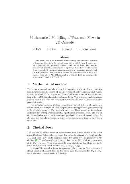
<strong>Mathematical</strong> <strong>Modell<strong>in</strong>g</strong> <strong>of</strong> <strong>Transonic</strong> <strong>Flows</strong> <strong>in</strong><strong>2D</strong> <strong>Cascade</strong>J. Fořt J. Fürst K. Kozel P. PunčochářováAbstractThe work deals with mathematical modell<strong>in</strong>g and numerical solution<strong>of</strong> transonic flows <strong>in</strong> a <strong>2D</strong> cascade near the so-called choked regime us<strong>in</strong>g3 basic models: potential, <strong>in</strong>viscid, and viscous flows. We consideralso several possible formulations <strong>of</strong> upstream boundary conditions forthree types <strong>of</strong> <strong>2D</strong> cascades: a turb<strong>in</strong>e cascade, a compressor cascade andDCA 8% cascade. The numerical results for transonic flows <strong>in</strong> DCA 8%cascade with M ∞ > M ch (Mach number <strong>of</strong> choked flow) are compared toexperimental results <strong>of</strong> IT AS CR.1 <strong>Mathematical</strong> modelsThree mathematical models are used to describe transonic flows: potentialmodel, <strong>in</strong>viscid model described by the system <strong>of</strong> Euler equations and viscousmodel described by the system <strong>of</strong> Navier–Stokes equations either for lam<strong>in</strong>arflow or <strong>in</strong> RANS formulation for turbulent flows. The potential model was consideredboth <strong>in</strong> full form and <strong>in</strong> simplified version known as a small disturbancepotential model.Full potential equation is steady quasil<strong>in</strong>ear partial differential equation <strong>of</strong>second order and changes its type (elliptic-parabolic-hyperbolic type) accord<strong>in</strong>gto local Mach number. The unsteady system <strong>of</strong> Euler equations is nonl<strong>in</strong>earsystem <strong>of</strong> first order partial differential equations <strong>of</strong> hyperbolic type. The system<strong>of</strong> Navier–Stokes equations is nonl<strong>in</strong>ear parabolic system <strong>of</strong> second order. Asobvious, the boundary conditions have to be chosen accord<strong>in</strong>g to the type <strong>of</strong>equations.2 Choked flowsThe problem <strong>of</strong> choked flows for compressible flows is well known <strong>in</strong> <strong>2D</strong>. Fromquasi-1D theory follows, that the mass flow ṁ is a function <strong>of</strong> <strong>in</strong>let Mach numberM ∞ and that there exists maximal mass flow given by the geometry <strong>of</strong> thechannel [2]. Therefore ṁ(M ∞ ) ≤ ṁ max . Denote by M ch1 and M ch2 two roots<strong>of</strong> ṁ(M ∞ ) = ṁ max . Then from quasi-1D analysis follows that there are no <strong>2D</strong>flows with upstream Mach number M ∞ ∈ (M ch1 , M ch2 ).It is possible to realize flows for upstream Mach number M ∞ < M ch1 < 1(Mach number <strong>of</strong> choked flow) on the other hand the solution for M ∞ > M ch1is not obvious. The situation is follow<strong>in</strong>g:
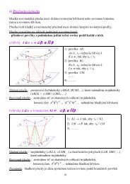
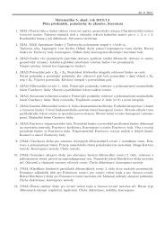
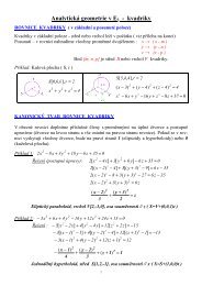
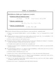
• for turb<strong>in</strong>e cascades one can realize flows with M ∞ < M ch1 with closedsonic l<strong>in</strong>e (i.e. go<strong>in</strong>g from one pr<strong>of</strong>ile to another one, see fig. 1) and it isnot possible to <strong>in</strong>crease M ∞ over M ch1 . Although it is possible to changethe flowfield <strong>in</strong> the outflow part by chang<strong>in</strong>g the outlet pressure p 2 (see[8], [10], [1], [7]).• for transonic compressor cascades there are flows with supersonic <strong>in</strong>letM ∞ > M ch2 > 1 (see fig. 2, [4]).• Mr. Dvořák (IT AS CR) proved experimentally (see [2]) the existence <strong>of</strong>transonic flow <strong>in</strong> impulse turb<strong>in</strong>e DCA 8% cascade with M ∞ ∈ (M ch1 ,M ch2 ) see fig. 3 and 4 show<strong>in</strong>g flow field for M ∞ > M ch1 . Numericallywas this effect confirmed <strong>in</strong> [9] by numerical solution <strong>of</strong> small disturbancepotential equation and <strong>in</strong> [5], [6] us<strong>in</strong>g numerical solution <strong>of</strong> Euler equations.3 DCA 8% cascadeIn this chapter authors show numerical results <strong>of</strong> transonic flows through <strong>2D</strong>DCA 8% 1 cascade compared to experimental results <strong>of</strong> IT AS CR for differentupstream Mach numbers. Authors confirmed the results <strong>of</strong> IT AS CR <strong>in</strong> thesense, that the flow exists also after first choked regime. Numerical results areobta<strong>in</strong>ed us<strong>in</strong>g potential model and the system <strong>of</strong> Euler equations for <strong>in</strong>viscidcompressible flows.3.1 Upstream boundary conditionsThe choice <strong>of</strong> proper upstream boundary conditions depends on the mathematicalmodel.For the case <strong>of</strong> full potential equation as well as for the small disturbance potentialequation one considers usually Dirichlet or Neumann boundary conditionbecause the equation is for M ∞ < 1 elliptic.Similar situation is for the set <strong>of</strong> Navier–Stokes equations which are parabolicand therefore it is aga<strong>in</strong> possible to prescribe Dirichlet or Neumann conditions.On the other hand, the set <strong>of</strong> Euler equations is hyperbolic and the boundaryconditions should be chosen accord<strong>in</strong>g to the sign <strong>of</strong> eigenvalues <strong>of</strong> Jacobians<strong>of</strong> fluxes. In upstream part with M ∞,n = M ∞ cos β < 1 (M ∞,n is the normalMach number computed as a ratio <strong>of</strong> the magnitude <strong>of</strong> velocity componentnormal to <strong>in</strong>let boundary and local speed <strong>of</strong> sound; β is the angle between<strong>in</strong>ward normal and <strong>in</strong>let velocity vector) one eigenvalue is negative and theothers are positive. It means that for correct formulation <strong>in</strong> <strong>2D</strong> three quantitiesshould be prescribed and one should be extrapolated. However, the choice <strong>of</strong> thequantities is somewhat problematic. Consider transonic flows through DCA 8%cascade. In order to compare our numerical results with the experimental dataobta<strong>in</strong>ed at IT AS CR, we have to do the calculation with given <strong>in</strong>let Machnumber. Therefore we consider M ∞ as a given quantity and we extrapolate otherquantity. Another possibility is to keep e.g. <strong>in</strong>let angle and stagnation pressureand stagnation speed <strong>of</strong> sound and to extrapolate M ∞ . It is even possible to use1 DCA 8% pr<strong>of</strong>ile is a blade composed <strong>of</strong> two circular arcs with relative thickness 8%.
Dirichlet conditions for all unknowns due to appearance <strong>of</strong> numerical viscosityterm <strong>in</strong> numerical scheme.Question is what k<strong>in</strong>d <strong>of</strong> boundary condition is better for the case <strong>of</strong> comparisonwith experimental data. When we keep given M ∞ , then the solution isclose to the experimental data. More correct approach with the extrapolation<strong>of</strong> M ∞ does not allow to do the computation with given M. However, it is stillpossible to change the value <strong>of</strong> M ∞ by chang<strong>in</strong>g e.g. <strong>in</strong>let angle.3.2 Numerical simulation <strong>of</strong> flows through DCA 8% cascadeWe considered here flows through DCA 8% cascade with upstream Mach numberclose to M ch and <strong>in</strong>let angle α 1 ≈ 0. Figures 5, 6 show the isol<strong>in</strong>es <strong>of</strong> Machnumber for different upstream Mach number and different models and boundaryconditions. The <strong>in</strong>terest<strong>in</strong>g th<strong>in</strong>g is the change <strong>of</strong> upstream <strong>in</strong>let angle forM ∞ > M ch <strong>in</strong> the case <strong>of</strong> upstream Dirichlet conditions for all variables. Theangle changes to the value α ≈ 5.125 o . When we consider given p 0 , ρ 0 and α 1and we extrapolate M ∞ , we have to iterate the <strong>in</strong>let angle α 1 <strong>in</strong> order to obta<strong>in</strong>flows with M ∞ equal to a desired value. In fact, the <strong>in</strong>let Mach number M ∞is for the case <strong>of</strong> choked flow a function <strong>of</strong> <strong>in</strong>let angle α. After few iterationwe obta<strong>in</strong> correspond<strong>in</strong>g <strong>in</strong>let angle α 1 ≈ 5.125 o (practically the same value asabove).This change <strong>of</strong> upstream angle <strong>of</strong> attack expla<strong>in</strong>s the existence <strong>of</strong> flows afterfirst “chok<strong>in</strong>g” conditions <strong>in</strong> the DCA 8% cascade (see fig. 7).4 Conclud<strong>in</strong>g remarksThis article shows several numerical results <strong>of</strong> choked flows through DCA 8%cascade obta<strong>in</strong>ed by several f<strong>in</strong>ite volume schemes and us<strong>in</strong>g several formulations<strong>of</strong> upstream boundary conditions. The numerical simulation expla<strong>in</strong>s thepossiblity <strong>of</strong> flows with M ∞ > M ch . Those flows were observed also experimentallyat the IT AS CR. The second problem mentioned <strong>in</strong> this article is theproper formulation <strong>of</strong> upstream boundary condition for flows through DCA 8%cascade described by the system <strong>of</strong> Euler equations.Acknowledgement: This work was partly sponsored by the grant GA ČRNo. 201/05/0005 (Kozel, Fořt, Punčochářová) and research plan <strong>of</strong> the M<strong>in</strong>istry<strong>of</strong> Education <strong>of</strong> the Czech Republic No. 6840770010 (Fürst).References[1] J. Dobeš, J. Fürst, J. Fořt, J. Halama, and K. Kozel. Numerical solution<strong>of</strong> transonic flows <strong>in</strong> <strong>2D</strong> and 3D axial and radial turb<strong>in</strong>e cascades. InProceed<strong>in</strong>gs <strong>of</strong> 5th European conference on Turbomach<strong>in</strong>ery, pages 1105–1114, Prague, 2003.[2] Rudolf Dvořák. On the development and structure <strong>of</strong> transonic flow <strong>in</strong>cascades. In Proceed<strong>in</strong>gs <strong>of</strong> ”Symposium Transsonicum II”, pages 297–305.Spr<strong>in</strong>ger-Verlag Berl<strong>in</strong>, 1976.
(a) Experimental result <strong>of</strong> IT AS CR (b) Numerical solution, Eulerequations, unstructured gridFigure 1: Choked flow <strong>in</strong> a turb<strong>in</strong>e cascadeFigure 2: Choked flow <strong>in</strong> a compressor cascade [9]
Figure 3: Sonic l<strong>in</strong>e development [2][3] J. Fořt and K. Kozel. Numerické řešení transonickckého obtékání rov<strong>in</strong>nélopatkové mříže. Strojnický časopis, 35(3), 1984.[4] J. Fořt and K. Kozel. Numerical solution <strong>of</strong> <strong>in</strong>viscid two-dimensional transonicflow through a cascade. In ASME Paper, number 86-GT-19, 1986.[5] J. Fürst, K. Kozel, P. Punčochářová, and P. Šafařík. <strong>Transonic</strong> flowsthrough DCA 8% cascade. In K. Kozel J. Příhoda, editor, Proceed<strong>in</strong>gs <strong>of</strong>”Topical Problems 2005”, pages 61–64. IT CAS CZ, February 2005. ISBN80-85918-92-7.[6] Jiří Fürst. Numerical model<strong>in</strong>g <strong>of</strong> the transonic flows us<strong>in</strong>g TVD and ENOschemes. PhD thesis, ČVUT v Praze and l’Université de la Méditerranée,Marseille, February 2001.[7] Jan Halama, Tony Arts, and Jaroslav Fořt. Numerical solution <strong>of</strong> steadyand unsteady transonic flow <strong>in</strong> turb<strong>in</strong>e cascades and stages. Computersand Fluids, 33:729–740, 2004.[8] Kozel K., Louda P., and Příhoda J. Numerical solution <strong>of</strong> transonic turbulentflow through a turb<strong>in</strong>e cascade. In J. Příhoda K. Kozel, editor,Proceed<strong>in</strong>gs <strong>of</strong> Conference “Topical Problems <strong>of</strong> Fluid Mechanics”, pages73–76, Praha, 2004. IT CAS CZ. ISBN 80-85918-86-2.[9] K. Kozel, J. Polášek, and M. Vavř<strong>in</strong>cová. Numerical solution <strong>of</strong> transonicflow through a cascade with slender pr<strong>of</strong>iles. In Lecture Notes <strong>in</strong> Physics.Spr<strong>in</strong>ger Verlag, 1978.[10] P. Šafařík, M. Štastný, and M. Babák. Numerical and experimental test<strong>in</strong>g<strong>of</strong> transonic flow <strong>in</strong> the etalon turb<strong>in</strong>e cascade SE 1050. In G. BoisM. Štastný, C. H. Sieverd<strong>in</strong>g, editor, 5th European Conference on Turbomach<strong>in</strong>ery.Czech Technical University <strong>in</strong> Prague, 2004.
(a) M ∞ = 0.813, α ∞ = 0 ◦ , p 2 /p ∞ = 1 (b) M ∞ = 0.832, α ∞ = 0 ◦ , p 2 /p ∞ = 1(c) M ∞ = 0.849, α ∞ = 0 ◦ , p 2 /p ∞ = 1 (d) M ∞ = 0.863, α ∞ = 0 ◦ , p 2 /p ∞ = 1(e) M ∞ = 0.946, α ∞ = 0 ◦ , p 2 /p ∞ = 1 (f) M ∞ = 0.982, α ∞ = 0 ◦ , p 2 /p ∞ = 1(g) M ∞ = 1.013, α ∞ = 0 ◦ , p 2 /p ∞ = 1 (h) M ∞ = 1.073, α ∞ = 0 ◦ , p 2 /p ∞ = 1Figure 4: <strong>Transonic</strong> flow development <strong>in</strong> DCA 8% cascade, experimental results<strong>of</strong> IT AS CR [2]
(a) M ∞ = 0.845, α ∞ = 0 ◦ , p 2 /p ∞ = 1 (b) M ∞ = 0.850, α ∞ = 0 ◦ , p 2 /p ∞ = 1(c) M ∞ = 0.930, α ∞ = 0 ◦ , p 2 /p ∞ = 1 (d) M ∞ = 0.950, α ∞ = 0 ◦ , p 2 /p ∞ = 1(e) M ∞ = 1.05, α ∞ = 0 ◦ , p 2 /p ∞ = 1 (f) M ∞ = 1.08, α ∞ = 0 ◦ , p 2 /p ∞ = 1(g) M ∞ = 1.11, α ∞ = 0 ◦ , p 2 /p ∞ = 1 (h) M ∞ = 1.15, α ∞ = 0 ◦ , p 2 /p ∞ = 1Figure 5: <strong>Transonic</strong> flow development <strong>in</strong> DCA 8% cascade, calculation us<strong>in</strong>gcomposite scheme with 40 LW steps followed by one LF step and a mesh with150 × 30 cells [5]
(a) α 1 = 2.5 ◦ , p 2 = 0.48p 0 , (M 1 = 0.863) (b) α 1 = 4.0 ◦ , p 2 = 0.48p 0 , (M 1 = 0.946)(c) α 1 = 4.6 ◦ , p 2 = 0.48p 0 , (M 1 = 0.982) (d) α 1 = 5.2 ◦ , p 2 = 0.48p 0 , (M 1 = 1.013)Figure 6: <strong>Transonic</strong> flow development <strong>in</strong> DCA 8% cascade, calculation us<strong>in</strong>gmodified Causon’s scheme and a mesh with 105 × 30 cells [6](a) Dirichlet conditions for all variables, (b) Extrapolation <strong>of</strong> <strong>in</strong>let pressure,α 1 = 1 o α 1 = 5.17 oFigure 7: Two variants <strong>of</strong> <strong>in</strong>let conditions for DCA 8% cascade with <strong>in</strong>let Machnumber M 1 = 1.08 and p 2 = 0.48p 0