Create successful ePaper yourself
Turn your PDF publications into a flip-book with our unique Google optimized e-Paper software.
Kit IntroductionThank you for purchasing the X-Cell Whiplash by Miniature Aircraft USA. This model is the culmination ofyears of designing and manufacturing R/C helicopters. It is designed with the highest standards, and willprovide years of enjoyment. Whether this is your first R/C model helicopter or you are an advanced R/Chelicopter modeler, the X-Cell Whiplash is a fantastic choice for a “700 size” model.R/C Helicopter SafetyA radio controlled model helicopter is not a toy, but rather a technically complex device that must be builtand operated with care. It is also a fascinating and challenging part of the R/C sport, the mastery of whichis very rewarding. A model helicopter must be built exactly in accordance with the building instructions. Thekit manufacturer has spent much time and effort refining his product to make it reliable in operation and easyto build. The essentially bolt together construction can proceed quite rapidly, giving the builder a strongsense of accomplishment that encourages hasty progress from one construction phase to the next, so thatthe completed model can be more quickly seen and enjoyed. It is essential to recognize and guard againstthis tendency. Follow building instructions exactly. Vibration and stress levels are high and all fasteners andattachments must be secure for safe operation.Note that this is the first use of the word SAFETY in these comments. Previously the kit manufacturer’s effortsto ensure reliable operation were mentioned. That is ALL that he can do. Safe operation is the responsibilityof the builder/flyer and starts with careful construction and continues with selection and installation of reliableradio equipment and engine.The need for safety is nowhere greater than at the flying field. A number of guidelines for safe flight havebeen developed by experienced flyers and are set down here. It is urged that they be read, understood andfollowed.Warning! – Risk of death or serious injuryRemote Control (“R/C”) Helicopters can be dangerous. Inexperienced pilots of R/C Helicopters shouldbe trained and supervised by experienced operators. All operators should use safety glasses and otherappropriate safety equipment. All operators should exercise necessary precautions when fueling, repairing,maintaining, flying and storing R/C Helicopters, and when using or storing R/C Helicopter accessories,equipment, fuels, and related materials. R/C Helicopters should be used only in open areas free of obstaclesand far enough from people to minimize the possibility of injury from the helicopter or any of its componentsfalling or flying in unexpected directions.This helicopter is not a toy but a complex flying machine that must be assembled with care by a responsibleindividual. Failure to exert care in assembly, or radio or accessory installation, may result in a modelincapable of safe flight or ground operation. Rotating components are an ever present danger and source ofinjury to operators and spectators. Since the manufacturer and his agents have no control over the properassembly and operation of his products, no responsibility or liability can be assumed for their use.General Guidelines for Safe R/C Helicopter Flight• Fly only at approved flying fields and obey field regulations.• Follow frequency control procedures. Interference can be dangerous to all.• Know your radio. Check all transmitter functions before each flight.• Be aware that rotating blades are very dangerous and can cause serious injury.• Never fly near or above spectators or other modelers.• If you’re a beginner, get help trimming the model first and flight training later.• Don’t “track” the main blades by holding the tail boom. This is a temptation to builders who cannot hoveryet and is very dangerous.• Follow all recommended maintenance procedures for model, radio and engine.3
Academy of Model AeronauticsMiniature Aircraft USA highly recommends joining the Academy of Model Aeronautics (AMA).• AMA is the Academy of Model Aeronautics.• AMA is the world’s largest model aviation association, representing a membership of more than 150,000from every walk of life, income level and age group.• AMA is a self-supporting, non-profit organization whose purpose is to promote development of modelaviation as a recognized sport and worthwhile recreation activity.• AMA is an organization open to anyone interested in model aviation.• AMA is the official national body for model aviation in the United States. AMA sanctions more than athousand model competitions throughout the country each year and certifies official model flying recordson a national and international level.• AMA is the organizer of the annual National Aeromodeling Championships, the world’s largest modelairplane competition.• AMA is the chartering organization for more than 2,500 model airplane clubs across the country. AMAoffers its chartered clubs official contest sanction, insurance and assistance in getting and keeping flyingsites.• AMA is the voice of its membership, providing liaison with the Federal Aviation Administration, the FederalCommunications Commission, and other government agencies through our national headquarters inMuncie, Indiana. AMA also works with local governments, zoning boards and parks departments topromote the interests of local chartered clubs.• AMA is an associate member of the National Aeronautic Association. Through NAA, AMA is recognized bythe Fédération Aéronautique Internationale (FAI), the world governing body of all aviation activity, as theonly organization which may direct U.S. participation in international aeromodeling activities.For more detailed information, contact the Academy of Model Aeronautics5161 E. Memorial Drive, Muncie, Indiana, 47302or telephone (800) 435-9262.You may also visit the AMA website at www.modelaircraft.org4
Kit ContentsPlease take some time to familiarize yourself with the contents of the kit. The Whiplash kit has been broken down intothree “bags”. Each bag contains parts and hardware. The hardware for each bag will be used only for that bag. Therewill be no left over parts after each bag is assembled. The individual parts of the factory assembled parts are not listedout here. They can be found in the components section of the manual.Bag 1 - Flybarless Kits (MA1032-1)Bag Part No. Part Description Qty1-A 0869 Washout Link 21-A 128-176 Washout Pin 21-A 128-195 Head Button 11-A 128-314 Swashplate Follower 21-A 131-187 Head Axle 11-A 131-190 Damper (80D) 21-A 131-368 FBL Head Block 11-B 0133-1 M3x21.2 Ball Link 101-B 0217 Swashplate 11-B 121-4 Servo To Swash Linkage Rod 31-B 121-7 Swash To PA Linkage Rod 21-B 131-308 FBL Main Shaft 11-C 131-161 Main Blade Grip 21-C 131-163 FBL Pitch Arm 2Bag Part No. Part Description Qty1-Hardware 0021 M4 Lock Nut 11-Hardware 0023 M5 Nut 21-Hardware 0051 M3x3 Set Screw 31-Hardware 0061 M3x8 Socket Bolt 41-Hardware 0063 M3x10 Socket Bolt 21-Hardware 0064-4 M3x16 Button Head Socket Bolt 21-Hardware 0067 M3x14 Socket Bolt 11-Hardware 0082-4 M5x32 Shouldered Socket Bolt 21-Hardware 0086-1 M5x16 Flanged Socket Bolt 21-Hardware 0107 M3x6 Threaded Steel Ball 51-Hardware 0109 M3x8 Threaded Steel Ball 41-Hardware 0447-1 M2 E-clip 21-Hardware 120-7 5x15 C/F Safety Washer 21-Hardware 131-83 Anti-rotation Pin 11-Hardware 131-184 C/F Damper Washer 21-Hardware 131-200 M4x33 Shouldered Socket Bolt 1Bag 1 - Flybar Kits (MA1032)Bag Part No. Part Description Qty1-A 0133-1 M3x21.2 Ball Link 41-A 121-4 Servo To Swash Rod 21-A 128-189 Cage Bar 21-A 128-195 Head Button 11-A 131-155 Cage End 21-A 131-168 FB Head Block 11-A 131-187 Head Axle 11-A 131-190 Damper (80D) 21-B 120-7 5x15 C/F Safety Washer 21-B 128-196 Alumimum Bell Mixer 21-B 131-161 Main Blade Grip 21-B 131-162 FB Pitch Arm 21-B 131-184 9x14x.080 C/F Damper Washer 21-C 0217 Swashplate 11-C 0219 Washout Center Hub 11-C 0869 Washout Link 21-C 106-05 Washout Arm 21-C 128-176 Washout Pin 21-C 131-8 FB Main Shaft 11-D 0133 M2x21.2 Ball Link 21-D 0133-1 M3x21.2 Ball Link 101-D 0135 M2x16.4 Ball Link 2Bag Part No. Part Description Qty1-D 0313 M2x10 Threaded Control Rod 21-D 120-25 Swash To Mixer Linkage Rod 21-D 121-4 Servo To Swash Linkage Rod 3BOX 0303 Flybar 11-Hardware 0021 M4 Lock Nut 11-Hardware 0023 M5 Nut 21-Hardware 0050-1 M2.5 Set Screw 21-Hardware 0051 M3x3 Set Screw 31-Hardware 0057 M4x4 Set Screw 21-Hardware 0061 M3x8 Socket Bolt 41-Hardware 0063 M3x10 Socket Bolt 21-Hardware 0064-3 M3x6 Button Head Socket Bolt 41-Hardware 0067 M3x14 Socket Bolt 11-Hardware 0071 M3x18 Socket Bolt 21-Hardware 0082-4 M5x32 Shouldered Socket Bolt 21-Hardware 0086-1 M5x16 Flanged Socket Bolt 21-Hardware 0091 M3x16 Phillips Machine Bolt 21-Hardware 0107 M3x6 Threaded Steel Ball 51-Hardware 0109 M3x8 Threaded Steel Ball 61-Hardware 0112 M3x9.5 Threaded Steel Ball 41-Hardware 0447-1 M2 E Clip 21-Hardware 131-83 Anti Rotation Pin 11-Hardware 131-200 M4x33 Shouldered Socket Bolt 17
Bag 2 - Tail <strong>Assembly</strong>Bag Part No. Part Description Qty2-A 0133 M2x21.2 Ball Link 22-A 128-144 T/R Control Rod Guide 42-A 131-57 Torque Tube Ends 22-A 131-58 Torque Tube 12-A 131-62 Tail Boom 12-A 131-69-1 T/R Control Rod 12-A 131-80 Torque Tube Bearing Cup 22-A 131-81 Torque Tube Bearing Cup O-ring 42-A 131-86 Assembled Boom Support 22-B 131-34 Front Tail Transmission 12-B 131-35 Boom Clamp W/TX Holes 12-B 131-64 T/R Hub 12-B 131-75 T/R Pitch Slider <strong>Assembly</strong> 12-B 131-112 T/R Blade Grip 22-B 131-129 Tail Box 12-B 131-130 Tail Pitch Control Bellcrank 12-B 131-131 C/F Bellcrank Bracket 12-B 131-132 Bellcrank Slider Cup 1Bag Part No. Part Description Qty2-C 128-80 Front Boom Clamp 12-C 128-149a Upper Rear Boom Support Mount 12-C 128-149b Lower Rear Boom Support Mount 12-C 131-60 C/F Tail Fin 12-C 131-128 C/F Boom Clamp Plate 12-Hardware 0009 M3 Washer 22-Hardware 0016-1 M4 External Serrated Lock Washer 22-Hardware 0019 M3 Lock Nut 22-Hardware 0056 M3x5 Dog-Point Set Screw 22-Hardware 0059-0 M2.5x4 Socket Bolt 62-Hardware 0059-1 M2.5x6 Socket Bolt 12-Hardware 0060-1 M3x6 Socket Bolt 42-Hardware 0061 M3x8 Socket Bolt 32-Hardware 0064-3 M3x6 Button Head Socket Bolt 22-Hardware 0065 M3x12 Socket Bolt 62-Hardware 0067 M3x14 Socket Bolt 22-Hardware 0069 M3x16 Socket Bolt 32-Hardware 0078 M4x12 Socket Bolt 22-Hardware 0107 M3x6 Threaded Steel Ball 4Bag 3 - Electric Frame <strong>Assembly</strong>Bag Part No. Part Description Qty3-A 131-29 C/F X-Brace 13-A 131-47 C/F Servo Rail Spacer 23-A 131-53 C/F Gyro Plate 13-A 131-55 C/F Angled Battery Tray 13-A 131-153 C/F Canopy Breakaway Tabs 43-A 131-186 C/F Anti-rotation Bracket 13-A 132-51 C/F Left Frame - Electric 13-A 132-53 C/F Right Frame - Electric 13-A 132-57 C/F Battery Tray 13-A 132-58 C/F Bottom Plate 13-A 132-59 C/F Front Doubler - Electric 23-A 132-60 C/F Rear Doubler - Electric 23-B 0107 M3x6 Threaded Steel Ball 23-B 128-57 Tray Mount 73-B 128-58 Main Frame Spacer 33-B 131-20 Middle Main Shaft Bearing Block 13-B 131-21 Upper Main Shaft Bearing Block 13-B 131-46 P/A Servo Rail 23-B 131-40 Bottom Main Shaft Bearing Block 13-B 131-52 Delrin Tray Mount 23-B 131-54 M4 Tray Mount 23-B 131-107 T/R Bellcrank Swing Arm 13-B 131-109 Swing Arm Pivot Mount 13-C 131-1 124T Main Gear 13-C 131-24 Main Gear Hub 13-C 131-150 Front Canopy Post 23-C 132-4 Sprag Cup <strong>Assembly</strong> 13-C 132-14 14T Pinion 13-C 132-101 Lower Pinion Bearing Block 13-C 132-100 X-Block/Motor Mount 13-D 0116 M2.5 Threaded Steel Ball 43-D 0133 M2x21.2 Ball Link 23-D 0390 Large Wire Retainers 33-D 106-22 5x11 Grommet 43-D 129-49 9/16” Rubber Wire Grommet 1Bag Part No. Part Description Qty3-D 128-59 M4 Front Boom Support Spacer 13-D 131-50 Elevator Servo Mount 23-D 131-69 M2x315 Linkage Rod 13-D 131-85 C/F Pushrod Sleeve 13-D 131-136 Strut 43-D 131-139 Skid Tubes 23-D 131-148 Servo Plates 123-D 131-151 Rear Canopy Post 23-D 131-154 Thumb Screw 43-D 3200-46 1/2” Hook & Loop Tape 20”3-D 3200-54 Adhesive Back Hook & Loop Tape 12”3-D 3200-56 Battery Straps 43-Hardware 0004 M4 Washer 13-Hardware 0009 M3 Washer - Small 123-Hardware 0016-1 M4 External Serrated Lock Washer 23-Hardware 0017-2 M2.5 Hex Nut 43-Hardware 0021 M4 Lock Nut 13-Hardware 0032 M3 Self Tapping Screw 83-Hardware 0057 M4x4 Set Screw 63-Hardware 0059-1 M2.5 x6 Socket Bolt 43-Hardware 0059-3 M2.5x10 Socket Bolt 163-Hardware 0060-1 M3x6 Socket Bolt 183-Hardware 0061 M3x8 Socket Bolt 623-Hardware 0063 M3x10 Socket Bolt 123-Hardware 0064-3 M3x6 Button Head 123-Hardware 0069 M3x16 Socket Bolt 13-Hardware 0078-4 M4x8 Socket Bolt 43-Hardware 0081 M4x16 Socket Bolt 63-Hardware 0088 M3x8 Tapered Socket Bolt 53-Hardware 131-201 M4x25 Shouldered Socket Bolt 1BOX 131-152 Whiplash Canopy 1BOX 132-230 Whiplash Electric Instruction Manual 1BOX 3000-73 MA Towel 18
MA1032-1 - Flybarless Head <strong>Assembly</strong> Parts0021M4 Hex Locknut0023M5 Hex Locknut0051M3x3 Socket SetScrew0061M3x8 Socket Bolt0063M3x10 Socket Bolt0064-4M3x16 Button HeadSocket Bolt0067M3x14 Socket Bolt0082-4M5x32 ShoulderedSocket Bolt0086-1M5x16 Flanged Bolt0107M3x6 Threaded SteelBall0109M3x8 Threaded SteelBall0133-1M3x21.2 Ball Link01593x7x3 Bearing0217Swashplate0447-1E-Clip0597-4M3x4.75x.215 BrassSpacer08693D Washout Link120-7M5x15 Carbon FiberSafety Washer121-4M3x30 ThreadedControl Rod121-7M3x65 ThreadedControl Rod128-176M2x.584 WashoutPivot Pin128-195Aluminum Head Button128-314Swashplate Follower131-83Swashplate Pin131-161Aluminum Blade Grip131-163Aluminum Pitch Arm131-1819x17x5 Bearing131-1829x17x5 Thrust Bearing131-1839x14x.75 Washer131-184Carbon Fiber DamperWasher131-187Head AxleHardware forthis assembly0051M3x3 Socket SetScrew131-190Damper (80D)131-200M4x33 ShoulderedSocket Bolt0051131-308Flybarless Main Shaft0109131-368Flybarless Head BlockApply a small amount ofmedium thread lock whenthreading into metal parts01090107M3x6 ThreadedSteel Ball0109M3x8 Threaded SteelBall0051021701070107131-83Swashplate Pin0109<strong>Assembly</strong> Tip• Install MA0051 M3x3 Socket SetScrews only until they bottom outagainst the lower bearing. No notovertighten or damage to swashplatebearing will occur.90107131-830109
Hardware forthis assembly131-1900067128-1950064-4M3x16 Button HeadSocket Bolt0067M3x14 Socket Bolt0447-1E-clip131-190Applygrease toHead Axle131-187128-176M2x.584 WashoutPivot Pin128-176131-3680869<strong>Assembly</strong> TipX2• The use of a light grease such asMA3200-06 Tri-Flow Synthetic Greaseis required for damper/head axlelubricationHardware forthis assembly0107M3x6 ThreadedSteel Ball0061M3x8 Socket HeadCap Screw0086-1M5x16 Flanged Bolt0447-10064-4X201590597-4128-3140159 Factory Installed131-161Apply a small amount ofmedium thread lock whenthreading into metal parts120-7M5x15 Carbon FiberSafety Washer0107131-1839x14x.75 Washer131-163131-184Carbon Fiber DamperWasher0061131-184131-181Bearings Factory Installedin Blade Grips<strong>Assembly</strong> Tips• The use of a light greasesuch as MA3200-06 Tri-FlowSynthetic Grease is requiredfor thrust bearing lubrication(pre-applied and assembledfrom factory)131-182131-183131-181120-7• 3 piece thrust bearing(MA131-182) outer race withlarger I.D. (inside diameter)installs closest to hub.10LargeI.D.SmallI.D.0086-1
Hardware forthis assembly0082-40021M4 Hex Locknut0023M5 Hex Locknut0063M3x10 Socket Bolt0082-4M5x32 ShoulderedSocket Bolt0023131-2000063131-200M4x33 ShoulderedSocket Bolt002100230063131-308Link ArmLengths andInstallationApply a small amount ofmedium thread lock whenthreading into metal partsX20133-147.5mmX3121-70133-113.5mm121-40133-10133-111
MA1032 - Flybar Head <strong>Assembly</strong> Parts0021M4 Hex Locknut0023M5 Hex Locknut0050-1M2.5x3 Socket SetScrew0051M3x3 Socket SetScrew0057M4x4 Socket SetScrew0061M3x8 Socket Bolt0063M3x10 Socket Bolt0064-3M3x6 Button HeadSocket Bolt0067M3x14 Socket Bolt0071M3x18 Socket Bolt0078-3M4x6 Socket Bolt0082-4M5x32 ShoulderedSocket Bolt0086-1M5x16 Flanged Bolt0091M3x16 Machine Bolt0107M3x6 Threaded Steel Ball0109M3x8 Threaded Steel Ball0112M3x9.5 Threaded SteelBall0133M2x21.2 PlasticBall Link0133-1M3x21.2 PlasticBall Link0135M2x16.4 PlasticBall Link01593x7x3 Bearing0217Swashplate0219Washout Center Hub02836x10x3 Flanged Bearing0303M4x17.75” Flybar0313M2x10 ThreadedControl Rod0447-1E-clip0840-27Washout Head Pin08693D Washout Link106-023x7x3 Flanged Bearing106-05Aluminum Washout Arm106-062x5x.5 Flanged Bearing120-7M5x15 Carbon FiberSafety Washer120-25M2.6x86 ThreadedControl Rod121-4M3x30 Threaded ControlRod122-28M3x.125”x.79” BrassSpacer128-176M2x.584 Washout PivotPin128-189Flybar Control Bar128-196Aluminum Bell Mixer128-195Aluminum Head Button131-8Flybar Main Shaft131-83Swashplate Pin131-155Flybar Cage End131-157Flybar Cross Tube131-161Aluminum Blade Grip131-162Flybar Pitch Arm131-1664x8x3 Flanged Bearing131-168Flybar Head Block131-1819x17x5 Bearing131-1829x17x5 Thrust Bearing131-1839x14x.75 Washer131-184Carbon Fiber DamperWasher131-187Head Axle131-190Damper (80D)12131-200M4x33 ShoulderedSocket Bolt
Hardware forthis assembly 00510051M3x3 Socket SetScrew0107M3x6 ThreadedSteel Ball010901120109M3x8 Threaded SteelBall0112M3x9.5 ThreadedSteel Ball0051021701070107131-83Swashplate Pin0112<strong>Assembly</strong> Tip• Install MA0051 M3x3 Socket SetScrews only until they bottom outagainst the lower bearing. No notovertighten or damage to swashplatebearing will occur.Hardware forthis assembly106-0501090107131-830109Apply a small amount ofmedium thread lock whenthreading into metal parts0071M3x18 Socket Bolt0109M3x8 Threaded SteelBall0447-1E-clipFactory Installed0159122-28106-02128-176M2x.584 WashoutPivot Pin0219106-06(factory installed)X2<strong>Assembly</strong> Tip00710447-1128-176• Do not overtighten MA0071 SocketBolt into plastic Washout Center Hub.Hardware forthis assembly0109 0050-1(Install last)0869131-161Apply a small amount ofmedium thread lock whenthreading into metal parts0050-1M32.5x3 Socket SetScrewFactoryInstalled106-02131-162X20061M3x8 Socket Bolt106-020091M3x16 Machine Bolt0107M3x6 ThreadedSteel Ball0109M3x8 Threaded SteelBall0091122-280107128-196006113
131-184Bearings Factory Installedin Blade GripsX2131-181131-182131-183131-181Hardware forthis assembly0021M4 Hex Locknut0057LargeI.D.SmallI.D.120-70086-10057M4x4 Socket SetScrew00210063M3x10 Socket Bolt0067M5x16 Flanged Bolt120-7M5x15 Carbon FiberSafety Washer0063131-184Carbon Fiber DamperWasher0303131-200131-1839x14x.75 Washer0063131-200M4x33 ShoulderedSocket BoltWashout Links installonto longer MA0112Threaded Steel Balls<strong>Assembly</strong> Tips• The use of a light grease suchas MA3200-06 Tri-Flow SyntheticGrease is required for thrustbearing lubrication (pre-applied andassembled from factory)• 3 piece thrust bearing (MA131-66)outer race with larger I.D. (insidediameter) installs closest to hub.• Ensure equal lengths of MA0303Flybar extended out of the flybarcontrol assembly.15131-8
Hardware forthis assembly0023M5 Hex Locknut0082-40082-4M5x32 ShoulderedSocket Bolt002301330023031301350133-1120-250133-1121-40133-10133-172.5mmX219mm32mmX3X216
Tail <strong>Assembly</strong> Parts00093mm Flat SteelWasher0012-2M3 Pem Nut0016-100194mm External 3mm Hex LocknutSerrated Lockwasher0051M3x3 Socket SetScrew0056M3x5 Dog PointSocket Screw0058-3M4x16 Socket SetScrew0059-0M2.5x4 Socket Bolt0059-1M2.5x6 Socket Bolt0060-1M3x6 Socket Bolt0061M3x8 Socket Bolt0064-3M3x6 Button HeadSocket Bolt0065M3x12 Socket Bolt0067M3x14 Socket Bolt0069M3x16 Socket Bolt0078M4x12 Socket Bolt0107M3x6 ThreadedSteel Ball0133M2x21.2 Ball Links01593x7x3 Bearing0215Auto Hub Ret. Collar0225Pivot Pin ForPitch Links0273M6x10x.011” SteelShim Waasher03198x16x5 Bearing0442Pivoting T/R PitchLink0597-13x4.75x.126 BrassSpacer120-395x10x4 Bearing122-70M.5x.25 Shim127-86M6x9.7x1.0 ShimWasher128-80Aluminum FrontBoom Clamp128-144T/r Control RodGuides128-149Rear Boom SupportMount128-146Aluminum BoomSupport Ends131-15Tail Drive Gear131-17Tail Bevel Gear,Shaft Side131-18Tail Bevel Gear,Torque Tube Side131-236x13x5 Bearing131-3315x21x4 Bearing131-34Front Tail DriveTransmission131-35 Boom ClampW/transmission Holes131-51Jack Shaft131-57Torque Tube End131-58Torque Tube131-60Carbon Fiber VerticalTail Fin131-62Aluminum Tail Boom131-64Tail Hub131-665x10 Thrust Bearing131-69-1Tail Linkage Rod131-70Tail Rotor OutputShaft131-71Tail Pitch Yoke131-72Brass Slider131-737x11x3 Bearing131-74Pitch Slider Ring131-80Torque Tube BearingCup131-81Torque Tube BearingCup O-ring131-84Carbon BoomSupport Rod131-86Tail Boom Support<strong>Assembly</strong>131-112T/r Blade Grip131-128Carbon Fiber BoomClamp Plate131-129Tail Case131-130Tail Bellcrank17131-131Carbon Fiber BellcrankBracket131-132Bellcrank Cup131-135Bracket Washer
Hardware forthis assembly0107M3x6 ThreadedSteel Ball0225044202250225Pivot Pin for WashoutArm131-71FactoryAssembled131-74131-730107(not factory installed)131-72Hardware forthis assemblyFactory AssembledApply a small amount ofmedium thread lock whenthreading into metal parts0051M3x3 Socket SetScrew0056 M3x5 Dog PointSocket Screw131-1290273m6x10x.11” SteelShim Washer131-23131-33Factory Assembled131-70131-1800510056<strong>Assembly</strong> Tip• Make sure to include MA0273 ShimWasher between MA131-17 OutputGear and transmission case bearing.0215131-170273180056
Hardware forthis assembly0059-1M2.5x6 Socket Bolt0064-3M3x6 Button HeadSocket Bolt0069M3x16 Socket Bolt0107M3x6 ThreadedSteel Ball0064-3010700690159131-1300597-101590059-1131-135131-1310012-2FactoryAssembled131-132(This part is notfactory installed)FactoryAssembled<strong>Assembly</strong> Tip• The use of a light oil such asMA3200-02 Tri-Flow Oil is requiredfor tail rotor output shaft/pitchslider lubricationHardware forthis assembly00093mm Flat Steel Washer00193mm Hex Nut0061M3x8 Socket BoltX2131-112Apply oil tooutput shaft0019LargeI.D.SmallI.D.Apply a small amount ofmedium thread lock whenthreading into metal parts0009120-39122-70131-6600610069M3x16 Socket Bolt010700690107M3x6 ThreadedSteel Ball122-70M.5x.25 Shim120-39BearingsFactory Installedin Blade Grips<strong>Assembly</strong> Tips131-64• 3 piece thrust bearing (MA131-66)outer race with larger I.D. (insidediameter) installs closest to hub.• Grease the center ball cage of thethrust bearing. We recommend usingMA3200-06 Tri-Flow synthetic grease.• Only hand tighten MA0061 SocketBolt until it is moderately tight. Donot overtighten bolt or it may result infatigue to bolt. Use green thread lockon these bolts.19
Hardware forthis assembly0056M3x5 Dog PointSocket Screw0056<strong>Assembly</strong> Tip0056• Ensure the dog point tip is seatedinto the dimples on the tail rotorshaft.Hardware forthis assembly0056M3x5 Dog PointSocket Screw0065M3x12 Socket Bolt131-350065Apply a small amount ofmedium thread lock whenthreading into metal parts131-180273M6x10x.011” SteelShim Washer127-86M6x9.7x1.0 ShimWasher0065Factory Assembled127-860056131-33131-150056131-230056131-170273131-34131-5120
Hardware forthis assembly131-8003190059-0M2.5x4 Socket Bolt131-81BearingsFactory Installedin Bearing CupX2NOTE: Install both bearing cupassemblies facing the samedirection on torque tube.0059-0X2131-58131-570059-0265mm250mmNOTE: Carefully CA glue bearing assemblies to torque tube making sure bearing locations are NOT equaldistances from torque tub ends. Use only a very small amount of thin to medium CA ensuring no CA seepsinto the bearing. Allow CA glue to dry before installing into tail boom.Hardware forthis assembly0067Apply a small amount ofmedium thread lock whenthreading into metal parts00670060-1M3x6 Socket Bolt0060-10060-10067M3x14 Socket BoltEnd of the boom with the3mm hole 1mm from theend of the boom<strong>Assembly</strong> Tips131-128• Ensure that the boom is full insertedthrough boom clamps.• Do not overtighten MA0067 SocketBolts as it is possible to crush tailboom.131-6221128-80
<strong>Assembly</strong> Tips• Use some light oil such as Tri-Flowinto tail boom to ease installation fortorque tube assembly.• Install the torque tube with the openends of the bearing cups towards theback of the tail boom assembly. Thiswill ensure the bearing stays seatedin the bearing cup.• Push Torque Tube all the way intoTorque Tube Gear, then back out1/16” (1.5mm) so Torque Tube andgear can “float”.• Install MA128-144 T/R Control RodGuides with the dimples towardsfront of tail assembly. Use a smallamount of cyanoacrylateglue to ensure eachguide stays inposition.128-144131-69-101330133Hardware forthis assembly105mm Tail Rotor Blades(not included)Apply a small amount ofmedium thread lock whenthreading into metal parts0016-1 4mmExternal SerratedLockwasher0060-1M3x6 Socket Bolt0061M3x8 Socket Bolt0065M3x12 Socket Bolt00610060-10078M4x12 Socket Bolt0065128-1490065<strong>Assembly</strong> Tips• The use of “green” thread lock suchas MA3200-22 is recommended onMA0078 Socket Bolts.• Do not overtighten MA0065 SocketBolts on the Rear Boom SupportMounts.• Aluminum boom support ends havea dimple on one side. The dimpleindicates a slight angle built in to thispart. On the Boom support assemblyside that attaches to the main frame,the dimple will be facing “in”.0016-10078131-86(Factory Assembled -includes MA0058-3,MA128-146 & MA131-84)131-6022
Electric Frame <strong>Assembly</strong> Parts0004M4 Washer00093mm Flat SteelWasher0012-12.5mm Pem Nut0012-23mm Pem Nut0016-14mm ExternalSerrated Lockwasher0017-22.5mm Hex Nut0021M4 Hex Locknut0032M3 Self TappingScrew0057M4x4 Set Screw0059-1M2.5x6 Socket Bolt0059-3M2.5x10 Socket Bolt0060-1M3x6 Socket Bolt0061M3x8 Socket Bolt0063M3x10 Socket Bolt0064-3M3x6 Button HeadSocket Bolt0069M3x16 Socket Bolt0078-4M4x8 Socket Bolt0081M4x16 Socket Bolt0088M3x8 TaperedSocket Bolt0107M3x6 ThreadedSteel Ball01162.5mm ThreadedSteel Ball0133M2x21.2 Ball Link01593x7x3 Bearing0597-13x4.75x.126 BrassSpacer0866-814x22 Sprag Bearing106-22Rubber CanopyGrommets122-4710x22x6 Bearing122-4822mm C-clip127-3710x19x5 FlangedBearing128-57Tray Mount128-58Main Frame Spacer128-59Front Boom SupportSpacer129-49Rubber WireGrommet131-1124T Main Gear131-1910x26x8 Bearing131-20Middle Main ShaftBearing Block131-21Upper Main ShaftBearing Block131-24Main Gear Hub131-29Carbon FiberX-brace131-40Bottom Main ShaftBearing Block131-46Pitch/Aileron ServoRail131-47Carbon Fiber ServoRail Spacer131-50Elevator ServoMount131-52Delrin Tray Mount131-53Gyro Plate131-54M4 Tray Mount131-55Carbon Fiber AngledBattery Tray131-69M2x315 Linkage Rod131-85Carbon Tube131-107Swing Arm131-109Swing Arm PivotMount131-136Landing Strut131-139Skid Tube131-148Servo Plate131-150Front Canopy Post131-151Rear Canopy Post131-152Whiplash Canopy131-153Carbon FiberBreakaway Tab131-154Thumb Screw131-186Anti Rotation Bracket131-201M4x25 ShoulderedSocket Bolt132-101Lower Pinion BearingBlock132-4Sprag Cup132-1414T Pinion Gear132-51Whiplash Carbon FiberFrame (L) - Electric132-53Whiplash Carbon FiberFrame (R) - Electric132-57Carbon Fiber BatteryTray - Electric132-58Carbon Fiber BottomPlate - Electric132-59Carbon Fiber FrontDoubler - Electric23132-60Carbon Fiber RearDoubler - Electric132-100X-block/motorMount3200-56Hook & LoopCinching Strap3200-461/2” Hook & LoopTape
Hardware forthis assembly0032M3 Self TappingScrewFront Battery Tray0064-3Apply a small amount ofmedium thread lock whenthreading into metal parts0061M3x8 Socket Bolt0064-3M3x6 Button HeadSocket Bolt128-570064-3<strong>Assembly</strong> Tips131-55• Do not overtighten MA0032 SelfTapping Screw into MA131-52Delrin Tray Mount. Secure screwswith a small amount of CA glue.0064-3• Ensure the MA131-54 M4 TrayMounts are used in the correctlocations on the ends of MA132-58Bottom Plate.0032128-57CAGyro Plate131-53128-57128-57131-52Upper Battery Tray128-57128-570064-3132-570064-3131-54with 4mmend holes128-570064-3131-54with 4mmend holes0061132-58Bottom Plate0061240061
Hardware forthis assembly00093mm Flat SteelWasher0032M3 Self TappingScrew0060-1M3x6 Socket Bolt0159Bearings Factory Installed0597-10159Apply a small amount ofmedium thread lock whenthreading into metal parts0061M3x8 Socket Bolt0069M3x16 Socket Bolt131-107010701070107M3x6 ThreadedSteel Ball<strong>Assembly</strong> Tip• Do not overtighten MA0032 SelfTapping Screw into MA131-52Delrin Tray Mount.• Only the center bolt is installed intothe bottom plate in this assembly.The front and rear of the bottomplate are secured on Page 28 alongwith the landing struts.00610032Bottom Main Shaft Bearing Block(Factory Assembled)131-19131-40006100090061128-58132-59131-109131-400060-100610069131-107132-60132-53128-5825
Hardware forthis assembly0060-1M3x6 Socket Bolt0063M3x10 Socket Bolt0064-3M3x6 Button headSocket Bolt<strong>Assembly</strong> Tip• If using JR brand servos or other“tall” servos, the use of MA131-47Servo Rail Spacer included in thiskit may be required.• Also if using JR servos, use the twoMA0065 M3x12 Socket Bolts foundin the extra hardware bag in placeof the two MA0063 Socket Bolts tomount the servo rail to the upperbearing blockUpper Main Shaft Bearing Block(Factory Assembled)131-21131-190064-3Middle Main Shaft Bearing Block(Factory Assembled)131-20131-19Apply a small amount ofmedium thread lock whenthreading into metal parts0063131-1860060-1131-47(JR Servos Only)131-210060-1131-460063131-47(JR Servos Only)131-20131-290060-126
Hardware forthis assembly00093mm Flat SteelWasher0057M4x4 Set Screw0061M3x8 Socket Bolt0063M3x10 Socket BoltIf motor does not have flat spot onmotor shaft, grind a 5mm flat spoton motor shaft 3.5mm to 8.5mmfrom motor can.Lower Pinion Bearing Block(Factory Assembled)127-37BrushlessMotor(not included)132-1000078-4M4x8 Socket Bolt<strong>Assembly</strong> Tip• Be sure to oil MA0866-8 Sprag Bearingperiodically with Tri-Flow Oil to ensuresprag bearing functions properly.132-1010057132-40078-400610057Motor mountingscrews willvary depend onindividual motorchoice132-100 X-Block/Motor Mount installson top of 131-20Middle Bearing Blockwith 0063 M3x10Socket Bolts122-470866-8122-48FactoryAssembledSlide MA132-4 SpragCup as far as possibleonto motor shaft.Tighten MA0057 SetScrews lightly. FinalSprag/Pinion positionset on page 28.132-14132-101Apply a small amount ofmedium thread lock whenthreading into metal parts0063000913 Tooth14 Tooth(Included in kit)006115 Tooth000914 Tooth13 Tooth15 ToothNOTE: Motor Mount and Lower Pinion BearingBlock bolt locations for proper gear mesh.• 13 Tooth - Rear Holes• 14 Tooth - Middle Holes• 15 Tooth - Front Holes27
<strong>Assembly</strong> Tips•Look ahead to page 32 todetermine ESC location. If usingMA’s recommended mountingposition, mount ESC beforeinstalling left frame side.00320060-1• Note - MA0060-1 M3x6 SocketBolts are used for the main shaftbearing blocks000900610061000900610060-10061Hardware forthese assemblies00093mm Flat SteelWasher0032M3 Self TappingScrew132-59132-5100610057M4x4 Set Screw0060-1M3x6 Socket Bolt0061M3x8 Socket Bolt0063M3x10 Socket Bolt0061132-60Loosen MA0057 SetScrews on SpragCup and drop Spragassembly so thereis no up/downmovement of PinionGear. Tighten setscrews to motor shaft.Apply a small amount ofmedium thread lock whenthreading into metal parts0081M4x16 Socket Bolt0088M3x8 CountersunkSocket ScrewLower canopy mounting bolt MA0061 installed into PEM nut inframe is optional. Installing bolt will decrease canopy vibration,but increase chance of damage to canopy in a crash.0088131-153 0061X2131-1131-240061 131-1500063008100570081131-139X2131-136280057
Suggested ElectronicsMounting PositionsGyroReceiverReceiverBatteryRegulator or BEC(mount to undersideof front angledbattery tray)Suggested ElectronicSpeed Control LocationsESC Location(optional)ESC Location(optional)ESC Location(recommended)32
0063131-154131-1540063106-22Hardware forthis assembly0063M3x10 Socket Bolt106-22Rubber CanopyGrommet131-152106-22<strong>Assembly</strong> Tips• The use of a hole reamer isrecommended make the holes inthe canopy for the canopy mounts.Final hole size should be 0.300” or7.6mm• Use CA glue to secure thegrommets into the canopy33
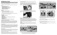
Swashplate eCCPM Set Up:Now that you’ve built your new Whiplash helicopter, you have to make the servos work together. The Whiplash is aneCCPM model, and requires a specific radio program for the servos that control the swashplate. eCCPM is a mix that isalready programmed in your transmitter, you just have to fine tune it to your Whiplash and here’s how:The very first thing you need to do is tell your radio that a 120 degree eCCPM mix must be used. All modern transmittersshould have 120 degree eCCPM built programmed from the factory. Consult the manual that came with your radio!Before you turn on your Transmitter and power up your servos, you need to make sure they are centered. With yourtransmitter and receiver powered on, put collective stick in the exact center with all three swashplate servo hornsremoved. Then put the horns on so they are 90 degrees to the linkage. This centers the servo horn on the servo andassures that there will be equal travel on either side of the servo’s center point. If you find that you cannot get the servohorn exactly at center, you have two choices. You can flip the horn 180 degrees, sometimes the splines will line upperfect, this is the preferred method. You can also use a bit of “sub-trim” to center the servo. You really want to avoidusing subtrim because it makes leveling the swashplate a little more involved.Now you need to make sure that your servos are all working together. What we mean is the three collective servos needto be plugged into the appropriate channels, i.e. the elevator (which is the servo that controls the center ball on the swash)needs to be plugged in to channel 3, the aileron and pitch servo (the ones that control the sides of the swashplate) need tobe plugged into channels 2 and 6 (it doesn’t matter which channel just either servo, into either 2 or 6 on the RX).IF you use a Futaba or Hitec transmitter, the channel assignments are a little different. For Futaba, Elevator is channel 2,Aileron is Channel 1, and Pitch is Channel is 6.Then, using the servo reverse screen, you need to make sure that the servos are doing the proper function. All the servosneed to move up (or down) when the collective stick is moved up or down (it doesn’t matter if the collective is reversed,we’ll fix that later). If it doesn’t, you need to (one at a time) reverse the channels on the servo reverse screen until all theservos move in the same direction when the collective stick is moved.Now the aileron and elevator functions need to be sorted out. When you move the right stick right and left, the swashplateshould tilt to the right and left (it doesn’t matter if it moves right when you push the stick left, we’ll fix that later). Also,when you move the right stick forwards and aft, the elevator should tilt forward or back (at this point it doesn’t matter if thefunction is reversed, proper direction will be addressed in the next step).Now that the SERVOS are all moving in together, we need to be sure that the SWASHPLATE is moving correctly for a givencommand. Pull up the Swash Mix screen. Futaba calls it “Swash AFR” There should be 3 functions and they’ll look likethis:Aileron: 60%Elevator: 60%Pitch: 60%So, if the the swashplate tilts left when you move the cyclic (right) stick TO the right, make the value of 60% for AileronNEGATIVE or -60%, and likewise for the elevator, so if the swash tilts forward when you pull the cyclic stick BACK, makethe value of 60% NEGATIVE or -60% to correct it.The swashplate should move up and down with the collective stick, and if you RAISE the collective stick, the bladesshould show POSITIVE PITCH. And if you LOWER the collective stick, the blades should show NEGATIVE pitch. IF thatfunction is reversed, again, make the value of 60%, NEGATIVE 60% or -60%.To ensure that your Whiplash is set up as precise as possible it is very important that you follow the pitch curve set upguide, and you properly level the swashplate. There are several different tools for determining if your swashplate is level.We recommend the MA3000-10 Swashplate Leveling Tool.Place the swashplate leveler on the swashplate and ensure that it is level. The collective stick should be at the centerwith zero degrees pitch on the blades. At this same time as described in the pitch curve set up guide, the swashplateshould then be in the center of its travel, and the midpoint of the pitch curve should read 50%. If the swashplate isnot level, you can use subtrim to level it, but the preferred method would be adjusting the linkages that connect theswashplate to the servos! If you find that you have to use more than a couple of clicks of subtrim on any channel, youshould put it back to zero, and adjust mechanically by adjusting the linkages to the swashplate. After the swashplate isperfectly level at center stick, you need to level it at the extreme pitch range, i.e. full positive pitch and full negative pitch.Place the Collective stick at full positive stick with the swash leveling tool attached. If the swashplate is not level, you willuse the End Point screen or Travel Adjust screen. For instance, if the swashplate tilts slightly to the right at full positivepitch, then you will need to increase the travel for the servo that controls that swashplate ball. Now put the collectivestick at full negative, repeat the same procedure with the end points. You do have to be careful that you don’t create anybinding at the extremes of the swashplate’s travel.35
Pitch Curve Set Up:It is important that you build your model to exactly the way described in this manual. Make sure all your linkage rods areexactly the length determined in the manual included with your helicopter kit.First, go to the pitch curve menu in your radio for Idle up 1, or Stunt mode 1. You’ll see numbers, a graph or both. Therewill generally be 5 points you can adjust. You’ll have to imagine the points (1,2,3,4,5) as representing points on the collectivestick, where point 1 represents full bottom stick, and 5 represents full top stick. Obviously that makes point 3center stick and that’s where we start.Ensure that point 3 on the pitch curve (center stick) to equal 50% of the swashplate’s up and down travel, meaning thein the middle of it’s available travel. So, turn on your transmitter, and receiver, flip the flight mode switch to idle-up 1 orStunt mode, and scroll to the pitch curve menu. Now place the left stick in the center.Use a pitch gauge, (we recommend the Mavrikk 3802) ensure that there is 0 degrees pitch on both rotor blades and thatthe mixing arms, and washout arms are perpendicular to the mainshaft. If any of this is untrue, you’ll need to make it so,by adjusting slightly the length of the pushrods.Now that you’ve got 0 degrees at center stick, and point 3 on the pitch curve has a value of 50% (don’t deviate here!)We can adjust the pitch at full top and bottom collective stick positions. Generally we want to have the same amount ofpitch on the bottom stick position as we do on the top stick position in idle up or stunt mode. That means positive 10degrees on top stick, and negative 10 degrees on bottom stick (some pilots are now using more pitch 12, 13 or even 14degrees, but most people find 10 degrees to be an acceptable initial setting to learn 3D flying).With the transmitter still in idle up, or stunt mode place the collective stick at the top of it’s travel, and take a reading ofthe pitch gauge and remember that number. It should be a positive pitch value and 10 degrees is a good place to start.Now place the collective stick at the full bottom of it’s travel. It should be a negative pitch value and again -10 degreesis a good place to start. If the value is not close to 10 degrees then making it so is a simple adjustment of the swashmix function in your transmitter. In this menu, “swash mix” or “swash AFR”, there are three options. Elevator, Aileron,and Pitch. Adjusting the pitch value, adjusts the total up and down travel of the swashplate. Making the number highergives you a greater pitch range, and making the number lower gives you a smaller pitch range.If you find that at full top stick, you get a negative pitch value, and at bottom stick you get a positive pitch value, youwould go back to that “swash mix” menu, and make the value the opposite, Meaning if it was 60%, make the number–60%. That will change the direction of the swash travel.Now, You’ll notice that your pitch “curve” isn’t really a curve at all, it’s a straight line. You can adjust this if you wish bychanging points 2 and 4. Right now, point 2 is 25%, and point 4 is 75%. You can change those values and it will affecthow “jumpy” or responsive the collective is. Usually leaving it a straight line is best until you really get the “feel” for 3Dflying.If you’re a beginner chances are you’ll want to fly your model around in “normal” mode. Normal mode means that at fullbottom stick the engine is at idle and the blades are not turning. You also don’t have any need for there to be negative10 degrees of pitch, usually more like -4 or degrees is best.This can easily be achieved by raising points 1 and 2. Scroll in the transmitter menu to pitch curve for normal mode,and increase point 1 from 0% to about 35%, and then you can usually inhibit point 2, so it makes a straight line frompoint 1 to point 3, which should still be 50%.The Pitch Curve for throttle should usually look real similar to stunt mode. Throttle hold is generally used for performingautorotations.36
Throttle Curve Set Up:Turn on your transmitter. Scroll to the “throttle curve” screen and notice that there are points, usually 5, and all have anassignable percentage. For example, point 1 is 0%, and point 5 is 100%. This will be the starting point for “normal”mode, and will get the model in the air. Once you have this set up in normal mode, you’ll have to fly the helicopter todetermine whether you need more or less headspeed. This is usually a good starting point for hovering.The method you set up the throttle curve for “idle up” or “stunt” mode will vary with personal preference and the modelESC you’re using. Some ESC’s have a “governor” mode, and their set up will be specific to the model ESC you’reusing.It is possible to use a simple “v” curve for throttle on an electric model. A starting point would be to make point 1,100%, mid point 65%, and point 5 100%. This way you are asking the ESC to go to full throttle at the extremes of thepitch range, and to cut throttle down to 65% when the blades have 0 degrees of pitch. To complete the set up, you’llneed a friend and an Optical Tachometer (we recommend MA3000-50 Optical Heli Tachometer) to observe the headspeed of your helicopter. Make sure to follow the rotor speed recommendations given by the manufacturer of the rotorblades you are using. If the head speed is too low, then increase the value of the mid point of the throttle curve by 5%increments until you get the head speed you desire.Choosing your power system:Outfitting your Whiplash with a power system is really easy if you follow Miniature Aircraft USA’s recommendations.A brushless electric motor KV Range approx 500-530kv suitable for use with a “.90”/700 size model, with 6mm shaftis recommended. Higher KV motors like 560KV will work, but you will have to back down on the governor mode andpossibly consider the optional 13 tooth pinion. We have had great success throughout the prototype and design phasewith the Scorpion Hand-Wound Limited Edition 4525-520KV motor and the HKIII 4035-530KV Motor.For battery power, we recommend using two, 6s 5000mah packs with at least a 25c discharge rating. It is possible touse a 12s “stick” style battery as well, but they are less common. You’ll need to prepare some type of harness to wirethe two 6s packs in “series”, which adds the voltage of the two packs together, while the capacity remains constant.Flybarless Stabilization Electronics:If you have chosen a Flybarless model, it is possible to fly your model without additional stabilization electronics,but Miniature Aircraft USA highly recommends using Flybarless Stabilization Electronics. There are several that arecommercially available, and while they all generally accomplish the same thing, they all are set up and programmeddifferently. Contact your favorite R/C helicopter retailer and/or talk to your friends to decide which one will be the bestfor you.37
0004 M4 Washer0009 M3 Washer Small0012-1 2.5mm Pem Nut0012-2 3mm Pem Nut0016-1 M4 External Serrated Lock Washer0017-2 M2.5 Hex Nut0019 M3 Lock Nut0021 M4 Lock Nut0023 M5 Nut0032 M3 Self Tapping Screw0050-1 M2.5 Set Screw0051 M3x3 Set Screw0056 M3x5 Dog-Point Set Screw0057 M4x4 Set Screw0058-3 M4x16 Set Screw0059-0 M2.5x4 Socket Bolt0059-1 M2.5x6 Socket Bolt0059-3 M2.5x10 Socket Bolt0060-1 M3x6 Socket Bolt0061 M3x8 Socket Bolt0063 M3x10 Socket Bolt0064-3 M3x6 Button Head Socket Bolt0064-4 M3x16 Button Head Socket Bolt0065 M3x12 Socket Bolt0067 M3x14 Socket Bolt0069 M3x16 Socket Bolt0071 M3x18 Socket Bolt0078 M4x12 Socket Bolt0078-3 M4x6 Socket Bolt0078-4 M4x8 Socket Bolt0082-4 M5x32 Shouldered Socket Bolt0086-1 M5x16 Flanged Socket Bolt0081 M4x16 Socket Bolt0088 M3x8 Tapered Socket Bolt0091 M3x16 Phillips Machine Bolt0107 M3x6 Threaded Steel Ball0109 M3x8 Threaded Steel Ball0112 M3x9.5 Threaded Steel Ball0116 M2.5 Threaded Steel Ball0133 M2x21.2 Ball Link0133-1 M3x21.2 Ball Link0135 M2x16.4 Ball Link0159 3x7x3 Bearing0214 Upper Swash Ring0214-1 Lower Swash Ring0215 M6 Tail Shaft Collar0216 Heim Ball0217 Swash Plate Assembled0218 20x32x7 Swash Bearing0219 Washout Center Hub0225 Link Pin0273 6x10x.011” Steel Washer0283 6x10x3 Flanged Bearing0303 Flybar0313 M2x10 Threaded Control Rod0319 8x16x5 Bearing0390 Large Wire Lead Retainer0442 T/R Pitch Link0447-1 M2 E Clip0597-1 M3x4.75x.126” Brass Spacer0597-4 Brass Spacer0840-27 Washout Head PinsWhiplash Kit Parts & Hardware0866-8 Sprag0869 Washout Link106-02 3x7x3 Flanged Bearing106-05 Metal Washout Arm106-06 2x5x1.5 Flanged Bearing106-22 5x11 Grommet120-7 5x15 C/F Safety Washer120-25 Swash To Mixer Linkage Rod120-39 5x10x4 Ball Bearing121-4 Servo To Swash Linkage Rod121-7 Swash To PA Linkage Rod122-28 Brass Spacer122-47 Upper Pinion Bearing122-48 C-Clip For Sprag122-70 M5x.25 S/S Shim Washer127-37 10x19x5 Flanged Bearing127-86 M6x9.7x1.0 Shim Washer128-57 Tray Mount128-58 Main Frame Spacer128-59 M4 Frame Spacer128-80 Front Boom Clamp128-144 T/R Control Rod Guide128-146 Boom Support End128-149a Upper Rear Boom Support Mount128-149b Lower Rear Boom Support Mount128-176 Washout Pin128-189 Cage Bar128-195 Head Button128-196 Aluminum Bell Mixer128-314 Swashplate Follower Arm129-49 9/16” Rubber Wire Grommet131-1 Main Gear 124T131-8 FB Main Shaft131-15 Tail Drive Gear131-17 Bevel Gear Shaft Side131-18 Tail Bevel Gear TT Side131-19 10x26x8 Main Shaft Bearing131-20 Middle Main Shaft Bearing Block131-21 Upper Main Shaft Bearing Block131-23 6x13x5 Flanged Bearing - Tail Shaft131-24 Main Gear Hub131-29 C/F X-Brace131-33 15x21x4 Bearing - Tail Gear131-34 Front Tail Drive Transmission131-35 Boom Clamp W/TX Holes131-40 Main Shaft Bearing Block Bottom131-46 P/A Servo Rail131-47 C/F Servo Rail Spacer131-50 Elevator Servo Mount131-51 Jack Shaft131-52 Delrin Tray Mount131-53 Gyro Plate131-54 M4 Tray Mount131-55 C/F Angled Battery Tray131-57 Torque Tube End131-58 Torque Tube131-60 C/F Tail Fin131-62 Tail Boom131-64 Tail Hub131-66 4x10 Thrust Bearings - Tail Grips131-69 2x315 Linkage Rod131-69-1 T/R Push Rod38131-70 Tail Output Shaft131-71 Tail Pitch Yoke131-72 Brass Slider131-73 7x11x3 Bearing - Control Ring131-74 Control Ring131-75 T/R Pitch Slider <strong>Assembly</strong>131-80 Delrin TT Bearing Cup131-81 TT Bearing Cup O Ring131-83 Anti Rotation Pin131-84 Boom Support Rod131-85 Carbon Pushrod Sleeve131-86 Assembled Boom Support131-107 T/R Bellcrank Swing Arm131-109 Swing Arm Pivot Mount131-112 T/R Blade Grip131-128 C/F Boom Clamp Plate131-129 Tail Box131-130 Tail Pitch Control Bellcrank131-131 C/F Tail Bellcrank Bracket131-132 Bellcrank Slider Cup131-135 Bracket Washer131-136 Strut131-139 Skid Tube131-148 Servo Plates131-150 Front Canopy Post131-151 Rear Canopy Post131-152 Whiplash Canopy131-153 C/F Breakaway Tab131-154 Thumb Screw131-155 Cage End131-157 Cross Tube131-161 Main Blade Grip131-162 FB Pitch Arm131-163 FBL Pitch Arm131-166 4x8x3 Flanged Bearing131-168 FB Head Block131-181 9x17x5 Radial Bearing131-182 9x17x5 Thrust Bearing (F9-17)131-183 9x14x.030 Washer131-184 9x14x.080 C/F Damper Washer131-186 Anti Rotation Bracket131-187 Head Axle131-190 Damper (80D)131-200 M4x33 Shouldered Socket Bolt131-201 M4x25 Shouldered Socket Bolt131-308 FBL Main Shaft131-368 FBL Head Block132-4 Sprag Cup132-14 14T Pinion132-51 C/F Whiplash Electric Frame L132-53 C/F Whiplash Electric Frame R132-57 C/F Battery Tray Electric132-58 C/F Bottom Plate- Electric132-59 C/F Front Doubler Electric132-60 C/F Rear Doubler Electric132-100 X Block/motor Mount132-101 Lower Pinion Bearing Block3200-46 1/2” Hook & Loop Tape3200-54 Adhesive Back Hook & Loop Tape3200-56 Battery Straps
WarrantyThe warranty covers defects in material or workmanship or missing components to the original purchaserfor 30 days from the date of purchase. Miniature Aircraft, USA will replace or repair, at our discretion, thedefective or missing component. Defective components MUST BE returned to us prior to replacement.Any part, which has been improperly installed, abused, crash damaged or altered by unauthorized agencies,is not covered. Under no circumstances will the buyer be entitled to consequential or incidental damages.The components used in this kit are made from special materials designed for special applications anddesign strengths. We recommend that all replacement parts be original parts manufactured by MiniatureAircraft, USA, to ensure proper and safe operation of your model. Any part used which was manufactured byany firm other than Miniature Aircraft USA, VOIDS all warranties of this product by Miniature Aircraft USA.39
miniature aircraft usa2885 Farley Lane • Billings, MT 59101, USAPhone: 1.406.245.4883Website: http://www.miniatureaircraftusa.comEmail: minair@miniatureaircraftusa.com