Engineering Company with a Passion for Technology ... - Iv-Groep
Engineering Company with a Passion for Technology ... - Iv-Groep
Engineering Company with a Passion for Technology ... - Iv-Groep

Create successful ePaper yourself
Turn your PDF publications into a flip-book with our unique Google optimized e-Paper software.
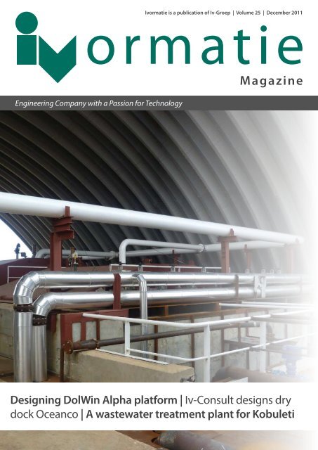
<strong>Iv</strong>ormatie is a publication of <strong>Iv</strong>-<strong>Groep</strong> | Volume 25 | December 2011<br />
ormatie<br />
magazine<br />
<strong>Engineering</strong> <strong>Company</strong> <strong>with</strong> a <strong>Passion</strong> <strong>for</strong> <strong>Technology</strong><br />
Magazine<br />
Designing DolWin Alpha plat<strong>for</strong>m | <strong>Iv</strong>-Consult designs dry<br />
dock Oceanco | A wastewater treatment plant <strong>for</strong> Kobuleti
Excavation Panama Canal<br />
Challenges<br />
It is Tuesday 15 November. I am in Panama to discuss a few ongoing matters <strong>with</strong> the client. As readers will<br />
probably know, we are currently designing the new Panama Canal lock gates. This is an enormous project, and as<br />
in all enormous projects there can occur some enormous problems. Perhaps it would be better to describe them<br />
as ‘challenges’.<br />
But there are no problems or challenges today. I am on site, standing at the bottom of a deep trench through<br />
which the new, extended canal will flow in just a few years. It is some fifty metres deep and at least 100 metres<br />
wide. It is difficult to estimate the length: this is, after all, a canal. It is easy to spot where the new lock gates will be<br />
located, since the excavations are much wider at this point. Standing here, one feels very insignificant. It is a very<br />
special feeling.<br />
They are currently pouring the concrete. At present, some 20,000 m 3 is mixed and poured every month, but the<br />
volume will be increased to 120,000 m 3 a month. And that is just <strong>for</strong> one complex: the same volume will be<br />
required on the other side of the canal. These are enormous quantities which are almost beyond comprehension.<br />
According to my maths, 120,000 m 3 a month is the equivalent of twelve thousand truckloads: four hundred a day,<br />
<strong>for</strong>ty an hour. Almost one truck a minute, every minute.<br />
These enormous quantities are produced at a new purpose-built plant where rocks are broken up and the debris<br />
mixed <strong>with</strong> sand, cement and water. Some water is added in the <strong>for</strong>m of ice: <strong>for</strong> cooling, it would otherwise become<br />
far too hot. My calculation overlooks one salient point: there are no trucks. The concrete is actually transported to<br />
wherever it is needed on enormous conveyor belts.<br />
What an undertaking! And just think: when the canal was originally dug over a hundred years ago, none of this<br />
hi-tech machinery had been invented. Everything had to be done by hand or <strong>with</strong> very rudimentary machines.<br />
Excavating this much soil <strong>with</strong> just a shovel and small digging machines just doesn’t bear thinking about. It were<br />
the French who first attempted to construct a canal to link the Pacific and Atlantic oceans. That project began<br />
in 1880, but was abandoned after over 20,000 workers had died, mostly from malaria and yellow fever. In 1904,<br />
the United States launched a second ef<strong>for</strong>t. Despite a further 5,600 deaths, the gates of the Panama Canal were<br />
officially opened on 15 August 1914. Their replacements must be ready precisely one hundred years later.<br />
Rob van de Waal<br />
Managing Director <strong>Iv</strong>-<strong>Groep</strong><br />
I realize that I am standing on a location <strong>with</strong> a truly remarkable history. What an honour it is<br />
to work on a project like this. And the ‘challenges’? They’re all in a day’s work!<br />
2 IVORMATIE MAGAZINE DECEMBER 2011<br />
December 2011, Volume 25, Number 5<br />
Editorial staff<br />
<strong>Iv</strong>-<strong>Groep</strong>, Marketing & Communication<br />
department<br />
<strong>Iv</strong>ormatie<br />
A publication of <strong>Iv</strong>-<strong>Groep</strong>:<br />
<strong>Iv</strong>-Oil & Gas<br />
<strong>Iv</strong>-Infra<br />
<strong>Iv</strong>-Industrie<br />
<strong>Iv</strong>-Consult<br />
<strong>Iv</strong>-Water<br />
<strong>Iv</strong>-Bouw<br />
Escher Process Modules<br />
<strong>Iv</strong>-Software<br />
Muzada<br />
<strong>Iv</strong>-AGA<br />
<strong>Iv</strong>-Consult Sdn. Bhd.<br />
<strong>Iv</strong>-Caribbean<br />
Nevesbu<br />
Editorial office<br />
<strong>Iv</strong>-<strong>Groep</strong> b.v.<br />
P.O. Box 1155<br />
3350 CD Papendrecht<br />
mail@iv-groep.nl<br />
www.iv-groep.com<br />
Copyright © 2011 <strong>Iv</strong>-<strong>Groep</strong>. All rights reserved.<br />
Reproduction in whole or in part requires written<br />
permission.<br />
Cover: Buska Bay asphalt lake on Curaçao
Content<br />
4<br />
6<br />
8<br />
12<br />
14<br />
18<br />
22<br />
24<br />
28<br />
30<br />
Winksele compressor project<br />
A completely new H-Gas compression station at Winksele, Belgium<br />
BP Chirag Oil Project<br />
ESCHER focusses on Caspian Sea<br />
Transporting Wind Energy<br />
Designing the DolWin Alpha plat<strong>for</strong>m<br />
The IJsselmeer area<br />
Condition assessment and maintenance scheduling inspections in the largest<br />
lake district in the Netherlands<br />
Building a wastewater treatment plant <strong>for</strong> Kobuleti<br />
Improving the water supply and effluent treatment<br />
Oceanco new-build<br />
<strong>Iv</strong>-Consult designs dry dock<br />
Integration of free cooling into an existing operational situation<br />
<strong>Iv</strong>-Industrie delivers engineering services <strong>for</strong> India's 'largest<br />
blast furnace'<br />
Cleaning up Buska Bay asphalt lake on Curaçao<br />
A relatively simple solution to a major environmental problem<br />
Early attention to risk and safety management offers extra<br />
oppurtunities<br />
ormatie<br />
3
Winksele compressor project<br />
A completely new H-Gas compression<br />
station at Winksele, Belgium<br />
In June 2010 Joint Venture Winksele (JVW), a cooperation between Visser & Smit Hanab and<br />
<strong>Iv</strong>-Oil & Gas, was awarded an EPC contract by Fluxys NV at Brussels <strong>for</strong> the design, construction and<br />
installation of a completely new H-Gas compressor station. The project comprises the <strong>Engineering</strong>,<br />
Procurement and Construction (EPC) of the station, including the Completion and Commissioning.<br />
The project will be carried out at Winksele in Belgium. In the 2010 December edition of the <strong>Iv</strong>ormatie<br />
magazine we already in<strong>for</strong>med you about this project, now the construction work is in full swing.<br />
4 IVORMATIE MAGAZINE DECEMBER 2011
Het compressiestation bestaat uit vier nieuwe compressoren samen<br />
met de vereiste bijpassende installaties, constructie en civiel werk.<br />
Dit zorgt voor een compressiecapaciteit van maximaal 3.500.000<br />
Nm³/h. Iedere compressor heeft een vermogen van 18 MW en<br />
is elektrisch aangedreven met variabele regeling. De installaties<br />
bestaan verder onder andere uit filters, koelers, trans<strong>for</strong>matoren,<br />
controle systemen en vereiste ondersteunende voorzieningen. De<br />
constructie activiteiten bevatten de bouw van de gebouwen, de<br />
omheiningen, de fabricage en installatie van de nieuwe installaties<br />
en pijpleidingen, de complete elektrische installatie vanaf 150 kV en<br />
een afblaastoren.<br />
Joint Venture Winksele<br />
Visser & Smit Hanab and <strong>Iv</strong>-Oil & Gas, Joint Venture Winksele, are<br />
fully responsible <strong>for</strong> the project as a whole. <strong>Iv</strong>-Oil & Gas is designing<br />
the entire gas compressor station and is handling procurement.<br />
Visser & Smit Hanab is responsible <strong>for</strong> the mechanical side of the<br />
construction work. All other work is being carried out by the Joint<br />
Venture.<br />
Project<br />
Starting its design and engineering work in July 2010, <strong>Iv</strong>-Oil & Gas<br />
subsequently began purchasing all equipment, pipes, instruments<br />
and electrical components. At the end of January 2011, JVW<br />
received permission to prepare the site facilities <strong>for</strong> construction<br />
work. It was possible to cordon off the temporary site after<br />
confirmation of the first permit. The site was hardened <strong>with</strong> gravel<br />
to enable the beginning of constructing the project office. Because<br />
the new compressor station is being built alongside an existing<br />
station, five incoming and outgoing gas pipelines are already in<br />
the ground. These pipes were localised and marked <strong>with</strong> concrete<br />
tiles to avoid heavy vehicles to drive over them. To protect the<br />
underground pipes, crossover protections were created at places<br />
where JVW must cross the existing pipelines. Our customer Fluxys<br />
has also moved into the project office to oversee the project in<br />
terms of progress, quality standards and safety onsite.<br />
Oil & Gas<br />
The civil engineering work began by excavating the site at<br />
the location of the trans<strong>for</strong>mer building, the extinguishing<br />
water reservoir and the substation. Then a temporary road was<br />
constructed and the road along the compressor station was<br />
broadened. After the foundations of the other buildings had been<br />
excavated, the temporary floors and the rein<strong>for</strong>cement could be<br />
realised. Two tower cranes were used to ensure that the different<br />
types of work could be carried out in rapid succession. One crane<br />
was used <strong>for</strong> the trans<strong>for</strong>mer building and substation, while the<br />
other was used <strong>for</strong> the compressor and VSD buildings.<br />
In April 2011 the first fittings and piping materials arrived at piping<br />
pre-fabricator Visser & Smit Hanab at Veendam (the Netherlands)<br />
and onsite in Winksele. The Fluxys specifications were used<br />
to compile welding procedures and these were subsequently<br />
submitted to Fluxys <strong>for</strong> approval. The welding work was started<br />
after all the material certificates had been checked, the welding<br />
procedures had been approved and a pre-inspection meeting had<br />
been held <strong>with</strong> Fluxys. The made to measure pipe sections were<br />
installed underground and in the buildings. The first machines and<br />
150 kV trans<strong>for</strong>mers have been installed and the compressors and<br />
filters will follow in the coming months. The project is contractually<br />
scheduled <strong>for</strong> completion in September 2012.<br />
Michel Bosman,<br />
Manager of Projects, <strong>Iv</strong>-Oil & Gas<br />
5
BP Chirag Oil Project<br />
ESCHER focusses on Caspian Sea<br />
Escher Process Modules (ESCHER) secured a prestigious order from BP at the beginning<br />
of last year <strong>for</strong> the design and delivery of a gas dryer installation consisting of a glycol<br />
contactor, gas scrubber, glycol regeneration unit and hoisting equipment. The gas<br />
dryer is part of the BP Chirag Oil Project in the Caspian Sea. It was shipped out from the<br />
Netherlands to Azerbaijan at the end of August 2011. In October this feat of engineering<br />
was put in its final place on the offshore plat<strong>for</strong>m. Vincent Rüter, deputy director of<br />
ESCHER, explains how the project has progressed and outlines the next steps.<br />
6 IVORMATIE MAGAZINE DECEMBER 2011
BP has five offshore plat<strong>for</strong>ms in the Caspian Sea <strong>for</strong> the<br />
development of the Azeri-Chirag Deepwater Gunashli (ACG) field,<br />
which started in 1994. The field is now completely operational<br />
and BP is using the five plat<strong>for</strong>ms to produce oil and export it via a<br />
large terminal at a rate of 1.2 million barrels a day. BP has invested<br />
another six billion dollars in an additional plat<strong>for</strong>m – the Chirag Oil<br />
Project – that will be operational by year-end 2013. BP approached<br />
ESCHER in autumn 2009 and requested a design <strong>for</strong> a gas dryer<br />
installation needed on the new offshore production plat<strong>for</strong>m <strong>for</strong> the<br />
Chirag Project.<br />
ESCHER and BP had previously cooperated <strong>with</strong> each other<br />
several times. But on this occasion it was not just about a new<br />
design <strong>with</strong> important safety aspects, but also about a state-ofthe-art<br />
end-product. ESCHER is doing more than just the design,<br />
emphasises Rüter, it is also responsible <strong>for</strong> the execution of the<br />
design, manufacturing, testing and transport. At the beginning of<br />
last year BP and ESCHER conducted negotiations <strong>for</strong> the gas dryer<br />
installation. This is a major project <strong>for</strong> ESCHER which was discussed<br />
thoroughly. The design and proposal were subsequently tailored<br />
to fit the project and in March 2010 ESCHER received from BP the<br />
contract to design, build, certify and deliver the new installation.<br />
The gas dryer installation extracts water and hydrocarbons from<br />
the gas. The gas mixture runs through two large drums. The first<br />
drum removes the free water and the second absorbs most of the<br />
residual water and hydrocarbons by means of the added glycol.<br />
The ‘dry’ gas then passes through the outlet. A regeneration unit is<br />
used to cleanse the glycol of some of the water and hydrocarbons<br />
<strong>for</strong> reuse in combination <strong>with</strong> freshly added glycol. The exact inlet<br />
specifications and, even more important, the outlet specifications<br />
were laid down contractually.<br />
Vincent Rüter is enthusiastic about the innovative nature of the<br />
design. He says: “What we’ve developed <strong>for</strong> this client is also usable<br />
in other fields. For example CO drying, because it involves the same<br />
²<br />
aspects. The lessons learnt from previous projects were examined<br />
critically during the design work, because ease of maintenance,<br />
accessibility and safe operation of the installation were key aspects.<br />
When it comes to these subjects you can learn time and again from<br />
earlier projects or recently gained experience.”<br />
Oil & Gas<br />
“Besides the lessons learnt, the dimensions and weights of the<br />
entire installation required extra attention, because of its use<br />
offshore, the need <strong>for</strong> hoisting, the safety requirements and because<br />
the installation has to fit into the limited space available on the<br />
drilling plat<strong>for</strong>m. Optimisation and efficiency are very important.”<br />
To design the installation ESCHER cooperated intensively <strong>with</strong><br />
various specialists available in-house at parent company <strong>Iv</strong>-<strong>Groep</strong>.<br />
They included professionals at <strong>Iv</strong>-Oil & Gas, <strong>Iv</strong>-Consult and<br />
<strong>Iv</strong>-Industrie. “That is the real strength of our organisation and also<br />
part of the added value we offer our clients,” says Rüter.<br />
On completion of the drawings and calculations, ESCHER in its<br />
role of main contractor engaged various qualified subcontractors<br />
and suppliers <strong>for</strong> the required components and activities. For the<br />
manufacturing of the installation the leading role in this project<br />
went to Hollandia Systems of Heijningen (the Netherlands), where<br />
the skid-mounted unit was ultimately constructed under ESCHER’s<br />
responsibility and supervision. ESCHER cooperates regularly <strong>with</strong><br />
this company on account of its considerable know-how <strong>with</strong>in the<br />
offshore, chemical and process industries. All in all it took six months<br />
to complete the manufacture and assembly of the piping. In early<br />
August the installation underwent a thorough Factory Acceptance<br />
Test (FAT) in consultation <strong>with</strong> the client. This was followed by<br />
fine-tuning, after which the structure was shipped to the Caspian<br />
Sea towards the end of August to be lifted on to the plat<strong>for</strong>m in<br />
October. The next step will be to connect the installation to the rest<br />
of the oil plat<strong>for</strong>m of which it will be an integral part. Vincent Rüter<br />
expects the internals to be installed in the drums in spring 2012. He<br />
does not expect the installation to be commissioned be<strong>for</strong>e yearend<br />
2012. For that process ESCHER will provide various specialists<br />
to work alongside the client on the plat<strong>for</strong>m <strong>for</strong> the commissioning<br />
of the entire installation. After commissioning the climax will be<br />
the Site Acceptance Test (SAT), which involves demonstrating that<br />
everything is working properly and that all defined specifications<br />
have been met. “We will obviously remain responsible <strong>for</strong> the<br />
project all the way to the end of the warranty period in 2014,” says<br />
Rüter.<br />
Vincent Rüter<br />
Deputy director, Escher Process Modules<br />
7
Transporting Wind Energy<br />
Designing the DolWin Alpha Plat<strong>for</strong>m<br />
Multiple offshore HVDC (High Voltage Direct Current) trans<strong>for</strong>mer substations are being built at<br />
about 60 km off the German coast in the North Sea. These substations are used to convert electric<br />
power from Alternating Current (AC) to Direct Current (DC) in order to interconnect offshore<br />
wind farms to the German power grid. TenneT Offshore GmbH is the Electrical Grid Controller<br />
of the substations and the customer <strong>for</strong> the design, manufacturing and installation of the HVDC<br />
trans<strong>for</strong>mer plat<strong>for</strong>ms.<br />
8 IVORMATIE MAGAZINE DECEMBER 2011
Location of DolWin Alpha<br />
DolWin Alpha<br />
Netherlands<br />
DolWin Alpha is one of these HVDC trans<strong>for</strong>mer plat<strong>for</strong>ms.<br />
ABB Offshore Wind Connections is the main contractor <strong>for</strong> the<br />
entire project. The project consists of the DolWin Alpha offshore<br />
trans<strong>for</strong>mer plat<strong>for</strong>m, an onshore trans<strong>for</strong>mer substation at Dörpen<br />
(Germany) to make the connection <strong>with</strong> the German electricity grid<br />
and all the interconnecting onshore and offshore cables.<br />
Heerema Fabrication Group in Zwijndrecht (the Netherlands) was<br />
contracted by ABB to design and build the plat<strong>for</strong>m including its<br />
plat<strong>for</strong>m support facilities and they asked <strong>Iv</strong>-Oil & Gas to per<strong>for</strong>m<br />
the design.<br />
Germany<br />
Oil & Gas<br />
Offshore wind farm<br />
Energy is increasingly generated from wind farms offshore, because<br />
of the great potential of the wind offshore. A growing number of<br />
offshore wind turbine farms are being developed.<br />
The energy, generated by a wind farm, is gathered at 155 kV<br />
Substations. From these substations, the energy is transmitted by<br />
Subsea cable to an HVDC Trans<strong>for</strong>mer Transmission Plat<strong>for</strong>m.<br />
Here, the energy will be converted from high-voltage alternating<br />
current (155kV AC) to direct current (320kV DC) and transported<br />
onwards to shore. Because of large throughput and the long<br />
distance to the shore, it is proven to be more economical to<br />
transport the electricity by direct current than by alternating<br />
current, as it reduces the energy losses caused by heat dissipation.<br />
9
Dimensions of the DolWin Alpha plat<strong>for</strong>m, seen from the front and side<br />
DolWin Alpha plat<strong>for</strong>m<br />
The DolWin Alpha plat<strong>for</strong>m houses an 800 MW HVDC trans<strong>for</strong>mer<br />
substation. This substation receives electrical energy from<br />
the nearby wind farm substations, each supporting blocks of<br />
approximately 80 wind turbines, using relatively short distance<br />
subsea cables at 155 kV 3-phase AC. At the HVDC substation, the<br />
alternating current is converted to 320 kV direct current to be able<br />
to transport the electricity to the onshore receiving substation.<br />
Flowchart<br />
8 metres<br />
20.8 metres<br />
10 IVORMATIE MAGAZINE DECEMBER 2011<br />
62 metres 43.3 metres<br />
24 metres<br />
9.5 metres<br />
21 metres 36 metres<br />
27 metres<br />
41.68 metres<br />
The HVDC transmission plat<strong>for</strong>ms are grouped together at sea to<br />
be able to expand the HVDC system easily, reducing the operating<br />
costs. By installing bridges between the plat<strong>for</strong>ms, one of them,<br />
normally the first one, will be used as mother plat<strong>for</strong>m. The mother<br />
plat<strong>for</strong>m houses all the central facilities, such as the living quarters<br />
and a helicopter deck. DolWin Alpha will act as a mother plat<strong>for</strong>m.
The key components of the trans<strong>for</strong>mer plat<strong>for</strong>m are a 155 kV Gas<br />
Insulated Switchgear (GIS) <strong>for</strong> connecting the AC cables to the wind<br />
farm, main trans<strong>for</strong>mers of 155 kV/320 kV and a 400 kV rated GIS<br />
<strong>for</strong> linking and protecting the main step-up trans<strong>for</strong>mers. Other<br />
components are also necessary, as the flowchart on the previous<br />
page shows.<br />
The DolWin Alpha plat<strong>for</strong>m consists of a jacket <strong>with</strong> a large topside.<br />
The jacket comprises a conventional support structure <strong>with</strong> six<br />
legs, which has a footprint of approximately 24 x 26.4 metres. The<br />
legs are supported by six foundation piles driven approximately<br />
55 metres into the bottom of the sea. At the plat<strong>for</strong>m location, the<br />
water depth is approximately 27 metres. The jacket further supports<br />
the 12 ‘J tubes’ (used to pull and guide the electricity cables on to<br />
the plat<strong>for</strong>m) and four caissons to protect the sea water pumps,<br />
used <strong>for</strong> the cooling system.<br />
The topside measures approximately 62 x 43.3 x 36 metres,<br />
excluding the helicopter deck. The total weight of the plat<strong>for</strong>m<br />
as a whole is 17,500 tonnes, <strong>with</strong> the topside accounting <strong>for</strong><br />
11,000 tonnes, the jacket 4,000 tonnes and the six piles jointly<br />
approximately 2,500 tonnes.<br />
Windfarm<br />
Substation<br />
plat<strong>for</strong>m<br />
33/150 kV<br />
Trans<strong>for</strong>mer<br />
plat<strong>for</strong>m<br />
O�shore<br />
Distance and power<br />
determine AC or DC<br />
energy transfer<br />
155 kV Ac kV320 kV Dc<br />
155/375 kV Ac 320 kV Dc<br />
Input from other substation plat<strong>for</strong>m<br />
Transmitting large volumes of energy over large distances results in large losses in the transmission cables<br />
There is a tipping point at which it becomes more economical to transmit the energy by means of direct current instead of alternating current<br />
Requirements<br />
The plat<strong>for</strong>m design satisfies the requirements laid down by the<br />
German Authority <strong>for</strong> offshore installations, BSH (Bundesamt für<br />
Schiffe und Hydrography), while the design calculations and safety<br />
facilities are being reviewed and verified by the independent<br />
classification society DNV (Det Norske Veritas). The plat<strong>for</strong>m,<br />
including all equipment, was designed according<br />
to the regulations. The emphasis was on availability of the power<br />
transmission system, the reliability, low maintenance and easy<br />
servicing and repairs.<br />
The plat<strong>for</strong>m and all its supporting systems have a minimum service<br />
life of 30 years and have been designed <strong>with</strong> a view on minimizing<br />
the total cost of ownership, based on operational and maintenance<br />
costs. Suppliers are required to guarantee the availability of spare<br />
parts and technical support <strong>for</strong> the plat<strong>for</strong>m’s entire service life.<br />
=<br />
Onshore<br />
DC Link<br />
Trans<strong>for</strong>mer<br />
plat<strong>for</strong>m<br />
=<br />
Oil & Gas<br />
Electricity<br />
grid<br />
Wim van der Horst<br />
Project Manager, <strong>Iv</strong>-Oil & Gas<br />
11
The IJsselmeer area<br />
Condition assessment and maintenance<br />
scheduling inspections in the largest lake<br />
district in the Netherlands<br />
The Directorate-General <strong>for</strong> Public Works and Water Management (‘RWS’) is a Dutch<br />
government agency <strong>with</strong> a department that is responsible <strong>for</strong> the area in and around the<br />
IJsselmeer, an artificial lake in the centre of the country. The department’s tasks include<br />
managing four primary flood defences and constituent assets such as hydraulic structures<br />
like locks and sluices. The catchment area embraces the Afsluitdijk causeway and the<br />
Houtribdijk dike that protect the important IJsselmeer and Markermeer freshwater basins.<br />
RWS also manages waterways in the IJsselmeer, Markermeer and peripheral lakes around<br />
Flevoland and various adjacent banks, harbours and mooring facilities.<br />
12 IVORMATIE MAGAZINE DECEMBER 2011
Scope<br />
RWS put out an inspection contract to obtain a good picture<br />
of the current situation throughout this area and of the likely<br />
maintenance costs over the coming fifteen years. The contract went<br />
to the combination Advin/<strong>Iv</strong>-Infra/Tauw. The Management and<br />
Maintenance and Waterways sectors of <strong>Iv</strong>-Infra carried out the work.<br />
Inspections<br />
The inspections were per<strong>for</strong>med from land and on water. A new<br />
vessel was used <strong>for</strong> the waterborne inspections. The vessel is usable<br />
<strong>for</strong> inspections in all coastal and inland waters. The small height<br />
of the vessel makes it ideal <strong>for</strong> inspections around the waterline. It<br />
makes it possible to obtain from the right perspective a snapshot of<br />
the degradation of bank protection and structures caused by wave<br />
attacks or corrosive conditions.<br />
Waterborne inspection in the harbour of Den Oever<br />
Reproduction<br />
The observations made at these large assets were recorded by<br />
GPS to ensure the reproducibility of the inspection results. The<br />
data of the GPS loggers was linked to photographs taken during<br />
the inspection. The advantage of this approach is that photo<br />
overviews are viewable by means of readily accessible software. The<br />
photographs were put on to the map in the right locations.<br />
Lorentz sluices at Kornwerderzand<br />
Infrastructure & Ports<br />
Condition assessment according to NEN 2767-4<br />
The present condition of RWS’s IJsselmeer area was recorded in<br />
con<strong>for</strong>mity <strong>with</strong> the new NEN 2767-4 standard <strong>for</strong> assessing the<br />
condition of infrastructure. The standard prescribes a method<br />
<strong>for</strong> uni<strong>for</strong>mly describing assets and the defects and deficiencies<br />
observed on them. Application of this method produces a condition<br />
score that indicates the state of the different parts of an asset and<br />
the expected residual life.<br />
Risk management<br />
The condition assessments were supplemented by a risk-based<br />
prioritization and long-term maintenance scheduling inspection.<br />
The data was entered in the database of the <strong>Iv</strong>-Beheerprogramma<br />
(Management Program). This is a program that provides a clear,<br />
uni<strong>for</strong>m and transparent report on each asset. The generated<br />
maintenance schedule also clearly shows the costs of each<br />
asset. One of the key advantages is the establishment of a clear<br />
relationship between the observed defects, the risk analysis and<br />
the repair recommendations. The repair recommendations are<br />
subsequently re-included in the risk analysis to assess their effect.<br />
Risks that cannot be reduced to an acceptable level after targeted<br />
measures will thus remain visible.<br />
The entire RWS IJsselmeer catchment was mapped in this way to<br />
give RWS in its role as the infrastructure manager an unambiguous<br />
picture of the prevailing condition of the assets, the risks and<br />
the maintenance costs. This provides the manager <strong>with</strong> accurate<br />
in<strong>for</strong>mation <strong>for</strong> managing, maintaining or commissioning the<br />
maintenance of its catchment area.<br />
Bas de Ruiter<br />
Advisor Asset Management, <strong>Iv</strong>-Infra<br />
13
Building a wastewater treatment plant<br />
<strong>for</strong> Kobuleti<br />
Improving the water supply and effluent<br />
treatment<br />
Kobuleti is situated on Georgia’s Black Sea coast, 35 km from the regional capital of Batumi. The<br />
town has always attracted tourists and has great potential <strong>for</strong> becoming Georgia's principal<br />
tourism centre. Tourism is one of the key pillars of economic growth in Georgia, so the country's<br />
central government decided, in consultation <strong>with</strong> the regional government, to press ahead on<br />
developing Kobuleti. They have given high priority to developing the town's infrastructure by<br />
improving the water supply and effluent treatment. The objective is to improve the standard of<br />
living <strong>for</strong> the local population and tourists. The European Union regards pollution in the Black Sea<br />
as the region’s main problem and is subsidising the project.<br />
Settlement tank <strong>with</strong> a chain-and-flight collecting mechanism<br />
14 IVORMATIE MAGAZINE DECEMBER 2011
These are the circumstances under which Orange Water Solutions<br />
(part of Visser & Smit Hanab) was contracted to design and build<br />
a water treatment plant <strong>for</strong> the Kobuleti region. To carry out this<br />
contract Visser & Smit Hanab asked <strong>Iv</strong>-Water to contribute its<br />
specific knowledge of treating effluent and building wastewater<br />
treatment plants.<br />
Project<br />
The objective of this project is to use simple and proven technology<br />
to design an economically sound and maintenance-friendly plant.<br />
The design of the wastewater treatment plant can be divided into<br />
four disciplines:<br />
• process technology: design the process from effluent to 'clean'<br />
water;<br />
• mechanical engineering: design and produce specifications <strong>for</strong><br />
all mechanical engineering installations and process pipelines;<br />
• electrical & instrumentation engineering and process<br />
automation: design all electrical systems and the automation of<br />
the wastewater treatment plant;<br />
• architectural design: design all architectural elements, including<br />
the building itself and the concrete tanks complete <strong>with</strong> their<br />
foundations.<br />
Cross-section of a settlement tank <strong>with</strong> a chain-and-flight collecting mechanism<br />
Water<br />
The design of this project presented the challenge of dealing <strong>with</strong><br />
greatly fluctuating seasonal loads. An explosive growth in the<br />
number of residents in the tourist season means a far greater supply<br />
of sewage at this time of the year, than in the other seasons. So<br />
the wastewater treatment plant has to be sized to handle the load<br />
in both periods. Another challenge was the short time available<br />
<strong>for</strong> preparing the design. Everything had to be ready <strong>with</strong>in three<br />
months.<br />
<strong>Engineering</strong> of a wastewater treatment plant <strong>with</strong> an active<br />
sludge system<br />
The process at the Kobuleti wastewater treatment plant involves<br />
biological treatment using an 'active sludge system'. A variety of<br />
bacteria grow in this system. The types of bacteria partly depends<br />
on the inbound effluent. It is necessary to bring the bacteria to a<br />
state where the right bacteria will grow and survive so as to achieve<br />
the targeted level of treatment.<br />
15
The Kobuleti wastewater treatment plant consists of a selector,<br />
an aeration tank, settlement tanks, sludge thickener and sludge<br />
storage.<br />
The Selector<br />
A selector is needed to obtain active sludge <strong>with</strong> good settlement<br />
properties. Two kinds of bacteria grow in a biological treatment<br />
plant. They are bacteria that grow as flakes and bacteria that grow<br />
as strings. The strings interfere <strong>with</strong> the separation process in the<br />
settlement tank. There<strong>for</strong>e, the selector 'selects' the bacteria that<br />
grow as flakes from the other bacteria. The result is a lower Sludge<br />
Volume Index (SVI) and, consequently, a better separation process.<br />
Aeration tank<br />
The aeration tank is where the biological treatment actually occurs.<br />
The water is twirled around in a carousel in the aeration tank while<br />
oxygen is added. See the accompanying photograph of an aeration<br />
tank in Antwerp (figure 1). Oxygen is added by means of a surface<br />
aerator. Figure 2 shows a surface aerator. Various processes occur<br />
due to the changing conditions in aerated and non-aerated zones.<br />
Figure 1 An aeration tank in Antwerp<br />
Figure 2 A surface aerator<br />
16 IVORMATIE MAGAZINE DECEMBER 2011<br />
Settlement tanks<br />
Sludge is separated from effluent in settlement tanks by allowing<br />
the sludge to settle on the bottom. Specifically <strong>for</strong> the Kobuleti<br />
wastewater treatment plant, it was decided to use rectangular<br />
settlement tanks. The sludge is scraped from the bottom by a chainand-flight<br />
collecting mechanism into the collector from where it<br />
is pumped away. Given the great load differences between the<br />
different seasons, it was decided to build several settlement tanks<br />
alongside each other. All will be used in the tourist season. In the<br />
other seasons it will be possible to suffice <strong>with</strong> only one settlement<br />
tank.<br />
Sludge thickener<br />
The sludge is thickened in the sludge thickener to reduce its water<br />
content. This makes it cheaper to dispose of the sludge.<br />
Sludge storage<br />
The thickened sludge goes to the sludge storage from where it can<br />
be pumped into lorries <strong>for</strong> outward shipment.<br />
Status update<br />
The design has been submitted to the client in Georgia <strong>for</strong><br />
evaluation. Over the coming year a civil engineering contractor will<br />
be sought in Georgia to start building the foundations and concrete<br />
structures. All equipment and all systems will be purchased in the<br />
Netherlands and shipped to Kobuleti (this is a requirement of the<br />
organisation providing the subsidy). The initial construction work is<br />
expected to start in 2012, <strong>with</strong> delivery of the wastewater treatment<br />
plant scheduled <strong>for</strong> 2013.<br />
Marcel Krullaars<br />
Project Manager, <strong>Iv</strong>-Infra
Water<br />
17
Oceanco new-build<br />
<strong>Iv</strong>-Consult designs dry dock<br />
A customer <strong>with</strong> a vision came up <strong>with</strong> these terms of reference: “Give us a functional building<br />
that looks like a showroom and has a museum-like climate to enable us to take the next step in<br />
building luxury yachts, the step from 100 to 140 metre-plus yachts.”<br />
The customer’s wish<br />
Alblasserdam Yachtbuilding Properties b.v. (AYP) develops, builds<br />
and sells highly exclusive and innovative super-yachts under its<br />
Oceanco brand. To fulfil its ambition – to build super-yachts <strong>with</strong><br />
lengths up to approximately 140 metres – the company decided in<br />
2010, after years of deliberation, to develop a covered dry dock. The<br />
complex must be built on the Zuiderstek 30 site, the <strong>for</strong>mer<br />
Giessen-De Noord yard, in Alblasserdam (the Netherlands).<br />
Construction work is due to start mid-April 2012 and delivery is<br />
scheduled <strong>for</strong> mid 2014.<br />
18 IVORMATIE MAGAZINE DECEMBER 2011<br />
The work of designing the complex has been divided into two parts.<br />
Roughly speaking they are the superstructure and the substructure.<br />
<strong>Iv</strong>-Consult is responsible <strong>for</strong> the substructure. This comprises the dry<br />
dock <strong>with</strong> its foundations, the main dock door and an intermediate<br />
door. There are now also twelve contracts <strong>for</strong> extra work, including<br />
demolition and modification of a jetty, expansion of a retaining wall,<br />
design of a swivelling crane gantry and a launching facility.
Location<br />
The site at Zuiderstek 30 is the <strong>for</strong>mer Giessen-De Noord shipyard.<br />
AYP is already using the northern side of the site. The company<br />
builds yacht hulls <strong>with</strong> lengths of up to 80 metres in the existing<br />
factory <strong>with</strong> workshops and offices. This work occurs at ground<br />
level. The yachts are transported between the water and the<br />
factory by means of an on-site ship lift and self-propelled modular<br />
transporters.<br />
Transport of Y703 to the ship lift<br />
On the southern side there were until recently still some old<br />
buildings belonging to the <strong>for</strong>mer Giessen-De Noord yard. All have<br />
now been removed and stripped to their foundations. There are still<br />
numerous obstacles in the subsoil and also some minor pollution.<br />
The obstacles must be removed and the soil must be remediated<br />
be<strong>for</strong>e construction can get underway in 2012.<br />
Yacht building process<br />
The business process consists of building and finishing the<br />
complete interior and exterior of yachts. The bare hulls are made<br />
elsewhere in Europe and brought to Alblasserdam either complete<br />
or in parts. The yachts are finished to a very high standard, <strong>for</strong><br />
example the high-gloss lacquer. The working areas must have<br />
excellent air conditioning to spray on the paint and to assure the<br />
quality of the end-product. One of the requirements that this<br />
imposes is the fitting of insulation and floor/wall heating in the<br />
concrete dock. The dock door must also be insulated. This will be<br />
accomplished by installing a separate insulated wall in front of the<br />
door.<br />
Dock<br />
The dock consists of a segmented concrete slab resting on combipiles.<br />
The outside of the dock is approximately 168 metres long, 38<br />
metres wide and 12.5 metres high. The wall thickness varies from<br />
0.6 to 2 metres and the floor is 2 metres thick. The dock incorporates<br />
a variety of standard facilities such as climb-out ladders, mooring<br />
rings, sump pits and similar. An exceptional facility is the floor and<br />
wall heating. It consists of 16 pipeline loops in each dock segment<br />
about 300 mm below the surface. They ensure a constant surface<br />
temperature of approximately 20°C. <strong>Iv</strong>-Bouw was engaged <strong>for</strong> this<br />
part of the design.<br />
Floor and wall heating<br />
Longitudinal view of the dock<br />
Cross-sectional view of the dock<br />
Building & Structures<br />
19
Main dock door<br />
After studying several variants it was decided in consultation <strong>with</strong><br />
AYP to equip the dock <strong>with</strong> a self-floating trapezoidal door. The<br />
main dock door is double-turning. The door must be able to cope<br />
<strong>with</strong> a water level difference of 10.5 metres when resisting water<br />
on one side. It must also be able to resist water on both sides when<br />
there is a river water difference of approximately 3.5 metres. The<br />
door must float up approximately 2 metres in order to position it in<br />
The door is equipped <strong>with</strong> trim and float tanks. The dock is filled and emptied by means of pumps<br />
connected to the piping on the doors.<br />
Top of the door <strong>with</strong> piping and facilities <strong>for</strong> filling and emptying.<br />
20 IVORMATIE MAGAZINE DECEMBER 2011<br />
Sealing of the door.<br />
Intermediate door<br />
AYP wants to be able to house several yachts of different lengths<br />
in the dock. This is possible by creating an intermediate door that<br />
can be installed at different predefined locations in the dock. This is<br />
a simple sloping-segment door. Six segments placed against each<br />
other <strong>for</strong>m a closed seal.<br />
Swivelling crane gantry<br />
Based on the zoning plan, the amenities committee specified the<br />
lines of sight and contours of the new building. It is not permitted to<br />
affix to the exterior any appurtenances, structures or similar, other<br />
than those agreed in the zoning plan.<br />
As a result of fresh insights after approval of the zoning plan,<br />
however, AYP wanted to be able to take the two overhead travelling<br />
cranes used in the factory outside the building and down to the<br />
riverside. The desired capacity of the gantry was to lift 100 tonnes at<br />
approximately 20 metres from the building façade. This would make<br />
it possible to carry whole sections and heavy parts inside. However,<br />
the zoning plan ruled this out. But <strong>Iv</strong>-Consult saw a solution and<br />
devised a concept <strong>for</strong> a swivelling crane gantry that could operate<br />
<strong>with</strong>in the imposed conditions. After making a realistic concept, this<br />
resulted in a contract to design the swivelling crane gantry.
Concept of swivelling crane gantry<br />
Preliminary design of the swivelling crane gantry; other parties are designing the concrete section on top of the dock.<br />
3D view of the dock, <strong>with</strong> extended crane gantry and main door.<br />
Planning<br />
The design of the dry dock complete <strong>with</strong> doors was finished mid-<br />
October 2011. This does not include a number of contracts <strong>for</strong><br />
extra work. Some of the components being designed by <strong>Iv</strong>-Consult<br />
have yet to be tested as integral parts of the superstructure. The<br />
complete design is expected to be ready in December 2011.<br />
Building & Structures<br />
AYP has now initiated a call <strong>for</strong> tenders <strong>with</strong> the aim of awarding the<br />
contract to a contractor in mid-January 2012.<br />
Casper van der Pol<br />
Project Manager, <strong>Iv</strong>-Consult<br />
21
Integration of free cooling into an<br />
existing operational situation<br />
A bank has to process numerous large-volume data streams. A data center has computer rooms<br />
which are filled <strong>with</strong> hardware. The servers installed at the centres produce large quantities of<br />
heat. This necessitates the continuous cooling of the rooms. The energy consumed by the cooling<br />
plants to cool the computer rooms accounts <strong>for</strong> a large proportion of a data center's total energy<br />
consumption.<br />
<strong>Iv</strong>-Bouw was asked to come up <strong>with</strong> the simplest solution <strong>for</strong> reducing the power consumed by the<br />
existing cooling plants of a data center. <strong>Iv</strong>-Bouw launched a feasibility study into various installation<br />
concepts. The concepts were examined in close consultation <strong>with</strong> the client and compared <strong>with</strong><br />
each other in terms of TCO (Total Cost of Ownership), CO 2 emissions and incorporability in the<br />
existing situation.<br />
22 IVORMATIE MAGAZINE DECEMBER 2011
Sustainable installation concepts<br />
In the existing situation the data rooms and offices were being<br />
cooled all year round by mechanical cooling in the <strong>for</strong>m of watercooled<br />
compression cooling machines. The hot water from the<br />
condenser side of the cooling machines was cooled by means<br />
of open cooling towers. The <strong>Iv</strong>-Bouw feasibility study revealed<br />
potential <strong>for</strong> a significant energy reduction through a combination<br />
of increasing the temperature ranges and incorporating free cooling<br />
<strong>with</strong> the existing cooling towers.<br />
Free cooling was accomplished by letting the hot recycled<br />
water from the data center flow across a heat exchanger that is<br />
immediately cooled on the other side by the cooling water from<br />
the cooling towers. So <strong>for</strong> the larger part of the year cooling will<br />
occur by means of some transmission pumps and ventilators of<br />
the cooling towers. By installing the free cooling in series <strong>with</strong> the<br />
cooling machines, the rest of the cooling will be provided by a<br />
combination of free and mechanical cooling.<br />
To increase the temperature ranges, a separate network of lines will<br />
be installed <strong>for</strong> low-temperature consumers like air conditioning<br />
and dehumidification. The heat streams in the computer rooms will<br />
be optimised as well.<br />
The feasibility study of <strong>Iv</strong>-Bouw showed that modifying the cooling<br />
plants in the way described above will significantly reduce the<br />
CO emissions of the cooling plants. This will be accomplished<br />
2<br />
<strong>with</strong> a reduction of annual lifecycle costs (energy consumption +<br />
maintenance + financing of new installations).<br />
Building & Structures<br />
Design<br />
The new installations had to be incorporated into an existing<br />
operational situation. This posed numerous challenges in the design<br />
phase. Sometimes innovative solutions had to be found <strong>for</strong> the<br />
location of new components and piping. For example, fitting chilled<br />
water pipes to the front wall of the building because of a shortage<br />
of space in the existing shafts.<br />
Numerous control engineering modifications had been made to<br />
the cooling plants. A sophisticated piece of control engineering<br />
was devised especially <strong>for</strong> the operational situation where cooling<br />
will be provided by a combination of free and mechanical cooling.<br />
This involves activating and deactivating cooling machines using<br />
variable setpoints according to the total capacity required, the<br />
capacity delivered by free cooling and the temperature after the<br />
heat exchanger.<br />
Besides incorporating free cooling it was necessary to optimise the<br />
cooling plants in a few other respects. For example, the blow-off<br />
channels of the ten cooling towers were extended so as to minimise<br />
the risk of a thermal short-circuit. Control of the cooling towers was<br />
optimised <strong>for</strong> energy efficiency and two cooling water buffers were<br />
installed on the roof. Two emergency sources were created on site<br />
to allow the extraction of groundwater to top up the cooling towers<br />
if there is a loss of water pressure in the water mains.<br />
Per<strong>for</strong>mance of work<br />
The data center and cooling plants have to operate round the clock.<br />
A cooling failure would have major consequences. For that reason<br />
the work was divided up and carried out in nine phases. Mechanical<br />
and control connections to the existing installations had to be made<br />
at the weekend <strong>with</strong>in a time frame of eight hours. The connections<br />
were prepared down to the last detail by means of scenarios and<br />
risk analyses. The new control technology used <strong>for</strong> the cooling<br />
plants was completely tested be<strong>for</strong>ehand in several simulation<br />
sessions (FAT). The control technology had to work properly right<br />
from the initial connection.<br />
At the time of writing, eight of the nine connections had already<br />
been completed successfully. One of the two cooling plants is now<br />
running entirely on free cooling. The last connection will be made at<br />
the end of January 2012, followed by delivery of the project.<br />
Boudewijn van Putten<br />
Engineer, <strong>Iv</strong>-Bouw<br />
Han Engel<br />
Project Manager, <strong>Iv</strong>-Bouw<br />
23
<strong>Iv</strong>-Industrie delivers engineering<br />
services <strong>for</strong> India's 'largest blast furnace'<br />
To fulfill the increasing demand <strong>for</strong> steel in India new production facilities are needed. As a result<br />
of this a consortium of Danieli Corus BV, Danieli Corus India Pvt. Ltd. and Tata Projects Limited<br />
has signed a contract <strong>with</strong> client NMDC Ltd. (National Mineral Development Corporation) <strong>for</strong><br />
the turnkey supply of the largest blast furnace in India. NMDC Ltd. is a state company, which is<br />
founded in 1958 and was set up to exploit the natural resources of India.The blast furnace will<br />
have a 4506 m³ inner volume and will be built at NMDC's new 3 Mtpa integrated steel plant in<br />
Nagarnar, Chhattisgarh, India.<br />
24 IVORMATIE MAGAZINE DECEMBER 2011
The new furnace will enter the world top 40 of steel plants . The<br />
equipment which is used is state-of-the-art Western technology and<br />
provided <strong>with</strong> a high density, high conductivity platecooled lining.<br />
The consortium <strong>for</strong> this mega project consists of Tata Projects and<br />
Danieli Corus. Tata Projects is responsible <strong>for</strong> the construction of<br />
the complete plant. Danieli Corus, a well-known engineering and<br />
consultancy company in the global steel industry, is responsible <strong>for</strong><br />
providing the engineering and materials <strong>for</strong> the blast furnace and<br />
related equipment.<br />
The project was officially launched in June 2011 and will run <strong>for</strong> 33<br />
months. The furnace should be in operation in 2014, this will take<br />
Lay-out scope of main systems<br />
120 man years of work. Large parts of the project are<br />
subcontracted to various engineering contractors. <strong>Iv</strong>-Industrie plays<br />
an important role in the basic engineering phase of the project.<br />
<strong>Iv</strong>-Industrie’s scope of supply <strong>for</strong> the basic engineering includes the<br />
following activities and services.<br />
1) 3D Modeling and stress design of the complete Hot Blast System<br />
which contains the following subsystems:<br />
•<br />
•<br />
•<br />
•<br />
•<br />
Cold Blast Main<br />
Mixer Air Main<br />
Blast Furnace Gas & Mixed Gas Main<br />
Combustion Air Main<br />
Waste Gas Main<br />
Industry & Energie<br />
25
EL.+0<br />
MIXED GAS<br />
DOWNLEG ID 1800<br />
2870<br />
3180<br />
1894<br />
856<br />
55<br />
65<br />
26 IVORMATIE MAGAZINE DECEMBER 2011<br />
800<br />
810<br />
820<br />
825<br />
830 840<br />
6800<br />
2) Each subsystem will be designed, modelled and stress<br />
calculated using Inventor and Caesar II. <strong>Iv</strong>-Industrie’s<br />
deliverables are:<br />
•<br />
•<br />
•<br />
•<br />
Pipe stress calculations reports<br />
Stress isometric drawings<br />
Loads and displacements reports which include; saddle<br />
loadings, Nozzle loading, dead loads, strength and stress<br />
analysis, displacements, expansion joint displacements<br />
Expansions joint movements<br />
T.O.S. EL.+12750<br />
The engineering in<strong>for</strong>mation is delivered on so-called C-drawings<br />
(Basic <strong>Engineering</strong> drawings) which contain the following data;<br />
diameters and preliminary shell thicknesses of all mains, preliminary<br />
(maximum) displacements of the supports and expansion joints,<br />
the refractory and insulation loads of each main, individual loads of<br />
supports, valves, pipelines and connections onto the mains.<br />
Blast furnace<br />
A blast furnace is a furnace which produces molten iron from iron<br />
ore, coke and limestone using a blast of hot air. This blast works as a<br />
turbocharger in the blast furnace. Hot combustion gas is delivered<br />
from the stoves to the blast furnace through a so-called hot blast<br />
main, a large, refractory-lined duct. A consistent high temperature<br />
of the blast gas is critical <strong>for</strong> the efficient operation of the blast<br />
furnace.<br />
On top of the blast furnace there is sinter in separate layers of coke,<br />
iron oxide pellets and loaded ore pieces. Hot air (approximately<br />
1200 °C) is blown into the pulverized coal via the air vents, if<br />
necessary enriched <strong>with</strong> oxygen. The oxygen from the air burns the<br />
carbon from the coke and pulverized coal to <strong>for</strong>m carbon monoxide<br />
(CO). The CO gas is heated to a temperature of about 2200-2400 °C<br />
and will rise through the layers of coke and ore. The iron oxide in<br />
CL EL.+8350<br />
WASTE GAS<br />
ID STL. 4200<br />
1400<br />
CL EL.+38500<br />
COMBUSTION AIR MAIN ID 2300<br />
EL 0.00<br />
2160<br />
2140<br />
2130<br />
2120<br />
2110<br />
7.5°<br />
10.5°<br />
1138<br />
2045<br />
MGGV-1<br />
INSULATION<br />
100mm (TYPICAL)<br />
GAV-MG-005-01<br />
2240<br />
MGVT-1 SEE DRWG.<br />
2B09897H1-M115-C0210<br />
MIXED GAS DOWNLEG<br />
ID 1800x8mm<br />
SEE SECTION<br />
BLEEDER LINE<br />
MGCV-1<br />
2170<br />
MGSV-1<br />
MGSP-04<br />
MGIV-1<br />
MGSP-01<br />
MG VALVE TRAIN<br />
SEE DRWG. 2B0987H1-M115-C0208<br />
GA Combustion Air Main front view GA Combustion Air Main side view<br />
the sinter, pellets and piece of ore turn into iron reduction under<br />
these conditions and will melt into liquid iron. This hot metal<br />
trickles through the coke and is collected at the bottom of the blast<br />
furnace (also called hearth of the blast furnace). If there is enough<br />
hot metal collected in the hearth, the blast furnace is drilled open<br />
at the bottom and the hot metal flows out through the tap hole.<br />
It is then collected in mixers. These mixers are train cars <strong>with</strong> a<br />
torpedo-shaped reservoir <strong>with</strong> refractory lining. The hot metal will<br />
be transported to the steel mill <strong>for</strong> further processing. When all the<br />
hot metal from the blast furnace is tapped, the tap hole will close<br />
again. This tapping takes about 90 minutes. Sinter, pellets and ore<br />
pieces also contain iron oxide impurities, such as calcium oxide<br />
(CaO) and silica (SiO2). These materials also melt and <strong>for</strong>m the slag,<br />
which together <strong>with</strong> the hot metal is tapped and digested in the<br />
cement industry.<br />
For this project <strong>Iv</strong>-Industrie has also provided the basic engineering<br />
of the piping that belongs to the gas-cleaning (scrubber).<br />
<strong>Iv</strong>-Industrie delivered the models of all piping, elevation and<br />
sections top view, specially displayed on the P & L drawings. The<br />
new blast furnace is part of an integrated steel factory, including<br />
rolling mills. More than two billion euros are involved in the project<br />
in total. The furnace accounts <strong>for</strong> around three hundred million<br />
euros. The new furnace will produce about three million tons of<br />
steel each year, due to the very large internal volume.<br />
"Three million tons of steel in India is enough to<br />
produce five million cars."<br />
The internal volume of a blast furnace cannot increase more,<br />
because the production no longer increases proportionally. This is<br />
because the gas (air), especially in the periphery of the furnace, will<br />
continue, which has implications <strong>for</strong> the metallurgical activity.<br />
60<br />
2245<br />
TE<br />
01 09<br />
1200 2665<br />
TOS EL+36950<br />
TOS EL+20350<br />
TOS EL+4150
Growth<br />
The Indian economy is growing very fast, <strong>with</strong> growth rates around<br />
eight percent. The demand <strong>for</strong> steel will increase rapidly in the<br />
coming years. Now only a few kilograms of steel are needed per<br />
person per year, compared to hundreds of kilograms of steel per<br />
person each year in our Western economy. New blast furnaces<br />
should there<strong>for</strong>e be built rapidly in the coming years <strong>for</strong> India to<br />
keep up <strong>with</strong> the growing economy.<br />
This growth is not only good <strong>for</strong> the Indian economy, but also <strong>for</strong><br />
our Western engineering companies in the steel industry, <strong>with</strong><br />
specialized knowledge and capabilities.<br />
The new blast furnace at Nagarnar represents a significant<br />
step in the annual production of steel in India, which will now<br />
increase towards the eighty million tons. The capacity in 2030 will<br />
approximately be two hundred million tons of steel per year.<br />
The blast furnace is the fifth 'Greenfield furnace' which<br />
Danieli Corus is building in India. The term 'Greenfield' means that<br />
the furnace is constructed from scratch. The blast furnace will be<br />
fully based on Western European technology. This is essentially<br />
done at Danieli Corus and is developed and refined due to the<br />
worldwide experience of Danieli Corus.<br />
Industry & Energy<br />
Although this new blast furnace is equipped <strong>with</strong> the latest<br />
technology, the final productivity in India will be considerably lower<br />
than in Europe.This has nothing to do <strong>with</strong> the design of the furnace<br />
itself, but the process which is largely dependent on the quality of<br />
raw materials (iron ore and coke). In Western Europe, records were<br />
set at about four tons of iron per cubic meter working volume per<br />
day. In India, 2.5 tons per cubic meter working volume per day is<br />
quite an achievement.<br />
Rob de Graaff<br />
Head of Piping & Process engineering department, <strong>Iv</strong>-Industrie<br />
Rick de Jong<br />
Head of Mechanical engineering department, <strong>Iv</strong>-Industrie<br />
27
Cleaning up Buska Bay asphalt lake<br />
on Curaçao<br />
A relatively simple solution to a major environmental problem<br />
In mid-2006, Asphalt Lake Recovery (ALR) received the exploitation rights <strong>for</strong> the Buska Bay asphalt<br />
lake on the island of Curaçao. The company is now close to completing an installation that will<br />
convert asphalt to crude fuel oil. The tradable crude fuel oil will be sold on the market. ALR intends<br />
to recover the asphalt over a period of five to six years. <strong>Iv</strong>-Caribbean is supporting ALR by providing<br />
technical advice and designing specific parts of the installation.<br />
28 IVORMATIE MAGAZINE DECEMBER 2011
Background<br />
The asphalt lake in Buska Bay is one of Curaçao’s biggest<br />
environmental disasters and dates from the Second World War. The<br />
rapid production of fuel <strong>for</strong> allied troops during the war left no time<br />
<strong>for</strong> refining the residual products. The result was a large volume of<br />
waste in the <strong>for</strong>m of cracked asphalt. At the time the decision was<br />
made to dam up part of Buska Bay and to dump the asphalt in it,<br />
thus creating an asphalt lake.<br />
The asphalt lake covers 52 hectares and consists of a wet and a dry<br />
part. The calculated volume of asphalt that must be recovered is<br />
500,000 metric tonnes (1 metric tonne equals 1000 kg). When the<br />
hot asphalt was dumped in the dammed up bay, it mixed <strong>with</strong> water<br />
and solidified. Consequently, the asphalt contains approximately<br />
10% to 20% water.<br />
Technical solution<br />
ALR’s solution is a relatively simple process, but it does pose a few<br />
technical challenges in terms of its implementation.<br />
Excavators remove the asphalt from the lake and is taken by<br />
dumping trucks to a technical plant where it is put into a melting<br />
installation. The installation brings the asphalt to a temperature<br />
of approximately 150°C in three stages (dumping, melting, and<br />
drying). This process makes the asphalt sufficiently liquid to be<br />
pumped (i.e. transported) through pipelines. The heating stage<br />
evaporates the water from the asphalt, thus ‘drying’ the asphalt.<br />
One of the challenges in this project was how to purify the large<br />
volume of released water vapour containing unwanted components<br />
like mercaptans (thiols) and hydrogen sulphide (H S). The asphalt<br />
2<br />
releases these components together <strong>with</strong> the water vapour.<br />
The water vapour and the other gases are captured by means<br />
of a ‘knock-out drum’, a large drum in which the water vapour<br />
condensates and is removed through the bottom of the drum. The<br />
other gases (including thiols and hydrogen sulphide) are removed at<br />
the top and transported to the gas washer. The gas washer removes<br />
the gases by bringing a water spray (in which special chemicals have<br />
been dissolved) into contact <strong>with</strong> the gases. The gases bind to the<br />
dissolved chemicals. The chemicals <strong>with</strong> the bound gas components<br />
are fed back through a separator drum and put back into the endproduct.<br />
This ensures that the gas components do not end up in the<br />
environment.<br />
Industry & Energy<br />
The liquid asphalt is mixed in a blender <strong>with</strong> light components (i.e.<br />
the products that were once extracted, such as kerosene and diesel)<br />
and the obtained intermediate product is then filtered to create the<br />
end-product: heavy fuel oil.<br />
A pipeline transports the end-product to a storage tank a the nearby<br />
ISLA refinery. From this tank the product is sold commercially on the<br />
market.<br />
Design<br />
<strong>Iv</strong>-Caribbean worked out the details of parts of this technical<br />
solution <strong>for</strong> ALR, namely the capacity calculations of the heating<br />
coils, sizes of the heating drum, pressure and steam knock-out<br />
drum calculations of the heating drum and interconnecting piping<br />
between heating drum and knock-out drum. The design was<br />
produced in close cooperation <strong>with</strong> the client (mr. Frank Veeris,<br />
technical manager of ALR) so as to optimise the combined use of<br />
the knowledge and experience of the two parties. The other parts of<br />
the plant, such as the blender and gas washer, were constructed by<br />
means of standard deliveries and installations.<br />
Initial product delivery<br />
The design and construction of the installation is completed and<br />
the installation was started up successfully. ALR exported the first<br />
90,000 bbl of blended asphalt lake material in the first week of<br />
December 2011. The product's final destination is Singapore where<br />
it will be sold as bunkers.<br />
Ramphis Sambre<br />
Mechanical Engineer, <strong>Iv</strong>-Caribbean<br />
Hans Mark Bunschoten<br />
Managing Director, <strong>Iv</strong>-Caribbean<br />
29
Early attention to risk and safety<br />
management offers extra opportunities<br />
Industrial safety and risk management still receive insufficient attention in the initial phase of<br />
many projects. This is a mistake, according to Arno Willems, Risk Analysis & Systems <strong>Engineering</strong><br />
Manager, and Gert Schmitz, Industrial Safety Manager. Processes are becoming increasingly<br />
complex and to ensure the success of projects it is becoming more and more important to<br />
control risks right from the start. Willems and Schmitz have combined the knowledge of their<br />
departments to provide special services <strong>for</strong> industrial safety and risk management. They explain<br />
to us the gains that can be achieved <strong>with</strong> this approach.<br />
30 IVORMATIE MAGAZINE DECEMBER 2011
Optimising reliability and availability<br />
“My department per<strong>for</strong>ms risk analyses of the aspects of time,<br />
money and quality in large projects,” says Arno Willems. “Using<br />
our models the project managers are constantly able to control<br />
process-related risks. Another focus <strong>for</strong> us is to optimise the<br />
Reliability, Availability, Maintainability and Safety of systems,<br />
or RAMS engineering <strong>for</strong> short. For example, only three hours a<br />
month are available <strong>for</strong> maintenance and fault repairs at the new<br />
navigation locks in the Panama Canal. The reliability and availability<br />
of the locks have been increased enormously by such measures<br />
as having backups <strong>for</strong> the drive mechanisms of the lock gates and<br />
keeping stocks of spare parts <strong>for</strong> fast repairs. During construction of<br />
the new North-South metro line in Amsterdam (the Netherlands), a<br />
system of compressors keeps pressure and back-pressure in balance<br />
while work is in progress deep underground. The consequences<br />
would be disastrous if something were to go wrong <strong>with</strong> the air<br />
pressure system. We demonstrate that the designs of such systems<br />
are expected to satisfy the client’s reliability and availability<br />
requirements.”<br />
Optimum strategy<br />
“We use systems engineering and in-house developed software<br />
to assist clients and contractors in producing specifications and<br />
contract documents. The Directorate-General <strong>for</strong> Public Works and<br />
Water Management, <strong>for</strong> example, wants to construct a river crossing<br />
<strong>for</strong> a minimum number of vehicles per day that will cause the least<br />
possible environmental harm. We support the client in translating<br />
this objective into a statement of functional requirements, call <strong>for</strong><br />
tenders and system-oriented contract management. We are helping<br />
private-sector companies to structure the design process in a way<br />
that demonstrably shows that the client’s requirements will be met.<br />
A field in which we possess a lot of expertise is per<strong>for</strong>mancebased<br />
and risk-based operations and maintenance. This involves<br />
optimising operations and maintenance by taking into account the<br />
frequency, nature and scale of a system’s failure modes.<br />
Industry & Energy<br />
To prevent a structural failure of steel lattice work, <strong>for</strong> example, you<br />
need a different kind of maintenance strategy than the one required<br />
to deal <strong>with</strong> the hidden failure of a fire detection system. We assist in<br />
determining the optimum strategy.”<br />
Workable solutions<br />
“From our office in Haarlem (the Netherlands) we focus on<br />
operational processes of industrial companies that pose risks to<br />
human health and the environment,” adds Gert Schmitz. “Using<br />
risk analyses and classifications we look <strong>for</strong> workable solutions in<br />
order to prevent accidents <strong>with</strong> machines and process installations,<br />
promote employee health and safety, and minimise environmental<br />
impact and risks <strong>for</strong> the surroundings. Rather than looking <strong>for</strong> ways<br />
to combat problems, we prefer to prevent them. By combining our<br />
knowledge of real-life situations, process installations, machinery<br />
and the associated operational processes, we are able to offer<br />
practical and workable solutions.”<br />
Attractive partner<br />
Incidents like the recent fire at a chemical company in Moerdijk<br />
(the Netherlands) regularly spotlight risks and safety, but these<br />
matters still tend to receive too little and too late attention, say the<br />
two experts. “If you factor in potential risks at an early stage, you<br />
can incorporate solutions immediately in the design phase. This<br />
approach avoids later repairs, stopgap solutions and situations<br />
where companies or facilities go down and cause costs that can run<br />
into millions of euros.”<br />
“Our departments complement each other,” adds Willems. “Gert<br />
and his colleagues are completely familiar <strong>with</strong> the relevant safety<br />
standards and legislation. For all the disciplines in which <strong>Iv</strong>-<strong>Groep</strong><br />
is active, we possess the in-house expertise necessary to handle<br />
and support projects integrally and to manage and optimise<br />
them according to the RAMS per<strong>for</strong>mance. This is exactly what<br />
we are doing <strong>for</strong> the Directorate-General <strong>for</strong> Public Works and<br />
Water Management in the RINK project, in which we per<strong>for</strong>m risk<br />
analysis of hydraulic structures. Our combined capabilities make<br />
us an attractive partner <strong>for</strong> international companies in a diversity<br />
of sectors. With this cooperation, we believe we can leverage more<br />
opportunities.”<br />
Arno Willems<br />
Risk Analysis & Systems <strong>Engineering</strong> Manager, <strong>Iv</strong>-Infra<br />
Gert Schmitz<br />
Industrial Safety Manager, <strong>Iv</strong>-Industrie<br />
31
www.iv-groep.com