

A multimeter can measure the AC/ DC voltage, AC/ DC current and ...
A multimeter can measure the AC/ DC voltage, AC/ DC current and ...
A multimeter can measure the AC/ DC voltage, AC/ DC current and ...

You also want an ePaper? Increase the reach of your titles
YUMPU automatically turns print PDFs into web optimized ePapers that Google loves.
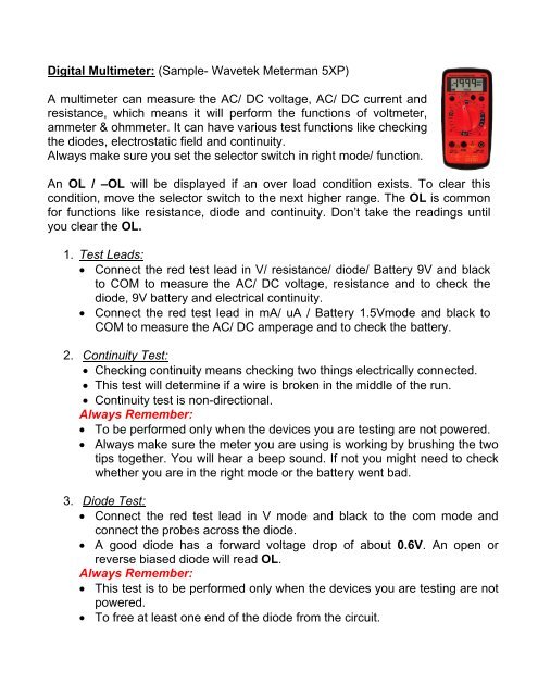
Digital Multimeter: (Sample- Wavetek Meterman 5XP)A <strong>multimeter</strong> <strong>can</strong> <strong>measure</strong> <strong>the</strong> <strong>AC</strong>/ <strong>DC</strong> <strong>voltage</strong>, <strong>AC</strong>/ <strong>DC</strong> <strong>current</strong> <strong>and</strong>resistance, which means it will perform <strong>the</strong> functions of voltmeter,ammeter & ohmmeter. It <strong>can</strong> have various test functions like checking<strong>the</strong> diodes, electrostatic field <strong>and</strong> continuity.Always make sure you set <strong>the</strong> selector switch in right mode/ function.An OL / –OL will be displayed if an over load condition exists. To clear thiscondition, move <strong>the</strong> selector switch to <strong>the</strong> next higher range. The OL is commonfor functions like resistance, diode <strong>and</strong> continuity. Don’t take <strong>the</strong> readings untilyou clear <strong>the</strong> OL.1. Test Leads:• Connect <strong>the</strong> red test lead in V/ resistance/ diode/ Battery 9V <strong>and</strong> blackto COM to <strong>measure</strong> <strong>the</strong> <strong>AC</strong>/ <strong>DC</strong> <strong>voltage</strong>, resistance <strong>and</strong> to check <strong>the</strong>diode, 9V battery <strong>and</strong> electrical continuity.• Connect <strong>the</strong> red test lead in mA/ uA / Battery 1.5Vmode <strong>and</strong> black toCOM to <strong>measure</strong> <strong>the</strong> <strong>AC</strong>/ <strong>DC</strong> amperage <strong>and</strong> to check <strong>the</strong> battery.2. Continuity Test:• Checking continuity means checking two things electrically connected.• This test will determine if a wire is broken in <strong>the</strong> middle of <strong>the</strong> run.• Continuity test is non-directional.Always Remember:• To be performed only when <strong>the</strong> devices you are testing are not powered.• Always make sure <strong>the</strong> meter you are using is working by brushing <strong>the</strong> twotips toge<strong>the</strong>r. You will hear a beep sound. If not you might need to checkwhe<strong>the</strong>r you are in <strong>the</strong> right mode or <strong>the</strong> battery went bad.3. Diode Test:• Connect <strong>the</strong> red test lead in V mode <strong>and</strong> black to <strong>the</strong> com mode <strong>and</strong>connect <strong>the</strong> probes across <strong>the</strong> diode.• A good diode has a forward <strong>voltage</strong> drop of about 0.6V. An open orreverse biased diode will read OL.Always Remember:• This test is to be performed only when <strong>the</strong> devices you are testing are notpowered.• To free at least one end of <strong>the</strong> diode from <strong>the</strong> circuit.
4. Measuring Voltage: (Volts)• Select <strong>the</strong> desired range.• Always connect <strong>the</strong> test probes across <strong>the</strong> device to <strong>measure</strong> <strong>the</strong><strong>voltage</strong>.Always Remember:• To <strong>measure</strong> <strong>the</strong> right <strong>voltage</strong> (<strong>AC</strong>/ <strong>DC</strong>)• Do not exceed <strong>the</strong> rated <strong>voltage</strong> of <strong>the</strong> meter.5. Measuring Current: (Amps)• Select <strong>the</strong> desired range.• Turn OFF <strong>the</strong> power <strong>and</strong> open <strong>the</strong> circuit to make <strong>the</strong> <strong>measure</strong>mentpoints.• Connect <strong>the</strong> test probes in series with <strong>the</strong> load <strong>and</strong> turn ON <strong>the</strong> power.• Use <strong>current</strong> clamps to <strong>measure</strong> <strong>current</strong> >10A (not for <strong>the</strong> shown model)Always Remember:• Turn OFF <strong>the</strong> power before connecting <strong>the</strong> test probes• Make sure <strong>the</strong> open circuit <strong>voltage</strong> is < 1000V.• Always <strong>measure</strong> <strong>current</strong> in series with <strong>the</strong> load <strong>and</strong> never <strong>measure</strong> a<strong>current</strong> across <strong>the</strong> <strong>voltage</strong> source.• To avoid injury, do not attempt to <strong>measure</strong> <strong>the</strong> <strong>current</strong> of an open circuitif <strong>the</strong> <strong>voltage</strong> is greater than <strong>the</strong> rated <strong>voltage</strong> of <strong>the</strong> meter.6. Measuring Resistance: (Ohms)• Select <strong>the</strong> desired range.Always Remember:• To wait until you discharge <strong>the</strong> capacitance that affects <strong>the</strong> reading.• To connect <strong>the</strong> test probes across <strong>the</strong> resistance.• Never <strong>measure</strong> a resistance across a Voltage source or powered circuit.7. Testing <strong>the</strong> Battery:• Connect <strong>the</strong> red test lead depending on <strong>the</strong> battery <strong>voltage</strong> (9V or 1.5V)• Connecting <strong>the</strong> proper test probe across <strong>the</strong> battery will apply anappropriate load to <strong>the</strong> battery.• For 1.5V Battery if <strong>the</strong> reading is >1.2V GOODFor 9.0V Battery if <strong>the</strong> reading is >7.2V GOOD
8. Additional Features:• HOLD button will capture <strong>and</strong> display <strong>the</strong> <strong>measure</strong>d readingcontinuously.Pressing <strong>the</strong> HOLD button again will release <strong>the</strong> locked reading.• MIN MAX button is used to <strong>measure</strong> <strong>the</strong> minimum <strong>and</strong> maximum valuesof <strong>the</strong> reading. To be in this mode you need to press <strong>the</strong> MIN MAXbutton for < 1sec. To change <strong>the</strong> modes from max to min <strong>and</strong> min tomax you need to press <strong>the</strong> MIN MAX button. To disable this mode, youneed to press <strong>the</strong> MIN MAX button for >1sec.• NON CONT<strong>AC</strong>T VOLTAGE (NCV) Senses <strong>the</strong> steady state electrostaticfield produced by <strong>AC</strong> <strong>voltage</strong> (70-600V<strong>AC</strong>) through insulation withoutrequiring contact to <strong>the</strong> bare conductor. A red glow at <strong>the</strong> tip <strong>and</strong> abeeping noise (if not switched OFF) indicates <strong>the</strong> presence of <strong>voltage</strong>.Troubleshooting:If <strong>the</strong> meter is not operating normally, here are <strong>the</strong> main 3 things to test:• Check <strong>the</strong> continuity of test probes.• Ensure <strong>the</strong> battery is in good operational condition (Replace <strong>the</strong> batteryas soon as you see <strong>the</strong> low battery icon to get accurate readings)• Check <strong>the</strong> fuse (0.315A) if you are having problems with <strong>current</strong> ranges.Category Levels:The Category levels determine <strong>the</strong> safety of <strong>the</strong> meter to withst<strong>and</strong> <strong>voltage</strong>spikes when used in different circuits.• CAT I – Protected Electronic Circuits• CAT II – Receptacle outlet circuits, Plug in loads• CAT III – Distribution Wiring (Main Bus, Feeders, Branch Circuits,Permanent installed Loads)• CAT IV – Utility Level <strong>and</strong> Outside Cable Runs.
St<strong>and</strong>ard Organizations:• UL (Underwriters Laboratories)• NEMA (National Electrical Manufacturers Association)NEMA Enclosure Types: The classification is based on <strong>the</strong> degree ofProtection in different environmental conditions.• Check <strong>the</strong> h<strong>and</strong>out for different types of NEMA Ratings• NFPA (National Fire Protection Association)• IEC ( International Electrotechnical Commission)IEC writes international st<strong>and</strong>ards for electrical <strong>and</strong> electronictechnologies <strong>and</strong> practices.Industrial Controls:• Electrical Symbols: All electrical contact symbols are shown in <strong>the</strong>irDe-Energized state <strong>and</strong> are used to indicate <strong>the</strong> path of <strong>current</strong> flow.Check <strong>the</strong> h<strong>and</strong>out for wiring symbols. The Schematic diagrams arearranged for simplicity <strong>and</strong> ease of underst<strong>and</strong>ing circuits without regardfor <strong>the</strong> actual physical location of any components.• General Motor Control (Most Basic Control):This is <strong>the</strong> most generallayout of a motor &control circuit.Always connect <strong>the</strong>control loads parallel.
• I/O Devices: These are <strong>the</strong> devices used to control <strong>the</strong> logic/ <strong>current</strong>flow in <strong>the</strong> circuit.Push Buttons & Selector Switches:Two Types(a) Momentary <strong>and</strong> (b) MaintainedN.O (Normally Open): When <strong>the</strong> contacts arein Normally Open state (De-energized), <strong>the</strong>contacts are normally opened. As soon as youpush <strong>the</strong> switch, <strong>the</strong> contacts close <strong>and</strong> it willallow <strong>the</strong> <strong>current</strong> to pass through <strong>the</strong> circuit.N.C (Normally Close): The contacts remainin <strong>the</strong> closed state (de-energized) allow <strong>the</strong><strong>current</strong> to pass through until <strong>the</strong> switch isenergized. This is mainly used for e-stopcircuits.Pilot Lights:These are used toindicate <strong>the</strong> statusof operation of <strong>the</strong>circuit <strong>the</strong>y areused in to <strong>the</strong>operator.Different colors indicate different states:Red- Danger/ Emergency/ FaultyGreen- Safe/ RunningAmber- Warning/Caution/ AbnormalBlue- M<strong>and</strong>atory ActionClear, White, Gray <strong>and</strong> Black- No specific meaning assigned
Transformers: The power source to <strong>the</strong> motor is frequently higher than <strong>the</strong>control circuit. So we use <strong>the</strong> single phase transformers to step down to <strong>the</strong>required control <strong>voltage</strong>. Provide proper fusing on both <strong>the</strong> line side (Primary)<strong>and</strong> <strong>the</strong> load side (Secondary) of <strong>the</strong> transformer.Control Relays: Unlike contactors, this device is used to switch multiplecontrol circuits / loads. The contacts in <strong>the</strong> control relay are small because<strong>the</strong>y are used to h<strong>and</strong>le <strong>the</strong> control circuits.Poles describe <strong>the</strong> number of isolated circuits that <strong>can</strong> pass thru <strong>the</strong> relay atone time.Throw describes <strong>the</strong> number of different closed-contact positions per pole.This is <strong>the</strong> number of different circuits that each pole controls.Break describes <strong>the</strong> number of separate contact points used to open or closeeach circuit.Time Delay Relays:Time delays have 2 functions.(i) On-delay indicates that a timer will turn on <strong>and</strong> its contacts will changestate at a predetermined time after <strong>the</strong> timer receives a signal to turn on.(ii) Off delay indicates that a timer will turn off at a predetermined time after<strong>the</strong> timer receives a signal to turn off.
Circuit Breaker & SCCR Ratings:Circuit breakers provide a manual means of energizing <strong>and</strong> deenergizinga circuit. This <strong>can</strong> be re-activated quickly after a short circuit /overload is cleared.The <strong>voltage</strong> rating of a circuit breaker shows <strong>the</strong> ability to suppress <strong>the</strong>internal arc that occurs when <strong>the</strong> circuit breaker's contacts open.The continuous <strong>current</strong> rating of a circuit breaker is <strong>the</strong> maximumcontinuous <strong>current</strong> a circuit breaker is designed to carry without tripping.The Interrupt <strong>current</strong> rating of a circuit breaker is <strong>the</strong> maximum <strong>current</strong> acircuit breaker is designed to h<strong>and</strong>le at rated <strong>voltage</strong>.The Short Circuit Current Rating (SCCR) on components is <strong>the</strong>maximum amount of short circuit <strong>current</strong> <strong>the</strong> component <strong>can</strong> h<strong>and</strong>le.Advantages:Senses <strong>and</strong> <strong>measure</strong>s over <strong>current</strong> <strong>and</strong> trip when a fault occurs.Shunt Trip is an accessory on circuit breaker used to remotely trip <strong>the</strong>Circuit Breaker.Contactors: There are 2 circuits involved in <strong>the</strong> operation of a contactor.(a) The control circuit is connected to <strong>the</strong> coil of an electromagnet <strong>and</strong>(b) The power circuit is connected to <strong>the</strong> stationary contacts.
Coils: These are used in electromagnetic circuits to open or close itsrespective contacts when energized.When <strong>the</strong> control circuit supplies <strong>the</strong> power to <strong>the</strong> coil, it generates <strong>the</strong>magnetic field, which in turn closes <strong>the</strong> contacts to make <strong>the</strong> <strong>current</strong> flowfrom line to load side. This will de-energize when <strong>the</strong>re is no power to<strong>the</strong> coil.When <strong>the</strong> motor contactor is combined with an overload, <strong>the</strong>n it is calleda Motor Starter. There are 2 basic types: 1. NEMA <strong>and</strong> 2. IECWhen <strong>the</strong> motor starter is incorporated with a short- circuit protection<strong>and</strong> a disconnecting device, <strong>the</strong>n it is called a Combination Starter.2. Overloads: (N.C) <strong>the</strong>se are used to protect <strong>the</strong> motors from overheating.Reasons- Low Line Voltage; Open phase in a 3-Phase system; overloading <strong>the</strong> motor => Higher Current draw => Overheating.When <strong>the</strong> motor generates high temperatures, <strong>the</strong> <strong>the</strong>rmal relay opens(trips) to protect <strong>the</strong> motor from damage.We <strong>can</strong> reset <strong>the</strong> overload relay after <strong>the</strong> overload condition is cleared.
Test Button on <strong>the</strong> overload is used to test <strong>the</strong> electronic functions.Overload Relay Class determines <strong>the</strong> time it takes to trip <strong>the</strong> overload.(E.g. Class-10 OL relay allows up to 600% of FLA for up to 10 seconds)Manual Motor Starter Protector: This consists of a manual contactor <strong>and</strong> anoverload protection device.Soft Starters:• What is a Soft Starter <strong>and</strong> why do we use it?A soft starter is an electronic device that controls <strong>the</strong><strong>voltage</strong> of <strong>the</strong> motor by giving smooth transition fromstart to stop. The soft starter is designed so that it<strong>can</strong> adjust <strong>the</strong> initial <strong>voltage</strong> to <strong>the</strong> motor by userdefined acceleration (soft start) <strong>and</strong> decelerationperiod (soft stop).Advantages:• We <strong>can</strong> limit/ reduce <strong>the</strong> starting <strong>current</strong>s &torques.• We <strong>can</strong> have a better control of acceleration &deceleration.• Less mechanical stress by avoiding <strong>the</strong> wear &tear of belts, chains, gears <strong>and</strong> bearings.Cable Wiring- Current & Temperature Carrying Capacity:Before selecting <strong>the</strong> wire/cable, youalways need to check that it is rated toproper <strong>voltage</strong>, temperature <strong>and</strong>ampacity. Check <strong>the</strong> wire gauge quickreference for proper wire selection.
<strong>AC</strong> Motors:The basic concept of an <strong>AC</strong> motor is to take <strong>the</strong> electrical energy; generateelectromagnetic fields <strong>and</strong> convert it to mechanical energy.The motor has mainly <strong>the</strong> parts shown in <strong>the</strong> picture below.Stator is <strong>the</strong> stationary part of<strong>the</strong> electromagnetic circuit.This is made of many thinmetal laminations, whichreduce <strong>the</strong> energy lossescompared to solid core.Coils of insulated wire areinserted in <strong>the</strong> slots of <strong>the</strong>stator <strong>and</strong> ends of <strong>the</strong> coilsare connected directly to <strong>the</strong>power source to generate <strong>the</strong>required electromagnetic field.Rotor is <strong>the</strong> rotary part of <strong>the</strong>electro-magnetic circuit. This is made of thin laminations of steel. The conductorbars are inserted in <strong>the</strong> slots instead of conductor wires <strong>and</strong> are electrically &mechanically connected to <strong>the</strong> end rings. The steel shaft is <strong>the</strong>n inserted to form<strong>the</strong> rotor assembly.The Enclosure consists of <strong>the</strong> frame <strong>and</strong> end brackets. The stator is mountedinside <strong>the</strong> frame <strong>and</strong> <strong>the</strong>n <strong>the</strong> rotor is inserted inside <strong>the</strong> stator with a slight airgap. The enclosure protects <strong>the</strong> parts inside from environmental elements.Bearings are mounted on <strong>the</strong> shaft to support rotor rotation. The Fan is alsomounted on <strong>the</strong> rotor, which is used to cool <strong>the</strong> motor.Reasons for Motor Failure:• Bearing Failure, Vibration, Harsh Environment, Improper motorselection, Inadequate Installation, Inadequate Maintenance, ElectricalProblems, Unbalanced Voltage, Mechanical Failure <strong>and</strong> MotorRepair.
Three Phase System:• This is <strong>the</strong> most commonform of transportation of<strong>current</strong>.• The phase shift between<strong>the</strong> <strong>voltage</strong>s is 120degrees.• Look at <strong>the</strong> picture belowhow to <strong>measure</strong> <strong>the</strong> lineline<strong>voltage</strong> <strong>and</strong> <strong>voltage</strong>swith respect to ground forWye (480V<strong>AC</strong>) & Delta (240V<strong>AC</strong>) type of connections.• The picture shown above is <strong>the</strong> motor connections inside <strong>the</strong> motor j.box forhigh & low <strong>voltage</strong>s
Motor Name Plate Details:The nameplate information on <strong>the</strong> motor gives us <strong>the</strong> detailed informationlike <strong>the</strong> Model #, Enclosure type, Insulation Class, Duty type, HP, Voltage,full load amps (FLA), Frequency (Hz), phase(PH), Service Factor (SF),RPM, power factor (PF), wiring details, efficiency <strong>and</strong> temperaturenecessary for proper application.Service Factor: This is <strong>the</strong> number that <strong>can</strong> be multiplied by <strong>the</strong> rated HPof <strong>the</strong> motor to determine <strong>the</strong> maximum operating HP.Always remember that any motor operating continuously will have areduced service life.Insulation Class: This describes <strong>the</strong> motor insulation to h<strong>and</strong>le heat. Theclass determines <strong>the</strong> maximum allowable temperature raise from ambienttemperature (40°C). For every 10°C rise in temperature, <strong>the</strong> motorinsulation expectancy life is cut by half.Voltage Variation: A small variation in<strong>voltage</strong> <strong>can</strong> have a dramatic impact on <strong>the</strong>motor performance.If <strong>the</strong>re is a <strong>voltage</strong> drop of 10%, <strong>the</strong> motorperformance is reduced by 20%. This maycause <strong>the</strong> motor not to start or keep up to<strong>the</strong> rated speed.If <strong>the</strong>re is a <strong>voltage</strong> hike of 10%, <strong>the</strong> motorstarting torque will increase by 20% <strong>and</strong> willresult in <strong>the</strong> damage to <strong>the</strong> motor duringstart-up by increasing <strong>current</strong>s <strong>and</strong> temperature.• Things to be keep in mind while wiring:An electrical connection that is over tightened <strong>can</strong> cause several problems.Over tightening <strong>can</strong> flatten <strong>the</strong> conductor to a point that it breaks. Overtightening <strong>the</strong> connection <strong>can</strong> also cause <strong>the</strong> connection to heat up. Theconductor will push away from <strong>the</strong> stud area causing <strong>the</strong> conductor to cupwhich reduces <strong>the</strong> amount of contact with <strong>the</strong> lug. This smaller contact areacauses overheating just as a loose connection will. Over tightening <strong>can</strong>damage <strong>the</strong> lug by causing small hairline cracks in <strong>the</strong> lug.
Connections <strong>can</strong> be over-torque as well as under-torque. The inch-poundsof torque required by <strong>the</strong> manufacturer is <strong>the</strong> ideal value that must beachieved as closely as possible to get <strong>the</strong> most effective electricalconnection, minimizing creep <strong>and</strong> cold flow of <strong>the</strong> conductor metal <strong>and</strong>prevent overheating due to increased contact resistance.Electrical Safety:There are mainly 3 steps that need to be taken to be safe while workingwith electricity.• Recognize Hazards:To recognize this, you need to know which situations <strong>can</strong> place you indanger. Listed below are some possibilities of danger:1. Inadequate sizing of wire like wire gauge, ampacity & overload.2. Exposed Electric parts- Incorrect wiring practice.3. Overhead power rails.4. Wires with bad insulation <strong>can</strong> give shocks.5. Improper grounding- Electrical systems & tools that are not properlyinsulated are dangerous.6. Overloading <strong>the</strong> circuits- Draws too much <strong>current</strong> <strong>and</strong> <strong>can</strong> lead to fire.7. Use ladders that are non conductive to electricity.8. Working in wet environmental conditions is dangerous.9. Using wrong PPE (Proper protective equipment), tools <strong>and</strong> somechemicals.10. Make sure you are working on De-energized circuits.11. Circuits with over/under sizing are a good chance for danger.• Evaluate Hazards:Always think that you are working in a hazardous environment <strong>and</strong> youmust constantly evaluate your risk. You <strong>can</strong> see clues that <strong>the</strong>re is anexistence of electrical Hazard.1. Tripped circuit breakers <strong>and</strong> blown fuses show that too much <strong>current</strong>is flowing in a circuit. This condition might be due to several factorssuch as malfunctioning of equipment or a short. You need todetermine <strong>the</strong> cause in order to control <strong>the</strong> hazard.
2. Any wire or connection that feels warm indicates that <strong>the</strong>re is toomuch <strong>current</strong> flowing in that circuit. You need to evaluate <strong>and</strong> prevent<strong>the</strong> risk.3. A burning odor may indicate overheated insulation.4. A GFCI that trips often indicates that <strong>the</strong>re is a <strong>current</strong> leakage from<strong>the</strong> circuit.5. Check for <strong>the</strong> worn out or damaged insulation around a wire toprevent <strong>the</strong> hazards ahead.You need to evaluate <strong>the</strong> seriousness of any damage <strong>and</strong> decide whatactions need to be performed to eliminate <strong>the</strong>se hazards.• Control Hazards:The best way to control hazards is to follow <strong>the</strong> NEC <strong>and</strong> OSHAregulations. Here are some of <strong>the</strong> tips:1. Always treat <strong>the</strong> conductors (Energized / De-energized) as energizedunless <strong>the</strong>y are locked out <strong>and</strong> tagged.2. Lock out <strong>and</strong> tag out <strong>the</strong> circuits <strong>and</strong> machines when you want toservice.3. Prevent overloading of <strong>the</strong> wire by selecting <strong>the</strong> right size.4. Prevent exposure to live wire <strong>and</strong> parts by providing insulation.5. Prevent shocking <strong>current</strong>s by proper grounding <strong>and</strong> by using GFCI.Always lock out <strong>and</strong> tag out circuits for service.


