Installation Instructions - Kaldewei
Installation Instructions - Kaldewei
Installation Instructions - Kaldewei
You also want an ePaper? Increase the reach of your titles
YUMPU automatically turns print PDFs into web optimized ePapers that Google loves.
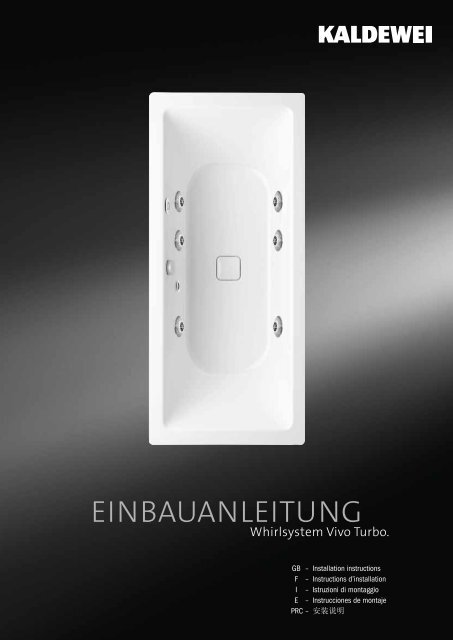
EINBAUanleitungWhirlsystem Vivo Turbo.GB – <strong>Installation</strong> instructionsF – <strong>Instructions</strong> d’installationI – Istruzioni di montaggioE – Instrucciones de montajePRC – 安 装 说 明
VIVO TURBOINSTALLATION INSTRUCTIONSFOR SANITARY FITTERTake a little time and read the installation instructions ofthis whirl system carefully. In these installation instructions,the pictograms described below are used. They refer to instructionsand notes which require your special attention.The function of the whirl system may be disturbed.Your health or that of the person(s) using the whirlsystem may be damaged.EXPLANATION• <strong>Kaldewei</strong> prepared these operating instructions to thebest of its knowledge.• <strong>Kaldewei</strong> reserves the right to change the contents ofthe operating instructions without being obliged to informany third parties.• <strong>Kaldewei</strong> reserves the right to modify and improve thetechnical plant without being obliged to inform any thirdparties. Please read the attached additional information,if necessary.• No part of these operating instructions may be reproducedor transferred otherwise without the express approvalof <strong>Kaldewei</strong>.CONTENTSSCOPE OF SUPPLY...................................................... 2OPTIONAL EQUIPMENT................................................ 2TRANSPORT............................................................... 2BINDING INSTALLATION INSTRUCTIONS......................... 3SETTING UP THE WHIRLPOOL....................................... 3CONNECTION OF THE DRAIN AND OVERFLOWFITTINGS.................................................................... 4FILLING THE WHIRLPOOL............................................. 4ALIGNMENT OF THE WHIRLPOOL.................................. 4BATHTUB FIXING DEVICES AND SOUND INSULATION...... 5CONNECTION TO ELECTRICAL MAINS............................ 5FUNCTIONAL CHECK................................................... 6BRICKWORK LINING OR CASING OF THE WHIRLPOOL..... 7TROUBLE SHOOTING................................................... 8DGBFIEPRC<strong>Installation</strong> <strong>Instructions</strong>Sanitary fitter1
SCOPE OF SUPPLYTRANSPORT<strong>Kaldewei</strong> whirl systems are completely preassembled inthe workshop and are subjected to extensive quality andfunctional checks.When factory-installed components are modified,the pledge of warranty will become invalid.Check the supply for completeness and possibletransport damage immediately upon delivery of thewhirlpool.VIVO TURBO/PLUS WHIRL SYSTEMThe following instructions have to be observed when transportingthe <strong>Kaldewei</strong> whirl systems:1. Handle the whirlpool with utmost care.2. Transport the whirlpool in its transport box only andavoid bumping.3. When carrying the whirlpool, hold on to the sides only -never to the instrument enclosures or hose systems.DGBFIVIVO TURBO• Whirlpool with drain and overflow fittings and siphontrap (A)• 6 massage nozzles (B), arrangement depending on thetub model• Sealed key pad (C)• Level sensor (D)• Height-adjustable pedestal (E)BCAModel example<strong>Kaldewei</strong> shall not assume any liability for damageincurred due to improper intermediate storage andfor damage in transport resulting from the noncompliancewith the above instructions.The cable binders which serve to secure the controlsystem during transport have to be removed.EPRC<strong>Installation</strong> <strong>Instructions</strong>Sanitary fitterDEOPTIONAL EQUIPMENT• Drain and overflow fittings with integrated inlet• Underwater spotlight or spectral light• Massage nozzles illuminated in white or blue• Handles depending on bathtub model2
BINDING INSTALLATION INSTRUCTIONSSETTING UP THE WHIRLPOOLThe mounting of the whirlpool, the connection tothe electrical mains and the elimination of malfunctionsand defects must only be carried out bya specialist shop which is able to prove its skillsand competence with regard to the application ofnational safety regulations, e.g. to power and watersupply/discharge, to the relevant authorities.During installation, protect the whirlpool surfacesand the whirl system from damage.Avoid soiling of any kind which might cause obstructionswhen installing the waste pipe.Instrument cases or electrical components remainunaffected when installing the whirl system.The floor space required for the whirlpool and the attachedequipment results from the outer dimensions of the whirlsystem. Within that area, the entire equipment has beeninstalled in the workshop ready for connection.DGBFIEVIVO TURBOWhen factory-installed components are modified,the pledge of warranty will become invalid.Upon completion of the work (performed by thesanitary and electrical fitters), the whirl system hasto be subjected to a functional check (see page 6).All work has to be performed using special technicaltools.The load capacity of the floor on which the whirlpooltub is installed should correspond to the indicatedfloor load of the whirlpool tub (see „TechnicalInformation - Whirl Systems“).The distance between siphon trap and floor has tobe at least 10 mm.An underfloor heating must not be operated underneaththe whirlpool.For other bathtub model-specific notes please observe theBathtub Models supplementary sheet.<strong>Installation</strong> <strong>Instructions</strong>Bathtub ModelsPRC<strong>Installation</strong> <strong>Instructions</strong>Sanitary fitter3
VIVO TURBOCONNECTION OF THE DRAIN ANDOVERFLOW FITTINGS• Connect the drain and overflow fittings to the local sewerage.Pay attention to the proper fit of the screwed andplug-in connections.FILLING THE WHIRLPOOL• Close the drain and overflow fittings and fill the whirlpoolwith water.The water remains in the whirlpool while the bathtubcasing is mounted.ALIGNMENT OF THE WHIRLPOOLThe height-adjustable feet enable easy and safe alignmentof the whirlpool.The height-adjustable feet only serve as aids to setup the whirlpool in exactly horizontal position. Additionalbathtub fixing devices must be mounted.The black sound-isolating elements (A) must be setwith their hard, light-coloured coated side on theoutside into the blue foot caps (B).• To align the whirlpool, turn the height-adjustable feet (C)in or out.Align the bathtub in exactly horizontal position bymeans of a spirit level to ensure a reliable waterdrainage (drainage test).When aligning the whirlpool, make sure that thefour feet with the sound absorbers (A) are allstanding firmly on the ground.• After the alignment, secure the height-adjustable feetagainst displacing by means of the hexagon nut (D).DCBDGBFIEPRC<strong>Installation</strong> <strong>Instructions</strong>Sanitary fitterA4
VIVO TURBOBATHTUB FIXING DEVICES ANDSOUND INSULATIONFasten the whirlpool in the shown positions by means ofbathtub anchors (not included in the scope of supply).When installing the bathtub fixing devices or soundinsulation sets available in sanitary shops, themanufacturer‘s instructions have to be observed.Parts mounted to the whirl system must not beremoved.AREAS FOR THE ATTACHMENT OF BATHTUB FIXINGDEVICESThe <strong>Kaldewei</strong> whirl systems comply with DIN 4109/A1„Sound insulation in building construction“ if the otherconstruction requirements are met and the <strong>Kaldewei</strong> bathtubsound-absorbing set BWS is used.<strong>Kaldewei</strong> bathtub sound-absorbing set BWS(article number: 6876.7559.0000)CONNECTION TO ELECTRICAL MAINSAfter the whirlpool has been fastened, the work of the sanitaryfitter is completed for the time being and the electricalfitter’s work must be performed (from Page 9 of theseinstallation instructions).The mounting of the whirlpool, the connection tothe electrical mains and the elimination of malfunctionsand defects must only be carried out bya specialist shop which is able to prove its skillsand competence with regard to the application ofnational safety regulations, e.g. to power and watersupply/discharge, to the relevant authorities.The electrical fitter must be provided with the installationinstructions (or copies of pages 9 to 16)until his work is completed.FURTHER ON PAGE 9<strong>Installation</strong> <strong>Instructions</strong>Electrical fitterDGBFIEPRC<strong>Installation</strong> <strong>Instructions</strong>Sanitary fitter5
FUNCTIONAL CHECKVIVO TURBOAfter the whirlpool has been set up, the drain and overflowfittings connected and the work of the electrical fittercompleted, the whirl system has to be subjected to a functionalcheck.1. VISUAL INSPECTION• Check the whirl system for visible damage.• Check the whirlpool for horizontal installation (drainagetest).• Check the proper attachment of fixing devices andsound insulation.• The cable binders which serve to secure the control systemduring transport have to be removed.• Check the whirlpool for cleanness.Instrument cases or electrical components remainunaffected when installing the whirl system2. FUNCTIONAL TEST WITH THE WHIRLPOOL EMPTY• It is not possible to switch on the whirl system and theoptional lighting (see operating instructions, page 7).3. FILLING THE WHIRLPOOL• Close the drain and overflow fittings.• Fill the whirlpool with water (initial temperature between35°C and 45°C) up to a water level of at least 2 cmabove the level sensor.• Wait for 10 minutes, then subject the whirl system to aleakage test.6. DRAINING THE WHIRL POOL• Switch on all the functions of the whirl operation.• Switch on the optional lighting.• Switch the air admixture on• Open the drain and overflow fittings and let the waterdrain off.• Check the waste pipes (siphon) for leakages.• The whirl system, the optional lighting and the air admixturemust switch off automatically if the water level fallsbelow the minimum level (see operating instructions,page 6).If the whirl system has to be readjusted or defectivecomponents exchanged, the complete functionalcheck has to be repeated.DGBFIEPRC<strong>Installation</strong> <strong>Instructions</strong>Sanitary fitter• Wait for 10 minutes, then carry out a leakage test.4. CHECK THE DIRECTION OF ROTATION• Switch on the whirl system and let it run at minimumintensity (see operating instructions, page 7).• The propellers of the massage nozzles must rotate anticlockwise.5. FUNCTIONAL CHECK• Switch on the whirl system and let it run for approx.10 minutes.• Let the whirl system run alternately at minimum andmaximum intensity (see operating instructions, page 7).• Switch on the interval function and let it run (for an automaticincrease and/or reduction of the intensity duringthe on-time - see operating instructions, page 7).• Switch the optional lighting on and off (see operatinginstructions, page 7).• Switch the air admixture on and off.6
VIVO TURBOBRICKWORK LINING OR CASINGOF THE WHIRLPOOLAfter the functional check, the whirlpool can be brick-linedand tiled.The brickwork lining or other casing has to beinstalled keeping a minimum distance of 15 mmfrom the system components.For installation of all tub models, only a slightrecess for the system components is to be considered.A brick lining flush with the tub is thus notpossible. For further information, please contactyour <strong>Kaldewei</strong> sales consultant.If whirlpools are fitted with <strong>Kaldewei</strong> panels (e.g.PUNTA DUO 3, VAIO DUO 3, STUDIO/STAR), suchpanels must not be sealed with silicone or pointedto ensure the circulation of air.For any servicing work possibly to be performed, two inspectionopenings with a minimum size of 400 mm x 400 mmand 200 mm x 200 mm (height x width) have to be providedat the shown locations. It is absolutely necessary toprovide the inspection opening near the control systemwith an air grid (at least 80 cm² ventilation cross-section)to allow the air to circulate underneath the pool.RECOMMENDATION<strong>Kaldewei</strong> inspection frame with integrated air grid(article number: 6872.7283.0000)<strong>Kaldewei</strong> inspection frame without air grid(article number: 6872.7284.0000)DGBFIEPRC<strong>Installation</strong> <strong>Instructions</strong>Sanitary fitterFor data on size and position of the inspection openingsyou are referred to the Bathtub Models supplementarysheet.<strong>Installation</strong> <strong>Instructions</strong>Bathtub Models7
TROUBLE SHOOTINGVIVO TURBOIn the case of malfunctions and defects of the whirl system,please, inform an authorized dealer or the <strong>Kaldewei</strong>after-sales service.In this case, you should have the name and serial numberof your whirl system (see cover of manual) ready.The installation of the whirlpool, the electricalconnection and the remedy of malfunctions anddefects must be carried out by a specialized dealerwho is able to prove to the authorities concernedhis knowledge and competence as to the applicationof the national safety regulations, e.g. withregard to the power and water supply/discharge.The inspection chamber of the whirl system may beopened by authorized dealers or by the <strong>Kaldewei</strong>after-sales service only.If you wish to ask any questions about your whirl system,please, do not hesitate to contact the <strong>Kaldewei</strong> after-salesservice.KALDEWEI AFTER-SALES SERVICEPhone +49 (0) 23 82 - 785-0Facsimile +49 (0) 23 82 - 785-200E-Mail service@kaldewei.deDGBFIEPRC<strong>Installation</strong> <strong>Instructions</strong>Sanitary fitter8
VIVO TURBOINSTALLATION INSTRUCTIONSFOR ELECTRICAL FITTERTake a little time and read the installation instructions ofthis whirl system carefully. In these installation instructions,the pictograms described below are used. They refer to instructionsand notes which require your special attention.The function of the whirl system may be disturbed.Your health or that of the person(s) using the whirlsystem may be damaged.EXPLANATION• <strong>Kaldewei</strong> prepared these installation instructions to thebest of its knowledge.• <strong>Kaldewei</strong> reserves the right to change the contents ofthe installation instructions without being obliged to informany third parties.• <strong>Kaldewei</strong> reserves the right to modify and improve thetechnical plant without being obliged to inform any thirdparties. Please read the attached additional information,if necessary.• No part of these installation instructions may be reproducedor transferred otherwise without the express approvalof <strong>Kaldewei</strong>.CONTENTSELECTRICAL COMPONENTS....................................... 10OPTIONAL EQUIPMENT.............................................. 10TECHNICAL DATA...................................................... 10BINDING INSTALLATION INSTRUCTIONS....................... 11EQUIPOTENTIAL BONDING......................................... 11MAINS CONNECTION................................................. 12ELECTRICAL OPERATION TEST.................................... 12TROUBLE SHOOTING................................................. 12ANNEXTERMINAL DIAGRAM................................................. 13TERMINAL DIAGRAM (ILLUMINATED MASSAGENOZZLES)................................................................ 14THERMINAL CONNECTION DIAGRAM .......................... 15TERMINAL PLAN CONTROL (UNDERWATER SPOTLIGHT).. 16TERMINAL PLAN CONTROL (SPECTRAL LIGHT).............. 16DGBFIEPRC<strong>Installation</strong> <strong>Instructions</strong>Electrical fitter9
ELECTRICAL COMPONENTSTECHNICAL DATAThe entire electrical equipment of the <strong>Kaldewei</strong>-whirl systemshas been shop-mounted ready for connection.<strong>Kaldewei</strong>-whirl systems are subjected to extensive qualityand functional checks.When factory-installed components are modified,the pledge of warranty will become invalid.VIVO TURBO/PLUS WHIRL SYSTEM• Massage nozzle motors 24 V DC (A)• Control system (B)Nominal voltage of massage nozzle motors 24 V DCNominal output of one massage nozzle motor 70 WTotal nominal output560 WMains connection230 V50/60 cps16 ASafety classIP65OperationSealed key padOPTIONAL EQUIPMENTUnderwater spotlightSpectral light3,5 V3,5 VDGBFIVIVO TURBO• Sealed key pad (C)• Level sensor (D)• Connecting cable 3 x 1.5 mm²AOPTIONAL EQUIPMENTBCDModel exampleEPRC<strong>Installation</strong> <strong>Instructions</strong>Electrical fitter• Underwater spotlight or spectral light with additionalcontrol system• Illuminated massage nozzles with additional control system10
BINDING INSTALLATION INSTRUCTIONSEQUIPOTENTIAL BONDINGVIVO TURBOThe mounting of the whirlpool, the connection tothe electrical mains and the elimination of malfunctionsand defects must only be carried out bya specialist shop which is able to prove its skillsand competence with regard to the application ofnational safety regulations, e.g. to power and watersupply/discharge, to the relevant authorities.<strong>Kaldewei</strong> whirl systems are designed for domesticuse and must be connected in accordance with thelocal regulations of public utility companies.For the connection of the whirl system to the electricalmains, a separate supply line 3 x 2.5 mm²and a 4 mm² line for the equipotential bondinghave to be provided by the customer.The supply line has to be provided with an all-poledisconnecting mains switch with a contact gap ofat least 3 mm to switch off the whirl system (if notbeing used, for servicing work).For service work the whirl system is to be disconnectedfrom the mains - the condenser unloadingtime amounts to 10 minutes.The wiring of the whirl system is suitable for an a.c.voltage of 230 V 50/60 cps.The connection of the whirl system has to be protectedby a 16 A fuse and must be effected via acurrent-operated earth-leakage circuit breaker(30 mA).The whirl system is internally cabled with a protective conductor.• Connect the equipotential bonding (A) of the whirl systemto the local equipotential bonding strip.TYPEEarthing cable - green/yellow, min. 4 mm², copperADGBFIEPRC<strong>Installation</strong> <strong>Instructions</strong>Electrical fitterDuring the electrical installation, protect the whirlpoolsurfaces and the whirl system from damage.Avoid soiling of any kind which might cause obstructionswhen installing the waste pipe.Instrument cases or electrical components remainunaffected when installing the whirl system.When factory-installed components are modified,the pledge of warranty will become invalid.All work has to be performed using special electrictools.11
MAINS CONNECTIONTROUBLE SHOOTINGVIVO TURBO• Connect the whirl system to the local supply network viathe connecting cable 3 x 1.5 mm².The whirl system has to be connected to the mainsunder off-circuit conditions.The supply line has to be provided with an all-poledisconnecting mains switch with a contact gap ofat least 3 mm to switch off the whirl system (if notbeing used, for servicing work).The connection of the whirl system has to be protectedby a 16 A fuse and must be effected via acurrent-operated earth-leakage circuit breaker(30 mA).The standard EN 60 335-2-60 concerning whirlsystems stipulates: „The equipment has to bepermanently connected to a fixed line. Appliancescontaining electrical components have to beplaced or attached such that they cannot fall intothe tub.“Components of the whirl system which carry mainsvoltage (230 V) when active or inactive shall beinaccessible to persons using the bath.ELECTRICAL OPERATION TESTUpon completion of the electrical connection work, thewhirl system has to be subjected to an electrical operationtest.In the case of malfunctions and defects of the whirl system,please, inform an authorized dealer or the <strong>Kaldewei</strong>after-sales service.In this case, you should have the name and serial numberof your whirl system (see cover of manual) ready.The installation of the whirlpool, the electricalconnection and the remedy of malfunctions anddefects must be carried out by a specialized dealerwho is able to prove to the authorities concernedhis knowledge and competence as to the applicationof the national safety regulations, e.g. withregard to the power and water supply/discharge.The inspection chamber of the whirl system may beopened by authorized dealers or by the <strong>Kaldewei</strong>after-sales service only.If you wish to ask any questions about your whirl system,please, do not hesitate to contact the <strong>Kaldewei</strong> after-salesservice.KALDEWEI AFTER-SALES SERVICEPhone +49 (0) 23 82 - 785-0Facsimile +49 (0) 23 82 - 785-200E-Mail service@kaldewei.deDGBFIEPRC<strong>Installation</strong> <strong>Instructions</strong>Electrical fitter1. VISUAL INSPECTION• Check the whirl system for visible damage.• Check the 16 A fuse.• Check the current-operated earth-leakage circuit breaker(30 mA).• Check the all-pole disconnecting mains switch.• Check the cable joints for proper fit.• Check the insulation of the cable joints.Pipework, hose connections and unions remainunaffected by the electrical connection of the whirlsystem.2. FUNCTIONAL TESTAfter the electrical operation test, the whirl system can behanded over to the sanitary fitter.12
TERMINAL DIAGRAMPower input1 x 230 VABCA = Control systemB = Venturi valve 8 W/24 VC = Operating panel, round or ovalD = Level sensor 12 VE = Underwater spotlight/spectral light control system230 V (optional)F = Underwater spotlight/spectral light 3.5 V (optional)G = Nozzle motor shoulder area 24 VH = Nozzle motor waist area 24 VI = Nozzle motor calf area 24 VDGBFIEVIVO TURBOGGFEDIPRC<strong>Installation</strong> <strong>Instructions</strong>Electrical fitterHIH13
TERMINAL DIAGRAM (ILLUMINATED MASSAGE NOZZLES)ABA = Control systemB = Venturi valve 8 W/24 VC = Operating panel, round or ovalD = Level sensor 12 VE = Control system for illuminated massage nozzles (optional)G = Nozzle motor shoulder area 24 VH = Nozzle motor waist area 24 VJ = Nozzle motor calf area 24 VDGBFPower input1 x 230 VCIEVIVO TURBOGGDEIPRC<strong>Installation</strong> <strong>Instructions</strong>Electrical fitterHIH14
TERMINAL CONNECTION DIAGRAMVIVO TURBOABCDEFJGH+-+IN-T1 T2+-+-+-+-+-+-N LPENL4KILA = Solenoid valve+ blue- brownB = Level sensor whirl operation+ whiteIN brown- greenC = Spectral lightT2 whiteT1 brownD = Motor pair calf area+ brown- blueE = Motor pair waist area+ brown- blueF = Motor pair shoulder area+ brown- blueG = Underwater spotlight/spectral lightL brownN blueH = Mains input 3 x 1.5 mm²PE yellow-greenN blueL brown/blackI = Jack for service PCJ = Control transformer fuse 1.25 ATK = Mains input fuse 3.15 ATL = Control system for illuminated massage nozzlesDGBFIEPRC<strong>Installation</strong> <strong>Instructions</strong>Electrical fitterDESIGNATION OF THE WHIRL NOZZLES IN THE VIVO TURBOPLUS SYSTEM (RIGHT-HAND/LEFT-HAND TYPE)A = Sealed key padB = Drain and overflow fittings15
TERMINAL PLAN CONTROL(UNDERWATER SPOTLIGHT)DAGBVIVO TURBOA = Power input 2 x 0.75 mm²Lbrown/blackNblueB = Underwater spotlightT1 whiteT2 brownTERMINAL PLAN CONTROL(SPECTRAL LIGHT)BCBFIEPRC<strong>Installation</strong> <strong>Instructions</strong>Electrical fitterAA = Power input 2 x 0.75 mm²Lbrown/blackNblueB = Spectral light- yellow- green- white+ brownC = Control lineT1 whiteT2 brown16
Franz <strong>Kaldewei</strong> GmbH & Co. KGBeckumer Strasse 33 - 3559229 AhlenGermanyTel. +49 2382 785 0Fax +49 2382 785 200www.kaldewei.com257.899 04/2013


