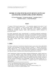
directions, indicating occasional lenses. A typical data from aCPT and a nearby borehole is given in Figure 1.Based on the results of boreholes and CPT tests, the sub<strong>soil</strong>within the site in general, consists of alternation of silty clay, siltand silty sand ranging between soft/loose to medium approximatelydown to the depth of 24.0 m below the ground surface.Below this depth, a gravelly clay layer with average SPT/N blowcount value in the order of 25 is encountered.In the geotechnical model based on the results of in situ tests,laboratory tests and CPTs, it was observed that, down to approximately3.5 m depth, the undrained shear strength values arein the order of s u = 35 kPa. Approximately between the depths of3.5 m and 12.0 m, a silty, clayey sand layer in loose to mediumdensity is encountered. Between the depths 12.0 m and 24.0 m, aclay layer is present having undrained shear strength value in the4 FOUNDATION ENGINEERING EVALUATIONS4.1 Bearing capacityBased on the shear strength model, the ultimate bearing capacity<strong>for</strong> shallow foundations and embankment without consideringthe primary and secondary settlements, is determined by;q net ~ 5 x s uwhereas, q net = 5 x 35 kPa = 175 kPa. There<strong>for</strong>e the allowable<strong>soil</strong> pressure is given as;q all = 70 kPaconsidering a safety factor of FS = 2.5 and without taking into0q c (MPa)0 5 10 15 20f s (kPa)0 100 200 300 400R f (%)0 1 2 3 4 5 6 7Soil DescriptionFillSPT blow count per300mm penetration0 10 20 30 40 50silty Clay5silty Sand10depth (m)15silty Claysandy Silt20silty Clay25GravellyClay30Figure 1. Typical <strong>soil</strong> profile determined by CPT and boringorder of s u = 50 kPa while a 2.0 m thick sand layer is found betweenthe depths of 16.0 m and 18.0 m. Based on the results ofboreholes and CPTs, the consistency increases from stiff to hardbelow 24.0 m depth. The identification properties of the <strong>soil</strong>s encounteredat the site are determined by laboratory tests andsummarised below in Table 1.Table 1. Identification test resultsProperty Sand ClayNatural water content, % * 35-68% passing #200 sieve 10-43 *Liquid limit * 39-83Plastic limit * 12-41Plasticity index * 16-46* not availableaccount the settlements.4.2 SettlementsThe settlement calculations are done both utilising CPT test datawhich enables detailed layering and also utilising the idealisedgeotechnical model. The settlement calculations are carried out<strong>for</strong> a strip foundation width of 4.0 m and a foundation base pressureof 50 kPa and also repeated <strong>for</strong> a 3.0 m high embankmentloading. The results obtained are summarised below in Table 2.It was also recommended in the foundation engineering reportthat the secondary settlements in the order of 10% of these givenvalues should be considered to be realised in the long term.Considering the structural and architectural criteria <strong>for</strong> theplanned structures, calculated settlement values are above the allowablelimits. The allowable settlements were determined asmaximum s = 5.0 cm under the foundations/slabs-on-grade andembankment loading. Ultimately, it was concluded that bothfoundations and slabs-on-grade and/or embankment loadingsshould be supported by <strong>soil</strong> <strong>improvement</strong> and/or deep foundationsystems.
Table 2. Summary of settlement analysesSettlement, cmAnalysisCPTsModelbased onLoading Strip Embankment Strip Embankmenttype foundationfoundationMinimum 12.1 20.2 - -Maximum 23.8 39.3 - -Average 18.7 37.1 16.7 32.9economical advantage because the excavation of the weak <strong>soil</strong>can be avoided. Also, high internal shearing resistance is pr o-vided within the pillar. These pillars act as oversize verticaldrains causing reduction of consolidation time. Schematic principleof the dynamic replacement method is illustrated in Figure2.Weightdropping4.3 Seismicity and risk of <strong>liquefaction</strong>The subject site is located within the first degree earthquakezone in Izmir with a high seismic activity. The <strong>soil</strong> <strong>liquefaction</strong>analyses are per<strong>for</strong>med based on the results of CPT and SPT,and the properties of the encountered sub<strong>soil</strong> in boreholes. Forthis purpose, a seismic risk analysis is utilised per<strong>for</strong>med previously<strong>for</strong> the subject region by Cetinkaya et al. (1993). Accordingly<strong>for</strong> the subject region,FillCompressible<strong>soil</strong>Refilling− Average maximum annual earthquake magnitude: M = 4.8− Most frequent annual magnitude: M = 4.6− Maximum magnitude <strong>for</strong> a return period of 100 years: M =8.4− Magnitude with an annual risk of R = 10%: M = 6.3 (designearthquake)− Bedrock accelerations <strong>for</strong> an epicentral distance to fault lineof 10 km is a = 0.5g, 20 km is a = 0.25g, and 40 km is a =0.12gConsidering that the subject site is located within 20 km distanceto potential fault lines, the maximum bedrock acceleration <strong>for</strong>the design earthquake was considered as 0.25g <strong>for</strong> a service lifeof 100 years. Furthermore, considering the bedrock is at verydeep level and the site is covered with weak alluvial deposits,<strong>soil</strong> amplification is expected during an earthquake and there<strong>for</strong>estructural units within the facility would be subject to accelerationgreater than a = 0.25g. Ultimately, the <strong>liquefaction</strong> analysesare per<strong>for</strong>med <strong>for</strong> ground acceleration values of a = 0.3g and0.4g considering the <strong>soil</strong> amplification effects. The susceptibilityof the sub<strong>soil</strong> <strong>against</strong> <strong>liquefaction</strong> under the earthquake loadingwas also predicted by the method suggested by Robertson (1988)utilising the CPT parameters. Analyses are done <strong>for</strong> the <strong>case</strong>s ofPGA (Peak Ground Acceleration) values a = 0.3g and a = 0.4gboth using the standard penetration blow counts, and CPT resultsseparately. As a result of these analyses, <strong>liquefaction</strong> potentialwas determined in the sand layer existing within the first 12.0 mdepth. Below this level, clayey and silty layers are present ingeneral which are not prone to <strong>soil</strong> <strong>liquefaction</strong>.Consequently, in order to prevent <strong>liquefaction</strong>, <strong>soil</strong> <strong>improvement</strong>was recommended to be implemented at the subject site.5 SOIL IMPROVEMENT WORKSIn the light of ground investigations, dynamic replacementmethod was chosen to be the best solution among the possibleground <strong>improvement</strong> techniques applicable, in terms of economy,time and effectiveness. Soil <strong>improvement</strong> works are realisedutilising dynamic replacement method by French companyof Menard Soltraitement.Dynamic Replacement (DR) is a method in which columns oflarge diameter are <strong>for</strong>med with granular material based on thetechniques developed <strong>for</strong> Dynamic Consolidation in highly compressibleand weak <strong>soil</strong>s. These columns of granular material arecalled “pillars”. This technique is similar to dynamic consolidationbut in this <strong>case</strong>, pounding is used to <strong>for</strong>m large diametergranular pillars through the soft clayey <strong>soil</strong>s to underlying densebearing stratum. This method combines the advantages of dynamicconsolidation with those of stone columns creating anFigure 2. Schematic principle of Dynamic Replacement methodThe equipment used <strong>for</strong> dynamic replacement is similar to thedynamic consolidation equipment i.e. heavy rigs and pounders.However, usually pounder with smaller area is used to facilitatethe penetration capacity (Menard Soltraitement 1999). Heavydynamic replacement (HDR) columns are made with bouldersand cobles using energies exceeding 400 tm per blow. The relationshipbetween the effective depth of attained <strong>improvement</strong>,the pounder weight and the height of the drop is expressed as belowin dynamic consolidation:D = (0.3 to 0.7)W × H(1)where D = maximum depth of <strong>improvement</strong> in meters; W = fallingweight in metric tons; and H = height of drop in meters(Mitchell & Gallagher 1998).Pre-excavation in dynamic replacement allows to constructdeeper columns especially in clays, enabling to obtain very goodresistance parameters even in soft compressible <strong>soil</strong>s when combinedwith HDR method. Construction control methods of dynamicreplacement operation at site are similar to those of dynamicconsolidation.Menard designed the <strong>soil</strong> <strong>improvement</strong> scheme including thequality control testing <strong>for</strong> <strong>Carrefoursa</strong> site in Izmir. For this purpose,the total area was divided into six different zones wheredifferent pillar types are constructed. The total area of the site is64,851 m 2 where the <strong>soil</strong> <strong>improvement</strong> is applied. The propertiesset initially <strong>for</strong> various types of pillars are given below in Table3.Table 3. Details of dynamic replacement schemeTreatment DR HDRPillar Type Type1Type1Type2Type3Type4Type5Grid, m 2 36 36 36 36 32 54Drop Height, 20 20 20 20 20 20mPounder 15 25 25 25 25 25Weight, tBlows per 20 22 22 22 20 3x22Pillar, b/pEnergy,tm/m 2 166.7 305.6 305.6 305.6 312.5 611.1The working plat<strong>for</strong>m level was at +1.50 m where the <strong>soil</strong> <strong>improvement</strong>application is per<strong>for</strong>med. After the <strong>soil</strong> improve mentworks are completed, the level is brought to +3.50 m.