TMS2000 - OEC Fluid Handling, Inc.
TMS2000 - OEC Fluid Handling, Inc.
TMS2000 - OEC Fluid Handling, Inc.

Create successful ePaper yourself
Turn your PDF publications into a flip-book with our unique Google optimized e-Paper software.
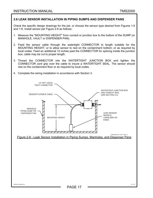
INSTRUCTION MANUAL<strong>TMS2000</strong>2.6 LEAK SENSOR INSTALLATION IN PIPING SUMPS AND DISPENSER PANSCheck the specific design drawings for the job, or choose the sensor type desired from Figures 1-5and 1-6. Install sensor per Figure 2-8 as follows:1. Measure the "MOUNTING HEIGHT" from conduit or junction box to the bottom of the SUMP (orMANHOLE, VAULT or DISPENSER PAN).2. Feed the sensor cable through the watertight CONNECTOR to length suitable for theMOUNTING HEIGHT; or to allow sensor to rest on the containment bottom; or as required bylocal codes. Feed an additional 12 inches past the CONNECTOR for splicing inside the junctionbox; cable may be cut to proper length.3. Thread the CONNECTOR into the WATERTIGHT JUNCTION BOX and tighten theCONNECTOR cord grip over the cable to insure a WATERTIGHT SEAL. The sensor shouldrest on the containment floor or as required by local codes.4. Complete the wiring installation in accordance with Section 3.1/2" NPT LIQUIDTIGHT CONNECTORSENSOR FLEXIBLE CABLEWATERTIGHT JUNCTION BOXAND CONDUIT SEAL(SEE SECTION 3.3)MANHOLEPIPING SUMP ORDISPENSER PANMOUNTING HEIGHTLEAK SENSORMODELS:LS600LDBN ORES825DRAWING NO. 20017 REV. AFigure 2-8 - Leak Sensor Installation in Piping Sumps, Manholes, and Dispenser Pans<strong>TMS2000</strong> Installation.doc 07-11-05PAGE 17