TMS2000 - OEC Fluid Handling, Inc.
TMS2000 - OEC Fluid Handling, Inc.
TMS2000 - OEC Fluid Handling, Inc.

You also want an ePaper? Increase the reach of your titles
YUMPU automatically turns print PDFs into web optimized ePapers that Google loves.
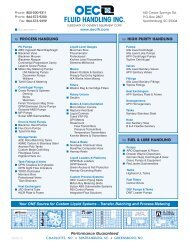
INSTRUCTION MANUAL<strong>TMS2000</strong>2.2 CONTROL CONSOLE INSTALLATIONThe console is the center of operations for any tank monitor system therefore its location should beselected for the operators convenience, or as specified on the DESIGN DRAWINGS.Select a flat wall surface and prepare it with four wall-mounting inserts to accept up to 1/4-inch sizebolts. Allow sufficient room for door to open and for conduit runs to enter ONLY THE CONSOLEBOTTOM. See Figure 1-2 for console dimensions.Note that the console is divided into two electrical areas:NON INTRINSICALLY SAFE (LEFT SIDE) INTRINSICALLY SAFE (RIGHT SIDE)for Power and Controlfor Probe/Sensor signalsFigure 2-1 shows the console interior, again indicating the power and signal separation. THISSEPARATION MUST BE MAINTAINED when conduits are connected. Refer to Section 3 forelectrical conduit and wiring.LOCKDISPLAYCOVEROPTIONALPRINTERI.S. COMPARTMENT COVER(SHOWN OPENED)SECURITYBUTTONRS-232 CONNECTIONFUSE HOLDERCOMMUNICATIONS PORTCONNECTORON/OFF SWITCHPOWERI.S. GROUNDSRS-485 CONNECTION(2) STANDARDNON I.S. RELAY I/Os(2) STANDARDI.S. PROBE INPUTSNON I.S. SLOTCONNECTOR(8) STANDARDI.S. SENSOR INPUTSFigure 2-1 - Control Console InteriorDRAWING NO. 20050 REV. A<strong>TMS2000</strong> Installation.doc 07-11-05PAGE 9