AUTUmN/WiNTER 2010 ISSUE 20 (PDF) - Energy Safe Victoria
AUTUmN/WiNTER 2010 ISSUE 20 (PDF) - Energy Safe Victoria
AUTUmN/WiNTER 2010 ISSUE 20 (PDF) - Energy Safe Victoria

Create successful ePaper yourself
Turn your PDF publications into a flip-book with our unique Google optimized e-Paper software.
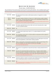
Frequently Asked Questionson the amended Wiring Rules22www.energysafe.vic.gov.auThe new edition of the Australian/NewZealand Standard for Wiring Rules(AS/NZS 3000:<strong>20</strong>07) was released inNovember <strong>20</strong>07 and revised byAmendment 1 in July <strong>20</strong>09.Produced by the joint Standards Australia/Standards New Zealand Committee EL-001,the revised edition expands on issues relatingto electrical installations, improves safeguardsand addresses the needs and expectationsof stakeholders.The amended edition of the Wiring RulesStandard is available in Australia from StandardsAustralia’s distributor of Australian Standards,SAI Global at www.saiglobal.com/shop or131 242 and in New Zealand from StandardsNew Zealand at www.standards.co.nzenergysafe published some of the FrequentlyAsked Questions (FAQs) and answers whichhave been developed by the committeeresponsible for the Wiring Rules (<strong>20</strong>07)and Amendment 1 in Issues 17, 18 and 19.Further FAQs are published here. Theyexplain some of the issues which have beenraised by users of the Standard. This isthe last instalment of FAQs.FAQ 022/<strong>20</strong>09: AS/NZS 3000:<strong>20</strong>07—CLAUSE 3.12.3.23.12.3.2 Clearances – <strong>Safe</strong>ty warningsQuestion 022/<strong>20</strong>09: What are suitable devicesor notices for safety warnings near aerialconductors?Answer: The warning notice should be locatedon each electricity pole. The signs should havethe same dimensions and colours as thoselisted in AS 1319. Some examples of signs aregiven below for use on waterways. For generaluse the yellow diamond could be replacedby the danger sign (below) and the wordingsuitably modified.FAQ 023/<strong>20</strong>09: AS/NZS 3000:<strong>20</strong>07 –CLAUSE 3.11.5 CLAUSE 3.9.8.4 TABLE 3.73.11.5 SPACING FROM OTHERUNDERGROUND SERVICES3.9.8.4 Proximity to non-electrical servicesTABLE 3.7 MINIMUM SEPARATION OFUNDERGROUND SERVICESQuestion 023/<strong>20</strong>09: Are the separationdistances in Table 3.7 only required forservices using metallic pipelines?Answer: No. The separation between services(Column 2) applies to all situations (metallic andinsulating pipes). The distance from the earthelectrode (Column 3) applies only to metallicpipelines.FAQ 024/<strong>20</strong>09: AS/NZS 3000:<strong>20</strong>07—CLAUSE 5.6.2.55.6.2.5 EQUIPOTENTIAL BONDING –Arrangement – Showers and bathroomsQuestion 024/<strong>20</strong>09:(a) Is it a requirement for the connection ofthe equipotential bonding conductor to beaccessible?(b) Is it acceptable to run the conductivereinforcing system bonding conductor toa part of the equipotential bonding systemoutside of the room involved?(c) Is it acceptable, where the conductivereinforcing system is electrically continuous,for the conductive reinforcing system to beexposed above the slab, in one locationonly, and earthed to the earth bar within aswitchboard, if the connection within theswitchboard is suitably labelled?(d) In instances where there are multipledwellings on one slab on the same level, is itacceptable, where the conductive reinforcingsystem is electrically continuous, for theconductive reinforcing system to be exposedabove the slab, in one location only, and tobe connected to the earth bar within theswitchboard that provides electricity supplyto the dwellings?Answer:(a) No. The requirements of the clause aresimilar to the requirements for equipotentialbonding in the case of swimming and spa poolswhere the equipotential bonding connection isnot specifically required to be accessible. (SeeClause 5.6.2.6.)(b) Yes. The bonding conductor may beconnected to any part of the earthing system.(c) Yes(d) YesFAQ 025/<strong>20</strong>09: AS/NZS 3000:<strong>20</strong>07—CLAUSE 5.6.2.55.6.2.5 Arrangement – Showers andbathroomsQuestion 025/<strong>20</strong>09: What methods may beused to connect the reinforcing within theconcrete floor to the earthing system?Answer: Several commercial products areavailable to enable effective equipotentialbonding to the reinforcing mesh. One option(see picture below) is to have a galvanised orstainless steel rod that is tied to the electricallycontinuous steel reinforcing mesh that includesthe shower or bathroom, bent up in the wallcavity below the meter position. A minimum4mm equipotential bonding conductor isthen connected between the main earthingconductor, bar or link located at the mainswitchboard and the rod. Alternatively thebonding conductor can be connected to anyother part of the earthing system.Whilst the bonding does not rectify anyhigh resistance in the PEN conductor, itdoes bond the conductive floor to anyother conductive material or equipmentwithin the bathroom and prohibit any voltagedifferences that might otherwise arise.FAQ 026/<strong>20</strong>09: AS/NZS 3000:<strong>20</strong>07—CLAUSE 2.9.2.22.9.2.2 Location of switchboards –Accessibility and emergency exit facilitiesQuestion 026/<strong>20</strong>09: Can the clearance of600mm be achieved by removing the hingeddoor of a switchboard?Answer: No. However, unhinged removablepanels would satisfy the requirementsFAQ 027/<strong>20</strong>09: AS/NZS 3000:<strong>20</strong>07—CLAUSE 6.2.26.2.2 BATHS, SHOWERS AND OTHERFIXED WATER CONTAINERS –Classification of zonesQuestion 027/<strong>20</strong>09: When the fixed showerplumbing connection is located above 2.5 mheight does it remain in Zone 1?Answer: Yes. See classification of zones inClause 6.2.2.1(b)(vi) and 6.2.2.1(c)(v)FAQ 028/<strong>20</strong>09: AS/NZS 3000:<strong>20</strong>07—CLAUSE 2.9.5.22.9.5.2 Equipment identification –Relationship of electrical equipmentQuestion 028/<strong>20</strong>09: What are the minimummarking requirements to satisfy this clause?Answer: The protective devices for the circuitsshould be marked according to what theycontrol and protect (eg CB1 – lights), and thegeographical location of the equipment shouldbe stated (eg lighting – north western area ofmain office).This information, in the English language,should be on the switchboard or in the formof a permanently attached legend immediatelyadjacent to the switchboard.FAQ 029/<strong>20</strong>09: AS/NZS 3000:<strong>20</strong>07—CLAUSE 3.10.3.13.10.3 Installation of wiring enclosures –GeneralQuestion 029/<strong>20</strong>09: May a wiring system beplaced within a concrete path?Answer: No. A wiring enclosure placedwithin a concrete path does not satisfy therequirements for underground wiring and isnot considered to be ‘safe and sound practice’and does not provide adequate protection.FAQ 030/<strong>20</strong>09: AS/NZS 3000:<strong>20</strong>07—CLAUSE 2.9.2.2(c)(ii)2.9.2.2(c) Location of switchboards –Accessibility and emergency exitfacilitiesQuestion 030/<strong>20</strong>09: What are therequirements for ‘sufficient exit facilities’for large switchboards?Answer: Normally the requirementswould include two exits from the switchboardspaced well apart to allow a person toleave the vicinity of a switchboard underemergency conditions. However, where aclear space of three (3) metres is providedaround the switchboard and its equipment,including switchboard doors, in all normalpositions of operating, opening andwithdrawal, only one exit need be provided.Note that three adjoining one metreswitchboards are viewed as a three metreswitchboard for the purposes of this clause.