hanau™ wide-vue arcon articulators and wide-vue ii ... - Whip Mix
hanau™ wide-vue arcon articulators and wide-vue ii ... - Whip Mix
hanau™ wide-vue arcon articulators and wide-vue ii ... - Whip Mix

You also want an ePaper? Increase the reach of your titles
YUMPU automatically turns print PDFs into web optimized ePapers that Google loves.
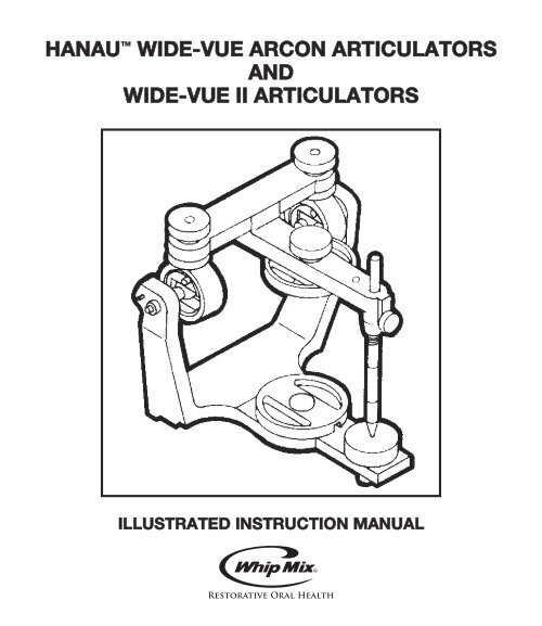
HANAU WIDE-VUE ARCON ARTICULATORS<br />
AND<br />
WIDE-VUE II ARTICULATORS<br />
ILLUSTRATED INSTRUCTION MANUAL
The HANAU Wide-Vue<br />
Series of Arcon Articulators<br />
INTRODUCTION<br />
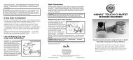
The HANAU Wide-Vue Articulators are classified as semi-adjustable. They are of Arcon principle,<br />
wherein the Condylar Guidances are associated with the Upper Articulator Member, as the patient’s glenoid<br />
fossa is a portion of the cranium, Figure 1.<br />
The Condyle of the Articulator is a part of the Lower Member <strong>and</strong> functions as the condyle of the<br />
patient’s m<strong>and</strong>ible.<br />
Articulator movements may be directly related to the anatomical function of the patient.<br />
Condylar Guidance<br />
<strong>and</strong><br />
Upper Member<br />
Condyle<br />
<strong>and</strong><br />
Lower Member<br />
ARCON PRINCIPLE<br />
1<br />
Glenoid Fossa<br />
<strong>and</strong><br />
Cranium<br />
Condyle<br />
<strong>and</strong><br />
M<strong>and</strong>ible<br />
FIG. 1
Kit Number 010882- 010885- 010898- 010889-<br />
000 000 000 000<br />
Mounting Plates 2 pair X X X X<br />
Orbital Indicator X X X X<br />
Dual End Incisal Pin X X X X<br />
Adjustable Incisal Guide X X X X<br />
Cond. Guide Protrusive/Retrusive Closed X<br />
Condylar Guidance Closed Track X X X<br />
Condylar Guidance Fixed Centric Stop X X X<br />
2
0˚<br />
-20˚<br />
Protrusive<br />
Inclination<br />
Protrusive<br />
Calibration<br />
+60˚<br />
Bennett<br />
Calibration<br />
Condylar<br />
Track<br />
Bennett<br />
Angle 30˚<br />
0˚<br />
CONDYLAR GUIDANCE FIG. 2 CONDYLAR GUIDANCE FIG. 3<br />
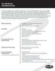
CONDYLAR GUIDANCE, Figure 2:<br />
The Condylar Guidances are the control centers of the Articulator <strong>and</strong> they adjustably assimilate the<br />
multiple function of the glenoid fossa.<br />
The Condylar Track may be adjustably inclined on the horizontal transverse axis from a “zero” to a plus<br />
60 degree or to a minus 20 degree. These inclinations are termed the protrusive inclination <strong>and</strong> simulate<br />
the patient’s superior wall of the fossa.<br />
The Condylar Track may also be adjusted on the vertical axis from a “zero” sagittal to 30˚. This angle<br />
is termed the progressive Bennett angle <strong>and</strong> corresponds to the medial wall of the patient’s fossa.<br />
CLOSED CONDYLAR TRACK, Figures 3 <strong>and</strong> 4:<br />
The Condylar Guidance Track of the Items in Footnote 2 rotates in an enclosed housing which stops<br />
the Condylar Element, preventing the accidental disengagement of the Upper Member.<br />
FIXED CENTRIC STOP, Figure 3:<br />
The Items in Footnote 3 have a Centric Stop at the posterior end of the Track to limit anterior movement<br />
of the Condylar Element. When the Element rests against the Stop it is at centric, the point from<br />
which the protrusive or Bennett angles both emanate.<br />
ADJUSTABLE PROTRUSIVE-RETRUSIVE, Figures 4 <strong>and</strong> 6:<br />
This feature is common to the items in Footnote 3. This micrometer adjustment permits the Condylar<br />
Element to be protruded 6 mm. from centric or to be retruded 3 mm. from centric.<br />
3<br />
Fixed<br />
Centric<br />
Stop<br />
Closed<br />
Track<br />
Centric<br />
Lock<br />
Centric<br />
Pin<br />
Condylar<br />
Element<br />
Condylar<br />
Guidance
See Footnote 1.<br />
Thumbscrew<br />
Reference<br />
Lines<br />
P-R<br />
Screw<br />
“Zero”<br />
Centric<br />
Line<br />
Sleeve<br />
3 mm<br />
Retrusion<br />
PROTRUSIVE-RETRUSIVE<br />
An axial reference line transcribes the one mm. spaced lines on the P-R Screw <strong>and</strong> a like line appears<br />
on the Sleeve of the Guidance.<br />
Loosen the Thumbscrew at medial side of the Guidance <strong>and</strong> rotate the P-R Screw to abut the <strong>wide</strong><br />
“zero” centric line with the Sleeve end. This centric position is then exactingly refined by aligning both<br />
axial lines as with a micrometer.<br />
Protrusion or retrusion of the Condylar Element can be fractionally adjusted by selective rotation of this<br />
P-R Screw. One full turn of the one millimeter pitch Screw equals 1 mm. protrusion or retrusion. 1 ⁄2 turn<br />
equals 1 ⁄2 mm., 1 ⁄4 turn equals 1 ⁄4 mm. <strong>and</strong> 1 ⁄8 turn equals 1 ⁄8 mm.<br />
This 1 ⁄8turn equals .005 inch <strong>and</strong> may be equated with a recognized dimension of the .004 inch (.1 mm.)<br />
thick U.S. dollar bill.<br />
Security of this adjustment is made by tightening the Thumbscrew lock at the medial of the guidance.<br />
The micrometer adjustment may be returned to this exacting centric position at any time.<br />
CENTRIC LOCK, Figures 3 <strong>and</strong> 4:<br />
Engagement of a Centric Lock depresses a Centric Pin, causing it to arrest the Condylar Element<br />
at the centric position. When locked, the Upper Member is restricted to an opening <strong>and</strong> closing<br />
movement only.<br />
Releasing the Centric Lock two full turns will disengage the Centric Pin <strong>and</strong> return the Element’s<br />
freedom of movement in the Condylar Track.<br />
4<br />
Centric Lock<br />
Condylar<br />
Element<br />
Closed<br />
Track<br />
Condyle<br />
Retainer<br />
Condylar<br />
Guidance<br />
6 mm<br />
Protrusion<br />
FIG. 4
At “Zero” Centric<br />
Bumper<br />
Setscrew<br />
Lower<br />
Member<br />
Condylar<br />
Shaft<br />
CONDYLAR SHAFTS<br />
AND BUMPER<br />
CONDYLAR SHAFTS, Figure 5:<br />
The Condylar Shafts adjustably slide in the “wings” of the Lower Member. They have been factory fixed<br />
by Setscrews when their brass shoulders rest against the flatted sides of the Condylar Elements at the<br />
“zero” centric position.<br />
A resilient Bumper will protectively stop the Upper Member <strong>and</strong> rest against the “Wing” of the Lower<br />
Member when fully opening the Articulator.<br />
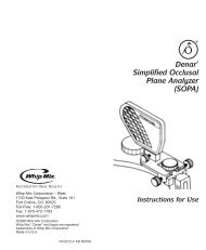
DUAL-END INCISAL PIN, Figures 6 <strong>and</strong> 7:<br />
Coinciding with these Condylar Shaft adjustments is an alignment of the chisel edge of the Incisal Pin<br />
with the central table of the Incisal Guide, Figure 7.<br />
The Incisal Pin serves as the forward control of the Articulator. It cooperatively maintains a vertical stop<br />
<strong>and</strong> provides a stylus contact for the excursive movements of the Articulator against the various inclined<br />
guiding surfaces of the Incisal Guide.<br />
A mid-line groove is cut in the Incisal Pin about one inch from the spherical tip. Five additional lines calibrated<br />
in millimeters extend on either side thereof. These lines are used for recording or altering the<br />
vertical dimension.<br />
5<br />
Upper<br />
Member<br />
Condylar<br />
Element<br />
Element at<br />
Shoulder<br />
Brass<br />
Shoulder<br />
“Wing”<br />
FIG. 5
Millimeter<br />
Calibrations<br />
Mid-line<br />
Flatted Side<br />
Chisel End<br />
Aligned With<br />
Central Table<br />
Upper Member<br />
Thumbscrew<br />
Dual-End<br />
Incisal Pin<br />
90˚<br />
DUAL-END INCISAL PIN FIG. 6 DUAL-END INCISAL PIN FIG. 7<br />
The Incisal Pin is inserted into, <strong>and</strong> the <strong>wide</strong>r mid-line of these metric grooves is aligned with, the top<br />
edge of the Upper Member. It is secured by the Thumbscrew bearing against the flatted side on the<br />
Pin. This adjustment places the chisel end at 90 degrees to <strong>and</strong> in contact with the central table of the<br />
Incisal Guide <strong>and</strong> provides a parallelism of the Upper Member to the Lower Member.<br />
Two annular grooves, Figure 7, appear on the Incisal Pin at 37 <strong>and</strong> 54 mm. below the Frankfort Horizontal<br />
Plane. These grooves form arbitrary vertical l<strong>and</strong>marks for alignment of the incisal edge of the maxillary<br />
centrals when making a Facebow transfer.<br />
The 37 mm. line is based in part on the Bonwil Triangle <strong>and</strong> results in a generally horizontal appearing<br />
plane of occlusion.<br />
The 54 mm. line forms an average l<strong>and</strong>mark for alignment of the incisal edge of the upper centrals when<br />
making a Facebow transfer. This reference line is based on the research study by Frank R. Lauciello,<br />
D.D.S., <strong>and</strong> Marc Appelbaum, D.D.S., “Anatomic Comparison to Arbitrary Reference Notch on Hanau <br />
Articulators,” Journal of Prosthetic Dentistry, December 1978, Volume 40, Number 6, Pages 676-681.<br />
The Incisal Pin extends beyond the top of the Upper Member <strong>and</strong> provides a third point of stability when<br />
inverting the Articulator for m<strong>and</strong>ibular cast mounting.<br />
The spherical tip of this Incisal Pin serves as the Dual-End <strong>and</strong> is useful for fabricating customized acrylic<br />
anterior guide tables. The procedural use of this is outlined on page 27.<br />
6<br />
Frankfort<br />
Horizontal<br />
Plane<br />
Inclined<br />
Occlusal Plane<br />
Horizontal<br />
Occlusal Plane<br />
37 mm. 54 mm.
Protrusive<br />
Inclination<br />
+60˚<br />
0˚<br />
-20˚<br />
Lateral<br />
Wings<br />
Thumbnut<br />
Thumbscrew<br />
Protrusive<br />
Calibration<br />
ADJUSTABLE<br />
INCISAL GUIDE<br />
Incisal Pin<br />
5.56 mm. Wide<br />
45˚ Lateral<br />
Inclination<br />
0˚<br />
Small<br />
Locknut<br />
Lateral<br />
Calibration<br />
0˚<br />
FIG. 8<br />
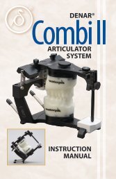
ADJUSTABLE INCISAL GUIDE, Figures 8 <strong>and</strong> 9:<br />
The Adjustable Incisal Guide provides an independent adjustment of anterior guidance. It cooperates<br />
with the Incisal Pin <strong>and</strong> Condylar Guidances to present a stable, three-dimensional programmed guide<br />
pattern for the mounted casts.<br />
The Incisal Guide rotates antero-posteriorly from a horizontal “zero” degree to a 60 degree positive<br />
inclination of protrusion which is then secured by the small Locknut. The central guiding table is<br />
5.56 mm. <strong>wide</strong> <strong>and</strong> forms the inclined surface for the protrusive guidance of the Incisal Pin.<br />
Separately adjustable Lateral Wings elevate by a Thumbscrew from a “zero” horizontal to a 45 degree<br />
incline <strong>and</strong> are fixed by a Thumbnut. The calibrations are very small <strong>and</strong> serve only as a reference.<br />
An anterior slot, Figure 9, in the Lower Member, allows repositioning of the Incisal Guide. Adjust <strong>and</strong><br />
lock the Guide at a “zero” horizontal <strong>and</strong> slightly loosen the Platform Lockscrew. Slide the Platform<br />
antero-posteriorly to align the chisel end of the Incisal Pin with the “zero” indicating line on the Lateral<br />
Wings.<br />
This adjustment will place the Incisal Pin contact on the rotational center of the Guide, thereby maintaining<br />
the vertical dimension when adjusting the inclination for protrusion.<br />
Loosening the Platform Lockscrew one turn will allow the Incisal Guide Assembly to be withdrawn from<br />
or returned to the anterior slot without any disassembly of parts.<br />
7<br />
“Zero”<br />
Indicating Line<br />
Platform<br />
Lockscrew<br />
ANTERIOR SLOT<br />
Small<br />
Locknut<br />
“Zero”<br />
Horizontal<br />
Incisal Pin<br />
Slide<br />
FIG. 9
Pointer of<br />
Facebow<br />
ORBITALE INDICATOR<br />
Additional anterior guidance tables may be optionally selected <strong>and</strong> their usage is detailed in latter<br />
portions of this book under:<br />
FLAT ANTERIOR GUIDE, Item Number 010741-000, Page 26, <strong>and</strong><br />
SCHUYLER LONG CENTRIC ADJUSTABLE INCISAL GUIDE, Item Number 010740-000, Page 29.<br />
Your selection of Tables shall determine the appropriate instructional reference.<br />
ORBBITALE INDICATOR, Figure 10:<br />
The Items in Footnote 1 are equipped with an Orbitale Indicator. This “crescent” represents the patient’s<br />
infra-orbitale notch <strong>and</strong> is the anterior reference l<strong>and</strong>mark of the Frankfort Horizontal Plane.<br />
When used with an Orbitale Pointer on a Facebow it provides an anatomical vertical orientation for the<br />
upper arch, obviating the use of any average reference lines on the Incisal Pin.<br />
8<br />
Orbitale<br />
Indicator<br />
FIG. 10
Dowel<br />
Hole<br />
Dowel<br />
ORBITALE INDICATOR<br />
MOUNTING PLATES, Figure 11:<br />
Mounting plates are used to lute the upper <strong>and</strong> lower casts to the Upper <strong>and</strong> Lower Articulator Members<br />
by the means of a gypsum material.<br />
These non-warping metal Plates contain two elongated <strong>and</strong> tapering luting slots for a secure adherence<br />
of the gypsum mounting. At their center is a domed brass insert which is internally threaded for<br />
attachment to the Upper or Lower Member. Longitudinally disposed to the luting slots <strong>and</strong> on the center<br />
plane of the insert is a keyway <strong>and</strong> a dowel hole which register over two Dowels in the Upper <strong>and</strong><br />
Lower Member.<br />
The Dowels cooperatively assist a threaded Thumbscrew which securely <strong>and</strong> accurately attaches the<br />
Mounting Plate. Order additional Plates as Item Number 005057-000, Mounting Plates, Pair (2).<br />
FACEBOW TRANSFERS<br />
These HANAU Wide-Vue Series of Articulators have the capability of accepting Facia (Snow) type or<br />
Earpiece type Facebow transfers.<br />
Substitutions of other HANAU Facebows may be made at your option:<br />
A. Facia type transfers using Facebows such as the HANAU Item Number 005702-000 or 005705-<br />
000 suspended from the ends of Condylar Shafts.<br />
B. Earpiece type Facebow transfers, particularly the HANAU 008824-000 suspend their Nylon<br />
Earpieces directly over the Auditory Pins which are 12 mm. posterior to the Condyle center.<br />
9<br />
Threaded<br />
Brass<br />
Insert<br />
Luting<br />
Slots<br />
Keyway<br />
Dowel<br />
Threaded<br />
Thumbscrew<br />
FIG. 11
Notched<br />
OCCLUSAL RIMS FIG. 12 BITEFORK PREPARATION FIG. 13<br />
OPERATORY PROCEDURE<br />
In principle, the outlined procedures in this book apply to all restorative dentistry with the casts <strong>and</strong> positional<br />
records of the natural dentition substituting for the edentulous casts, the denture bases <strong>and</strong> the<br />
occlusal rims.<br />
INTEROCCLUSAL RELATION RECORDS<br />
1. The maxillary <strong>and</strong> m<strong>and</strong>ibular occlusal rims have been prepared <strong>and</strong> patient adjusted to the correct<br />
vertical dimension, the occlusal plane <strong>and</strong> the desired horizontal overlap, Figure 12.<br />
The occlusal surfaces of both rims shall be appropriately notched to accept an interocclusal recording<br />
material such as softened wax or quick setting plaster.<br />
2. The top of the Bitefork or Biteplane, the stem at the patient’s left, is covered with a triple layer of baseplate<br />
wax, Figure 13. Heat seal the periphery <strong>and</strong> soften the wax throughout in a water bath.<br />
3. The softened wax impression material on the Bitefork is seated against the occlusal surface of the<br />
upper rim <strong>and</strong> is h<strong>and</strong> molded into <strong>and</strong> around the notches.<br />
Note that the stem of the Bitefork extends approximately parallel to the sagittal plane <strong>and</strong> is at the left<br />
of the patient.<br />
4. Chill the Bitefork index <strong>and</strong> check to assure removal <strong>and</strong> accurate replacement of the bite rim.<br />
5. The Bitefork may alternately be attached directly to the upper occlusal rim by heating the forks <strong>and</strong><br />
piercing them fully into the wax rim, Figure 14.<br />
The forks shall be parallel to the occlusal plane <strong>and</strong> shall not distort the occlusal or notched surfaces.<br />
10<br />
Wax Covered<br />
Molded to<br />
Occlusal Plane<br />
Stem at Left
Do Not<br />
Distort<br />
Occlusal<br />
Surface<br />
Pierced<br />
<strong>and</strong> Rigid<br />
Wax Rim<br />
Stem at<br />
Left<br />
ALTERNATE<br />
PATIENT INTEROCCLUSAL<br />
BITEFORK PREPARATION FIG. 14 RECORDS<br />
FIG. 15<br />
6. Two interocclusal positional records of a terminal relation are required, Figure 15.<br />
A centric interocclusal relation record is patient recorded at the vertical dimension of occlusion. The<br />
material is of choice but must be dead soft when recording <strong>and</strong> chill rapidly to an unyielding semi -<br />
brittleness –<strong>and</strong>–<br />
A protrusive interocclusal relation record is patient recorded at approximately 6 mm. anterior of centric.<br />
Closure is made to a near anterior, non-piercing occlusal contact, being certain that the bite<br />
rims remain securely seated on their ridges.<br />
LABORATORY PROCEDURE<br />
ARTICULATOR PREPARATION<br />
7. A. Adjust the protrusive inclination of both Condylar Guidances to 30 degrees <strong>and</strong> tighten the<br />
Thumbnuts, Figure 16.<br />
Note that the calibrations for these angles appear on both sides of the Guidance housing <strong>and</strong><br />
that the Right <strong>and</strong> Left can be seen <strong>and</strong> adjusted from the same side of the Articulator.<br />
B. Adjust the Bennett Angles of both Condylar Guidances at 30 degrees <strong>and</strong> tighten their thumbnuts.<br />
C. Adjust the Incisal Pin to align the mid-line calibration to the top edge of the Upper Member.<br />
D. Adjust the Incisal Guide to a “zero” degree <strong>and</strong> tighten the small Locknut.<br />
11<br />
Centric at Vertical<br />
Dimension<br />
Protrusive 6 mm.<br />
Anterior of Centric
Bennett<br />
Thumbnuts<br />
30˚ Protrusive<br />
Inclinations<br />
Condylar<br />
Guidances<br />
Protrusive<br />
Thumbnuts<br />
Centric Locks<br />
ARTICULATOR<br />
PREPARATION<br />
Micrometer Line<br />
“Zero” Centric<br />
Line <strong>and</strong><br />
Sleeve Edge<br />
30˚ Bennett<br />
Angles<br />
Platform Lockscrew<br />
Small Locknut<br />
Thumbscrew<br />
P-R Screw<br />
“Zero” Line Condylar<br />
Element<br />
Sleeve<br />
Contact<br />
Brass<br />
PROTRUSIVE-RETRUSIVE Shoulder<br />
E. Slide the Platform to align the Incisal Pin contact over the “zero” indicating line on Guidance<br />
<strong>and</strong> tighten Platform Lockscrew.<br />
F. Articulators with Protrusive-Retrusive feature ONLY: Items in Footnote 1 must be adjusted to a<br />
“zero” centric, Figure 17.<br />
12<br />
Centric Lock<br />
Mounting Plate<br />
Upper Member<br />
Mid-Line<br />
Registration<br />
Incisal<br />
Thumbscrew<br />
Incisal Pin<br />
Incisal Guide<br />
“Zero” Degree<br />
Allen Wrench<br />
Setscrew<br />
Condylar Shaft<br />
SLIDE<br />
FIG. 16<br />
FIG. 17
Release the Centric Locks <strong>and</strong> the Thumbscrews at the medial site of the Condylar Guidances.<br />
Adjust both P-R Screws to abut the “zero” centric line (<strong>wide</strong>st, most prominent <strong>and</strong> seventh<br />
from end) with the edge of the Sleeve. Refine this “zero” centric position by aligning the micrometer<br />
reference line on the P-R Screw with the “zero” line on the Sleeve.<br />
Secure the “zero” centric adjustment by tightening the Thumbscrews at the medial side.<br />
If the Articulator Condylar Shafts were adjusted on a previous case, they must be realigned to<br />
their original position.<br />
Loosen the two Setscrews with the Allen Wrench. Slide the Condylar Shafts to contact their brass<br />
shoulders with the flatted sides of the “zero” centric positioned Condylar Elements – without<br />
binding or perceptible side-shift.<br />
The chisel end of the Incisal Pin must exactly coincide with the central table of the Incisal<br />
Guide (reference Figure 6). Tighten the Setscrews to secure the Condylar Shafts in this position.<br />
G. Tighten the Centric Locks, Figure 16, to restrict the Articulator to opening <strong>and</strong> closing movements<br />
only.<br />
H. Apply a thin coating of petroleum jelly to all surfaces of the Articulator that will be exposed to the<br />
stone mounting media.<br />
I. Firmly attach a Mounting Plate to the Upper Member.<br />
Upper<br />
Member<br />
Lower<br />
Member<br />
Mounting<br />
Guide<br />
MAXILLARY ORIENTATION<br />
13<br />
Pivot<br />
Occlusal<br />
Index<br />
Bitefork<br />
Wrench<br />
Transfer Rod/<br />
Bitefork Index<br />
Assembly<br />
Socket<br />
Tapered<br />
Setscrew<br />
FIG. 18
Sticky Wax<br />
Spotted<br />
Maxillary<br />
Occlusal Rim<br />
Wetted Cast<br />
Surface<br />
Seated<br />
<strong>and</strong> Luted Incisal Pin<br />
Contact<br />
MOUNTING MAXILLARY CAST<br />
MOUNTING MAXILLARY CAST<br />
8. Swing the Upper Member of the Articulator OPEN to the Centric Bumper. Securely attach the<br />
Mounting Guide (furnished with the Twirl-Bow) to the Lower Member, Figure 18.<br />
9. Insert the lower end of the Transfer Rod/Bitefork Index assembly into the Socket of the Mounting<br />
Guide, aligning the Tapered Hole to accept the Tapered Setscrew in Socket. Tighten the Tapered<br />
Setscrew to enter <strong>and</strong> align the Transfer Rod.<br />
10. Raise the Pivot (cast support) to contact the underside of the Bitefork Index <strong>and</strong> lock in position by<br />
the Thumbscrew to stabilize <strong>and</strong> carry the weight of the maxillary cast <strong>and</strong> the stone mounting media.<br />
11. Securely seat <strong>and</strong> accurately lute the upper occlusal rim into the occlusal wax index on the Bitefork,<br />
Figure 19. The upper cast is then seated into <strong>and</strong> sticky wax spotted to the denture base.<br />
12. A mixture of stone is placed on the wetted mounting surface of the cast. The Upper Member is<br />
then swung forward to embed the Mounting Plate <strong>and</strong> to bring the Incisal Pin into contact with the<br />
Incisal Guide.<br />
The mounting is completed with a wet finger <strong>and</strong> spatula to expose the top surface of the Mounting<br />
Plate. This permits convenient removal <strong>and</strong> accurate reattachment of the cast to the Articulator.<br />
13. Upon complete set of the mounting, the sticky wax luting is carefully broken from the occlusal rim.<br />
The Mounting Guide <strong>and</strong> Transfer Rod/Bitefork Index assembly are removed from the Lower<br />
Member. Check that the occlusal rim is intact <strong>and</strong> that all of the sticky wax has been removed.<br />
14<br />
Embed<br />
Mounting<br />
Plate<br />
Stone<br />
Mounting<br />
Incisal<br />
Guide<br />
Incisal Pin<br />
FIG. 19
Mounting<br />
Plate<br />
Lower<br />
Member<br />
MOUNTING MANDIBULAR CAST<br />
Centric<br />
Record<br />
MOUNTING MANDIBULAR CAST, Figure 20:<br />
14. Invert the Articulator <strong>and</strong> swing the Lower Member back to the bench.<br />
Apply a thin coating of petroleum jelly to all surfaces of the Lower Member that may be contacted<br />
by the gypsum material.<br />
Firmly attach a Mounting Plate to the Lower Member.<br />
15. Securely seat the m<strong>and</strong>ibular cast in the bite rim <strong>and</strong> lute together with sticky wax.<br />
The centric interocclusal relation record is then carefully seated between the indexed occlusal<br />
surfaces of the upper <strong>and</strong> lower occlusal rims. Temporarily spot tack the occlusal rims in this<br />
centric position.<br />
16. A mix of stone is placed on the wetted mounting surface of the lower cast. The Lower Member is<br />
then swung over to embed the Mounting Plate into the stone <strong>and</strong> to bring the Incisal Pin into<br />
contact with the Incisal Guide.<br />
Complete the mounting with a spatula <strong>and</strong> finger, making certain that the Centric Locks have been<br />
secured.<br />
15<br />
Stone<br />
Mounting<br />
Wetted Cast<br />
Surface<br />
Sticky Wax<br />
Luted<br />
Mounted<br />
Maxillary<br />
Cast<br />
M<strong>and</strong>ibular<br />
Occlusal<br />
Rim<br />
Spot<br />
Tacked<br />
Maxillary<br />
Occlusal Rim<br />
FIG. 20
Thumbnuts for<br />
Horizontal Inclination<br />
Centric<br />
Locks<br />
Protrusive<br />
Record<br />
HORIZONTAL CONDYLAR INCLINATION<br />
ROTATE<br />
ADJUSTMENT OF HORIZONTAL CONDYLAR GUIDANCE, Figure 21:<br />
17. Upon complete set of the mount, the Articulator is placed into an upright position. Carefully cut<br />
the tacking at the occlusal surface <strong>and</strong> remove the centric interocclusal relation record.<br />
18. Loosen the Centric Locks <strong>and</strong> the Thumbnuts for horizontal inclination of the Condylar Guidances.<br />
Raise the Incisal Pin to remove the possibility of mechanical interference with the Incisal Guide.<br />
Whenever Centric Locks are loosened, the Condyle Retainers MUST be pushed outward to block<br />
the Track, barring accidental removal of the Upper Member.<br />
As a matter of habit, leave the Condyle Retainer closed except as necessary for required removal<br />
of Upper Member.<br />
19. Seat the protrusive interocclusal relation record onto the lower occlusal rim. Carefully guide the<br />
Upper Member into protrusion, lightly engaging the upper rim into the imprint of the protrusive relation<br />
record.<br />
Grasp the upper cast to maintain a tactile feel of the casts at the protrusive record <strong>and</strong> –<br />
20. Rotate the Right <strong>and</strong> Left Guidances back <strong>and</strong> forth to accurately seat the upper <strong>and</strong> lower rims<br />
into the protrusive relation record.<br />
Observe that the rims seat without rocking in or deforming the record <strong>and</strong> tighten the Thumbnuts<br />
for horizontal inclination. The protrusive relation record is then removed.<br />
16<br />
ROTATE<br />
Raised<br />
Incisal Pin<br />
Maxillary<br />
Cast<br />
FIG. 21
38˚ Protrusive<br />
Inclination<br />
Thumbnut<br />
38 +12=17˚<br />
8<br />
LATERAL<br />
INCISAL GUIDE<br />
CONDYLAR GUIDANCE FIG. 22 PREPARATION<br />
FIG. 23<br />
ADJUSTMENT OF LATERAL CONDYLAR GUIDANCE (BENNETT ANGLE), HANAU <br />
FORMULA, Figure 22:<br />
21. The classic HANAU Formula, L = H/8 + 12 may be used for adjusting the lateral condylar guidance.<br />
In this formula, “H” is the Horizontal Condylar (Protrusive) Inclination <strong>and</strong> “L” is the calculated<br />
lateral Condylar Guidance (Bennett Angle).<br />
EXAMPLE: The right protrusive inclination of 38 degrees is divided by 8 <strong>and</strong> is accepted as 5, to<br />
which 12 is added, totaling 17. The right Condylar Guidance is then adjusted to a 17 degree lateral<br />
indication at the calibration on the Upper Member <strong>and</strong> is locked by the Thumbnut.<br />
The same method is used for adjustment of the left lateral – dividing the protrusive inclination by<br />
8 <strong>and</strong> adding 12 – then setting the left Condylar Guidance to the computed angle.<br />
NOTE: An alternate method of Condylar Guidance adjustment utilizing lateral interocclusal relation<br />
records is described in a latter portion of this instruction, Steps 37 thru 44.<br />
Additional aids for establishing centric <strong>and</strong> lateral border movements are described under the<br />
“Optional Accessories” at the end of this instruction.<br />
ARRANGEMENT OF ANTERIOR TEETH<br />
22. The six upper <strong>and</strong> six lower teeth are set up in the arrangement dictated by the patient’s esthetic<br />
<strong>and</strong> phonetic requirements.<br />
17<br />
Thumbscrew<br />
Incisal Pin<br />
Contact<br />
“Zero” Line<br />
Small Locknut<br />
Lateral Wing<br />
“Zero” Horizontal
ROTATE<br />
Lingual of<br />
Maxillary to<br />
Incisal of<br />
M<strong>and</strong>ibular<br />
Straight<br />
Protrusion<br />
Incisal Pin<br />
Contact<br />
Small Locknut<br />
PROTRUSIVE FIG. 24 RIGHT LATERAL<br />
FIG. 27<br />
INCISAL GUIDE PREPARATION, Figure 23:<br />
23. Lock the Articulator into centric. The occlusal rims are then seated onto their casts at the established<br />
vertical <strong>and</strong> centric relation.<br />
24. Lower the Incisal Pin into contact with the “zero” horizontal Incisal Guide, the chisel end of the Pin<br />
resting crosswise on the center table <strong>and</strong> lock in position by the Thumbscrew.<br />
Verify or correct at this time, the alignment of the Incisal Pin chisel end with the “zero” indicating<br />
line on the Lateral Wings.<br />
Slightly loosen the small Locknut for protrusion <strong>and</strong> disengage the Centric Locks.<br />
ADJUSTMENT OF INCISAL GUIDE, Figures 24 thru 26:<br />
25. Gently guide the upper cast into a straight protrusion. The lingual edges of the upper central incisors<br />
are brought into contact with the incisal edges of the lower incisors, Figure 24.<br />
The Incisal Guide is then rotated antero posteriorly to make contact with the Incisal Pin, tightening<br />
the small Locknut to maintain the angulation.<br />
18<br />
Thumb<br />
Pressure<br />
Incisal<br />
Pin<br />
Contact<br />
Elevate<br />
Lateral<br />
Wing<br />
Locknut
Incisal<br />
Pin<br />
Contact<br />
Elevate<br />
Lateral<br />
Wing<br />
Locknut<br />
LEFT LATERAL<br />
Thumb<br />
Pressure<br />
26. The upper cast is then guided into a right lateral cuspid to cuspid guidance relation by thumb pressure<br />
at the right side of the upper cast to assure the Bennett Shift, Figure 25. The Lateral Wing is<br />
then elevated to contact the corner of the Incisal Pin <strong>and</strong> the Locknut is tightened to maintain this<br />
adjustment.<br />
27. Apply thumb pressure at the left side of the upper cast <strong>and</strong> guide it into a left lateral cuspid to<br />
cuspid excursion, Figure 26. Adjust the remaining Lateral Wing to contact the Incisal Pin <strong>and</strong><br />
secure the adjustment by tightening the Locknut.<br />
NOTE: Incisal Guide adjustment for natural dentition as in periodontic or orthodontic studies,<br />
occlusal correction, diagnosis, etc., are made in the same manner.<br />
19<br />
FIG. 26
Split<br />
Remounting<br />
Plates<br />
CAST REATTACHMENT<br />
ARRANGEMENT OF POSTERIOR TEETH<br />
28. The remaining teeth are set into centric occlusion <strong>and</strong> checked in working, balancing <strong>and</strong> protrusive<br />
excursions.<br />
The Incisal Pin acts as the vertical stop <strong>and</strong> must remain in contact with the Incisal Guide surfaces<br />
from centric throughout all excursive movements.<br />
29. The waxed occlusal rims may then be tried in the patient for esthetics, occlusal function <strong>and</strong> perhaps<br />
correction.<br />
The articulation is completed <strong>and</strong> the gingival <strong>and</strong> palatal is waxed.<br />
Reseat the completed occlusal rims onto their master casts. Seal the rims to the casts to preserve<br />
the tissue surface from plaster or stone seepage during the flasking procedure.<br />
PROCESSING<br />
30. Before removing the master casts/waxed dentures, record the Articulator calibrations for later use.<br />
Record the – Serial Number,<br />
R & L Horizontal Inclination,<br />
R & L Bennett Angle, <strong>and</strong><br />
Vertical of Incisal Pin<br />
20<br />
HANAU <br />
Mount<br />
Cat. No. 163-1<br />
Tapered Pin<br />
FIG. 27
REMOUNTING RECORD<br />
Plaster<br />
Occlusal<br />
Imprint<br />
Registration<br />
Keys<br />
Remounting<br />
Record Jig,<br />
Cat. No. 158-51<br />
31. If accessory HANAU Mount, Item Number 009750-000 or other methods of precise cast reattachment<br />
to the Articulator have been employed, the waxed dentures on their master casts are<br />
removed from their mountings <strong>and</strong> processed, Figure 27.<br />
ALTERNATE REMOUNTING RECORD<br />
32. Should no means have been provided for reattachment of the casts to the Articulator after denture<br />
processing, a “Remounting Record” is suggested. In lieu of this alternative is another Facebow<br />
transfer to effectively remount the processed upper denture <strong>and</strong> cast. It shall also be necessary to<br />
remount the lower into a centric occlusion.<br />
Remove the lower cast <strong>and</strong> attach the accessory HANAU Remounting Record Jig, Item No.<br />
009544-000, to the Lower Member as illustrated in Figure 30.<br />
Lubricate the index surface with petroleum jelly. Wrap boxing wax or masking tape around the<br />
periphery to form a dam in which to pour plaster sufficiently thick to register the upper occlusal imprint.<br />
Lock the Articulator in centric <strong>and</strong> lower the Upper Member to bring the Incisal Pin into contact<br />
with the Incisal Guide, <strong>and</strong> penetrating the upper occlusal cusps in the plaster.<br />
The waxed dentures on their master casts are then removed from their stone or plaster mountings<br />
<strong>and</strong> processed.<br />
21<br />
Boxing<br />
FIG. 28
REMOUNTING<br />
33. The completed dentures must remain seated on their master casts after processing <strong>and</strong> deflasking.<br />
If dislodged, they must be reseated properly <strong>and</strong> precisely.<br />
The master casts with their attached dentures are then accurately replaced on the original Articulator<br />
mountings using the Tapered Pin attachment of the HANAU Mount or by whatever means otherwise<br />
elected.<br />
34. If a “Remounting Record” has been made, Figure 28, the upper denture must be seated in the plaster<br />
occlusal imprint <strong>and</strong> the master cast remounted to the centric locked Upper Member of the<br />
Articulator.<br />
The lower complete denture must then be remounted to the Lower Member at a centric relation.<br />
CENTRIC OCCLUSION<br />
35. Verify or adjust the Articulator to the recorded calibrations for this denture case.<br />
With the dentures in place on their original Articulator mountings <strong>and</strong> the Articulator at centric, the<br />
Incisal Pin should be in an exact contact with the Incisal Guide.<br />
A space between the Incisal Pin <strong>and</strong> the Incisal Guide indicates that the vertical dimension has<br />
opened. The centric occlusion must be restored through the use of articulating paper <strong>and</strong> selective<br />
grinding. The vertical will be restored when the Incisal Pin again rests upon the Incisal Guide<br />
at a centric relation.<br />
Do not discount the possibility that the Incisal Pin may contact the Incisal Guide, but the teeth are<br />
not in occlusion. This would indicate a decrease in the vertical due to a processing error <strong>and</strong> the<br />
extent of closure <strong>and</strong> acceptability can only be determined by you. Release the Incisal Pin to<br />
occlude the dentures <strong>and</strong> retighten the Incisal Pin when it rests on the Incisal Guide.<br />
22
MILLING-IN<br />
WORKING SIDE BALANCING SIDE<br />
Contact<br />
Bennett<br />
Movement<br />
MILLING-IN<br />
36. When executing lateral excursions during the milling-in phase, it is essential that constant “toward<br />
the operator” pressure be exerted by the h<strong>and</strong> lightly holding the Incisal Pin or upper cast. This<br />
will insure that the shoulder of the Condylar Shaft, Figure 29, remains in contact with the flat of the<br />
balancing Condylar Element while the working Condylar Element rests against its centric stop <strong>and</strong><br />
slides later ally, thereby simulating the Bennett movement.<br />
ALTERNATE “CHECKBITE” TECHNIQUE<br />
ADJUSTMENT OF CONDYLAR GUIDANCES<br />
37. RIGHT <strong>and</strong> LEFT lateral interocclusal relation records may be elected to adjust the Condylar<br />
Guidances in lieu of a protrusive record <strong>and</strong> use of the HANAU Formula, Steps 18 thru 21.<br />
Concurrent with the patient recording of centric in Step 6 shall be a RIGHT <strong>and</strong> LEFT lateral inter -<br />
occlusal relation record in a material of your choice.<br />
Guide the patient into the softened recording material at approximately 4 to 5 mm. lateral of the<br />
midline. Assure that the lateral relation is devoid of any protrusion on the working side <strong>and</strong> that the<br />
bite rims remain securely seated on their ridges, without piercing the recording material.<br />
Chill the record, remove, trim <strong>and</strong> check the RIGHT <strong>and</strong> LEFT interocclusal records against the<br />
occlusal rims for an accurate <strong>and</strong> distortion free seating.<br />
23<br />
Bennett Angle<br />
Contact<br />
“Brass to Brass”<br />
FIG. 29
Raised<br />
Incisal<br />
Pin<br />
Thumbnuts for<br />
Bennett Angles Condylar<br />
Guidance<br />
ROTATE<br />
Thumbnuts<br />
for Condylar<br />
Inclination<br />
ADJUSTMENT OF LEFT CONDYLAR GUIDANCE, Figures 30 <strong>and</strong> 31<br />
38. Loosen the Centric Locks, the Thumbnuts for condylar inclination <strong>and</strong> Bennett Angles of both<br />
Condylar Guidances.<br />
Raise the Incisal Pin to eliminate possible interference with the Incisal Guide.<br />
39. Seat the RIGHT lateral interocclusal record onto the lower occlusal rim, Figure 30. Carefully guide<br />
the Upper Member into a right lateral, lightly engaging the upper rim onto the imprint in the seated<br />
RIGHT record.<br />
Grasp the upper cast to maintain an unstrained <strong>and</strong> tactile feel of the casts at this RIGHT lateral<br />
relation <strong>and</strong> –<br />
Slowly rotate the Left Condylar Guidance back <strong>and</strong> forth until the upper <strong>and</strong> lower rims seat into<br />
the lateral record.<br />
Observe that the rims seat without rocking in or deforming the record <strong>and</strong> tighten the Thumbnut<br />
for this condylar inclination.<br />
40. The lateral of this balancing Condylar Guidance is then slowly rotated from 30 degrees inward until<br />
the flat side of the Condylar Element contacts the shoulder on the Condylar Shaft, “brass to brass,”<br />
Figure 31. Tighten the Thumbnut to secure this left Bennett Angle.<br />
24<br />
Bennett<br />
Angle<br />
ROTATE<br />
Thumbnut<br />
Balancing<br />
Condylar<br />
Guidance<br />
Open<br />
Centric<br />
Locks<br />
“Brass to Brass”<br />
Element to Shoulder<br />
Right Lateral Upper Cast<br />
Record<br />
LEFT<br />
LEFT CONDYLAR INCLINATION FIG. 30 BENNETT ANGLE FIG. 31
Condylar<br />
Guidance<br />
Thumbnuts<br />
for Condylar<br />
Inclination<br />
Thumbnuts for<br />
Bennett Angles<br />
41. While still maintaining this lateral position in the record, slightly loosen the Thumbnut for condylar<br />
inclination, Figure 32, <strong>and</strong> reaffirm the record seating by slightly rotating back <strong>and</strong> forth, then<br />
retightening the Thumbnut.<br />
Remove the RIGHT lateral relation record.<br />
ADJUSTMENT OF RIGHT CONDYLAR GUIDANCE, Figures 32 <strong>and</strong> 33:<br />
42. Seat the LEFT lateral record on the lower occlusal rim, Figure 32. Guide the Upper Member into a<br />
left lateral, engaging the upper rim onto the record imprint.<br />
Grasp the upper cast lightly <strong>and</strong> then slowly rotate the Right Condylar Guidance to seat the rims<br />
into the lateral record. The rims must seat without rocking or deforming the record. Secure the<br />
Thumbnut for this Right Condylar Guidance inclination.<br />
43. The lateral of this non-working Condylar Guidance is then rotated inward from the 30 degree setting<br />
to contact the shoulder of the Condylar Shaft with the flat of the Condylar Element, again –<br />
“brass to brass,” Figure 35. Tighten the Thumbnut for this right Bennett Angle.<br />
44. While maintaining this left lateral cast position, slightly loosen the Thumbnut for condylar inclination,<br />
Figure 34. Check <strong>and</strong> perhaps refine the seating of the rims in the record <strong>and</strong> retighten the<br />
Thumbnut.<br />
Remove the LEFT lateral relation record.<br />
ROTATE<br />
Raised<br />
Incisal<br />
Pin<br />
25<br />
Thumbnut<br />
Balancing<br />
Condylar<br />
Guidance<br />
Bennett<br />
Angle<br />
Open<br />
Centric<br />
Locks<br />
“Brass to Brass”<br />
Element to Shoulder<br />
Upper Cast Left Lateral<br />
RIGHT<br />
Record<br />
RIGHT<br />
CONDYLAR INCLINATION FIG. 32 BENNETT ANGLE FIG. 33<br />
ROTATE
Polyvinyl<br />
Sheet<br />
FLAT ANTERIOR<br />
GUIDE PREPARATION<br />
ADDITIONAL OPTIONS<br />
FLAT ANTERIOR GUIDE<br />
The Flat Anterior Guide, Item Number 010741-000, is used as a flat, horizontal guidance table or as a<br />
disposable base for fabricating customized acrylic anterior guide tables.<br />
The Item Number 010741-000 consists of (1) Flat Plastic Anterior Table, Number 010294-000, <strong>and</strong> (1)<br />
Thumbscrew, Number 010717-000.<br />
The secondary purpose of the Dual-End Incisal Pin is for use with these Flat Anterior Guides. The Pin<br />
is reversed in the Upper Member with the spherical end in contact with the Flat Table.<br />
A fine grade of cold cure acrylic is suggested for customizing the Anterior Table, Item Number 3760.<br />
This is the final step of Articulator adjustment <strong>and</strong> no modification should be made to the Condylar<br />
Guidance settings or to the vertical dimension without also remaking the customized anterior incisal<br />
guidance.<br />
FLAT ANTERIOR GUIDE PREPARATION, Figure 34:<br />
A. Enter the two keys on the Anterior Table into the keyholes adjacent to the anterior slot <strong>and</strong> secure<br />
by the Thumbscrew.<br />
B. Carefully engage the Upper Member, bringing the casts into centric occlusion.<br />
26<br />
Incisal<br />
Thumbscrew<br />
Incisal<br />
Pin<br />
Anterior<br />
Table<br />
Thumbscrew<br />
FIG. 34
STRAIGHT<br />
PROTRUSIVE FIG. 35 RIGHT LATERAL<br />
FIG. 36<br />
C. Lower the spherical end of the Dual-End Incisal Pin into contact with the Anterior Table <strong>and</strong> tighten<br />
the Incisal Thumbscrew.<br />
D. Lubricate the spherical end of Pin with petroleum jelly.<br />
E. Place a 4” x 4” x approx. .0015” thick polyvinyl sheet between the upper <strong>and</strong> lower casts to resist<br />
abrasion of the stone cusps in natural dentition during the fabrication of the acrylic anterior guide.<br />
FABRICATION OF A CUSTOMIZED ACRYLIC ANTERIOR GUIDE<br />
HANAU Pantacrylic is mixed to a proportion of 2 ml. liquid <strong>and</strong> 6 gm. powder. Spatulate thoroughly<br />
to an almost putty consistency.<br />
Swing back the Upper Member <strong>and</strong> lay the putty-like Pantacrylic onto the DRY Anterior Table. Mound<br />
the acrylic about 3/8 - ” high at the center <strong>and</strong> do not overflow the edge.<br />
Five minutes after the start of mixing, the Upper Member is lowered to enter the Incisal Pin into the<br />
Pantacrylic. Immediately make excursions as described in A, B, <strong>and</strong> C below;<br />
The Incisal Pin must never be used to make lateral excursions from centric as to do so will negate the<br />
Bennett Shift <strong>and</strong> Bennett Angle, causing the working side Condyle to rotate only.<br />
A. Gently guide the upper cast into a full <strong>and</strong> straight protrusive by applying thumb pressure at the<br />
anterior of the upper cast <strong>and</strong> then promptly return to centric, Figure 35.<br />
B. From this centric relation, gently guide the upper cast into a full right lateral by thumb pressure at<br />
the right side of the cast to insure the Bennett Shift <strong>and</strong> then return to centric, Figure 36. The<br />
Bennett Angle on the nonworking side will be followed automatically.<br />
27<br />
Thumb<br />
Pressure
LEFT<br />
LATERAL<br />
C. The upper cast is then guided through a full left lateral excursion with its return then to centric,<br />
Figure 37. Thumb pressure at the left of the cast will allow full utilization of the Condylar Guidance<br />
settings.<br />
The Incisal Pin will be observed to displace the Pantacrylic <strong>and</strong> the three excursions from centric<br />
must be repeated as often as necessary until the material has set. Expected working time from mixing<br />
to a full set is approximately eight to ten minutes.<br />
Upon complete set of the Pantacrylic Incisal Guidance, the frontal area of the acrylic may be relieved<br />
with a carbide bur to permit free opening <strong>and</strong> closing of the Upper Member at a centric relation.<br />
Always apply thumb pressure at the side of the upper cast during laterals to insure the Bennett Shift<br />
o n<br />
the working side <strong>and</strong> the Bennett Angle on the nonworking. Pressure at the front of the cast will assure<br />
protrusion.<br />
Upon completion of the case, the Thumbscrew is removed <strong>and</strong> the customized Anterior Table filed with<br />
the patient’s casts <strong>and</strong> recordings – or it is discarded.<br />
A new disposable Flat Plastic Anterior Table is then attached for the next usage. Replacements are available<br />
as Item Number 009489-000, package of 12 disposable Flat Plastic Anterior Tables.<br />
28<br />
Thumb<br />
Pressure<br />
FIG. 37
“Zero” Contact<br />
Guide Table<br />
Horizontal<br />
Plane<br />
Adjustable<br />
Incisal Pin<br />
Platform<br />
Platform<br />
Lockscrew<br />
Flush<br />
Small<br />
Locknut<br />
LONG CENTRIC Screwdriver POINT OF<br />
PREPARATION FIG. 38 CENTRIC<br />
FIG. 39<br />
LONG CENTRIC ADJUSTABLE INCISAL GUIDE<br />
Dr. Clyde H. Schuyler’s Modification<br />
Another specialty guidance is the Long Centric Adjustable Incisal Guide, Item Number 010740-000. It<br />
provides an adjustable freedom of occlusal movement (LONG CENTRIC) in a centric relation position,<br />
thereby establishing an “area” of centric rather that a “point” of centric.<br />
It is suggested <strong>and</strong> described herein that the optionally available Adjustable Incisal Pin, Item Number<br />
010669-000, page 30, be used as it will maintain the adjusted LONG CENTRIC without having to reposition<br />
the Guidance Platform in the anterior slot.<br />
The st<strong>and</strong>ard Dual-End Incisal Pin may be used with LONG CENTRIC but the preciseness of adjustment<br />
will be compromised due to the Articulator arc of closure. Should this Pin be elected, it is then<br />
suggested that the LONG CENTRIC be overadjusted by perhaps 50 percent. A 1 mm. LONG CENTRIC<br />
would be adjusted to perhaps 1.5 mm. After re-establishing vertical by the Incisal Pin the LONG CEN-<br />
TRIC will reduce to perhaps 1 mm. Such an adjustment compensation may be satisfactory.<br />
A. Lower the Horizontal Plane below the Guide Table with a small screwdriver, inserted into the underside<br />
of small Locknut, Figure 38. Adjust the Incisal Guide to a “zero” degree <strong>and</strong> tighten the small<br />
Locknut.<br />
Slide the Platform in the anterior slot to align the angled Adjustable Incisal Pin contact with the<br />
“zero” line on the Guide Table. Securely tighten the Platform Lockscrew <strong>and</strong> do not disturb its<br />
adjustment throughout this LONG CENTRIC procedure.<br />
29<br />
Protrusive<br />
Point of<br />
Centric<br />
Horizontal<br />
Plane<br />
Adjustable<br />
Incisal Pin
Long<br />
Centric<br />
Adjustable<br />
Incisal Pin<br />
Boss<br />
Collar<br />
Incisal<br />
Thumbscrew<br />
Horizontal<br />
Plane<br />
Thumbscrew<br />
130-3013<br />
Mid-Line<br />
Calibration<br />
“Zero”<br />
Thumbnut<br />
Horizontal<br />
Platform<br />
Small<br />
Locknut<br />
Calibrated<br />
Angle Pin<br />
AREA OF<br />
ADJUSTABLE<br />
CENTRIC FIG. 40 INCISAL PIN<br />
FIG. 41<br />
B. The inclination of the Guide Table <strong>and</strong> the Lateral Wings are set to the dictates of the protrusion <strong>and</strong><br />
lateral guiding inclines of the anterior teeth, Figure 39. At this juncture we have the Adjustable Incisal<br />
Pin at the “point of centric.”<br />
C. To introduce the desired freedom of movement in centric (LONG CENTRIC), slightly “crack” the small<br />
Locknut <strong>and</strong> elevate the Horizontal Plane with a screwdriver until the amount of eccentric freedom of<br />
movement on the Horizontal Plane is obtained, Figure 40. Tighten the small Locknut, taking care that<br />
the incline has not been changed.<br />
It will be noted, upon return to centric, that this has opened the vertical dimension. The Adjustable Incisal<br />
Pin is then adjusted to re-establish the correct vertical dimension.<br />
In establishing or perfecting the occlusion of the complete denture or the occlusal rehabilitation of the natural<br />
dentition, the Incisal Pin must remain in functional contact with the Incisal Guide Table at all times for<br />
unrestricted freedom in centric.<br />
ADJUSTABLE INCISAL PIN<br />
This accessory Adjustable Incisal Pin (A.I.P.), Item Number 010670-000, allows the vertical dimension on<br />
the Articulator to be altered within a range of plus or minus 5 millimeter. It is the suggested companion to<br />
the Long Centric Adjustable Incisal Guide, Item Number 010740-000, described on page 29.<br />
The A.I.P., Figure 41, has been factory adjusted for this Wide-Vue Series of Articulators, the Collar having<br />
been fixed <strong>and</strong> shall not be disturbed.<br />
30
The Calibrated Angle Pin is adjusted by the Thumbnut to the mid-line calibration <strong>and</strong> then locked by<br />
the small Thumbscrew.<br />
Insert the A.I.P. into the Upper Member to contact the Collar with the Boss <strong>and</strong> tighten the Incisal<br />
Thumbscrew.<br />
This then is the ideal starting position for all usage <strong>and</strong> the Thumbnut is the only adjustable means –<br />
opening or closing the vertical 5mm. in either direction.<br />
The Platform of a “zero” horizontally adjusted Incisal Guide is repositioned to align the “zero” indicating<br />
line on the Lateral Wings with the contact point of the Calibrated Angle PIn.<br />
Always secure the Calibrated Angle Pin by the small Thumbscrew after any vertical adjustment.<br />
ARTICULATOR CARE AND MAINTENANCE<br />
Your <strong>Whip</strong> <strong>Mix</strong> articulator is a precision instrument <strong>and</strong> requires care <strong>and</strong> maintenance. Periodic<br />
cleaning <strong>and</strong> lubricating as described below will assure prolonged life <strong>and</strong> dependable service from the<br />
instrument. Failure to follow these instructions will void your warranty.<br />
CLEANING<br />
Use a mild soap <strong>and</strong> water solution with the aid of a brush to dissolve accumulations of wax <strong>and</strong> to<br />
wash away carborundum grit. Then air dry <strong>and</strong> lubricate. DO NOT use strong detergents, alkalies, gasoline<br />
or naphtha as cleaning agents.<br />
LUBRICATION<br />
Lubricate the working <strong>and</strong> bearing components with a thin film of sewing machine or high speed h<strong>and</strong>piece<br />
type oil. Wipe off excess oil to prevent accumulations of dust or grit.<br />
A thin coating of petroleum jelly must be applied to all Articulator surfaces that will be contacted by the<br />
gypsum mounting material.<br />
STORAGE<br />
Store the articulator in a clean, dry atmosphere free of plaster <strong>and</strong> carborundum dust; away from acids,<br />
alkalies or corrosive medicaments. Wait a full day after mounting casts before storing the articulator in<br />
a carrying case or corrugated carton. Moisture dissipation from the stone in an enclosed area causes<br />
alkalinity of the stone mixture which can damage the articulator surface.<br />
31
WARRANTY<br />
<strong>Whip</strong> <strong>Mix</strong> Corporation warrants the articulator system to be free from defects in material <strong>and</strong>/or workmanship<br />
for a period of one year. In the event of a defect, please notify the factory in writing of the defect<br />
prior to returning the instrument. <strong>Whip</strong> <strong>Mix</strong> Corporation will, at its option, either repair, replace or issue<br />
a credit for such defects.<br />
Because <strong>Whip</strong> <strong>Mix</strong> Corporation is continually advancing the design of its products <strong>and</strong> manufacturing<br />
methods, it reserves the right to improve, modify or discontinue products at any time, or to change specifications<br />
or prices without notice <strong>and</strong> without incurring obligations.<br />
32
FACEBOWS<br />
Besides the HANAU Spring-Bow, these<br />
Facebows may be preferred <strong>and</strong> are described<br />
fully in the Water Pik catalog:<br />
EARPIECE FACEBOWS:<br />
Item Number 008824-000 Earpiece Facebow<br />
with Orbitale Pointer <strong>and</strong> Bitefork; for use with<br />
010824-000, 010885-000, 010889-000.<br />
33<br />
FACIA (Snow Type) FACEBOWS:<br />
Item Number 005702-000 Facia Facebow<br />
with Bitefork; for use with 010812-000.<br />
Item Number 005705-000 Facia Facebow<br />
with Orbitale Pointer <strong>and</strong> Bitefork; for use<br />
with 010824-000, 010885-000, 010889-000.<br />
These Facebows include a Bitefork. To<br />
substitute a Biteplane for dentulous, specify<br />
“with Biteplane, Item Number 005727-000.”
FLAT ANTERIOR GUIDE,<br />
Item Number 010741-000<br />
Includes a quick indexing flat plastic Anterior<br />
Table <strong>and</strong> Thumbscrew for accurate repositioning<br />
on the Articulator.<br />
This flat plastic Anterior Table may also be<br />
used as a disposable carrier for fabricating a<br />
customized acrylic anterior guidance in an<br />
acrylic material.<br />
Replacement disposable Anterior Tables are<br />
available in packages of 12 as Item Number<br />
009489-000.<br />
34<br />
ADJUSTABLE INCISAL GUIDE,<br />
Item Number 010731-000<br />
This mechanical anterior guidance may be<br />
adjusted to the terminal inclines of protrusion<br />
<strong>and</strong> right <strong>and</strong> left lateral relations. It is used<br />
with the “chisel” end of the Dual-End Incisal<br />
Pin furnished with the Wide-Vue.
LONG CENTRIC ADJUSTABLE INCISAL<br />
GUIDE, Item Number 010740-000<br />
Provides an adjustable degree of freedom in<br />
centric relation, establishing an “area” of<br />
centric rather than a “point” of centric.<br />
It is recommended to be used harmoniously<br />
with the HANAU Adjustable Incisal Pin, Item<br />
Number 010670-000.<br />
ORBITALE INDICATOR,<br />
Item Number 005052-000<br />
Represents the patient’s infra-orbitale notch as<br />
an anatomical third reference point during a<br />
Facebow transfer to the Articulator.<br />
35<br />
ADJUSTABLE INCISAL PIN,<br />
Item Number 010670-000<br />
The vertical dimension may be altered within a<br />
range of plus or minus 5 millimeter while its<br />
Calibrated Angle Pin remains on the exact arc<br />
of Articulator closure.<br />
The ideal companion to the Long Centric<br />
Adjust able Incisal Guide, Item Number 010740-<br />
000.<br />
CAST SUPPORT, Item Number 003401-000<br />
Supports the Bitefork or Biteplane index during<br />
a Facebow transfer to the Articulator –<br />
preventing vertical displacement by cast weight<br />
<strong>and</strong> gypsum mounting.
REMOUNTING RECORD JIG,<br />
Item Number 009544-000<br />
Is used for the preparation of a permanent plaster<br />
record – accurately relocates the occlusal<br />
index for remounting the upper after processing.<br />
This precludes taking a second Facebow<br />
record <strong>and</strong> transfer to the Articulator.<br />
36<br />
BROADRICK OCCLUSAL PLANE<br />
ANALYZER, Item Number 006901-000<br />
Is used for analyzing the Curve of Spee <strong>and</strong> the<br />
Curve of Wilson in developing an acceptable<br />
curve of occlusion.
INSTRUMENT CASE, SMALL<br />
Item Number 015601-000<br />
This attractive <strong>and</strong> durable case has been constructed<br />
to contain the Articulator <strong>and</strong><br />
Facebow.<br />
It provides protective storage <strong>and</strong> transfer to<br />
or from the laboratory. Specify for Wide-Vue.<br />
37<br />
ALCOHOL TORCH<br />
Item Number 000301-000<br />
Is ideal for setting-up teeth, for waxing <strong>and</strong> for<br />
numerous other utility uses.
© 2008 <strong>Whip</strong> <strong>Mix</strong> Corporation.<br />
<strong>Whip</strong> <strong>Mix</strong> ® is a registered trademark <strong>and</strong><br />
Hanau is a trademark of <strong>Whip</strong> <strong>Mix</strong> Corporation.<br />
<strong>Whip</strong> <strong>Mix</strong> Corporation - West<br />
1730 East Prospect Rd., Suite 101<br />
Fort Collins, CO 80525<br />
Toll-Free: 1-800-201-7286<br />
Fax: 1-970-472-1793<br />
www.whipmix.com<br />
PN 33960-2 FN 339602-F AD R0308