Flat-Plate Microfiltration Membrane Bioreactor Designed - Treatment ...
Flat-Plate Microfiltration Membrane Bioreactor Designed - Treatment ...
Flat-Plate Microfiltration Membrane Bioreactor Designed - Treatment ...

You also want an ePaper? Increase the reach of your titles
YUMPU automatically turns print PDFs into web optimized ePapers that Google loves.
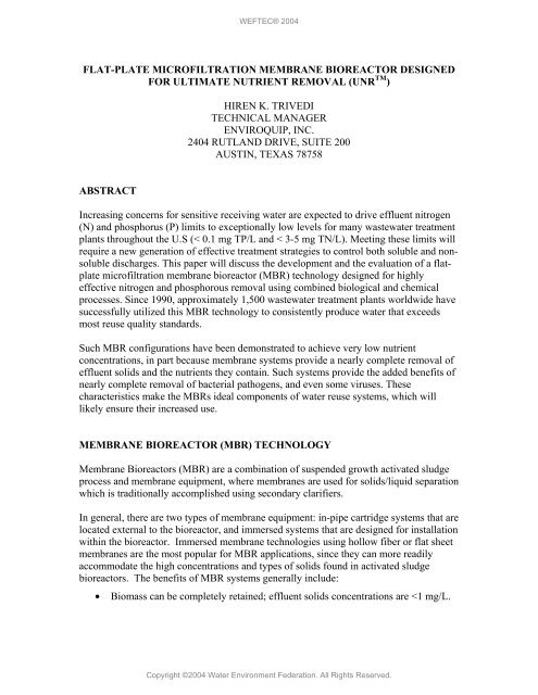
FLAT-PLATE MICROFILTRATION MEMBRANE BIOREACTOR DESIGNEDFOR ULTIMATE NUTRIENT REMOVAL (UNR TM )HIREN K. TRIVEDITECHNICAL MANAGERENVIROQUIP, INC.2404 RUTLAND DRIVE, SUITE 200AUSTIN, TEXAS 78758ABSTRACTIncreasing concerns for sensitive receiving water are expected to drive effluent nitrogen(N) and phosphorus (P) limits to exceptionally low levels for many wastewater treatmentplants throughout the U.S (< 0.1 mg TP/L and < 3-5 mg TN/L). Meeting these limits willrequire a new generation of effective treatment strategies to control both soluble and nonsolubledischarges. This paper will discuss the development and the evaluation of a flatplatemicrofiltration membrane bioreactor (MBR) technology designed for highlyeffective nitrogen and phosphorous removal using combined biological and chemicalprocesses. Since 1990, approximately 1,500 wastewater treatment plants worldwide havesuccessfully utilized this MBR technology to consistently produce water that exceedsmost reuse quality standards.Such MBR configurations have been demonstrated to achieve very low nutrientconcentrations, in part because membrane systems provide a nearly complete removal ofeffluent solids and the nutrients they contain. Such systems provide the added benefits ofnearly complete removal of bacterial pathogens, and even some viruses. Thesecharacteristics make the MBRs ideal components of water reuse systems, which willlikely ensure their increased use.MEMBRANE BIOREACTOR (MBR) TECHNOLOGY<strong>Membrane</strong> <strong>Bioreactor</strong>s (MBR) are a combination of suspended growth activated sludgeprocess and membrane equipment, where membranes are used for solids/liquid separationwhich is traditionally accomplished using secondary clarifiers.In general, there are two types of membrane equipment: in-pipe cartridge systems that arelocated external to the bioreactor, and immersed systems that are designed for installationwithin the bioreactor. Immersed membrane technologies using hollow fiber or flat sheetmembranes are the most popular for MBR applications, since they can more readilyaccommodate the high concentrations and types of solids found in activated sludgebioreactors. The benefits of MBR systems generally include:• Biomass can be completely retained; effluent solids concentrations are
• Long solids retention times can be achieved; sludge production is reduced as aresult.• Solids retention time can be reliably separated from hydraulic retention timeallowing independent control of both.• Secondary clarifiers and effluent filters can be eliminated, thereby reducing plantfootprint area.• Unlike clarifiers, the quality of solids separation is not dependent on the mixedliquor suspended solids (MLSS) concentration or characteristics. Since elevatedmixed liquor concentrations are possible, the aeration basin volume can bereduced, further reducing plant footprints.• Excellent effluent quality can be obtained.• Processes are easily automated; operator requirements are reduced.• A barrier against pathogens, such as the chlorine-resistant organisms,Cryptosporidium and Giardia, is provided.The primary applications for MBRs to date have been for facilities requiring waterquality for reuse, and/or facilities with significant land area restrictions.MEMBRANE FUNDAMENTALSIn broad terms, a membrane can be defined as an engineered semi-permeable barrier thatselectively allows the passage of some materials (e.g. water) while rejecting others (e.g.suspended solids). How readily one material passes through a membrane is defined asthe permeability of that material. For example, in wastewater applications, water willnormally have a high permeability while contaminants will have a low permeability. Thesize of particles rejected by membranes ranges from 0.0001 µm to 10 µm.It is important to note that, in wastewater applications, while the membranecharacteristics are important, a more important issue is development of biofilm on themembrane surface when exposed to activated sludge.There are several factors that can be used to further define or classify a membrane type.Classification factors include:• Pore characteristics such as size, orientation, density and surface charge• Primary separation mechanism (sieving, diffusion)• Driving force (pressure, osmosis)• Material of construction (organic, inorganic)Of these factors, pore characteristics have the most significant, or direct, impact on thefunctionality of a membrane. A pore can be described as a hole that penetrates the
In 2001, Enviroquip, Inc. of Austin, Texas partnered with Kubota to promote its MBRtechnology in the United States. Enviroquip is the exclusive licensee of Kubota MBRtechnology for US municipal/domestic wastewater treatment market. Enviroquip hasincorporated Kubota’s flat-plate membrane technology into their biological nitrogenremoval (SymBio ® Process) and biological phosphorous removal (EBPR) concepts. As aresult, a MBR process for achieving ultimate nutrient removal (UNR TM ) has beendeveloped.KUBOTA SMUThe Kubota SMU uses flat plate thin-film composite membranes manufacturedexclusively for use in wastewater treatment applications. Each sheet of membranematerial is made by dipping a non-woven mat of polyethylene terapthalate (PET) into asolution of chlorinated polyethylene and subsequently allowing the wetted mat to dry.During the drying process a thin membrane skin forms over the mat with a nominal poresize of 0.4 microns.Finished sheets of membrane material are cut to size and ultrasonically welded toacrylonitrile butadiene styrene (ABS) panels for mechanical support. This patentedultrasonic welding process is developed by Kubota specifically to provide a fail-safetriple bond between the ABS panel and the membrane itself. Inserted between themembrane and the panel is a polyester spacer material that serves as a plenum to evenlydistribute the permeate flow to channels cut into the panel. Each of the channels, orgrooves, terminates at a nozzle on top of the panel. The finished product is referred to asa membrane cartridge (Figure 1).FIGURE 1: A KUBOTA MEMBRANE CARTRIDGE.
Typical membrane cartridge dimensions are 19” x 39” x 0.25”. The total filtration areaper cartridge, including membranes on the both side of the plate, is approximately 8.6 sq.ft. Multiple cartridges (25-200) are inserted into cassettes and the cassettes in turnstacked on top of integral air diffuser cases. A clear plastic tube connects the nozzle ofeach cartridge to a permeate (filtered effluent) manifold that is connected to the permeateheader located outside of the MBR. The entire assembly, consisting of one or twomembrane cassettes and an air diffuser case, is referred to as a submerged membrane unitor SMU (Figure 2). Kubota membranes are designed to handle a wide range of mixedliquor (MLSS) concentration (e.g., 8,000 – 35,000 mg/L). This feature provides a uniqueadvantage for Enviroquip’s MBR technology in BNR applications over its competition.FIGURE 2: A SINGLE-DECK KUBOTA SMU.The engineered configuration of a Kubota SMU, and specifically the fixed verticalorientation of the cartridges, allow the diffused air to uniformly scour each membranesheet. In normal operation, equilibrium is established within seconds between thematerial being brought to the membrane surface through filtration and the material that isscoured away by the crossflow of mixed liquor (Figure 3). The result of this equilibriumis commonly referred to as a biofilm.If a cartridge were pulled out of service for examination, a typical biofilm would appearas a clear, thin slime layer covering the membrane surface and having a thickness on theorder of a few microns. Unlike other membrane applications (e.g. tertiary filtration), anymembrane submerged in a mixed liquor environment will be covered with this type ofbiofilm or cake layer. Moreover, it is the biofilm itself that does most of the filtrationmaking the membrane a secondary boundary between the mixed liquor and the filteredeffluent (the permeate).
capital cost. In general, smaller MBR plants (0.5 MGD utilize the double-deck SMU.FIGURE 4: KUBOTA DOUBLE-DECK SMU IN A MBR.As shown in Figure 5, air bubbles are emitted at the diffuser and channeledbetween each of the membrane cartridges as they rise to the surface. Thechanneled bubbles accomplish three important objectives: (1) provide adequateoxygen to maintain cell respiration at design MLSS, (2) scour the membranes toprevent fouling, and (3) create a pressure gradient between the top and bottom ofthe membrane unit.The pressure gradient created by the rising bubbles induces an upward cross-flowof mixed liquor over the membranes. The liquor is filtered as it flows across themembrane, due to the trans-membrane pressure gradient created by thehydrostatic head of the water above the membrane cassettes. The flux, or filterflowrate per area, is directly proportional to the trans-membrane pressure (TMP)gradient induced by the head of the water over the membranes (i.e. by the waterlevel in the tank). The TMP is roughly 0.7 psig during normal operation and 2psig at peak flow conditions (or prior to cleaning).
FIGURE 5: THE SCOURING EFFECT OF RECIRCULATING FLOW.On average, it is necessary to chemically clean Kubota membranes every three tosix months. The SMUs are cleaned in place quickly and efficiently by simplyinjecting, or pouring, a dilute solution of bleach or oxalic acid (0.5% typicalconcentration) into an accessible tee on the permeate suction line. The cleaningsolution remains inside the cartridges and soaks the membranes for about an hour,and then normal operation is resumed. For fouling due to organic substrates,bleach is recommended; and for inorganic fouling, oxalic acid should be used.During cleaning of one basin, the other basins are left online and operated at aslightly higher flux rate as required to meet plant’s flow demand.For municipal applications, 2-4 annual clean-in-place (CIP) procedures are typicallysufficient to maintain adequate permeability. This makes Enviroquip MBR plantsutilizing Kubota membranes, very easy to operate. Most Enviroquip MBR plants in theUS utilize semi-automated CIP systems. However the whole process can be easilyautomated for larger facilities. The key to keeping Kubota membranes clean is adequateand evenly distributed diffused aeration.ENVIROQUIP’S MBR SYSTEM CONFIGURATION FOR ULTIMATENUTRIENT REMOVALEnviroquip’s MBR system is designed to incorporate enhanced biological phosphateremoval (EBPR or Bio-P) along with total nitrogen removal. In a complete BNR plant,the raw, equalized influent wastewater is passed through a 1/8” screen first and is thenfed into an anaerobic tank. Typical hydraulic retention time (HRT) in the anaerobic tankis one hour based on the average design flow (Q). From the anaerobic tank, wastewater istransferred by gravity into an anoxic tank designed for denitrification. HRT in the anoxic
asin is based on the plant or the influent loading, the operating temperature, and thenitrogen removal requirements for the plant. From the anoxic tank, the wastewater isusually pumped to the membrane bioreactor (MBR). In cases where the influent loadingis high, a pre-aeration basin is recommended before the MBR in order to provideadditional biological treatment. The pre-aeration basin is usually maintained at lowdissolved oxygen (DO) levels below 1.0 mg/L for simultaneous nitrification anddenitrification (utilizing Enviroquip’s SymBio ® Process). The MBR is maintained underaerobic conditions at DO > 1.0 mg/L.If a pre-aeration basin is needed, wastewater is pumped from the anoxic basin to the preaerationbasin and is fed from the pre-aeration basin to the MBR by gravity. The mixedliquor is recycled back to the anoxic basin from the MBR by gravity to complete therecycle loop. Typical recycle from the MBR to the anoxic basin is 2Q-4Q which means3Q-5Q is pumped from the anoxic basin either to the pre-aeration basin or to the MBR. Incases where EBPR is needed, an additional 1Q-2Q is fed back to the anaerobic basin (bygravity) from the SymBio ® pre-aeration basin or is pumped from the anoxic basin (Figure6). For achieving total nitrogen values below 3.0 mg/L, usually a post-anoxic basin isalso included. Supplemental carbon addition is recommended in the post-anoxic basin toensure complete denitrification. Typical plant HRT in this configuration is in range of 5-8hours. The operating mixed liquor (MLSS) concentration ranges between 10,000 mg/land 18,000 mg/L. The ability of Kubota membranes to handle a wide range of mixedliquor allows operators to maintain higher than the required biomass inventory in plantsfacing low flow or low loading conditions. This flexibility of operation helps in avoidinghigh DO concentration in recycle streams (due to higher cell respiration requirements)and maintain an efficient BNR process.FIGURE 6: ENVIROQUIP’S MBR PLANT FOR UNR TMChemical1-2QChemicalQANDO=0 ppmHRT=1 hrAXDO=0 ppmHRT=1.5 hrSNdNDO1 ppmHRT=2 hrQ>2QBIOLOGICAL NITROGEN REMOVALFor applications within the United States, Enviroquip has coupled its proprietarySymBio ® technology for simultaneous nitrification and denitrification (SNdN) with theMBR technology. This combination is proposed for plants designed to meet stringent
nutrient removal requirements such as 3-5 ppm TN. Low total nitrogen levels areachieved by using a simultaneous nitrification and denitrification concept in conjunctionwith the conventional concept of recycle to a pre-anoxic basin from the MBR. Use of theSymBio ® process results in lower aeration energy consumption for the MBR process andalso lowers the internal recycle requirement for denitrification to the anoxic zones.ENVIROQUIP’S SYMBIO ® PROCESSThe SymBio ® process monitors the NADH (nicotinamide adenine dinucleotide) levels inthe biomass, along with dissolved oxygen levels in the water, to indicate the changingbiological oxygen demand very precisely. Based on the results, the aeration is controlledto maintain low dissolved oxygen (< 1.0 ppm) to facilitate simultaneous nitrification anddenitrification in the same (e.g., pre-aeration) basin. This award winning technology hasbeen utilized successfully all over the world by the wastewater treatment industry.The low DO operation in the SymBio ® process creates a dual-zone phenomenon withineach sludge floc (Figure 7). The outer fraction of the biofloc is exposed to a relativelyhigher DO concentration and hence is considered aerobic. Nitrification of ammonia tonitrate occurs in this outer fraction of the floc. Towards the center of the floc, DO isdepleted quickly and anoxic conditions prevail due to the presence of nitrate.Denitrification is the dominant reaction in the interior fraction of the floc. Hence totalnitrogen removal is achieved in a single reactor with simultaneous nitrification anddenitrification. The SymBio ® process allows existing, as well as new WWTPs, to meetthe most stringent requirements for nitrogen control.The objective in the SymBio ® process is to monitor and control the biological activity inthe aeration basin. Instead of monitoring only conventional parameters like DO, pH, ORPor alkalinity (all of which are free water phase parameters and are result of biologicalactivity), the SymBio ® process also monitors a direct biological parameter using afluorescence signal. This fluorescence signal is generated by monitoring a coenzymecalled NADH (nicotinamide adenine dinucleotide), which is active within each bacteriacell. This coenzyme is present in all living microorganisms. It has a unique property that,when struck with an ultraviolet light at 340 nm, it fluoresces back at 460 nm. Further, theconcentration of NADH in each cell (and hence cumulatively in each floc) changes withthe metabolic state of the cell. For example, under anaerobic conditions (or high organicloading and low DO conditions) the concentration of NADH tends to be high in thebiomass/activated sludge, resulting in a higher fluorescence signal. In contrast, underaerobic conditions (DO > 2.0 ppm) the NADH level tends to be low, generating a veryweak signal (Figure 8). The fluorescence signal under anoxic conditions is usuallybetween these two extreme cases.The SymBio ® sensor sends a UV light at 340 nm and detects the light emitted fromNADH at 460 nm. The signal is converted to an analog output (4-20 mA) and along witha separate 4-20 mA analog output from a conventional DO sensor, it is used to control the
air flow from the blower via a PLC. If the NADH signal indicates higher than normalvalue under any given situation due to lack of DO for the biomass, the air flow isautomatically increased. The NADH/DO monitoring provides an effective tool for strictaeration control to maintain simultaneous nitrification / denitrification conditions withineach floc.It has been established that the SymBio ® process control technique can allow operators tofine tune the plant operation in such a way, that the interior fraction of the floc is allowedto go anaerobic for a short-duration by monitoring NADH level in the biomass and thenincreasing the air supply to avoid septic condition from developing. This feature createsan environment for enhanced biological phosphate uptake in the same tank. Plantsoperating under SymBio ® mode can expect higher than normal phosphorous content inthe waste sludge, thus reducing any chemical requirements (Figure 7).FIGURE 7: ENVIROQUIP’S SYMBIO ® PROCESS-LOW DO OPERATIONThe SymBio ® Process – SNdN and Bio-Pby monitoring NADH FluorescenceCO 2OX zone vPromote Partialv1EBPRAN ZONE v COv2• ControlledanaerobicOxygen AX ZONE4N 2conditions2• US Patent:3Ammonia6,712,970OrganicOxygenmatterDO concentration gradients can create anoxic andanaerobic zones within sludge flocsFIGURE 8: ENVIROQUIP’S SYMBIO ® PROCESS-AERATION CONTROLThe SymBio ® ProcessProportional Aeration ControlBioflocDecreasing oxygen concentrationIncreasing organic loadNADH fluorescence increasesSymBio ® FlocAerobic partAnoxic centerIncreasing oxygen concentrationDecreasing organic loadNADH fluorescence decreases
For a wastewater treatment plant handling 2 million gallons per day of typical domesticwaste, the following table provides the chemical dose requirement for achieving variouseffluent phosphorous levels (Stensel, 2003). Two options for P removal are considered:• Chemical precipitation only• EBPR combined with chemical precipitationIt is assumed that the inlet P concentration is 8 mg/L and EBPR alone can reduce the TPconcentration to 1.0 mg/L in the effluent. The chemical to be added is assumed to beAlum. Eleven lbs. of commercially available Alum is required to provide one lb. ofaluminum.TABLE 1: ALUM REQUIREMENTS (IN LBS.) REDUCES WITH EBPREffluentRequirement1.0 mg/LChemicaladditiononly1920EBPR withchemical inanaerobic-EBPR withchemical inaerobic-0.5 mg/L29401603500.1 mg/L5110160640It seems that adding chemicals in the anaerobic zone may be the most cost-effectivesolution. However there is an inherent risk of washing out PAOs over long term due to alack of available phosphorous for uptake in the aerobic zones.Kubota’s own research has established a chemical addition requirements to achievedifferent effluent phosphorous levels for typical municipal/domestics wastes (Table 2). Itappears that flat plate microfiltration membranes requires less chemicals to removephosphorous to low levels (< 0.1 mg/L), (due to complete removal of suspended matters),compared to conventional activated sludge plants which rely on gravity separation ofsolids from the treated water.
TABLE 2: CHEMICAL (AL SALT) DOSE VERSUS EFFLUENT TPCONCENTRATION FOR ENVIROQUIP’S MBREffluent Pconc. mg/L0.050.100.50Al/P ratioM/M2.62.01.0Run Time,days4 weeks3 weeksLong termENERGY EFFICIENCY WITH ENVIROQUIP MBR SYSTEMEnviroquip realizes that along with fouling control and relatively a maintenance freeoperation, energy efficiency is also critical for MBR technology. As a result, Enviroquiphas made great efforts in reducing the overall energy consumption for a MBR plantthrough product development and process optimization. The following improvementshave been incorporated to improve the energy efficiency:• Use SymBio ® process to reduce the aeration energy requirements in the preaerationbasin.• Use reduced recycle flows to the anoxic zones during operation because ofsimultaneous denitrification in the pre-aeration basin.• Maintain normal operating MLSS concentration at 10,000 mg/L verses 15,000mg/L or higher, in order to improve aeration transfer efficiency (through better αvalues).• Use double-deck SMU units for larger plant (> 0.5 MGD) to reduce themembrane scouring aeration requirements.FIGURE 10: IMPROVED ENERGY EFFICIENCY FOR ENVIROQUIP’S MBRSYSTEMSRT33%SNdN34%SMU33%Total Power ↓≅50%• Double-Deck SMU• Scour air ↓ 26%• Reduced SRT/MLSS• Endogenous O2 ↓• Alpha ↑• SymBio ® SNdN• OTE ↑162HP/MG → 79HP/MG(INFLUENT: 225/225/35:BOD5/TSS/TKN)
CASE STUDIESTHE RUNNING SPRINGS WATER RECYCLING PLANT, CAFIGURE 11: FIRST FULL-SCALE MBR PLANT IN NORTH AMERICAINCORPORATING SYMBIO ® PROCESS CONTROL AND EBPRHIGHLIGHTSPoints of Interest Description NotesLocationRunning Springs,CALocated in Big Bear NationalParkProcess Configuration MBR Enviroquip UNR Process<strong>Membrane</strong> EquipmentConfigurationDouble-Deck <strong>Flat</strong><strong>Plate</strong>Kubota Submerged<strong>Membrane</strong> Units (SMU)Permit Type Reuse Issued by Department ofForestryDesign Flow/Peak Factor 0.6 MGD/2 24-hr Peak FactorUnique FeaturesGravity OperationSymBio ® ProcessControl in the MBRRetrofit projectBNR ProcessBACKGROUNDThe Running Springs, CA County Water District currently operates a wastewatertreatment plant that discharges to subsurface infiltration ponds and a small stream, bothof which fall under the juridiction of the US Forest Service. In 2002, the District was
informed their permit would soon expire and that the new permit would include strictlimits on nitrogen and phosphorus.To address the impending nutrient limits, the District intially tried increasing the plantsludge age by increasing the operating mixed liquor (MLSS) concentration in the aerationtanks. However, the existing rectangular secondary clarifiers could not handle theincreased loading and the District had to explore other options. In 2003, the Districtbegan converting the existing facility into a MBR system.Starting in April of 2003, the plant was retrofited with Enviroquip’s MBR systemincluding the SymBio ® process for SNdN as well as enhanced biological phosphorusremoval (EBPR) concept by converting exisitng clarifiers and aeration basins. BySeptember the plant was completely converted and optimized to meet future nutrientlimits.PROCESS OVERVIEWAs the diagram in Figure 11 indicates, the flow schematic is similar to an A 2 O TM processwith the exception that membranes are used for filtration and the aerobic portion of theplant is operated at low dissolved oxygen content with the SymBio ® process control topromote simultaneous nitrification/denitrification (SNdN).Raw wastewater enters the plant at a fine screen to remove particles greater than 1/8” indiameter. The screened influent is then degritted in an aerated grit chamber before beingfed to the pre-anoxic (DeOX/AX) Basin.Mixed liquor, containing phosphorus accumulating organisms (PAOs), overflows into theAnaerobic/Anoxic Basin (AN/AX) for removal of any remaining nitrates and to facilitateEBPR. The AN/AX Basin side water depth varies to partially equalize flow and to allowfor optimization of membrane performance. In other words, membrane filtration rate orflux is automatically adjusted to match influent flowrate by monitoring the level in theAN/AX Basin. As the level increases so does the flux, until a peak flow of 1.2 MGD isreached.Submersible pumps continuously recycle mixed liquor to the aerated part of the MBRs atroughly four times design flow or 2.5 MGD. Whatever is not filtered by the membranesreturns to the DeOX/AX Basin as thickened sludge, to complete an internal recycle loop.Each MBR contains eight double-deck Kubota submerged membrane units and finebubblediffusers. The fine-bubble aeration system is used to supplement the processoxygen demand and control the dissolved oxygen concentration.Utilizing NADH and DO signals, the SymBio ® process controller automatically adjuststhe speed of a dedicated blower to keep the DO concentration in the MBRs between 0.2
and 0.8 mg/l. This ensures SNdN in the basins. Filtered water (permeate) can be furtherdisinfected using ultraviolet (UV) light.To control sludge age, mixed liquor is periodically wasted from the system and pressedbefore disposal. Filtrate is returned to the head of the plant for treatment.FIGURE 12: THE RUNNING SPRINGS, CA MBR PFDMBR 1SymBioAN/AX DeOX/AXMBR 2SymBioINFLUENTThe MBR Basins are components of the MBR process and are often referred to asmembrane basins. Similarly, the Pre-Aeration (PA) zones can also be called simplyAeration Zones in plants with similar PFDs.SOURCE WATER QUALITYThe Running Springs WRF treats the wastewater from the town of Running Springs,several campsites and ski lodges. From startup, influent flowrates have averaged 0.6MGD with instantaneous peaks reaching 1.5 MGD. The wastewater has a fairly typicalprofile with the exception of an inordinately high phosphorus concentration. The sourceof the high phosphorus concentration is unknown at this time.Data collected during process optimization indicates that the system is capable ofbiologically reducing nitrogen and phosphorus concentrations to meet impending permitlimits. According to the US Forestry Department, the new permit will include limits of5/5/2 as BOD/TIN/P. Chemical addition will be required to further reduce phosphorusconcentrations given the unusually high load coming into the plant.OPERATOR HIGHLIGHTS1. Monitoring NADH allows for process optimization beyond DO control. DOprobes register changes in water phase concentrations but do not reflect biologicalactivity. On several occasions, DO setpoints and aeration cycles were changed
ased on changes in the NADH signal in order to track variable organic load andchanges in SRT.2. Phosphorus re-release at higher sludge ages (>43 days) has not been significant.Also, treating supernatant from the pressing operation has not impacted biologicalphosphorus removal. Apparent sludge phosphorus content has been as high 8%by weight phosphorus.TABLE 3: AVERAGE INFLUENT AND EFFLUENT WATER QUALITY FORTHE RUNNING SPRINGS WRFParameterCBOD 5 (mg/l)TKN (mg/l)InfluentDesignValue26036ActualInfluentData(Mean)22341ActualEffluentData(Mean)00NotesNitrate (mg/l)TN (mg/l)TP (mg/l)Turbidity (NTU)0NA8NA041153.9< 4.04.9< 0.1SymBio ® in MBR +2Q recycleEstimated based onTKN, Nitrate andNitrite valuesNo ChemicalAdditionADF (mgd)0.60.60.6Full flow onceMBR2 came onlineTHE HAMPTONS WRF, GAFIGURE 13: ENVIROQUIP’S MBR PLANT AT THE HAMPTON CREEK WRF,GA
BACKGROUNDIn years past, water reclamation facilities have been typically located within or in veryclose proximity to a WWTP sited on the fringes of urban areas. In some cases, potentialusers of reclaimed water could be found in the vicinity, but in most cases, expensivetransmission systems were required to convey the reclaimed water to the end users,making reuse difficult to justify economically.To address this problem, satellite reclamation is a new concept that involves theinstallation of MBR facilities as "scalping" facilities, sometimes referred to as "sewermining" to reclaim water locally for reuse. By putting smaller plants out in the remoteareas near the collection system and close to the reuse site, the costs of installingdistribution systems to take reclaimed water from the main plant back out to the reuseareas can be avoided. This relocation will also reduce the pumping costs, as most centralplants are located at the low point in the system.The Hamptons Water Recycle Facility (WRF) was constructed to provide the necessaryutility service to a large planned development and to supplement the Forsyth Countyservice area. Within the 514-acre development are a championship golf course and a480-unit subdivision.HaThe effluent from this facility is used for irrigation at the golf course, residential homesand other green spaces within the development.FIGURE 14: HAMPTON CREEK WRF MBR PFDAX2MBR4Q4-6QAN2MBR3AN1MBR2ANP1MBRAX1MBR1AX– Two trains, four MBRs– Anoxic/Aerobic complete mix activated sludgewith space available for Anaerobic Zone (EBPR)– Process objectives
County and adjacent developments. From startup, influent flowrates have rangedbetween 0.05 to 0.10 MGD. As a result, only one of the four MBRs are currently online.The plant was designed to allow for expansion by installing additional membrane units asnew users come online. The owner expects additional reactors to be brought onlinewithin the next year.The wastewater contaminant concentrations are higher than typical municipal numbersdue to the food service contribution and the new conveyance infrastructure.Data collected through February 2004 indicate that the system is capable of easilymeeting current permit limits and addressing future nutrient limits. According to theGeorgia DEP, future permit requirements may include a phosphorus limit of
2. Building in multiple process trains allows for easy expansion to meet futuredemands without building in membrane capacity initially.HIRAKATA APARTMENT COMPLEX, JAPANKubota provided a MBR system for an apartment complex in Japan. The plant capacitywas rated up to 35,600 gallons/day. In 1999, they demonstrated the effectiveness of flatplatemembrane in precipitating phosphorous by addition of iron and aluminum salts. Theresults are provided below.FIGURE 15: HIRAKATA, JAPAN MBR PFDCoarse Screen Aerated Grit EqualizationMAerobicAnoxicDisinfectEffluentFine ScreenFeSO 4 (M/M)Sludge DisposalTABLE 5: HIRAKATA, JAPAN MBR DESIGN INFORMATIONMBR System DesignUnitEqualizationAnoxic TankAerobic Tank<strong>Membrane</strong>fluxDisinfect TankParameterEquiv. HRTEquiv. HRTEquiv. HRTL/m 2 -hrminValue9 hours9.4 hours7.7 hours2125
TABLE 6: HIRAKATA, JAPAN INFLUENT AND EFFLUENT QUALITY DATAItemMLSSP in ,1999 Certification Inspection Results, mg/L*Ferric after March 2, 1999EBPR + Chemical Precipitation occurringMar. 2*14,0004.1Mar 3116,0004.4Apr 814,0003.7Apr 1517,0004.6Apr 2218,0004.5P out ,0.470.070.050.050.01BOD in 200210150185180BOD out
POINT LOMA, CAIn October 2001, the City of San Diego and Montgomery Watson Harza (MWH) wereawarded a grant from the Bureau of Reclamation to evaluate MBR technology and itspotential application to wastewater reclamation. Earlier, in March 2000, this project teamhad worked with the California Department of Health Services (DHS) to establish criteriafor MBR systems for meeting California Title 22 Water Recycling Standards.Accordingly, a testing protocol was developed which consisted of evaluating long-termoperational performance and virus rejection. Enviroquip/Kubota MBR technology wasevaluated for Title 22 approval in 2002. A pilot plant rated at 25,000-gallons/day capacitywas used for the study.During the main study investigating the performance of the Enviroquip/Kubota MBR, thesystem was operated on both raw wastewater and advanced primary effluent from thePoint Loma Wastewater <strong>Treatment</strong> Plant (PLWTP) in San Diego, CA. Table 7 showswater quality data collected from these two sources during the study. The primarytreatment process at the PLWTP includes influent screening, grit removal, coagulationand sedimentation. The virus seeding experiments were conducted using advancedprimary effluent and clean water.As the results from the study in Table 9 and 10 indicate, the Enviroquip/Kubota systemwas capable of providing high quality effluent water consistently.TABLE 7: RAW WASTEWATER AND ADVANCED PRIMARY EFFLUENTQUALITY DURING BUREAU OF RECLAMATION PILOT STUDYParameters Units Raw Wastewater Primary EffluentAmmonia-N mg/L 27.4 26.6Nitrite/Nitrate-N mg/L 0.55 0.789Nitrate-N mg/L 0.005 0.026Orthophosphate-P mg/L 0.724 0.455BOD 5 mg/L 231 96.9COD mg/L 528 216TOC mg/L 40 44TSS mg/L 113 44Calcium Hardness mg/L 248 186Magnesium Hardness mg/L 292 207Total Hardness mg/L 546 392.5TABLE 8: ENVIROQUIP/KUBOTA PILOT PLANT DESIGNParametersAnoxic HRTPre-aeration HRTAerobic <strong>Membrane</strong> HRTTotal HRTValues1.6 hours0.6 hours2.5 hours4.7 hours
MLSSSRTTemperature10,000 mg/L12-15 days25-30 o CTABLE 9: BIOLOGICAL NITROGEN REMOVALPercentile Influent Ammonia-N, mg/L Effluent TIN, mg/L99% 30 790% 29 450% 28 3TABLE 10: SUMMARY OF RESULTS FROM POINT LOMA, CA STUDY•Title 22 Approval from DHS, CA• BOD < 2 ppm (all samples)• Turbidity < 0.2 NTU (all samples)• TIN < 4 ppm (90% of the sample)• Total Coliform > 5-6 log removal (95%)• Fecal Coliform > 5-log removal (100%)• Total Coliphage > 3-log removal (80%)It is important to note that, during the 2 nd phase of the study performed by MWH at LosAngeles County Sanitation District, CA, the Enviroquip/Kubota MBR system was shownto handle a peak flux of 42 gfd while meeting the Title 22 turbidity performance criteria.Based on the study, Enviroquip’s MBR system was given Title 22 approval.CONCLUSIONAt present, 49 wastewater treatment plants in the United States are in operation or underdesign/construction utilizing Enviroquip’s MBR technology to meet their treatmentobjectives. In summary, Enviroquip’s MBR process offers the following advantages overother MBR technologies designed for BNR:• Can be designed for achieving low levels of nutrient levels, e.g., TN < 3-5 mg/Land TP < 0.1 mg/L.• Combination of SymBio ® process for SNdN and MBR technology results in:• Reduction in aeration energy requirement
• Lower internal recycle requirement to anoxic zones due to simultaneousdenitrification within the aerobic zones.• Lower DO concentration in the recycle streams.• Higher biological phosphate uptake even without a dedicated anaerobicstep.• Better process control and fine-tuning capabilities for plant operators dueto direct, real-time monitoring of biological activity with NADH.• Less stringent screening requirement prevents:• Excessive screening handling issues.• A loss of valuable BOD matter, which is critical for efficient BNR.• Flexibility in operating MLSS range (10,000-18,000 mg/L) in the MBR providesa mechanism for consuming excessive DO in the recycle streams during low flowand low loading conditions.• Use of Kubota’s flat plate microfiltration membranes ensures complete removalof suspended matter from the treated water. This reduces effluent TN and TPlevels while reducing the need of chemical dosage requirement for precipitation.• Simple maintenance and cleaning requirements for Kubota membranes (e.g., CIPonly 2-4 times year and no need of backwashing, back pulsing with chemicals ona daily basis) allows a smooth, uninterrupted operation. This also ensures long lifeof membranes. Enviroquip offers 5-8 years of basic, non pro-rated warranty onKubota membranes. This warranty can be further extended if necessary.• Lower TMP requirement for Kubota membranes allows filtration with gravityforce, in turn reducing mechanical maintenance requirements even further.• High average and peak flux capability of Kubota membranes results in capitalcost savings and reduces the need of flow equalization.• With approximately 1,500 installations worldwide, Kubota’s flat-platemicrofiltration membrane technology is a proven technology. Since allinstallations are for wastewater treatment (not effluent filtration) and as the samemembrane material is being used since 1990, the experience is extensive and thehistory of the product is well established.Enviroquip/Kubota MBR technology is protected by US patent numbers 6,743,362,5,192,456, 5,482,625, 5,651,888, 5,772,831, 6,277,209 and 6,287,467. Enviroquip’sSymBio process is protected by US patent numbers 6,743,362, 6,712,970, 5,906,746,5,506,096, 5,557,415 and 5,700,370.
REFERENCESStensel, D. H., Crawford, G., Ju, L.K., Porteous, J., Livingston, D. and Trevor, M. (2003)Enviroquip Workshop VII-<strong>Membrane</strong> <strong>Bioreactor</strong>s <strong>Designed</strong> for Ultimate NutrientRemoval (UNR TM ), WEFTEC 2003, Los Angeles, CA.Stensel, D. H., Daigger, G., Ju, L.K., Porteous, J., Trivedi, H.K., Cooper, K. and Hanford,J. (2002) Enviroquip Workshop VI-If You Nitrify, Why Not Denitrify?, WEFTEC 2002,Chicago, IL.Stephenson, T., Judd, S., Jefferson, B. and Brindle, K. (2000) <strong>Membrane</strong> <strong>Bioreactor</strong>s forWastewater <strong>Treatment</strong>, IWA Publishing, London, U.K.Gunder, B. (2001) The <strong>Membrane</strong>-Coupled Activated Sludge process in MunicipalWastewater, Technomic Publishing, Lancaster, PATrivedi, H. K., and Heinen, N. (2000) Simultaneous Nitrification / Denitrification byMonitoring NADH Fluorescence in Activated Sludge, Technical paper presented atWEFTEC 2000, Anaheim, CA.Churchouse, S., and Brindle, K. (2001) The Application of Fat-<strong>Plate</strong> Submerged<strong>Membrane</strong> <strong>Bioreactor</strong> to Industrial Wastewater <strong>Treatment</strong>, Technical paper presented atCranfield University, U.K.Churchouse, S., and Brindle, K. (2003) Long Term Operating Experience of membrane<strong>Bioreactor</strong>s, Technical paper presented at School of Water Sciences, U.K.Churchouse, S., and Duncan, W. (1999) <strong>Membrane</strong> <strong>Bioreactor</strong>s Hit the Big Time:-FromLab to Full Scale Application, Technical paper presented at Cranfield University, U.K.Metcalf and Eddy. (2002) Wastewater Engineering: <strong>Treatment</strong>, Disposal, Reuse-4 thEdition, McGrew Hill, Inc. NY.MWH Report (2003, 2004) Assessing the Ability of the Kubota <strong>Membrane</strong> <strong>Bioreactor</strong> tomeet Exisitng Water Reuse Criteria, Point Loma, CA.