
Create successful ePaper yourself
Turn your PDF publications into a flip-book with our unique Google optimized e-Paper software.
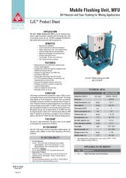
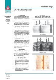
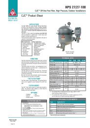
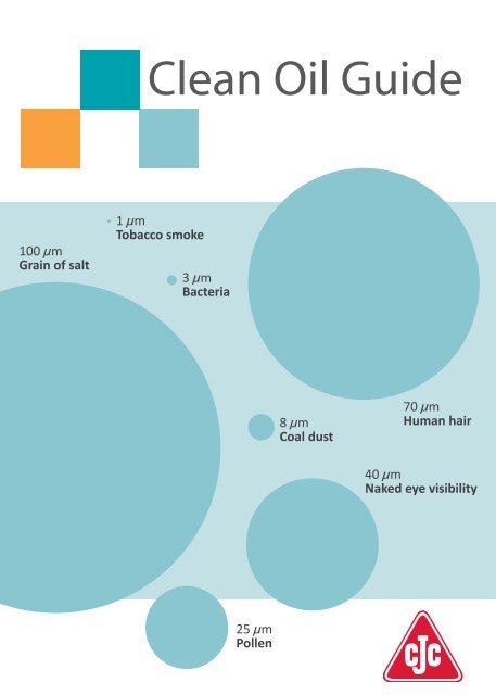
100 µm<br />
Grain of salt<br />
<strong>Clean</strong> <strong>Oil</strong> <strong>Guide</strong><br />
1 µm<br />
Tobacco smoke<br />
3 µm<br />
Bacteria<br />
25 µm<br />
Pollen<br />
8 µm<br />
Coal dust<br />
70 µm<br />
Human hair<br />
40 µm<br />
Naked eye visibility
Contents<br />
2<br />
Page Chapter<br />
3 0 Introduction<br />
4 1 <strong>Oil</strong> contamination control<br />
4 Wear and tear in oil systems<br />
5 Particle contamination<br />
7 Water contamination<br />
8 <strong>Oil</strong> degradation<br />
9 Acid contamination<br />
10 2 <strong>Oil</strong> sampling<br />
10 Where to take an oil sample<br />
11 How to take an oil sample<br />
14 3 <strong>Oil</strong> sample analysis<br />
15 ISO Standards<br />
16 AS / NAS Classes<br />
17 Evaluation of particle count and machine lifetime<br />
18 Analysis methods and frequencies<br />
18 Testing for varnish<br />
20 4 <strong>Oil</strong> cleaning methods<br />
20 Filter types<br />
22 Glass fibre based pressure filter<br />
23 Cellulose based offline filter<br />
24 5 Basic filtration definitions<br />
24 Nominal filtration<br />
24 Absolute filtration<br />
24 Beta values<br />
25 Dirt holding capacity<br />
25 Filter by-pass valve<br />
26 6 Installation methods<br />
26 Full-flow filtration<br />
26 Offline filtration<br />
28 7 Economy<br />
29 8 Ordering a filtration system<br />
29 Offline filter sizing<br />
30 9 CJC <strong>Oil</strong> Maintenance Systems<br />
31 10 Handling of oil and oil systems<br />
31 New oil in containers<br />
31 <strong>Oil</strong> in the system<br />
32 11 Recommendations for buying oil<br />
32 <strong>Oil</strong> test certificates and test sampling<br />
32 Claims<br />
33 Sampling of new oil<br />
34 12 Appendix
Introduction<br />
Introduction<br />
Maintenance is the largest single controllable expense in a<br />
manufacturing plant. With as many as 80% of all machine<br />
failures related to contamination in the oil, pro-active methods<br />
are saving industries considerable costs every year.<br />
This booklet offers an introduction to the problems with<br />
insufficient oil cleanliness, the causes and the remedy of the<br />
problems. All the information presented is generally known<br />
and accepted. It was compiled and published by people within<br />
the company C.C.JENSEN A/S. We invite you to take advantage<br />
of the experience we have gathered over the past 50 years<br />
with oil maintenance within various types of applications. The<br />
perfect oil cleaning system will control the level of all types of<br />
contamination.<br />
For further information, we recommend that you visit<br />
www.cjc.<strong>dk</strong>.<br />
0<br />
3
1 <strong>Oil</strong><br />
4<br />
contamination<br />
control<br />
<strong>Oil</strong> contamination control<br />
The best way to control the oil contamination is to stop the<br />
contaminants from entering the system in the first place.<br />
This entails making sure that all machine components are<br />
clean when installed and that the oil systems are thoroughly<br />
flushed before taken into operation. Furthermore the oil<br />
system should be as well sealed from the environment as<br />
possible with intact seals and gaskets as well as high quality<br />
tank breathers including fine particle and moisture retention<br />
(desiccant and/or bladder type breathers).<br />
The oil should be pre-filtered before coming in contact with<br />
any machine component preferably by continuous filtration in<br />
the lube room / storage area or at least when transferred to<br />
the machines in operation.<br />
Good oil contamination control also includes maintenance<br />
procedures for topping up with oil, replacing parts, taking oil<br />
samples etc.<br />
Wear and tear in oil systems<br />
Any machine using oil for power transmission, lubrication or<br />
combustion will be affected by the condition of the oil. The<br />
oil comes into contact with all components in the system and<br />
should be considered very important – as blood is important in<br />
the human body.<br />
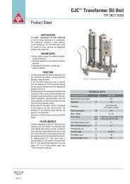
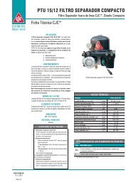
Ø 5 μm<br />
<strong>Oil</strong>groove<br />
Roller<br />
Force<br />
Figure 1: Lubricating a journal bearing<br />
Source: Västeras PetroleumKemi AB<br />
<strong>Oil</strong>groove<br />
Ø 1 μm
Particle contamination<br />
<strong>Oil</strong><br />
contamination<br />
control<br />
Solid particles account for the majority of all failures in an oil<br />
system.<br />
The most harmful are clearance size particles of similar size<br />
or slightly bigger than the dynamic tolerance between the<br />
moving parts in the oil system (figure 1, on page 4).<br />
Dynamic tolerances in an oil system are extremely fine.<br />
Figure 2 indicates the finest tolerance found in different types<br />
of components.<br />
Component<br />
Dynamic oil film<br />
1 µm = 1/1000 mm or same size as tobacco smoke.<br />
<strong>Oil</strong> film<br />
thickness<br />
µm<br />
Journal, slide and sleeve bearings 0.5-100<br />
Hydraulic cylinders 5-50<br />
Engines, ring/cylinder 0.3-7<br />
Servo and proportional valves 1-3<br />
Gear pumps 0.5-5<br />
Piston pumps 0.5-5<br />
Rolling element bearings / ball bearings 0.1-3<br />
Gears 0.1-1<br />
Dynamic seals 0.05-0.5<br />
Figure 2: Dynamic oil film<br />
Source: Noria Corporation<br />
When tiny abrasive particles such as sand and dust get into<br />
the oil system they flow with the oil into critical machine<br />
components and are wedged in the fine clearances. This leads<br />
to micro cracks being initiated in the surface of e.g. a ball<br />
bearing and the load and stress cycles will spread subsurface<br />
cracks resulting in degradation of the metal and releasing large<br />
spalls (figure 3, on page 6).<br />
1<br />
5
1 <strong>Oil</strong><br />
6<br />
contamination<br />
control<br />
1. Particle trapped 2. Cracking initiated<br />
3. Load & stress crack spreads 4. Surface fails + created particles<br />
Figure 3: Fatigue Wear<br />
Excessive amounts of particles stresses the additive package in<br />
the oil. The detergents and dispersants may get depleted if the<br />
particle contamination is not taken under control.<br />
How clean the oil needs to be in terms of particle contamination<br />
depends on how sensitive the machine components are and<br />
how high the penalty for a failure is, i.e. involved costs for<br />
replacement parts, downtime cost, safety liability etc.<br />
Recommendations for targeting the required oil cleanliness, see<br />
page 17.
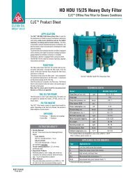
Water contamination<br />
Figure 4:<br />
Micro pitting<br />
<strong>Oil</strong><br />
contamination<br />
control<br />
Water accounts for a major part of mechanical failures. In<br />
some heavily water contaminated oil systems e.g. in the<br />
paper industry, water is the predominant cause of failing<br />
components.<br />
Water reduces the lubricity of the oil, due to the lower<br />
viscosity and poor load capacity of water. When water is<br />
exposed to the high pressures found in load zones in e.g.<br />
bearings and gears, the water droplets collapse (implode). The<br />
resulting micro-jets create micro-pitting in metal surfaces and<br />
can even result in metal-to-metal contact when water vapor<br />
pushes the oil away momentarily.<br />
Free hydrogen ions in the water can further worsen the<br />
situation, since they migrate into machine components making<br />
steel brittle and prone to crack.<br />
Water also results in corrosion and erosion leading to pitting<br />
damage (see figure 21 in appendix, page 34).<br />
Furthermore, water acts as a catalyst for oil degradation,<br />
speeding up the oils tendency to oxidize and form resins,<br />
sludge and varnish.<br />
Water can be found in oil as dissolved, emulsified or free<br />
water. How much water a specific oil can dissolve or keep<br />
suspended in emulsions depends on the base oil, additive<br />
package, temperature and pressure. Some oils are designed<br />
to keep large amounts of water in suspension e.g. engine lube<br />
oils. In order to ensure long oil life and for optimum protection<br />
of machine components it is recommended not to have<br />
emulsified or free water in oil.<br />
For a typical mineral based oil this means less than 100 ppm of<br />
water (0.01%).<br />
Unfortunately many oil analysis reports state water content<br />
very inaccurately as “
1 <strong>Oil</strong><br />
8<br />
contamination<br />
control<br />
<strong>Oil</strong> degradation<br />
Oxidation<br />
Sludge<br />
Varnish<br />
Figure 5:<br />
Varnish on<br />
valve plunger<br />
<strong>Oil</strong> degradation products or soft contaminants are a<br />
widespread problem in most industries. They are precursors of<br />
deposits often referred to as varnish which are known to cause<br />
problems in both hydraulic and lube oil systems.<br />
When oil degrades due to elevated temperatures, water or<br />
chemical contamination e.g. copper, the composition and<br />
functional properties of the oil are changed, resulting in the<br />
following products being formed:<br />
• Acids<br />
• Polymerized compounds which are dissolved<br />
in warm oil (referred to as sludge or resins)<br />
• Varnish precipitating out as deposits on colder<br />
machine components<br />
Varnish products are forming a sticky layer on metal surfaces<br />
and will easily blog fine tolerances, making e.g. directional<br />
control valves seize. Hard particles of all sizes get caught in the<br />
sticky layer, creating a sandpaper like, grinding surface which<br />
radically speeds up machine wear.<br />
Further consequences of varnish can be ineffective oil coolers,<br />
clogged oil passes or inline pressure filters, poor lubrication of<br />
bearings etc.<br />
Whether oil degradation products will cause problems in a<br />
specific oil system depends on how sensitive the machine<br />
components are.<br />
Sludge and varnish can be removed from oil – please see<br />
separate section “<strong>Oil</strong> cleaning methods” at page 20.
Acid contamination<br />
Figure 6:<br />
<strong>Oil</strong> with high AN/TAN<br />
has poor lifetime<br />
<strong>Oil</strong><br />
contamination<br />
control<br />
Acid can be found in oil as by-products of oil degradation,<br />
combustion of gas or fuel, hydrolysis of Ester-based fluids etc.<br />
The amount of acid in oil should be limited, since acid will<br />
cause chemical corrosion of machine components and shorten<br />
the lifetime of the oil, just to mention a few of the unwanted<br />
effects.<br />
Acid number, also referred to as AN or TAN, is measure by<br />
titration with a strong base/alkaline and given in amount of<br />
potassium hydroxide in milligrams required to neutralize the<br />
acid in one gram of oil (mg KOH/g).<br />
Acid numbers should not be allowed to increase more than<br />
+0.5 AN higher than that of new oil, and if +1 AN is spotted<br />
immediate action is required (i.e. if new oil has 0.5 AN, then<br />
1.0 AN is alert and 1.5 AN is alarm value).<br />
Acid can be neutralized or removed from oil in different ways.<br />
The obvious is to use the alkalinity of the oil to neutralize<br />
incoming acid. This is done in gas and diesel engine lube oil<br />
utilizing high base numbers (BN or TBN).<br />
The rule of thumb is to replace the lube oil if the BN falls<br />
below 30% of that of the new lube oil.<br />
Acid formed by hydrolysis in Ester-based fluids<br />
(HFD fluids) used in e.g. turbine control systems,<br />
can cause much harm. Acid numbers twenty times<br />
higher than that of new oil, which have been<br />
seen, result in severe acid corrosion of system<br />
components.<br />
In such fluids the acids number can be lowered and<br />
maintained using a neutralizing catalyst such as Ion<br />
exchange resin, Fullers earth or Aluminum Oxides.<br />
C.C.JENSEN has such ion exchange medium in<br />
combination fine filters in the portfolio.<br />
1<br />
9
2<br />
10<br />
<strong>Oil</strong><br />
sampling<br />
<strong>Oil</strong> sampling<br />
Correct<br />
Wrong<br />
Figure 7:<br />
Pipe cross section<br />
with sampling valves<br />
Source:<br />
Västeras<br />
PetroleumKemi AB<br />
The purpose of oil sampling is to utilize the oil as a messenger<br />
telling how the machine is doing. This can prompt pro-active<br />
actions in order to achieve the highest level of machine<br />
performance and reliability at the lowest possible cost. The<br />
initial samples serve to establish benchmarks and to identify<br />
the machines with critical levels. The routine sampling is<br />
done to document that goals are met and can also provide<br />
indications of abnormal wear that needs to be addressed.<br />
The quality of analysis results depends first on correct<br />
sampling and handling of the sample, secondly on the quality<br />
of the laboratory performing the analysis. The importance of<br />
the knowledge about where and how to take a sample is<br />
paramount and requires special attention.<br />
Where to take an oil sample<br />
Referring to figure 7, preferably derive the oil from a upwards<br />
pointing pipe or bend with turbulent flow to produce a<br />
representative sample. Sampling points fitted on the lower<br />
perimetre of a pipe tend to allow depositing of particles in the<br />
sampling valve.<br />
The best place to sample in order to see how machine<br />
components are doing, is downstream from the machine<br />
before any filtration and before the oil is returned to the<br />
system tank. This will show the undiluted result of any<br />
wear being created in the machine.<br />
The best guarantee of clean oil in the system is to sample<br />
from the most contaminated part of the oil system – the<br />
bottom drain of the system tank.<br />
This bottom drain is typically where the offline/kidney lube<br />
filtration system is connected, so a satisfying oil analysis<br />
result taken from between the pump and the filter housing<br />
of an offline filter, is the best guarantee that the oil and the<br />
system is clean.
If no offline filter system is installed, a vacuum type sampling<br />
pump is a valid option. In such case the sample should be<br />
drawn 10 cm (4 inches) off the lowest part of the tank (see<br />
page 13).<br />
How to take an oil sample<br />
- between the pump and the offline filter<br />
To take an oil sample, the following is required:<br />
• a certified particle free glass or hard plastic bottle<br />
(100-200 mL)<br />
• a cloth<br />
• an open oil container of approx. four litre (one US gallon)<br />
Please read the following instructions carefully before taking<br />
the oil sample.<br />
Steps for oil sampling<br />
Ensure the oil system is under stable operation condition<br />
1. Place the oil container beneath the sampling valve<br />
2. Open and close the valve five times and leave it open<br />
3. Flush the pipe by draining one litre (one US quart) into<br />
the container<br />
4. Open the sample bottle while keeping the cap in your<br />
hand to avoid contaminating it<br />
5. Place the bottle under the oil flow without the pipe<br />
touching the sampling valve<br />
6. Fill the bottle to approximately 80%<br />
7. Place the cap on the bottle immediately after taking<br />
the sample. Close the sampling valve<br />
All samples must be clearly marked with number, place of<br />
sampling, date and oil type/make (see example at page 12)<br />
<strong>Oil</strong><br />
sampling<br />
Steps 1-3<br />
Steps 4<br />
Step 5-6<br />
Step 7<br />
Sampling<br />
point<br />
Sump<br />
Flush<br />
min. 1 L<br />
2<br />
Pump<br />
5 times<br />
Max.<br />
80%<br />
Do not<br />
touch<br />
glass<br />
Figure 8:<br />
<strong>Oil</strong> sampling between<br />
the pump and offline filter<br />
11
2 <strong>Oil</strong><br />
sampling<br />
12<br />
Figure 9: CJC <strong>Oil</strong> Sampling Label<br />
Samples should only be collected with the machine operating<br />
at normal working temperature. When sampling for particle<br />
counting following, the method is very important.<br />
Remember that you can never make a sample any better<br />
(cleaner), than the oil in the system, but it is easy to make<br />
it worse!
How to take an oil sample<br />
- using a vacuum pump<br />
Follow the instructions that came with the pump kit.<br />
The illustrations below show the CJC <strong>Oil</strong> Sampling Kit.<br />
Steps for oil sampling<br />
Vacuum pump<br />
1. Cut a suitable piece of tube off the roll. Use new tube<br />
every time. Push the tube into the pump head. Always<br />
flush tube with 2 L oil before taking the sample<br />
2. Fit the bottle by screwing it unto the pump head<br />
3. Create a vacuum in the bottle by a few pump strokes,<br />
and fill the bottle to approximately 80%<br />
4. Close the lid<br />
Lower the free end of the plastic tube to 10 cm (4 inches)<br />
above the lowest part of the tank, in the center of the tank.<br />
Be careful not to let the tube touch the walls or the bottom<br />
of the reservoir.<br />
Strapping the sample tube to a rod may help to position the<br />
tube. Utilizing a fixed pitot tube installed one third above the<br />
tank bottom can also be recommended.<br />
When you have sealed the bottle, make sure that the label is<br />
filled in with all the information as per example on page 12.<br />
<strong>Oil</strong><br />
sampling<br />
Step 1<br />
Step 2<br />
Step 3<br />
Step 4<br />
Sump<br />
Max.<br />
80%<br />
2<br />
Vacuum<br />
pump<br />
Figure 10:<br />
<strong>Oil</strong> sampling<br />
with a vacuum pump<br />
13
3<br />
<strong>Oil</strong> sample<br />
analysis<br />
<strong>Oil</strong> sample analysis<br />
14<br />
As a minimum, an oil analysis should include:<br />
• a particle count • water content in ppm<br />
• viscosity • acidity level (TAN)<br />
In oil systems prone to varnish problems e.g. gas turbines and<br />
hydraulic control systems, it is recommended to do a varnish<br />
test. Methods are described on page 18.<br />
If the oil additive content is of interest, a spectral analysis<br />
should be included (AES or ICP). The trend is of highest<br />
importance, so it is vital to have a baseline showing the<br />
additive package in the new oil.<br />
It is recommended that the initial tests are performed by an<br />
independent laboratory with expert knowledge on lubricants.<br />
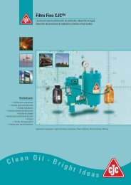
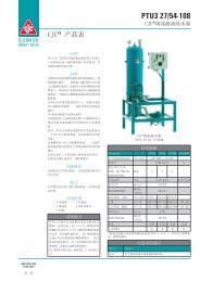
The Millipore membranes show oil degradation if a 0.45 µm<br />
cellulose membrane is utilized.<br />
ISO 11/10/6<br />
ISO 18/17/15<br />
ISO 13/12/7<br />
ISO 20/18/13<br />
ISO 15/13/8 ISO 24/23/20<br />
Figure 11: Test membranes and microscopic photographs<br />
of various contamination levels
ISO Standards<br />
The ISO 4406/1999. Method for coding the level of<br />
contamination by solid particles, was introduced to facilitate<br />
comparisons in particle counting, using automatic particle<br />
counters. Here particles are counted in size 4/6/14 µm.<br />
ISO 4407/1999 is describing particle counting using a<br />
microscope (particle sizes 2/5/15 µm).<br />
For example a typical sample from<br />
new bulk oil, contains in every 100 mL<br />
of oil as follows:<br />
450,000 particles ≥ 4 micron<br />
120,000 particles ≥ 6 micron<br />
14,000 particles ≥ 14 micron<br />
In the ISO classification table<br />
(on the right), this oil sample has a<br />
contamination class of 19/17/14.<br />
Some laboratories give the particle<br />
counting per millilitre in stead of per<br />
100 millilitre (mostly USA).<br />
<strong>Oil</strong> sample<br />
analysis<br />
3<br />
Number of particles per 100 ml fluid after their size ranges<br />
More than Till ISO Class<br />
8,000,000 16,000,000 24<br />
4,000,000 8,000,000 23<br />
2,000,000 4,000,000 22<br />
1,000,000 2,000,000 21<br />
500,000 1,000,000 20<br />
250,000 500,000 19<br />
130,000 250,000 18<br />
64,000 130,000 17<br />
32,000 64,000 16<br />
16,000 32,000 15<br />
8,000 16,000 14<br />
4,000 8,000 13<br />
2,000 4,000 12<br />
1,000 2,000 11<br />
500 1,000 10<br />
250 500 9<br />
130 250 8<br />
64 130 7<br />
32 64 6<br />
Figure 12: Contamination classes according to the<br />
ISO 4406/1999 standard<br />
15
3<br />
16<br />
<strong>Oil</strong> sample<br />
analysis<br />
AS / NAS Classes<br />
The American standard NAS 1638 has been changed to AS4059<br />
(issue E), which is considered to be a significant advance<br />
because it presents data in terms of cumulative counts (>X µm)<br />
rather than interval mode (X-Y µm), introduces a cleaner<br />
(Class 000,) and extends the size range to smaller sizes (>4 µm)<br />
for increased sensitivity.<br />
Correlation tables are available to compare ISO with AS/NAS or<br />
other methods of particle counting.<br />
Size Maximum contamination limits (Particles/100 mL)<br />
ISO 4402 * >1 µm >5 µm >15 µm >25 µm >50 µm<br />
ISO 11171 ** >4 µm(c) >6 µm(c) >14 µm(c) >21 µm(c) >38 µm(c)<br />
SIze Code A B C D E<br />
Class 000 195 76 14 3 1<br />
Class 00 390 152 27 5 1<br />
Class 0 780 304 54 10 2<br />
Class 1 1,560 609 109 20 4<br />
Class 2 3,120 1,220 217 39 7<br />
Class 3 6,520 2,430 432 76 13<br />
Class 4 12,500 4,860 864 152 26<br />
Class 5 25,000 9,730 1,730 306 53<br />
Class 6 50,000 19,500 3,460 612 106<br />
Class 7 100,000 38,900 6,920 1,220 212<br />
Class 8 200,000 77,900 13,900 2,450 424<br />
Class 9 400,000 156,000 27,700 4,900 848<br />
Class 10 800,000 311,000 55,400 9,800 1,700<br />
Class 11 1,600,000 623,000 111,000 19,600 3,390<br />
Class 12 3,200,000 1,250,000 222,000 39,200 6,780<br />
* ISO 4402 or Optical Microscope.<br />
Particle size based on longest dimension<br />
** ISO 11171 or Electron Microscope.<br />
Particle size based on projected area equivalent diameter<br />
Figure 13: AS4059 <strong>Clean</strong>liness Coding System
<strong>Oil</strong> sample<br />
analysis<br />
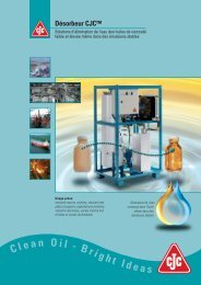
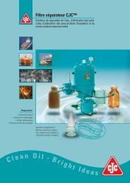
Evaluation of particle count and machine lifetime<br />
In figure 20, on page 34 you can find the Life Extension Table. The table describes<br />
the expected increase in lifetime when the oil cleanliness is improved. Each quadrant<br />
represents a machine type:<br />
• top left quadrant is for hydraulic components and diesel engines<br />
• top right quadrant is for rolling element bearings<br />
• lower left quadrant is for machines incorporating journal bearings e.g. turbines and turbos<br />
• lower right quadrant is for gear boxes and other components not covered by other quadrants<br />
If, for example, the current oil cleanliness in a gear box is found to be ISO 22/20/17<br />
and the oil is cleaned to an ISO cleanliness code of 16/14/11, it can be expected that the<br />
lifetime of the gear is prolonged 2.5 times. For every oil-filled system, a cleanliness goal<br />
should be specified. This is the basic requirement to ensure reliability at the lowest<br />
possible price.<br />
Figure 14 & 15 show the recommended ISO cleanliness levels in hydraulic, lube oil and<br />
gear systems. New oil is typical contaminated with particles to ISO 19/17/14.<br />
ISO Code Description Suitable for Dirt/year<br />
ISO 14/12/10 Very clean oil All oil systems 8.5 kg *<br />
ISO 16/14/11 <strong>Clean</strong> oil Servo & high pressure hydraulics 17 kg *<br />
ISO 17/15/12 Light contaminated oil Standard hydraulic & lube oil systems 34 kg *<br />
ISO 19/17/14 New oil Medium to low pressure systems 140 kg *<br />
ISO 22/20/17 Very contaminated oil Not suitable for oil systems > 589 kg *<br />
Figure 14: Contamination guide for hydraulic and lube oil systems<br />
ISO Code Description Suitable for Improvement factor Dirt/year<br />
ISO 14/12/10 Very clean oil All oil systems 200% 8.5 kg *<br />
ISO 16/14/11 <strong>Clean</strong> oil Critical gear systems 150% 17 kg *<br />
ISO 17/15/12 Light contaminated oil Standard gear systems 100% 34 kg *<br />
ISO 19/17/14 New oil Non critical gear systems 75 % 140 kg *<br />
ISO 22/20/17 Very contaminated oil Not suitable for gear systems 50% > 589 kg *<br />
Figure 15: Contamination guide for gear oil systems<br />
*) The amount of dirt passing the pump per year, if the oil passes with a capacity of 200 ltr/min,<br />
8 hours a day, 230 working days per year<br />
3<br />
17
3 <strong>Oil</strong><br />
18<br />
sample<br />
analysis<br />
Analysis methods and frequencies<br />
Before establishing a trend, it is important to have a baseline<br />
sample of the fresh new oil. This will be used as reference for<br />
later comparison e.g. verifying if the additive package is still<br />
intact.<br />
In the implementation phase of a condition monitoring<br />
system, analyses must be made frequently, at least every three<br />
months, but even better once per month in order to establish<br />
a trend.<br />
A useful trend consists of minimum eight progressive samples<br />
taking from the same oil system under the same operating<br />
conditions.<br />
Every oil system should have a log where analysis results are<br />
registered. The logbook must also contain information about<br />
oil type, oil changes, break-downs, targeted ISO cleanliness<br />
code and oil analysis results.<br />
Testing for varnish<br />
Many types of oil analysis can indicate the oil being degraded<br />
e.g. acid number (TAN), viscosity increase and FTIR, but at<br />
C.C.JENSEN we have found that the two following tests give a<br />
very detailed picture of the varnish problem:<br />
1. Millipore patch test or colorimetric patch test (MPC) shows<br />
sludge/resin/varnish present in the oil by dis-colorization<br />
of the white cellulose patch. This indicates oil degradation<br />
products, also dissolved in the oil, which may or may not result<br />
in varnish on machine components (depending on the oil<br />
temperature). The darker the color and the higher the number<br />
(typically up to 100) the more the oil is prone to form varnish<br />
deposits.
2. Ultra Centrifuge test (UC) uses centrifugal force to extract<br />
the sludge and varnish precursors, driving them to the bottom<br />
of the test tube. The density/size of the concentrated material<br />
is then compared to a visual sediment-rating scale giving a<br />
number of 1 – 8 (8 being the worst).<br />
The UC test shows the actual varnish and insoluble<br />
contaminants in the oil. Any oil degradation seen in this test<br />
will result in varnish as deposits on system components.<br />
The UC test is not recommended for oil highly contaminated<br />
with particles, because it masks the result, nor for Ester or<br />
Glycol based fluids, since specific gravity plays a role in the UC<br />
test.<br />
UC and MPC tests are very useful tools to trigger an action e.g.<br />
install a filter or change the oil.<br />
Figure 16: UC Analysis and MPC Test Result<br />
<strong>Oil</strong> sample<br />
analysis<br />
3<br />
19
4<br />
20<br />
<strong>Oil</strong><br />
cleaning<br />
methods<br />
<strong>Oil</strong> cleaning methods<br />
Several oil cleaning methods are available:<br />
Method <strong>Clean</strong>ing action<br />
Cellulose based offline filter<br />
Reduces the content of solid particles, water and oil degradation<br />
products<br />
Glass fibre based pressure filter Reduces the content of solid particles<br />
Electrostatic filter Reduces the content of solid particles, and oil degradation products<br />
Centrifugal separator<br />
Reduces the content of solid particles with a density higher than<br />
that of oil as well as water<br />
Vacuum filter Reduces the content of air and water<br />
Figure 17: <strong>Oil</strong> cleaning methods<br />
All the above technologies are commercially available. However the glass fibre<br />
based pressure filter and the cellulose based offline filter, are often preferred due<br />
to their superior efficiency and economy. Both of these oil filter techniques work<br />
best under constant conditions, i.e. steady flow and pressure.<br />
The cellulose based depth filter is often placed in a separate offline circuit also called<br />
kidney loop filtration, and with such stable conditions, it retains the majority<br />
of contaminants found in the oil. The glass fibre based pressure filter could be<br />
installed in an oil cooling circuit or as a full-flow “last chance” filter upstream of<br />
the oil system.<br />
Filter types<br />
The best method for capturing and retaining fine particles as well as water and<br />
varnish is by installing an offline filter. An offline filter should operate continuously,<br />
circulating the oil volume in the system many times per day. With a low pressure<br />
and low flow rates a dense filter medium with very fine filtration can be selected<br />
(< 3 micron filtration).<br />
The cellulose based offline filter is like a maze where the oil passes through<br />
several layers of cellulose. The largest particles are retained on the surface of the<br />
filter insert whereas the smaller particles enter the filter insert and are retained<br />
within the filter material, this ensures a high dirt holding capacity. This type of
filter can also be installed in a by-pass circuit, throttling the pressure of the system<br />
pump. Using a cellulose based offline filter also enables removal of water, by<br />
absorption or coalescing, and removal of oil degradation products such as sludge/<br />
varnish from the oil.<br />
Varnish can be removed from oil systems through the detergent/dispersant<br />
additives in the oil, but the oil needs to be clean from particles, water and sludge<br />
before the additives are free to do the varnish cleaning job. Since sludge and<br />
varnish precipitate out of cold oil, typically between 10 - 40 ◦ C (50 - 100 ◦ F), cooling<br />
the oil in the offline filtration circuit combined with a cellulose based depth filter is<br />
highly effective.<br />
The CJC Offline Filters removes oil degradation products such as sludge and<br />
varnish through polar attraction to the filter medium. A combination of adsorption<br />
and absorption fills each cellulose fibre with oil degradation products until the<br />
insert completely is saturated. The CJC Filter Inserts can hold up to 4 kgs (8 lbs)<br />
of varnish depending on type.<br />
Conventional inline pressure filters are typically glass fibre based, because they<br />
need to operate under high pressure and high flow conditions, while creating as<br />
little restriction as possible. The filter element is pleated in order to increase the<br />
surface area and reduce the pressure drop.<br />
Since they are installed after the main system pump, they often live a tough<br />
life with cyclic flows and many stops and starts, which is very harmful for the<br />
efficiency of any filter. Capturing and retaining fine silt particles is therefore very<br />
difficult, which is why most of these inline filters have a rating of 10 – 30 micron.<br />
However, many already captured particles will be released again when the filter is<br />
exposed to pressure shocks at stop/start.<br />
The glass fibre based pressure filter is capable of removing solid particles only<br />
– and due to the relatively small filter depth and volume, it has a restricted dirt<br />
holding capacity.<br />
See illustrations on pages 22-23.<br />
<strong>Oil</strong><br />
cleaning<br />
methods<br />
Modern oil systems often combine the two cleaning systems, where the offline<br />
filter removes the contamination and the inline pressure filter serves as security or<br />
“last chance” filter before critical components.<br />
4<br />
21
4 <strong>Oil</strong><br />
cleaning<br />
methods<br />
22<br />
Glass fibre based pressure filter<br />
Element housing<br />
O-Ring<br />
End cap<br />
seal<br />
Core<br />
Medium<br />
support<br />
Pleat<br />
support<br />
band<br />
End cap<br />
Filter<br />
element<br />
Function<br />
Pressure filters have a limited dirt holding capacity,<br />
usually between 1 and 100 grams, which results<br />
in filter element replacement at short intervals in<br />
order to ensure efficient filtration.<br />
Typical filtration rating on inline pressure filters are<br />
5 – 50 micron.<br />
Outer filter casing<br />
Unfiltered oil entry<br />
under high pressure<br />
<strong>Oil</strong><br />
flow<br />
Trapped particles<br />
Conventional glass fibre based inline pressure filters<br />
do not absorb water, nor retain oil degradation<br />
products such as sludge and varnish.<br />
Filtered oil<br />
returned<br />
to oil circuit<br />
Filter medium<br />
Support layer<br />
Support<br />
layer<br />
Filter<br />
medium<br />
layer
Cellulose based offline filter<br />
The CJC Offline Filter has a large dirt holding capacity<br />
of approximately 4 L solids, up to 2 L of water<br />
and 4 L oil degradation products (varnish). The CJC<br />
Offline Filters typically only need replacing every 12<br />
months.<br />
The CJC Offline Filter will filter effectively down to<br />
3 µm absolute and remove water and oil degradation<br />
products (oxidation products, resin, sludge and<br />
varnish) from the oil, continuously cleaning machine<br />
components and the whole oil system.<br />
<strong>Oil</strong><br />
cleaning<br />
methods<br />
Filter Insert<br />
Made of corrugated wood cellulose discs rotated at 90°<br />
to the next and bonded together. This gives a series<br />
of connected surfaces with corrugations running northsouth<br />
and east-west.<br />
Filter housing<br />
Function<br />
Filtered oil returned<br />
to the oil circuit<br />
Unfiltered oil enters<br />
under pressure<br />
Particles pass<br />
through the<br />
filter maze until<br />
they are trapped<br />
4<br />
23
5<br />
24<br />
Basic<br />
filtration<br />
definitions<br />
Basic filtration definitions<br />
Contaminant<br />
Test filter<br />
Figure 18: Multipass test<br />
Source: ISO Standards<br />
Nominal filtration ratings are estimated values, indicating a<br />
particulate size range at which the filter is claimed to remove a given<br />
percentage. There is no standard for this, so consequently, different<br />
products/makes cannot be compared. Operating pressure and<br />
concentration of contaminants will affect the retention efficiency of<br />
filters with nominal rating.<br />
Absolute filtration ratings describe the pore size, indicating the<br />
largest size of particle which can pass through the filter. The filter<br />
needs to apply to a standard test method intended for filter usage.<br />
The rating of a cellulose based offline filter is often 3 µm absolute or<br />
less. The rating of a glass fibre based pressure filter varies according<br />
to the requirements of the system component(s) to be protected.<br />
Beta values describe filter efficiencies at given particle sizes. The<br />
value is written ßx, where the ”x” represents the particle size in<br />
question and ß (”beta”) is the efficiency e.g. ß3 = 200, which means<br />
that one out of 200 particles of 3 micron in size will pass through the<br />
filter (0.5% passes through and 99.5% are retained in one pass).<br />
In order to find the Beta value a standardized “Multipass test ISO<br />
16889” is used, and the Beta value is calculated by the following<br />
formula.<br />
ND<br />
NU<br />
ßx =<br />
ßX = NU<br />
ND<br />
number of particles upstream > x (N U )<br />
number of particles downstream > x (N D )<br />
Filter efficiency<br />
ßX - 1<br />
E = x 100<br />
ßX<br />
This Multipass test is<br />
performed under controlled<br />
laboratory conditions and does<br />
not take into account some of<br />
the challenges an inline pressure<br />
filter will see in most oil<br />
systems, such as air bubbles,<br />
vibrations, pressure pulses<br />
from stop-start etc.
Dirt holding capacity is the quantity of contamination<br />
retained by the filter insert when the saturation pressure is<br />
reached. This is measured in weight or volume. How much oil<br />
contamination a filter insert is capable of retaining is of highest<br />
importance for the cost of operating over a period of time.<br />
While most conventional pleated pressure filter inserts can<br />
retain less than hundred grams of dirt (
6<br />
26<br />
Installation<br />
methods<br />
Installation methods<br />
Full-flow filtration<br />
The total system flow passes through the filter.<br />
Only pressure filter elements are applicable here.<br />
Offline filtration<br />
An installation method where the filtration unit operates<br />
in a separate kidney loop circuit, enabling the use of dense<br />
filter inserts.<br />
<strong>Oil</strong> system diagram
Contaminants can pass the<br />
filter when by-pass valves<br />
cannot close completely<br />
after they have opened.<br />
Millipore<br />
membrane. Sample<br />
taken after offline<br />
filtration.<br />
FLOW<br />
In-line<br />
filter<br />
System<br />
pump<br />
H 2 O<br />
SUMP<br />
Offline filter<br />
FLOW<br />
Installation<br />
methods<br />
If the inline<br />
filter is not changed<br />
regularly it will clog<br />
and allow particles<br />
to pass through the<br />
by-pass valve.<br />
6<br />
Contaminated<br />
Millipore<br />
membrane.<br />
Sample taken<br />
before offline<br />
filtration.<br />
27
7<br />
28<br />
Economy<br />
Economy<br />
Before investing in a filtration system, a cost benefit study<br />
should be carried out. The involved costs can be divided into<br />
two groups:<br />
• Purchase costs: costs directly related to the purchase of<br />
a filtration system, i.e. purchase price and installation costs.<br />
• Operational costs: costs for keeping the filtration system<br />
unit in operation, i.e. replacement of filter inserts, energy<br />
consumption and repairs.<br />
Purchase Costs + Operational Costs = Total Investment<br />
The total investment has to be lower than the savings obtained<br />
through clean oil.<br />
• Savings: the reductions in maintenance costs, the<br />
minimizing of lost production hours, prolonged service<br />
intervals, longer oil lifetime, extended component life, etc.<br />
In most applications the payback period or the Return Of<br />
Investment for a CJC Offline Filter is typically from a few<br />
weeks up to some month, but rarely more than one year.<br />
In industries where any downtime is very costly e.g. steel<br />
production, the payback period can be a few hours. This means<br />
that if the improved oil condition leads to e.g. just 3 hours of<br />
additional production, the filtration system has paid for itself.<br />
Because the operation cost of the filter solution also plays a<br />
role in the total investment, it is relevant to look at how much<br />
oil contamination the filter is capable of retaining – the socalled<br />
dirt holding capacity.<br />
Most conventional pressure filters can retain less than hundred<br />
grams of dirt (less than 0.2 lbs), so they will need to be<br />
replaced more often than a good quality cellulose based offline<br />
filter capable of retaining several kg or lbs of dirt.<br />
The cost of removing 1 kg (or pound) of dirt from the oil is a<br />
good factor for comparing different filter makes and help to<br />
find the lowest cost of ownership (the total investment).<br />
See the calculation of the cost for removing 1 lb dirt on page 25.
Ordering a filtration system<br />
Ordering<br />
a filtration<br />
system<br />
In the quote for a filtration system from any supplier the<br />
following should be included:<br />
• Operational costs of the filter over a period of min.<br />
5 years (power, filter inserts, spares etc.)<br />
• Obtainable fluid system cleanliness level<br />
(e.g. ISO 17/15/12 and 200 ppm water)<br />
• Control procedure confirming that the cleanliness<br />
level has been achieved (e.g. oil samples)<br />
Offline filter sizing<br />
When sizing an offline filter the following basic information<br />
about the oil system should be specified:<br />
• <strong>Oil</strong> volume in the system (tank volume)<br />
• <strong>Oil</strong> type (ISO VG)<br />
• <strong>Oil</strong> temperature: Normal operation and minimum<br />
temperatures (ambient)<br />
• <strong>Oil</strong> contamination problem:<br />
○ particles<br />
○ oil degradation products, sludge and varnish<br />
○ water (ingress or accumulated)<br />
• Type of application (indoor/clean, outdoor/dirty,<br />
severe ingress etc.)<br />
• Machine operating hours per day<br />
• Available power supply<br />
This information will help your local distributor to size the<br />
correct CJC Filter for your oil system.<br />
Aside from continuous filtration of the oil in machines, drums<br />
or bulk tanks, the CJC Offline Filters can also be utilized for<br />
filling and topping up with oil, thus ensuring that only clean oil<br />
enters the system.<br />
8<br />
29
9 CJC<br />
30<br />
<strong>Oil</strong><br />
Maintenance<br />
Systems<br />
CJC <strong>Oil</strong> Maintenance Systems<br />
CJC HDU Fine Filter<br />
• Dry oil with limited water content<br />
(accumulated over time)<br />
• Hydraulic, lube and gear oils – also<br />
Glycols or Ester based fluids<br />
• Retains particles and varnish<br />
• Water removal by absorption (free,<br />
emulsified and some dissolved water)<br />
• Reduce acidity level utilizing ion exchange inserts<br />
CJC PTU Filter Separator<br />
• Water contaminated oil and diesel<br />
• Hydraulic, lube and gear oils – up to ISO VG 150<br />
• Retains particles and varnish<br />
• Free water is removed by separation (coalescing)<br />
• Suitable for oil with good demulsibility (not engine<br />
oil, Ester based fluids etc.)<br />
CJC Desorbers<br />
• Water contaminated oil – even with strong<br />
emulsions<br />
• Hydraulic, lube and gear oils – up to ISO VG 1000<br />
(depending on Desorber type)<br />
• Removes both free, emulsified and dissolved water<br />
• Suitable for most oils even engine oil, paper<br />
machine oil etc.<br />
CJC Desorbers do not retain particles and varnish, thus<br />
a separate CJC HDU Fine Filter is recommended.<br />
CJC Varnish Removal Unit<br />
• Dry oil with limited water content<br />
• Retains varnish very effectively<br />
• Suitable for systems with servere varnish production<br />
e.g. gas turbines
Handling of oil<br />
and oil systems<br />
Handling of oil and oil systems<br />
New oil in containers<br />
• New oil should be considered contaminated until a<br />
sample has been analyzed<br />
• <strong>Oil</strong>s containing additives that are not necessary for<br />
the application are to be considered contaminated<br />
• New oil should always be introduced to the system<br />
via a filter, preferably a 3 µm absolute filter<br />
• Do not mix oils without previously investigating<br />
compatibility<br />
• Keep lubricating products in closed containers to<br />
avoid ingress of contaminants<br />
10<br />
<strong>Oil</strong> in the system<br />
• Observe the oil regularly during operation in order to<br />
discover any sudden appearance of water, air or other<br />
contaminants. Using fresh oil as a reference may be<br />
he lpful<br />
• Check the oil after machine malfunctions or other<br />
incidents which might affect the oil<br />
• Always observe maximum cleanliness and accuracy<br />
during sampling<br />
• Systems should be sealed as much as possible. All<br />
permanent openings should be equipped with venting<br />
filters (preferably desiccant breathers). All systems<br />
should be equipped with permanent filter installations<br />
• When changing the oil, the tank and the system should<br />
be emptied completely and the tank should be cleaned<br />
manually of settlings, sludge etc. (this can be avoided by<br />
installing CJC Offline Filters)<br />
• When replacing seals, only oil-resistant materials should<br />
be used. Compatibility with the oil should be checked.<br />
• Never apply new additives without consulting the oil<br />
supplier/consultant. Ask for written confirmation of the<br />
measures to be taken<br />
• Always use independent analysis resources with high<br />
quality control and repeatability<br />
31
11<br />
32<br />
Recommendations<br />
for buying oil<br />
Recommendations for buying oil<br />
When buying oil in bulk, buyers have a right to set specific<br />
certified requirements to ensure the quality.<br />
Below find some examples of requirements and test for the<br />
quality of the oil, emphasizing oil cleanliness.<br />
<strong>Oil</strong> test certificates and test sampling<br />
The results of an oil test of the batch should be presented to<br />
the buyer. A sample should be taken during the filling of the<br />
first batch. Samples should be marked with the trademark,<br />
batch number and size of the consignment. The oil should<br />
be analyzed by an independent laboratory and the analysis<br />
should include the data described in the oil analysis section of<br />
this booklet.<br />
Claims<br />
If the oil supplied does not fulfill requirements, returning<br />
the consignment might be considered. If the problem can be<br />
corrected, new samples must be approved. The supplier must<br />
pay all costs, including machinery failure and downtime.
Recommendations<br />
for buying oil<br />
Sampling of new oil<br />
Samples must be drawn from each manufactured batch. The<br />
analysed sample must be a representative sample of the<br />
manufactured batch. Test records must be available for the<br />
buyer for at least five years.<br />
An analysis certificate must be delivered together with the<br />
ordered oil and include at least the following items:<br />
• Visual inspection<br />
• Viscosity @ 40 ◦ C<br />
• Density<br />
• Total Acid Number of finished product<br />
• Air bubble separation time<br />
• Contaminants, gravimetric or ISO cleanliness code<br />
For wind turbine oils, foaming at 50 ◦ C could be included.<br />
The oil must be delivered by tanker trucks, epoxy-painted<br />
drums or 20-litre cans. The buyer must indicate the type of<br />
container for each individual case. The container must be<br />
of first class quality and the type generally used in the oil<br />
trade. The container must be marked with the buyer’s trade<br />
description, the suppliers trade designation, net content and a<br />
continuous manufacturing batch number.<br />
11<br />
33
12 Appendix<br />
34<br />
CLEAN OIL Appendix<br />
BRIGHT IDEAS<br />
www.cjc.<strong>dk</strong><br />
Current<br />
Machine<br />
<strong>Clean</strong>liness<br />
(ISO CCode) d )<br />
24/22/19<br />
23/21/18<br />
22/20/17<br />
21/19/16<br />
20/18/15<br />
19/17/14<br />
18/16/13<br />
LET – <strong>Clean</strong>liness Level<br />
ISO Codes Codes, Complete<br />
Expected <strong>Clean</strong>liness level (ISO Code)<br />
Life Extension Table<br />
Source: Noria Corp.<br />
21/19/16 20/18/15 19/17/14 18/16/13 17/15/12 16/14/11 15/13/10 14/12/9 13/11/8 12/10/7<br />
2 1.6<br />
1.8 1.3<br />
1.5 1.5<br />
1.5 1.3<br />
1.3 1.2<br />
1.2 1.05<br />
3 2<br />
2.3 1.7<br />
2 1.7<br />
1.8 1.4<br />
1.6 1.5<br />
1.5 1.3<br />
1.3 1.2<br />
1.2 1.1<br />
4 2.5<br />
3 2<br />
3 2<br />
2.2 1.6<br />
2 1.7<br />
1.8 1.4<br />
1.6 1.5<br />
1.5 1.3<br />
1.3 1.2<br />
1.2 1.1<br />
6 3<br />
3.5 2.5<br />
4 2.5<br />
3 2<br />
3 2<br />
2.3 1.7<br />
2 1.7<br />
1.8 1.5<br />
1.6 1.5<br />
1.5 1.3<br />
1.3 1.2<br />
1.2 1.1<br />
7 3.5<br />
4.5 3<br />
5 3<br />
3.5 2.5<br />
4 2.5<br />
3 2<br />
3 2<br />
2.2 1.7<br />
2 1.7<br />
1.8 1.5<br />
1.6 1.5<br />
1.5 1.3<br />
1.3 1.2<br />
1.2 1.1<br />
8 4<br />
5.5 3.5<br />
7 3.5<br />
4.5 3<br />
5 3<br />
3.5 2.5<br />
4 2.5<br />
3 2<br />
3 2<br />
2.3 1.7<br />
2 1.7<br />
1.8 1.5<br />
1.6 1.5<br />
1.5 1.3<br />
1.3 1.2<br />
1.2 1.1<br />
>10 5<br />
7 4<br />
9 4<br />
5 3.5<br />
7 4<br />
5 3<br />
5 3<br />
3.5 2.5<br />
4 2.5<br />
3 2<br />
3 2<br />
2.3 1.7<br />
2 1.7<br />
1.8 1.5<br />
1.6 1.5<br />
1.5 1.4<br />
1.3 1.3<br />
13 12<br />
>10 6<br />
8 5<br />
>10 5<br />
7 4<br />
9 5<br />
6 4<br />
7 4<br />
5 3.5<br />
5 3<br />
3.5 2.5<br />
4 2.5<br />
3 2<br />
3 2<br />
2.3 1.8<br />
2 1.7<br />
1.8 1.5<br />
1.6 1.6<br />
16 14<br />
1.4 1.2<br />
1.2 1.1<br />
>10 7<br />
10 5.5<br />
>10 7<br />
9 5.5<br />
>10 7<br />
8 5.5<br />
9 6<br />
7 4.5<br />
7 4.6<br />
5.5 3.7<br />
6 3<br />
4 2.5<br />
4 3.5<br />
3.7 3<br />
3 2<br />
2.3 1.8<br />
2 1.8<br />
19 15<br />
1.8 1.5<br />
1.6 1.3<br />
>10 >10<br />
>10 8.5<br />
>10 10<br />
10 8<br />
>10 9<br />
10 7<br />
>10 8<br />
9 6<br />
>10 6<br />
8 5<br />
8 5<br />
6 3.5<br />
6 4<br />
4.5 3.5<br />
4 2.5<br />
3 2.2<br />
3 2<br />
23 18<br />
2.5 1.8<br />
2 1.6<br />
1.5 1.3 1.8 1.4 2.2 1.6 3 2 3.5 2.5 4.5 3 5 3.5 7 4 9 5.5 10 8<br />
Hydraulics Rolling<br />
13 12 16 15 2 17 3 2 4 35 6 4<br />
and Diesel Element<br />
17/15/12<br />
Engines Bearings<br />
16/14/11<br />
15/13/10<br />
Journal<br />
Bearings<br />
and Turbo<br />
Machinery<br />
Gear<br />
Boxes<br />
and others<br />
1.3 1.2 1.6 1.4 1.9 1.5 2.3 1.8<br />
CLEAN OIL<br />
Figure 20: Life Extension Table, cleanliness level<br />
C.C.JENSEN A/S - LET, <strong>Clean</strong>liness Level, ISO Codes, Complete – No. 17-01, April 2007 Page 1<br />
BRIGHT IDEAS<br />
www.cjc.<strong>dk</strong><br />
Current Moisture<br />
Level, ppm<br />
LEM - MOISTURE Level<br />
Life Extension Factor<br />
Life Extension Method<br />
Source: Noria Corp.<br />
2 3 4 5 6 7 8 9 10<br />
50,000 12,500 6,500 4,500 3,125 2,500 2,000 1,500 1,000 782<br />
25,000 6,250 3,250 2,250 1,563 1,250 1,000 750 500 391<br />
10 10,000 000 22,500 500 11,300 300 900 625 500 400 300 200 156<br />
5,000 1,250 650 450 313 250 200 150 100 78<br />
2,500 625 325 225 156 125 100 75 50 39<br />
1,000 250 130 90 63 50 40 30 20 16<br />
500 125 65 45 31 25 20 15 10 8<br />
260 63 33 23 16 13 10 8 5 4<br />
100 25 13 9 6 5 4 3 2 2<br />
1% water = 10,000 ppm. ● Estimated life extension for mechanical systems utilizing mineral-based fluids.<br />
Example: By reducing average fluid moisture levels from 2500 ppm<br />
to 156 ppm, machine life (MTBF) is extended by a factor of 5.<br />
C.C.JENSEN A/S - LEM, MOISTURE Level, No. 17-03, April 2007 Page 1<br />
Figure 21: Life Extension Method, moisture level
<strong>Clean</strong> <strong>Oil</strong> <strong>Guide</strong><br />
Sixth Edition 2011<br />
English version<br />
Published by:<br />
C.C.JENSEN A/S<br />
Svendborg, Denmark<br />
Revision & layout:<br />
C.C.JENSEN A/S, Marketing Department<br />
Svendborg, Denmark<br />
Print:<br />
Tryk Team<br />
Svendborg, Denmark<br />
Sources:<br />
”Chemistry in electrical apparatuses”<br />
Lars Arvidsson<br />
Västeras PetroleumKemi AB<br />
C.C.JENSEN A/S
C.C.JENSEN Subsidiaries and Sales Offices<br />
Belgium<br />
C.C.JENSEN Belgium<br />
Tel.: +32 484 25 36 96<br />
ccjensen.be@cjc.<strong>dk</strong><br />
www.ccjensen.be<br />
Benelux<br />
C.C.JENSEN Benelux B.V.<br />
Tel.: +31 182 37 90 29<br />
ccjensen.nl@cjc.<strong>dk</strong><br />
www.ccjensen.nl<br />
Chile<br />
C.C.JENSEN S.L. Limitada<br />
Tel.: +56 2 739 2910<br />
ccjensen.cl@cjc.<strong>dk</strong><br />
www.ccjensen.cl<br />
China<br />
C.C.JENSEN A/S China<br />
Tel: +86 10 6436 4838<br />
ccjensen.cn@cjc.<strong>dk</strong><br />
www.ccjensen.cn<br />
Your Local CJC Distributor<br />
Denmark<br />
C.C.JENSEN Danmark<br />
Tel: +45 7228 2222<br />
ccjensen.<strong>dk</strong>@cjc.<strong>dk</strong><br />
www.cjc.<strong>dk</strong><br />
France<br />
C.C.JENSEN France<br />
Tel: +33 3 59 56 16 58<br />
ccjensen.fr@cjc.<strong>dk</strong><br />
www.ccjensen.fr<br />
Germany<br />
KARBERG & HENNEMANN<br />
GmbH & Co. KG<br />
Tel: +49 (0)40 855 04 79 0<br />
kontakt@cjc.de<br />
www.cjc.de<br />
Greece<br />
C.C.JENSEN Greece LTD.<br />
Tel.: +30 210 42 81 260<br />
ccjensen.gr@cjc.<strong>dk</strong><br />
www.ccjensen.gr<br />
Head office:<br />
C.C.JENSEN A/S<br />
Løvholmen 13 | DK - 5700 Svendborg | Denmark<br />
Tel. +45 6321 2014 | Fax: +45 6222 4615<br />
filter@cjc.<strong>dk</strong> | www.cjc.<strong>dk</strong><br />
Ireland<br />
C.C.JENSEN Ireland<br />
Tel.: +353 61 374 943<br />
ccjensen.ie@cjc.<strong>dk</strong><br />
www.ccjensen.ie<br />
Italy<br />
KARBERG & HENNEMANN srl<br />
Tel: +39 059 29 29 498<br />
info@cjc.it<br />
www.cjc.it<br />
Poland<br />
C.C.JENSEN Polska Sp. z o.o.<br />
Tel.: +48 22 648 83 43<br />
ccjensen@ccjensen.com.pl<br />
www.ccjensen.pl<br />
Spain<br />
C.C.JENSEN Ibérica, S. L.<br />
Tel.: +34 93 590 63 31<br />
ccjensen.es@cjc.<strong>dk</strong><br />
www.cjc.<strong>dk</strong><br />
We are represented<br />
globally by distributors.<br />
Find your nearest distributor<br />
on our website: www.cjc.<strong>dk</strong><br />
- or give us a call.<br />
United Arab Emirates<br />
C.C.JENSEN Middle East<br />
Tel: +971 4 447 2886<br />
ccjensen.uae@cjc.<strong>dk</strong><br />
www.cjc.ae<br />
United Kingdom<br />
C.C.JENSEN LTD.<br />
Tel.: +44 1 388 420 721<br />
filtration@cjcuk.co.uk<br />
www.ccjensen.co.uk<br />
USA<br />
C.C.JENSEN INC.<br />
Tel.: +1 770 692 6001<br />
ccjensen@ccjensen.com<br />
www.ccjensen.com