Installation and Operation Manual Laars Lite 2™ Pool ... - Igor Chudov
Installation and Operation Manual Laars Lite 2™ Pool ... - Igor Chudov
Installation and Operation Manual Laars Lite 2™ Pool ... - Igor Chudov
Create successful ePaper yourself
Turn your PDF publications into a flip-book with our unique Google optimized e-Paper software.
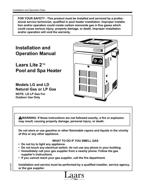
<strong>Installation</strong> <strong>and</strong> <strong>Operation</strong> DataFOR YOUR SAFETY - This product must be installed <strong>and</strong> serviced by a professionalservice technician, qualified in pool heater installation. Improper installation<strong>and</strong>/or operation could create carbon monoxide gas in flue gases whichcould cause serious injury, property damage, or death. Improper installation<strong>and</strong>/or operation will void the warranty.<strong>Installation</strong> <strong>and</strong><strong>Operation</strong> <strong>Manual</strong><strong>Laars</strong> <strong>Lite</strong> 2<strong>Pool</strong> <strong>and</strong> Spa HeaterModels LG <strong>and</strong> LDNatural Gas or LP GasNOTE: LD LP Gas ForOutdoor Use OnlyWARNING: If these instructions are not followed exactly, a fire or explosionmay result, causing property damage, personal injury, or death.Do not store or use gasoline or other flammable vapors <strong>and</strong> liquids in the vicinityof this or any other appliance.WHAT TO DO IF YOU SMELL GAS• Do not try to light any appliance.• Do not touch any electrical switch; do not use any phone in your building.• Immediately call your gas supplier from a nearby phone. Follow the gassupplier’s instructions.• If you cannot reach your gas supplier, call the fire department.H0235900-<strong>Installation</strong> <strong>and</strong> service must be performed by a qualified installer, service agency,or the gas supplier.
TABLE OF CONTENTSSECTION 1.General Information1A. Introduction................................................... 11B. Description ................................................... 21C. Warranty....................................................... 21D. Technical Assistance .................................... 2SECTION 2.<strong>Installation</strong> Instructions2A. General Information ..................................... 22B. Field Assembly ............................................. 22C. Site Location ................................................ 32C-1. <strong>Installation</strong> Information ................................. 32C-2. Outdoor <strong>Installation</strong> ...................................... 42C-3. Flooring - Typical <strong>Installation</strong> ....................... 42C-4. Indoor <strong>and</strong> Outdoor Shelter <strong>Installation</strong> ........ 42D. Combustion <strong>and</strong> Ventilation Air Supply ........ 52E. Gas Supply <strong>and</strong> Piping ................................. 52E-1. General Instructions ..................................... 52E-2. Special Precautions for Propane Gas .......... 62F. Electrical Wiring ........................................... 62F-1. General Information (LD Only) ..................... 62F-2. Auxiliary Time Clock Wiring ......................... 82F-3. Remote <strong>Operation</strong> (Model LD Only) ............. 92G. Water Flow System ...................................... 92G-1. Flange <strong>Installation</strong> ........................................ 92G-2. Reversible Water Connections ................... 102G-3. Valve <strong>Installation</strong> ........................................ 122G-4. Chlorinators, Ozone Generators, <strong>and</strong>Sanitizing Chemicals .................................. 122G4a Water Chemistry ........................................ 132G-5. Pressure Relief Valve ................................. 132G-6. Adjusting the Pressure Switch .................... 132G-7. Automatic Flow Control Valve .................... 142G-8. Temperature Rise ....................................... 142G-9. Adjusting the <strong>Manual</strong> Bypass Valve ........... 15SECTION 3.Operating Instructions3A. General Information ................................... 163B. Lighting <strong>and</strong> Shutdown Procedures ............ 163B-1. Model LD (Direct Ignition) .......................... 163B-2. Model LG (St<strong>and</strong>ing Pilot) .......................... 163C. Setting the Temperature Control ................ 163D. Seasonal Care ............................................ 193D-1. Spring <strong>and</strong> Fall <strong>Operation</strong> .......................... 193D-2. Winterizing ................................................. 193D-3. Spring Startup ............................................ 193E. Water Chemistry ........................................ 203F. Spa/Hot Tub Safety Rules .......................... 203G. Swimming <strong>Pool</strong> Energy Saving Tips .......... 203H. Periodic Inspection ..................................... 213H-1. Owner Inspection........................................ 213H-2. Professional Inspection .............................. 21SECTION 4.Parts List for <strong>Laars</strong> <strong>Lite</strong> 2 Heater4A. General Information .................................. 214B. Parts List ................................................... 21
Model LG & LD <strong>Pool</strong> <strong>and</strong> Spa Heater Page 1SECTION 1.General Information1A. IntroductionThis manual provides installation <strong>and</strong> operationinstructions for the <strong>Laars</strong> <strong>Lite</strong> 2, Model LG <strong>and</strong> LDpool <strong>and</strong> spa heaters. Read these installation <strong>and</strong>operation instructions completely before proceedingwith the installation. Consult the Waterpik <strong>Laars</strong>factory, or local factory representative, with anyquestions regarding this equipment. Experience hasshown that most operating problems are caused byimproper installation.The <strong>Laars</strong> <strong>Lite</strong> 2 heater is design certified byInternational Approval Services (formerly AmericanGas Association <strong>and</strong> Canadian Gas Association) ascomplying with the latest edition of the St<strong>and</strong>ard for(920 cm)Venting DimensionsModel Heater U.S. Indoor or Firing Rate / Hr.Size Width Vent U.S. Outdoor CAN Outdoor (1,000's)Diameter Dim "H" Shelter Dim "H"Notes:1. In Canada, derate BTU/Hr input <strong>and</strong> output 10 percent for altitudes of 2,000 to 4,500 feet (609 to 1372 m) above sealevel. No derating necessary up to altitude of 2,000 feet (609 m). In United States derate input 4 percent for each 1,000feet (305 m) above sea level, starting at 2,000 feet (609m).2. The <strong>Laars</strong> <strong>Lite</strong> 2 is constructed for 75 psi working pressure.3. Ratings shown are for both natural <strong>and</strong> propane gas.Figure 1. General Configuration.in (cm) in (cm) in (cm) in (cm) BTU (kcal)125 15 (38) 5 (12.7) 9 1/8 (23) 16 1/4 (41.3) 125 (31.5)175 18 (45.7) 6 (15.2) 9 3/4 (24) 24 1/8 (61.3) 175 (44.1)250 22 1/2 (57.2) 7 (17.8) 10 (26) 25 1/4 (64.1) 250 (63)325 26 3/4 (67.9) 8 (20.3) 10 5/8 (27) 26 1/2 (67.3) 325 (81.9)400 31 3/4 (80.6) 9 (22.9) 13 1/4 (34) 27 1/2 (69.9) 400 (101)
Page 2WATERPIK TECHNOLOGIES INC.Gas-Fired <strong>Pool</strong> Heaters, ANSI Z21.56, <strong>and</strong> in Canadawith CAN1-4.7-M85.Certain sections of this manual are specific toeither United States or Canadian installations, <strong>and</strong> arelabeled as such.1B. DescriptionThe <strong>Laars</strong> <strong>Lite</strong> 2 LD heater gets electrical powerfrom an external 120VAC or 240VAC source <strong>and</strong>provides a dual thermostat Flex-Temp control systemfor pool/spa combinations or preheat convenience. The<strong>Laars</strong> <strong>Lite</strong> 2 LD heater also meets the California, NewYork, Hawaii, <strong>and</strong> Oregon state energy requirementsfor intermittent ignition gas appliances. The <strong>Laars</strong> <strong>Lite</strong>2 LG heater is a self contained st<strong>and</strong>ing pilot unit <strong>and</strong>requires no external power.The <strong>Laars</strong> <strong>Lite</strong> 2 heater is specifically designedfor heating swimming pools <strong>and</strong> spas. Do not use it asa general service water heater. There is a speciallydesigned model of <strong>Laars</strong> <strong>Lite</strong> 2 for heating salt waterpools. Consult your dealer for the appropriateWaterpik <strong>Laars</strong> products for these applications.1C. WarrantyThe <strong>Laars</strong> <strong>Lite</strong> 2 heater is sold with a limitedfactory warranty. Details are specified on the backcover of this manual. A copy of the warranty <strong>and</strong> awarranty registration card are included in the plasticbag shipped with the heater. Fill out <strong>and</strong> return thewarranty registration card.Make all warranty claims to an authorizedWaterpik <strong>Laars</strong> representative or directly to thefactory. Claims must include the heater serial number<strong>and</strong> model (this information can be found on the ratingplate), installation date, <strong>and</strong> name of the installer.Shipping costs are not included in the warranty coverage.Damage caused by improper installation orassembly, or to the heat exchanger by corrosive water,is NOT covered by the Warranty. See Section 3D formaintaining proper pool water chemistry.NOTE: Keep this manual in a safe place forfuture reference when inspecting or servicing theheater.1D. Technical AssistanceConsult Waterpik <strong>Laars</strong> or your local distributorwith any questions or problems involving the specifications,installation, <strong>and</strong> operation of your Waterpik<strong>Laars</strong> equipment. An experienced technical supportstaff is ready to assist in assuring the proper performance<strong>and</strong> application of Waterpik <strong>Laars</strong> products.For technical support call (415) 382-8220 extension260.SECTION 2.<strong>Installation</strong> Instructions2A. General InformationInstall the <strong>Laars</strong> <strong>Lite</strong> 2 heaters, vent caps <strong>and</strong>drafthoods in accordance with the procedures in thismanual, local codes <strong>and</strong> ordinances, <strong>and</strong> in accordancewith the latest edition of the National Fuel Gas Code,ANSI Z223.1. In Canada, the installation must be inaccordance with CAN1-B149.1 or .2 <strong>and</strong> local codes.The authority having jurisdiction may require that theinstallation conform to the St<strong>and</strong>ard for Gas-FiredHeaters, ANSI Z21.56. Any changes to the heater, gascontrols, gas orifices, wiring, draft diverter, or improperinstallation may void the warranty. If fieldconditions require change to any of the above, consultthe factory.All gas-fired products require correct installationto assure safe operation. The requirements for poolheaters include the following:1. Field assembly (if required)2. Appropriate site location (clearances) <strong>and</strong>flooring3. Sufficient combustion <strong>and</strong> ventilation air4. Properly sized gas meter <strong>and</strong> piping5. Proper electrical wiring (if required)6. Adequate water flowThis manual provides the information needed tomeet these requirements. Review all application <strong>and</strong>installation procedures completely before continuingthe installation.2B. Field AssemblyThe <strong>Laars</strong> <strong>Lite</strong> 2 heater is shipped from thefactory with the top assembly in the low-profileconfiguration for outdoor installation in the U.S. InCanada, an outdoor installation requires the addition ofa factory approved vent cap. The <strong>Laars</strong> <strong>Lite</strong> 2 heater isdesign certified for indoor installation when equippedwith a drafthood, which must be installed withoutmodification.The <strong>Laars</strong> <strong>Lite</strong> 2 heater is also certified forinstallation in an outdoor shelter in Canada whenequipped with a drafthood. An outdoor shelter is anenclosure not normally occupied which does notcommunicate directly with occupied areas.Check the rating plate on the heater or the PartsList (Sec. 4) of this manual for the correct Waterpik<strong>Laars</strong> drafthood or vent cap part number. See instructionssupplied with the drafthood or vent cap forinstallation <strong>and</strong> attachment. When the drafthood isused, locate the heater so as to be in the same atmosphericpressure zone as the combustion air inlet to theheater.
Model LG & LD <strong>Pool</strong> <strong>and</strong> Spa Heater Page 3Notes:1. An Underwriters' Laboratories listed vent cap is required to prevent downdraft <strong>and</strong> allow the heater to function properly<strong>and</strong> safely.2. Use approved roof jack.Figure 2. Indoor <strong>Installation</strong> Venting (USA), or Outdoor Shelter (Canada).Table 1. Air Openings to Outside.Required Net Free Open Areafor Combustion Air OpeningsDirect from outside Duct from outsideModel in 2 (cm 2 ) in 2 (cm 2 )125 32 (206) 64 (413)175 44 (284) 88 (568)250 63 (406) 126 (813)325 82 (429) 164 (1058)400 100 (645) 200 (1290)Note: If using screens <strong>and</strong>/or louvers, compensate by adding 50%additional area to each opening.When a drafthood is used, it must be connected toa vent pipe which stops at least 2 feet (0.61 meters[m]) above the highest point of the roof or other objectthat is within 10 feet (3.05 m) from the vent termination.The vent pipe must have a listed vent cap whichallows a full equivalent opening for flue products (seeFigure 2).2C. Site LocationWARNINGImproper installation or maintenance cancause nausea or asphyxiation from carbonmonoxide in flue gases which could result insevere injury, or death.2C-1. <strong>Installation</strong> InformationAvoid placing the heater in locations where it cancause damage by water or condensate leakage. If this isnot possible, provide a suitable drain pan to catch <strong>and</strong>divert any leakage. The pan must not block naturalflow of air around the heater.Locate the heater so the clearances from combustiblesurfaces shown in Table 2 are met.Table 2. Minimum Heater Clearances From Combustible SurfacesIndoor (Outdoor Shelter) <strong>Installation</strong>Outdoors <strong>Installation</strong>U.S. Canada U.S. CanadaSide of Heaterinch ( cm ) inch ( cm ) inch ( cm)inch ( cm )Blank 6 ( 15.2 ) 6 ( 15.2 ) 6 ( 32 ) 6 ( 15.2 )Rear 6 ( 15.2 ) 6 ( 15.2 ) 6 ( 32 ) 6 ( 15.2 )Piping 12 ( 30.5 ) 18 ( 45.7 ) 12 ( 30.5)18 ( 45.7 )Top 44 ( 111.7)44 ( 111.7)Open Unroofed AreaFront 18 ( 45.7 ) 36 ( 91.4 ) 18 ( 45.7 ) 36 ( 91.4 )
Page 4WATERPIK TECHNOLOGIES INC.2C-2. Outdoor <strong>Installation</strong><strong>Laars</strong> <strong>Lite</strong> 2 heaters can be installed in the lowprofile,grate top configuration (U.S.A. only) asreceived from the factory, or with an optional highwind vent cap/stack. Canadian units require a factoryapproved vent cap.feet (0.91 m) from vertical surfaces (e.g., nearbybuildings <strong>and</strong> walls). The addition of a vent cap maybe necessary.2C-3. Flooring - Typical <strong>Installation</strong>Do not install the heater directly on a combustiblewood or carpet floor without placing a noncombustibleplatform between the floor <strong>and</strong> the heater. Inthe United States, the National Fuel Gas Code allows aheater to be placed on a combustible surface whenthere is a platform under the heater made of hollowmasonry no less than 4 inches (102 millimeters [mm])Figure 3. Outdoor Heater <strong>Installation</strong>.Locate the heater in an open, unroofed area. Donot install the heater under a deck. Do not locate theheater below or adjacent to any doors, glass openings,louvers, grills, etc., which connect in any way with aninhabited area of a building, even though the accessmight be through another structure (e.g., a garage orutility room. In the United States there must be aminimum of 4 feet (1.22 m) horizontally or verticallybetween the heater <strong>and</strong> any door, glass opening, orgravity inlet to a building. In Canada this distancemust be at least 10 feet (3.0 m) (see Figure 3).WARNINGUnited StatesDo not install the heater with the top of thevent assembly within 4 feet (1.22 m) of anyopening into a building.CanadaDo not install the heater with the top of thevent assembly within 10 feet (3.05 m) of anyopening into a building.If the heater is installed under an overhang, theremust be a minimum clearance of 5 feet (1.5 m) abovethe top of the heater <strong>and</strong> the structure should notoverhang the heater more than 12 inches (0.30 m). Thearea under the overhang must be open on three sides.This prevents combustion gases from being divertedinto living areas through doors, windows, or gravityinlets.If the heater is installed close to a structure,protect it from rain water runoff with rain gutters onthe roof or other measures. Do not locate the heaternear sprinkler systems that could spray water on it.Avoid locations where wind deflection off nearbystructures might cause downdraft conditions. Wheredowndraft conditions exist, locate the heater at least 3Notes:1. Blocks must provide solid base <strong>and</strong> be braced so theycannot slip out of place.2. Air openings in blocks must be arranged to provideunrestricted opening through entire width or length ofbase.Figure 4. Non-Combustible Platform.thick, covered with sheet metal at least 24 gauge thick<strong>and</strong> extending beyond the full width <strong>and</strong> depth of theheater by at least 6 inches (76.2 mm) in all directions.The masonry must be laid with ends unsealed, <strong>and</strong>joints matched to provide free circulation of air fromside to side through the masonry (see Figure 4). If theheater is installed in a carpeted alcove, the entire floorof the alcove must be covered by a noncombustiblepanel. You can obtain a noncombustible base fromWaterpik <strong>Laars</strong>, see the Parts List (Sec. 4) of thismanual.2C-4. Indoor <strong>and</strong> Outdoor Shelter<strong>Installation</strong>sAll indoor installations <strong>and</strong> outdoor shelterinstallations (Canada) require the addition of a factoryapproved drafthood. The drafthood must be installed
Model LG & LD <strong>Pool</strong> <strong>and</strong> Spa Heater Page 5without modification <strong>and</strong> in accordance with all local,state, provincial <strong>and</strong> national codes.Proper ventilation of exhaust <strong>and</strong> combustion airare essential for the safe operation of the heater.2D. Combustion <strong>and</strong> Ventilation AirSupplyAll indoor installations must have openings tooutside air for combustion, ventilation, <strong>and</strong> dilution offlue gases from inside the building (see Figure 2 <strong>and</strong>Table 1). Waterpik <strong>Laars</strong> does not recommend indoorinstallations that do not provide combustion air fromoutside the building.All outdoor shelter installations (Canada only)must have uninterrupted openings to outside air forcombustion <strong>and</strong> ventilation. The installation must be inaccordance with the latest edition of CAN/CGA B149.Waterpik <strong>Laars</strong> does not recommend outdoor shelterinstallations that depend on internal air for combustion.Combustion air should be ducted to the heater fromoutside the structure.If the heater is installed in a residential garage, orwhere flammable vapors will be present, theburners must be 18 inches (457 mm) above the garagefloor. Refer to the latest edition of the National FuelGas Code for more information. In Canada, refer to thelatest edition of the Gas <strong>Installation</strong> Code, CAN/CGAB149.2E. Gas Supply <strong>and</strong> Piping2E-1. General InstructionsReview the following general instructions beforecontinuing the installation.WARNINGDo not convert this heater from natural gas topropane gas, or propane to natural. Fieldconversion could create carbon monoxide gaswhich can cause property damage, seriousinjury, or death.1. Gas piping installation must be in accordancewith the latest edition of ANSI Z223.1 <strong>and</strong> alllocal codes. In Canada, the installation must be inaccordance with CAN- B149.1 or .2 <strong>and</strong> all localcodes that apply.2. Check the rating plate to make sure the heater isfitted for the type of gas being used. Waterpik<strong>Laars</strong> heaters, as shipped from the factory, arecertified to operate at an altitude of 0 to 3000 feet(0 to 915 m) for natural gas <strong>and</strong> 0 to 5000 feet (0to 1525 m) for propane gas in the United States.Or if so ordered, at higher altitudes. For higheraltitudes, the heater manifold is marked with atag or sticker indicating one of the following highaltitude operation codes:Gas SupplyInlet<strong>Manual</strong> ShutoffValveT-Fitting3" Min.(76 mm) NippleCapUnionToEquipmentInletFigure 5. The proper design for a sediment trap / dripleg.a. High altitude (H) - 3,000 to 6,000 feet (915 to1,830 m) for natural gas <strong>and</strong> 5000 to 10,000feet (1525 to 3050 m ) for propane gas.b. High altitude (J) - 6,000 to 10,000 feet (1830to 3,050 m)3. In Canada, the heater rating plate is marked forspecific altitude requirements: lo altitude is 0 to2,000 feet (0 to 610 m) <strong>and</strong> high altitude (H) is2,000 to 4,500 feet (610 to 1,370 m) above sealevel for natural gas <strong>and</strong> 0 to 4500 feet (0 to 1370m) for propane gas.4. Use the figures in Table 3 to size the gas inletpiping from the gas meter to the heater. Check alllocal codes for compliance before installing theheater.Table 3. Natural Gas Pipe Size RequirementsDistance from Gas Meter0-50 feet 50-100 feet 100-200 feetHeater (0-15 m) (15-30 m) (30-60 m)Size in. (mm) in. (mm) in. (mm)125 3/4 (19) 1 (25.4) 1 (25.4)175 1 (25.4) 1 (25.4) 1-1/4 (31.75)250 1 (25.4) 1-1/4 (31.75) 1-1/4 (31.75)325 1-1/4 (31.75) 1-1/4 (31.75) 1-1/2 (38)400 1-1/4 (31.75) 1-1/2 (38) 1-1/2 (38)Notes:1. These numbers are for natural gas (0.65 Sp. Gr.) <strong>and</strong> arebased on 1/2 inch (13 mm) water column pressure drop.Check supply pressure with a manometer, <strong>and</strong> local coderequirements for variations. For liquefied petroleum gas,reduce pipe diameter one size, but maintain a 3/4 inch(13 mm) minimum diameter.2. Check supply pressure <strong>and</strong> local code requirementsbefore proceeding with work.3. Pipe fittings must be considered when determining gaspipe sizing.
Page 6WATERPIK TECHNOLOGIES INC.Table 4. Gas Supply Pressure RequirementsSupply Pressure Natural Gas Propane GasWater Column in. (mm) in. (mm)Minimum 5.5 (140) 10.0 (254)Maximum 10.0 (254) 14.0 (356)5. Install a sediment trap (drip leg) ahead of the gascontrols (see Figure 5). Fit the trap with athreaded cap which can be removed for cleaning.6. Install a manual gas shutoff valve for service <strong>and</strong>safety. Do not use a restrictive gas cock. DONOT USE FLEXIBLE GAS PIPING.7. Disconnect the heater <strong>and</strong> its individual shutoffvalve from the gas supply system during pressuretesting of the system at pressures higher than 1/2pounds per square inch (psi) (3.45 kilopascals[kPa]). If the test pressure is equal to or less than1/2 psi (3.45 kPa), close the manual shutoff valveon the heater during the piping pressure test.CautionPermanent damage to the gas valve will occurif the following procedures are not followed.8. If the gas supply pressure is less than required,check for undersized pipe between the meter <strong>and</strong>the heater, a restrictive fitting, or an undersizedgas meter. Gas supply pressures to the heater arelisted in Table 4.NOTE: The maximum inlet gas pressure mustnot exceed the specified value. The minimum valuelisted is for the purpose of input adjustment. Refer toTable 4.9. Before operating the heater, test the complete gassupply system <strong>and</strong> all connections for leaks usinga soap solution. Do not use an open flame.CautionSome leak test solutions (including soap <strong>and</strong>water) may cause corrosion or stress cracking.Rinse the piping with water after testing.2E-2. Special Precautions for PropaneGasLiquefied petroleum (LP) gas is heavier than air.Therefore, do not install pool heaters using LP gas inpits or locations where gas might collect. Locateheaters a safe distance from LP gas storage <strong>and</strong> fillingequipment. Consult local codes <strong>and</strong> fire protectionauthorities about specific installation restrictions.2F. Electrical WiringCautionLabel all wires prior to disconnection whenservicing controls. Wiring errors can causeimproper <strong>and</strong> dangerous operation.Verify proper operation after servicing.AttentionAu moment de l'entretien des comm<strong>and</strong>es,étiquetez tous les fils avant de les débrancher.Des erreurs de câblage peuvent entraîner unfonctionnement inadéquat et dangereux.2F-1. General Information (LD Only)Wiring connections must be made exactly asshown in the wiring diagram found on the inside of theheater (see Figures 6 <strong>and</strong> 7 for typical examples) . Theheater must include a definite means of grounding.There is a bonding lug on the right side of the heater,where a bond wire must be attached.The heater comes factory-wired intended foruse with 240 Volt, 60 Hz AC field electrical supply.To use 120 Volt, 60 Hz AC requires rewiring of theheater. This should be done by a certified electricianonly, as with all wiring. To wire the heater for 120Volt, 60 Hz AC, follow the alternate 120V wiringmethod depicted in Figure 6. Additionally, the ignitioncontrol module must be rewired. The wire from theterminal marked IGN/240 must be removed from thatterminal <strong>and</strong> placed on the terminal marked IGN/120.Electrical wiring must be in accordance with thelatest edition of the National Electric Code (NEC),ANSI/National Fire Protection Association (NFPA)70, unless local code requirements indicate otherwise.To wire the <strong>Laars</strong> <strong>Lite</strong> 2 model LD heater to a120V or 240V /60 Hertz (Hz) electrical source:1. Remove the screw located to the lower right sideof the transformer <strong>and</strong> open the hinged cover ofthe wiring enclosure.2. Connect the wires from the power source to theleads on the right side of the heater in the spacebehind the ignition control (see Figure 8). Be sureto follow the wiring diagram on page 7 to configurethe transformer for the correct input voltage.3. Attach the ground wire to the green ground screwlocated on the back panel of the wiring enclosure.4. Close the cover of the wiring enclosure <strong>and</strong>replace the screw to hold it in place.5. Connect a bonding wire (8 ga copper) to thebonding lug on the right side of the heater.NOTE: No external junction box is required.
Model LG & LD <strong>Pool</strong> <strong>and</strong> Spa Heater Page 7MODEL LD WIRING DIAGRAMSPAWATERTEMPSENSOROFFPOOLREMOTECONNECTORBKPRESSURESWITCHY/BKHONEYWELLGAS VALVEMV1MV2FIREMANSWITCHLIMIT LIMIT CONNECTIONW W W WYBRHSI IGNITION WIREFACTORY WIRED - 120 V/240 VFIELD WIRED - 120V /240VFACTORY WIRED - 24 VYWWWWFUSIBLELINKIG N /120IG N /240(LI)(L2)IG NFSTHVALVEGNDFLAME SENSE RODNOTE:IF O RIG INAL W IR E SU PPLIED W ITH HEATERMUST BE REPLACED, APPLIANCE WIRINGOMATERIAL RATED AT 105 C SHALL BE USED.W IR ING SHOW N ASSHALL USEOAPPLIANCE WIRING MATERIAL RATED AT 200 C.TRANSFORMERELEC.FUSE R120-240 VBKW/RG/YW/BKYR240V60 HzSINGLEPHASEW IRE TO IG N/120GATTACHFOR 120 VOLTSGROUNDW IRE TO IG N/240WIREFOR 240 VOLTSBKHERERIGNITION CONTROL(FENWAL)0533TRANSFORMERALTERNATE 120 V WIRING120-240V / 24 V BKBKW/RW/BKRRBKRa) Connection DiagramL1IG N ITE R(L1)(L2)240V ONLY CONNECTION 120 VSHOWN 60 HZBKL2RGATTACHGROUNDWIREHEREPRESSURESWITCHO150 FHI-LIMITSWITCHO135 FHI-LIMITSWITCHSPA SET POINTFIREMANSWITCHCONNECTORFUSIBLELINKPOOL SET POINTRTRANSFORMERELECTRICAL 24 VFUSE1-25 AMPYBK -W -BR -Y -R -O -Y/BK -W/BK -W/R -G/Y -BlackWhiteBrownYellowRedOrangeYellow & BlackWhite & BlackWhite & RedGreen & YellowOFFBKCIRCUITBK/YSENSENGNDWWATER TEMPERATURESENSORWTHFSVALVEL2 IGN L1 IGN120orIGN240WGNDBRH/W GAS VALVEMV1MV2WYIGNITORIGNITIONCONTROLWFLAME SENSORb) Schematic DiagramH0236300-Figure 6. LD Connection/Schematic Wiring Diagram.
Page 8WATERPIK TECHNOLOGIES INC.2F-2. Auxiliary Time Clock Wiring (LD)If you install a time clock to control the filterpump operation, it is recommended that the time clockhave its own low voltage (Fireman’s) switch to turn offthe heater before turning off the pump. The switchshould shut off the heater about 15 minutes before thefilter pump shuts off. This will allow for a moreefficient operation by removing any residual heatcontained in the heat exchanger back to the pool.CautionDo not provide power to the heater from thehigh voltage side of the time clock. Doing somay cause damage to the heater orsurrounding plumbing.ConnectionDiagramBK - BlackW - WhiteY - YellowR - RedO - OrangeMILLIVOLT HEATER WIRING DIAGRAMYYHighLimitSwitchWWHighLimitSwitchWFiremanSwitchConnectionBKBKTEMP. CONTROLOnOffMin MaxOBKOYWFusibleLinkPressureSwitchYYPP/THWWTHBKYPPPilotGenRWPiezoSparkerIF ANY OF THE ORIGINAL WIRE ASSUPPLIED WITH THE HEATER MUST BEREPLACED, APPLIANCE WIRINGMATERIAL RATED FOR 105°C MUST BEUSED. WHERE MARKED THUSAPPLIANCE WIRING MATERIAL FOR200°C MUST BE USED.W_+To PilotGeneratorPilotPiezoSparkerRPP/THWYYPilotstatPowerUnit CoilPPTH/PPBKCIRCUITTHBKPPYValveOperatorCoilH0166000GFigure 7. LG Connection/Schematic Wiring Diagram
Model LG & LD <strong>Pool</strong> <strong>and</strong> Spa Heater Page 9Figure 8. Field Wiring Connections (LD).2F-3. Remote <strong>Operation</strong>(Model LD Only)The <strong>Laars</strong> <strong>Lite</strong> 2 pool/spa heater controls canbe wired for remote operation. The CS-02 remotecontrol permits switching from one temperaturecontroller to the other <strong>and</strong> turning the heater on <strong>and</strong>off from a remote location. The CS-04 includes thesame features as the CS-02 plus a remote temperaturecontroller. Contact Waterpik <strong>Laars</strong> for furtherinformation. Reference part numbers CS-02 <strong>and</strong>CS-04.An interrupt (on/off) type remote can beconnected by removing the jumper wire on the terminalblock located in the control compartment (see Figure 6)<strong>and</strong> connecting the two wires from the remote to thetwo terminals on the terminal block. This type ofremote control will turn the heater on or off, but willnot switch between the two temperature controllers onthe temperature control panel or allow for temperatureadjustments.To connect a 3-wire remote (not supplied byWaterpik <strong>Laars</strong>) to a <strong>Laars</strong> <strong>Lite</strong> 2 LD heater, order awire harness assembly (part No. E0120000) whichconnects to the temperature control panel. <strong>Installation</strong>instructions are included with the wire harness assembly.Consult with Waterpik <strong>Laars</strong> Service Departmentwith questions about installing remotes other thanWaterpik <strong>Laars</strong>.2G. Water Flow SystemFigure 9. Time Clock Wiring.To install a time clock auxiliary switch into theheater wires (see Figure 9):1. Remove heater door.2. Remove the factory installed wire betweenterminals 1 <strong>and</strong> 2 on the terminal strip (see Figure9).3. Connect the wires from the time clock auxiliaryswitch to the two terminals. Use American WireGage (AWG) No. 14 gauge str<strong>and</strong>ed copper wirewith a temperature rating of 221°F (105°C) orgreater.The length of the wire between the heater <strong>and</strong> thetime clock should not exceed 10-15 feet (4.57 m). Thecontact points of the time clock switch should be silver,or a low resistance alloy.2G-1. Flange <strong>Installation</strong>The heater has 2" NPT universal header couplings.You can connect threaded 2" NPT iron pipe,unthreaded 1-1/2" iron pipe, 1-1/2" or 2" copper pipewithout an adapter (see Figure 10).Plastic piping (PVC Schedule 40) can be connectedto the heater if local codes allow it, by using theCPVC nipples included with your heater.To install plastic piping (see Figure 11):1. Remove CPVC nipples from plastic bag.2. Screw CPVC nipples into metal flange until tight,using teflon tape on plastic threads.3. Attach PVC plumbing to CPVC pipes using PVCto CPVC cement only.
Page 10WATERPIK TECHNOLOGIES INC.2G-2. Reversible Water ConnectionsWaterpik <strong>Laars</strong> ships the <strong>Laars</strong> <strong>Lite</strong> 2 heater withthe water connections on the right side. The <strong>Laars</strong> <strong>Lite</strong>2 heater can be installed with the water connections oneither side. It could be necessary, or helpful, to switchthe connections to the left side to improve access forinstallation <strong>and</strong> service. Perform this modificationbefore installing the heater using the following procedures:REAR RAIN SHIELDPANEL OMITTED ONCANADIAN MODELSTRANSITION PLATETOP OMITTED ON USMODELSFigure 10. Piping installation.RUBBERJACKET/PLUGGROMMETFigure 11. Plastic piping connections.Figure 12. Heat exchanger reversal.
Model LG & LD <strong>Pool</strong> <strong>and</strong> Spa Heater Page 111. Remove heater door.2. If there is a vent cap or drafthood (indoor) on topof the heater, remove it.3. Remove all 8 hex-head screws fastening the top<strong>and</strong> lift the top assembly straight up (see Figure12).4. Remove rainshield assembly <strong>and</strong> set it aside.5. Remove screws that fasten the gap closures to thejacket <strong>and</strong> put them aside. Remove gap closures.6. Remove the screws securing the two flue collectorhold down clamps <strong>and</strong> remove the clamps (seeFigure 13). Remove flue collector.7. Remove the three rubber jacket/plug grommets<strong>and</strong> drain plugs (see Figure 12). One is locatedunder the water connections on the right side. Theother two are on the left side toward the front ofthe heater.8. Tag <strong>and</strong> disconnect the white wire on the pressureswitch (PS) <strong>and</strong> the white wire on the Fireman'sswitch terminal (see Figure 6 or 7) which leads tothe high limit switch.9. Remove plastic tie wraps <strong>and</strong> pull the white wiresout of the front compartment through the vestibulecover <strong>and</strong> coil them on the heat exchanger.10. Unscrew the brass compression fitting securingthe pressure switch to the inlet/outlet header.Remove tube from header <strong>and</strong> gently bend it outof the way.11. Loosen the screw securing the temperature sensingbulb retainer bracket. Slide the retainer bracket offthe bulb flange <strong>and</strong> remove the bulb from the header(see Figure 14). Pull pressure switch tube throughthe hole in the vestibule cover <strong>and</strong> into the vestibule(controls compartment), then pull thermostatbulb assembly through same hole (see Figure 15).12. When removing the heat exchanger from theheater, the end baffles of the heat exchanger mustbe removed. There are two baffles covering partof the front <strong>and</strong> rear tubes of the heat exchanger.Each baffle is held in place by two screws whichmount to the top of the combustion chamber wall.Remove the screws <strong>and</strong> the baffles before attemptingto lift the heat exchanger out of theheater (see Figure 16).CautionIt may be necessary to have help lifting theheat exchanger out <strong>and</strong> replacing it.Figure 14. Temperature sensing bulb.HOLD DOWNCLAMPIN/OUT HEADER(U.S. MODELSONLY)LEFTVESTIBULECOVERRIGHTVESTIBULECOVERBRACKETFigure 13. Flue collector hold-down brackets.FRONTPLASTIC BUSHINGFigure 15. Vestibule covers.
Page 12WATERPIK TECHNOLOGIES INC.CombustionChamber WallHeat ExchangerEnd BafflesFigure 16. Heat exchanger <strong>and</strong> end baffles.Heat Exchanger13. Lift the heat exchanger assembly out of theheater. Reinstall heat exchanger 180 degrees(inlet/outlet header left) from it's original position.14. After replacing the heat exchanger into the heater,the end baffles must be replaced. Each one isheld in place by two screws which mount to thetop of the combustion chamber wall. Reinstall thebaffles on the front <strong>and</strong> rear of the heat exchangerbefore continuing with the "Reversible WaterConnections" procedure.15. Remove pressure switch retainer (plastic cableclamp) from the inner panel (allow pressureswitch to float).16. On U.S. models reroute pressure switch tube <strong>and</strong>thermostat bulb assembly through hole in left sideof vestibule cover in reverse order. Canadianmodels have no cover on the left side of thevestibule. Relocate the pressure switch tube <strong>and</strong>temperature sensor through the open side of thevestibule.17. Reinstall the temperature sensing bulb in theheader, <strong>and</strong> fasten it with the retainer bracket <strong>and</strong>screw.18. Reinstall the compression fitting at end of pressureswitch tube into inlet/outlet header <strong>and</strong>tighten the fitting.19. Route the white wiring from the high limitswitches beside the heat exchanger <strong>and</strong> down tothe original location following the pressure switchtubing. Secure white wires to the pressure switchtube with plastic wire ties.20. Connect the white wire labeled PS to the pressureswitch <strong>and</strong> the other white wire to its originallocation on the Fireman's switch.21. Reinstall the drain plugs <strong>and</strong> tighten securely.Replace jacket/plug grommets.22. Install the flue collector assembly. Be sure thefront <strong>and</strong> rear panels of the flue collector areinstalled into the grooves on the front <strong>and</strong> rearcombustion chamber heat shield panels. Be surethe sheet metal panels are not pinching any wires.23. Attach the flue collector hold down clamps to theclips located under the two center header bolts.24. Replace the gap closures <strong>and</strong> tighten the screwssecurely.25. Double-check to make sure the wiring is notpinched against sharp edges, or resting on the fluecollector assembly.26. Reinstall rainshield assembly.27. Replace the top assembly. Make sure the tabs areoutside the heater jacket. Fasten the top assemblywith the hex-head screws.28. Install plastic tie wraps on wiring in the vestibule(controls compartment).29. Install heater door.30. Reinstall the vent cap or drafthood, if one wasremoved.2G-3. Check Valve <strong>Installation</strong>Install a check valve if there is any chance of backsiphoningwhen the pump stops. Do not install any othervalve in the piping between the heater outlet <strong>and</strong> thepool, unless it is being used as a diverter valve.2G-4. Chlorinators, Ozone Generators,<strong>and</strong> Sanitizing ChemicalsThe Waterpik <strong>Laars</strong> <strong>Lite</strong> 2 heater is manufacturedwith materials that are not compatible with highconcentrations of ozone, chlorine, bromine, or othersanitizing chemicals. Heater damage caused by excessivechemicals or improper ozonization is not coveredby the Waterpik <strong>Laars</strong> warranty. Be sure to adhere tothe following:• When ozone is injected upstream of the heater,install an offgas mixing chamber, or an ozonebypass system between the heater <strong>and</strong> the ozoneinjector to prevent ozone <strong>and</strong> air from enteringthe heater.
Model LG & LD <strong>Pool</strong> <strong>and</strong> Spa Heater Page 13• When chemical feeders are used, plumb thefeeder downstream of the heater <strong>and</strong> install an inlinecheck valve between the heater <strong>and</strong> the feeder(a minimum of 18" is required between the heater<strong>and</strong> the check valve).• Never deposit chemicals directly in the poolskimmer.2G-4a. Water ChemistryProper chemical balances are necessary forsanitary bathing conditions as well as ensuring yourheater's long life. Be sure to keep your chemical levelswithin the values indicated in Table 7. Waterpik<strong>Laars</strong> does not warrant heat exchangers damagedby corrosive chemical levels or excess dissolvedsolids in pool or spa water.For spas, it is also necessary to perform waterchanges in addition to chemical treatment. It is recommendedto change the spa water every 60 days for lightusage <strong>and</strong> every 30 days if usage is heavy.TestTable 7. Mineral Concentration LevelsRecommended LevelFree chlorine1.0 to 3.0 ppmBromine3.0 to 5.0 ppmpH 7.2 to 7.8Total alkalinity (TA)80 to 120 ppmCalcium hardness (CH) 200 to 400 ppmLangelier saturation index (LSI) -0.5 to +0.5Total dissolved solids (TDS) Less than 2000 ppmCyanuric acid30 to 150 ppmCopper0 ppm2G-5. Pressure Relief ValveA pressure relief valve is not furnished with the<strong>Laars</strong> <strong>Lite</strong> 2 heater. However, it is recommended that apressure relief valve be installed <strong>and</strong> may even berequired by local codes.To install a pressure relief valve, remove the 3/4inch (19 mm) brass plug located on the top of the inlet/outlet header (see Figure 17). Install the pressure reliefvalve in the threaded hole from which the plug wasremoved. The pressure rating of the valve should be ator below the lowest working pressure of any componentin the filter system. Any pressure relief valveinstalled must comply with provisions of the St<strong>and</strong>arddescribed in ANSI Z21.22 for the United States, orCAN1-4.6 in Canada.Figure 17. Thermometer <strong>and</strong> pressure relief valve.2G-6. Adjusting the Pressure SwitchCautionThe pressure switch should be adjusted to turnthe heater off when the pump is off. Settingthe switch to close at too low of a flow c<strong>and</strong>amage the appliance. Adjust the switch toturn the heater off, not on.The pressure switch is preset at the factory foractivation at 2 psi (14 kPa). Adjust the pressure switchonly if any part of the filter system piping is 3 feet(0.91 m) or more above the top of the heater jacket.Do not adjust the pressure switch if the heater isinstalled more than 15 feet (4.57 m) below or 6 feet(1.83 m) above the pool surface. Consult your localWaterpik <strong>Laars</strong> representative for recommendations.On some installations, the piping from the heaterto the pool is very short. The back pressure could betoo low to trigger the pressure switch. If this happens,it may be necessary to install a directional fitting orelbows where the return line enters the pool. This willincrease back pressure enough for the heater to operateproperly.Make sure the pool filter is clean before makingany pressure switch adjustment: A dirty filter willrestrict the water flow <strong>and</strong> the pressure switch cannotbe adjusted properly. To adjust the pressure switch:1. Set the control panel rotary switch (LD) or thecontrol panel rocker switch (LG) to the OFFposition (see Figure 18).2. Set the <strong>Pool</strong> temperature control to the Maxposition.3. Turn filter pump on. If a two-speed pump is used,make sure it is at high speed.
Page 14WATERPIK TECHNOLOGIES INC.a) Model LD Temperature Controlb) Model LG Temperature ControlFigure 18. Temperature controls.Figure 19. Pressure switch adjustment.NOTE: Heater should not be allowed to fire onlow speed.4. Turn rotary switch (LD) or rocker switch (LG) toON. Heater should start.5. Pry out the top rubber dust plug on the top of thepressure switch.6. Use a 7/32 inch (5.55 mm) Allen wrench to turnthe adjustment screw very slowly clockwise untilthe heater goes off (see Figure 19).7. Slowly turn the pressure switch adjustment screwcounterclockwise one-quarter turn. The heatershould come back on.8. Check the adjustment by turning the filter pumpOFF. The heater should shut off immediately. Ifit does not, restart the filter pump <strong>and</strong> repeatSteps 6 <strong>and</strong> 7. Check the adjustment again.9. Return the pool temperature control to the desiredtemperature.2G-7. Automatic Flow Control ValveThe automatic flow control valve maintains theproper flow through the heater at rates up to approximately125 Gallons Per Minute (GPM) (474 liters perminute [LPM]). If the system filter-flow rate is higherthan approximately 125 GPM (474 LPM), install amanual bypass valve (see Figure 20), then perform atemperature rise test (see Section 2G-8) <strong>and</strong> adjust theflow using the bypass valve until the proper temperaturerise is obtained.2G-8. Temperature RiseA temperature rise test confirms proper waterflow through the heater. The temperature rise is thedifference between the temperature of the pool or spawater before <strong>and</strong> after heating, as measured in theheader. Perform the following temperature rise testwhen the installation is complete:1. Make sure the pool filter is clean.2. Set the rotary switch (LD) or rocker switch (LG)on the temperature control panel (see Figure 18)to OFF.3. Turn the filter pump off.4. Remove the drain plug located on the inlet/outletheader of the heater <strong>and</strong> replace it with a Pete'splug (see Figure 17).5. Insert a pocket thermometer (see Figure 17)through the Pete's plug into the header.6. Turn the filter pump on <strong>and</strong> wait 3 minutes. Theheater remains off. This allows water from thepool to reach the heater.7. Record the temperature indicated by the thermometer(cold water).8. Turn the heater ON following the lighting instructionsfound on the inside of the heater.9. Allow the heater to run for about 3 minutes.Record the new temperature reading (heatedwater).10. Subtract the first temperature reading (coldwater) from the second temperature reading(heated water). The difference between the tworeadings is the temperature rise. The temperaturerise should be within the range shown in Table 6.Table 6. Temperature Rise <strong>and</strong> Minimum Flow RatesMinimum Minimum MaximumSize GPM (LPM) °F (°C) °F (°C)125 20 (76) 27 (15) 36 (20)175 20 (76) 33 (19) 42 (24)250 25 (95) 33 (19) 42 (24)325 30 (114) 28 (16) 38 (21)400 30 (114) 30 (17) 39 (22)
Model LG & LD <strong>Pool</strong> <strong>and</strong> Spa Heater Page 15Note: When using metal pipe as heat sink, join metal <strong>and</strong> PVC/CPVC, using metal male <strong>and</strong> PVC/CPVC female connection.Figure 20. Typical installation.11. If the temperature rise is below the minimumrange indicated, two possibilities arise:a. The supply gas volume is too low.b. The system's water flow exceeds 125 GPM(474 LPM), <strong>and</strong> requires a manual bypassvalve for proper operation (see Figure 19).12. If the temperature rise is above the maximum,there is not enough water flowing through theheater. Check for clogging in the water filter orrestriction in the water pipes.Caution<strong>Operation</strong> with the temperature rise abovemaximum or below the minimum can damagethe heater <strong>and</strong> may void the warranty.13. If the temperature rise is within the correct range,complete the procedure as follows:a. Turn heater off.b. Wait 3 minutes, turn filter pump off.c. Remove thermometer <strong>and</strong> Pete's plug.d. Replace the drain plug.2G-9. Adjusting the <strong>Manual</strong> Bypass ValveAfter the manual bypass valve is installed, usethe following procedures to adjust the bypass valve:1. Clean pool filter.2. Remove drain plug located on the inlet/outletheader of the heater <strong>and</strong> replace it with a Pete'splug.3. Insert a pocket thermometer (see Figure 17)through the Pete's plug into the header.4. Close manual bypass valve.5. Turn rotary switch (LD) or the rocker switch(LG) on the temperature control to the OFFposition.6. Repeat steps 6 through 10 of the temperature risetest (see Section 2G-8).7. If the temperature rise is below the minimumstated in Table 6, open the manual bypass valveuntil temp rise climbs between the min. <strong>and</strong> max.range for your size heater. If the minimumtemperature rise stated in Table 6 cannot bereached with the manual bypass fully open, thenthe gas supply volume is too low.8. If the temperature rise is above the maximum,there is not enough water flowing through theheater. Check for clogging in the water filter orrestriction in the water pipes.
Page 169. Once the temperature is within the correct range,safety wire the h<strong>and</strong>le of the manual bypass valvein place <strong>and</strong> tag the valve to prevent change in thewater flow.SECTION 3.Operating Instructions3A. General InformationWith any new pool or spa installation, operate thefilter pump with the heater off long enough to completelyclean the water. This will remove any installationresidue from the water. Clean the filter at the end of thisoperation before starting the heater. When raising thetemperature of a cold pool, remove all time clocksettings. This lets the filter system <strong>and</strong> heater operatecontinuously until the water reaches the temperaturesetting on the temperature control. When that happens,the heater will automatically shut off, but the filter pumpwill keep running.CautionDo not use this heater if any part has beenunder water. Immediately call a qualifiedservice technician to inspect the heater <strong>and</strong>replace any part of the control system <strong>and</strong> anygas control which has been under water.AttentionN'utilisez pas cet appareil s'il a été plongédans l'eau, même partiellement. Faitesinspecter l'appareil par un technicien qualifiéet remplacez toute partie du système decontrôle et toute comm<strong>and</strong>e qui ont étéplongés dans l'eau.CautionShould overheating occur or the gas supplyfail to shut off, turn off the manual gas controlvalve to the heater.AttentionEn cas de surchauffe ou si l'alimentation engaz ne s'arrête pas, fermez manuellement lerobinet d'arrêt de l'admission de gaz.CautionKeep all objects off the top of the heater.Blocking air flow could damage the heater,<strong>and</strong> may void the warranty.WATERPIK TECHNOLOGIES INC.WARNINGVent pipes, drafthoods, <strong>and</strong> heater tops gethot! These surfaces can cause serious burns.Do not touch these surfaces while the heateris in operation. Adding a vent cap reduces thetemperature on the top.WARNINGFor your safety, when starting the heater, keepyour head <strong>and</strong> face well away from the lowerfirebox opening to prevent any risk of personalinjury.3B. Lighting <strong>and</strong> Shutdown ProceduresNOTE: If your LP tank runs out of fuel, turn offgas at the heater. After the tank is refilled, theheater must be relit following the instructionsfound on the inside of the heater. DO NOTattempt repairs on the gas control or heater.Tampering is dangerous <strong>and</strong> voids all warranties.3B-1. Model LD (see Page 17).3B-2. Model LG (see Page 18).3C. Setting the Temperature ControlThe temperature control (see Figure 18) iscalibrated at the factory <strong>and</strong> covers a range fromapproximately 70°F to 104°F (21°C to 40°C). Use anaccurate pool thermometer to determine the best watertemperature for your uses.The <strong>Laars</strong> <strong>Lite</strong> 2 model LD has dual temperaturecontrols, which allows two different temperaturesettings, selected by the rotary switch in the middle ofthe panel. One control can be set for normal use <strong>and</strong>the other for st<strong>and</strong>by; or one can be set for pool <strong>and</strong>the other for a spa. Placing the rotary switch in themiddle turns off the heater (see Figure 18). The modelLG has only a single control <strong>and</strong> is set similarly to theLD above.IMPORTANT: The temperature controls cannotbe calibrated in the field. If the control is faulty, shutdown the heater <strong>and</strong> have a qualified service technicianreplace the control. DO NOT use the thermostat switchto completely shut down the heater.
Model LG & LD <strong>Pool</strong> <strong>and</strong> Spa Heater Page 173B-1. Model LD (Direct Ignition)FOR YOUR SAFETY READ BEFORE OPERATINGWARNING: If you do not follow these instructions exactly, a fire or explosionmay result, causing property damage, personal injury or loss of life.A. This appliance does not have a pilot light. It isequipped with an ignition device whichautomatically lights the heater. Do NOT try tolight the burners by h<strong>and</strong>.B. BEFORE OPERATING, smell all around theappliance area for gas. Be sure to smell nextto the floor because some gas is heavier thanair <strong>and</strong> will settle on the floor.WHAT TO DO IF YOU SMELL GAS• Do not try to light any appliance• Do not touch any electric switch; do notuse any phone in your building.• Immediately call your gas supplier from aneighbor's phone. Follow the gassupplier's instructions.1. STOP! Read the safety information above onthis label.2. Set the thermostat to lowest setting <strong>and</strong> turnappliance switch to "OFF".3. Turn off all electric power to the appliance.4. This appliance is equipped with an ignitiondevice which automatically lights the heater.Do not try to light the burners by h<strong>and</strong>.5. Remove the heater door.6. Turn gas control knob clockwise to"OFF".7. Wait five (5) minutes to clear out any gas.Then smell for gas, including near the floor. Ifyou smell gas, STOP! Follow "B" in the safetyinformation above on this label. If you don'tsmell gas, go to next step.8. Turn gas control knob counterclockwiseto "ON".1. Set the thermostat to lowest setting <strong>and</strong> turnappliance switch to "OFF".2. Turn off all electric power to the appliance ifservice is to be performed.OPERATING INSTRUCTIONSTO TURN OFF GAS TO APPLIANCE• If you cannot reach your gas supplier, callthe fire department.C. Use only your h<strong>and</strong> to push in or turn thegas control knob. Never use tools. If theknob will not push in or turn by h<strong>and</strong>, don'ttry to repair it, call a qualified servicetechnician. Force or attempted repair mayresult in a fire or explosion.D. Do not use this appliance if any part hasbeen under water. Immediately call aqualified service technician to inspect theappliance <strong>and</strong> to replace any part of thecontrol system <strong>and</strong> any gas control whichhas been under water.9. Replace control access panel10. Turn on all electric power to appliance.11. Set thermostat to desired setting <strong>and</strong> turnappliance switch from "OFF" to either"POOL" or "SPA".12. If the appliance will not operate, check thatthe filter pump is on, the filter is clean <strong>and</strong>water is flowing to the pool. Otherwise, followthe instructions "To Turn Off Gas ToAppliance" <strong>and</strong> call your service technicianor gas supplier.3. Turn gas control knob clockwise to"OFF".4. Replace control access panel.
Page 18WATERPIK TECHNOLOGIES INC.3B-2. Model LG (St<strong>and</strong>ing Pilot)FOR YOUR SAFETY READ BEFORE OPERATINGWARNING: If you do not follow these instructions exactly, afire or explosion may result causing property damage, personalinjury or loss of life.A. This appliance has a pilot which must belighted by a push button sparker. Whenlighting the pilot, follow these instructionsexactly.B. BEFORE LIGHTING, smell all around theappliance area for gas. Be sure to smell nextto the floor because some gas is heavierthan air <strong>and</strong> will settle on the floor.WHAT TO DO IF YOU SMELL GAS• Do not try to light any appliance.• Do not touch any electric switch; do notuse any phone in your building.• Immediately call your gas supplier from aneighbor's phone. Follow the gassupplier's instructions.1. STOP! Read the safety information above.2. Set the thermostat to lowest setting <strong>and</strong> turnappliance ON/OFF switch to "OFF".3. Turn gas control knob clockwise until itstops at "OFF" position.4. Wait five (5) minutes to clear out any gas. Ifyou then smell gas, STOP! Follow "B" in thesafety information above. If you don't smellgas go to the next step.5. To find pilot—follow gasline from gas valve to pilotlocation.6. Turn knob on gas valvecounterclockwise to"PILOT" then push controlknob all the way <strong>and</strong> hold down.OPERATING INSTRUCTIONSTO VALVEPILOTBURNER• If you cannot reach your gas supplier, callthe fire department.C. Use only your h<strong>and</strong> to push in or turn thegas control knob. Never use tools. If theknob will not push in or turn by h<strong>and</strong>, don'ttry to repair it. Call a qualified service technician.Force or attempted repair may result ina fire or explosion.D. Do not use this appliance if any part hasbeen under water. Immediately call a qualifiedservice technician to inspect the appliance<strong>and</strong> to replace any part of the controlsystem <strong>and</strong> any gas control which has beenunder water.7. Push the button of the sparker, repeating untilconfirming that pilot lights, by observingreflection on burner tray mirror.8. Continue to hold the control knob down forabout one (1) minute after the pilot is lit. If itgoes out, repeat steps 3 through 8.• If knob does not pop out when released,stop <strong>and</strong> immediately call your servicetechnician or gas supplier.• If the pilot will not stay lit after several tries,turn the gas control knob to "OFF" <strong>and</strong> callyour service technician or gas supplier.9. Turn gas control knob counterclockwiseto "ON".10. After replacing control compartment accesspanel, set thermostat to desired setting <strong>and</strong>turn appliance ON/OFF switch to "ON". Valvehas built-in delay before coming on.11. If the appliance will not operate, check thatthe filter pump is on, that the filter is clean<strong>and</strong> water is flowing to the pool. Otherwise,follow the instructions "To Turn Off Gas ToAppliance" <strong>and</strong> call your service technician orgas supplier.1. Set the thermostat to lowest setting <strong>and</strong> turnappliance ON/OFF switch to "OFF".TO TURN OFF GAS TO APPLIANCE2. Turn gas control knob clockwise until itstops at "PILOT". Then press down slightlyon knob while turning clockwise to"OFF". Do not force.
Model LG & LD <strong>Pool</strong> <strong>and</strong> Spa Heater Page 193D. Seasonal CareCautionDo not operate this heater outdoors attemperatures below 20 degrees Fahrenheit(°F) (-7 degrees Celsius [°C]).3D-1. Spring <strong>and</strong> Fall <strong>Operation</strong>During periods when the pool is only going to beused occasionally, turn the temperature control downto the MIN setting. This prevents the pool from waterfrom becoming chilled, <strong>and</strong> minimizes the time requiredto raise the pool water back up to the desiredtemperature.In areas subject to only short freeze periods, turnoff the heater <strong>and</strong> run the pump continuously for thelength of the freeze period.If the heater is not going to be used for a longperiod of time, shut it down completely. Follow theinstructions found on the inside of the heater, or pages17(LD) or 18(LG) of this manual.3D-2. WinterizingIn areas where freezing temperatures occur inwinter, <strong>and</strong> the pool or spa will not be used, have yourservice technician perform the following steps:1. Turn off the main gas supply valve to the heater,outside the heater jacket.2. Remove heater door.3. Shut down the heater following the shutdowninstructions found on the inside of the heater.4. Remove the drain plug from the return header(see Figure 21), loosen the drain plug from theinlet/outlet header, <strong>and</strong> completely drain theheater before the first frost.5. After all water has drained from the heater,remove the drain plug from the inlet/outlet side.Check for mineral buildup in the openings.6. Use compressed air to blow out any st<strong>and</strong>ingwater remaining in the heat exchanger.7. Grease the threads on the drain plugs <strong>and</strong> reinstallplugs, but do not tighten.8. Disconnect the pressure switch from the siphonloop (copper tubing) (see Figure 22).3D-3. Spring Start-upTo restart the heater in the Spring, have a professionalservice technician reassemble the heater asfollows:1. Fill the siphon loop with approximately 5cc ofSAE 50, non-detergent oil. Attach the coppertubing to the pressure switch (see Figure 22).2. Tighten the drain plugs.3. Turn on the filter pump <strong>and</strong> circulate waterthrough the heater for 5 minutes. Check for leakswhile circulating.4. Turn on the main gas supply valve to the heater,outside the heater jacket.5. Turn on the heater following the lighting instructionsfound on the inside of the heater, or pages17(LD) or 18(LG) of this manual.Figure 22. Pressure switch copper tubing.Figure 21. Heater drain locations.
Page 20WATERPIK TECHNOLOGIES INC.3E. Water ChemistryFor notes on water chemistry please consultsections 2G-4, 2G-4a <strong>and</strong> Table 7 on page 13 of thismanual.3F. Spa/Hot Tub Safety RulesWARNINGThe following “Safety Rules for Hot Tubs,”recommended by the U.S. Consumer ProductSafety Commission, should be observed whenusing the spa.1. Spa or hot tube water temperature should neverexceed 104°F (40°C). One hundred degreesFahrenheit (100°F [38°C]) is considered safe fora healthy adult. Special caution is recommendedfor young children.2. The drinking of alcoholic beverages before orduring spa or hot tub use can cause drowsinesswhich could lead to unconsciousness, <strong>and</strong> subsequentlyresult in drowning.3. Pregnant women take note! Soaking in waterabove 102°F (38.5°C) can cause fetal damageduring the first three months of pregnancy (whichcould result in the birth of a brain-damaged ordeformed child). If pregnant women are going touse a spa or hot tub, they should make sure thewater temperature is below 100°F (38°C) maximum.4. The water temperature should always be checkedwith an accurate thermometer before entering aspa or hot tub. Temperature controls may vary byas much as 4F° (2C°).5. Persons with a medical history of heart disease,diabetes, circulatory or blood pressure problemsshould consult their physician before using a hottub or spa.6. Persons taking any medication which inducesdrowsiness (e.g., tranquilizers, antihistamines, oranticoagulants) should not use spas or hot tubs.7. Prolonged immersion in hot water can inducehyperthermia.Hyperthermia occurs when the internal bodytemperature reaches a level several degrees above thenormal body temperature of 98.6°F (37°C). Symptomsinclude dizziness, fainting, drowsiness, lethargy, <strong>and</strong>an increase in the internal body temperature. Theeffects of hyperthermia include:• Lack of awareness of impending hazard• Failure to perceive heat• Failure to recognize need to leave spa• Physical inability to leave spa• Fetal damage in pregnant women• Unconsciousness resulting in a danger of drowning3G. Swimming <strong>Pool</strong> Energy Saving TipsWaterpik <strong>Laars</strong> offers the following recommendationsto help conserve fuel <strong>and</strong> minimize the cost ofoperating your pool heater without sacrificing comfort.1. The American Red Cross recommends a maximumwater temperature of 78°F (25°C). Use anaccurate pool thermometer. A difference of 4F°(3C°) , between 78°F <strong>and</strong> 82°F (25°c <strong>and</strong> 28°C),will use as much as 40% more gas.2. Carefully monitor the water temperature of yourpool in the summertime. You can reduce heaterusage due to warmer air temperatures.3. Find the proper setting on the pool heater temperaturecontrol <strong>and</strong> use the TEMP-LOK todiscourage further adjustments.4. Set the filter time clock to start the pump noearlier than 6:00 AM during the pool heatingseason. This is the time when nightly heat lossbalances.5. If the pool is only going to be used on weekends,reduce the heater temperature control setting by 8or 10 degrees during the week. Reset it to the78°F (25°C) level a day or so before you plan touse the pool.6. During the winter or when on vacation for longerthan a week, shut down the heater by followingthe shutdown instructions found on the inside ofthe heater.7. Where possible, shelter the pool from prevailingwinds with well-trimmed hedges or other l<strong>and</strong>scaping,cabanas, or fencing.8. Always use a pool cover when practical. Besidesproviding a valuable safety feature, a pool coverwill reduce heat loss, conserve chemicals, <strong>and</strong>reduce the load on filter systems.
Model LG & LD <strong>Pool</strong> <strong>and</strong> Spa Heater Page 213H. Periodic InspectionWARNINGImproper installation or maintenance cancause nausea or asphyxiation from carbonmonoxide in flue gases which could result insevere injury, or death.3H-1. Owner InspectionWaterpik <strong>Laars</strong> designs <strong>and</strong> constructs the <strong>Laars</strong><strong>Lite</strong> 2 heater to provide long performance life wheninstalled <strong>and</strong> operated properly under normal conditions.The following basic guidelines are suggested foryour inspection:1. Keep the top <strong>and</strong> surrounding area of the heaterclear of all debris.2. Keep the heater area clean <strong>and</strong> free of all combustiblematerials, flammable liquids <strong>and</strong> vapors,as well as sanitization chemicals.3. Do not use the heater if any part has been underwater. Immediately call a qualified professionaltechnician to inspect the heater <strong>and</strong> replace anypart of the control system which has been submerged.N'utilisez pas cet appareil s'il a été plongé dansl'eau, même partiellement. Faites inspecterl'appareil par un technicien qualifié et remplaceztoute partie du système de contrôle et toutecomm<strong>and</strong>e qui ont été plongés dans l'eau.4. If the heater is equipped with a pressure reliefvalve, check for corrosion in <strong>and</strong> around thevalve. With the filter pump on, lift the releaselever on the top of the valve to make sure thatwater runs freely through it. If corrosion is found,replace the pressure relief valve. When replacingthe valve, be sure that the pump is off. Install thevalve so that the discharge is directed away fromany area the may be damaged by water.5. Be sure all combustion air <strong>and</strong> ventilation openingsare not blocked.3H-2. Professional InspectionIn addition, annual inspections by a qualifiedprofessional technician are recommended to keep theheater operating safely <strong>and</strong> efficiently through the years.The following basic checks should be performed.1. Check for loose or broken wires <strong>and</strong> terminalconnections.2. Verify pressure switch operation by cyclingthe spa pump on <strong>and</strong> off a few times. Theheater should go off immediately after thepump stops.3. Inspect the electrical controls, specifically thefollowing:a. High limit controls.b. Pressure switch.c. Temperature control.d. Automatic gas valve.4. Inspect the venting system for blockage,leakage, <strong>and</strong> corrosion.5. Check for spider webs in the pilot <strong>and</strong> mainburner orifices - especially at Spring start-up.6. Conduct a normal operating cycle <strong>and</strong> observethat the sequence proceeds as intended.7. Inspect the external surfaces of the heatexchanger tubes for black carbon soot buildupby placing a mirror between <strong>and</strong> under theburners when the heater is firing. Remove anysoot that has collected on the tubes, <strong>and</strong>correct the cause.NOTE: After installation <strong>and</strong> first start-up,check the heat exchanger for black carbon sootbuildup after the following periods of operation: 24hours, 7 days, 30 days, 90 days, <strong>and</strong> once every 6months thereafter.Proper flames appear:a. Blue in color.b. 1 to 4 inches (25 to 102mm) high aboveburner surface.SECTION 4.Parts List for <strong>Laars</strong> <strong>Lite</strong> 2 Heater4A. General InformationTo purchase parts or obtain a comprehensivemaintenance manual for the <strong>Laars</strong> <strong>Lite</strong> 2 heater,contact your nearest Waterpik <strong>Laars</strong> dealer ordistributor. If they cannot supply you with what youneed, contact the Customer Service Manager,Waterpik <strong>Laars</strong>, 21 Pimentel Ct, Novato, California,94949, Telephone (415) 382-8220 extension 245.4B. Parts ListThe following three pages contain a parts list,general exploded view <strong>and</strong> detailed exploded views toaid in parts identification. Please refer to these pageswhen ordering parts for your <strong>Laars</strong> <strong>Lite</strong> 2 pool heater.
Page 22WATERPIK TECHNOLOGIES INC.Key Model ORDERNo Description No PART NOPILOT/IGNITER SYSTEM1 Pilot, Main Burner Assembly, NAT All R00991001 Pilot, Main Burner Assemby, LPG All R00992002 Pilot Burner, NAT All R00967002 Pilot Burner, LPG All R00966003 Pilot Electrode All W00400004 Pilot Generator All W00369015 Ceramic Insulator Assembly All 104188206 Burner, Main w/Pilot Bracket All 104575007 High Voltage Lead Assembly All R00990008 Pilot Tubing All R00370009 Piezo Lighter Assembly All R009680010 Pilot Condensate Shield - LG All R032330011 Ignitor - LD All R0317200MAIN GAS ASSEMBLY12 Burner Tray Assy, NAT - LG 125-400 R0098601-0512 Burner Tray Assy, LPG - LG 125-400 R0098701-0512 Burner Tray Assy, NAT - LD 125-400 R0316901-0512 Burner Tray Assy, LPG - LD 125-400 R0319501-0513 Burner Tray, Shelf Only 125-400 R0317001-0514 Gas Valve, NAT - LG All R009640014 Gas Valve, LPG - LG All R009690014 Gas Valve, NAT - LD All R031710014 Gas Valve, LPG - LD All R031960015 Gas Orifice, NAT 0 - 3,000 ft alt. (EA.) (Note 1) All L003220015 Gas Orifice, LPG 0 - 5,000 ft alt. (EA.) (Note 2) All L003290016 Anti-Rotation Bracket All 1083590017 Mounting Bracket Assembly - LG All 1041920018 Burner, Main All L005230019 Burner Manifold 125 L005220019 Burner Manifold 175 L000630019 Burner Manifold 250 L000640019 Burner Manifold 325 L000650019 Burner Manifold 400 L0006600ELECTRICAL SYSTEM20 Temperature Control Assembly - LG All R005820021 Wire Harness All R005800022 Plate Assembly All 1045730023 On-Off Switch All R009980024 Temperature Control Label All H010530025 Temperature Control Assembly - LD All R001170026 Wire Harness Assembly All 1045780027 Plate Assembly All 1059460028 Knob, Single Bar All R009990029 Temperature Control Label All H0166500Key Nos. 30- 37 are for both R582 (LG) & R117 (LD)30 Temperature Sensor All R001180031 Protector Sleeve, Bulb All 1044490032 "O" Ring, Temperature Control Bulb All E011640033 Thermostat Knob, Black All R001070034 Stop Plate, "Temp-Lok" All 1058310035 Temperature Control Gasket All S007000036 Bezel All S006980037 Stop Plate Screw (Not Shown) All F003330038 Temperature Sensor Retainer Bracket All 1044730039 Retainer Bracket Screw All F000910040 Pressure Switch & Siphon Loop Assembly (2 PSI) All R009760041 Pressure Switch, 2 PSI All R001320041 Pressure Switch, 1 PSI All R001130041 Pressure Switch, 1-10 PSI All R001550042 Siphon Loop Assembly All R005780043 High-Limit Switch Assembly All R002320044 High-Limit Switch, 135° F All R002270045 High-Limit Switch, 150° F All R002300046 High-Limit Switch Retainer Boot All S009890047 High-Limit Switch Wire Harness All 1041930048 High-Limit Switch Retainer Clip All 1041840049 High-Limit Switch Cover All 1041830050 Fusible Link Assembly All R001220051 Fusible Link Bracket All 1047990052 Terminal Block All R009780053 Ignition Control Assembly - LD All R034460054 Ignition Control - LD All R034450055 Harness Assembly (Not Shown) All R005980056 Transformer (115V/220V-24V) (Not Shown) All R006110057 Ignition Control Panel (Not Shown) All 1045120058 In-Line Fuse Assembly (Not Shown) All 10480000Key Model ORDERNo Description No PART NOVENT SYSTEM59 Top Enclosure 125-400 R0343401-0560 Top Filler Plate (US Only) 125-400 R0343701-0561 Rainshield Kit (US Only) 125-400 R0318301-0561 Rainshield Kit (Canada Only) 125-400 R0318311-1562 Flue Collector Assembly (US Only) 125-400 R0316401-0562 Flue Collector Assembly (Canada Only) 125-400 R0316406-1063 Outdoor Vent Cap (US Only) 125-400 10561501-0563 Outdoor Vent Cap (Canada Only) 125-400 10561511-1564 Indoor Drafthood (US Only) 125-400 10561401-0564 Indoor Drafthood (Canada Only) 125-400 10561411-1565 Flue Transition Plate (US Only) 125-400 10861901-0566 Adapter Plate 125-400 10535301-0567 Clip All 1021100068 Flue Collector Hold Down Clamp All 10726000WATER SYSTEM69 Inlet/Outlet Header, 2" All R005640069 Inlet/Outlet Header, Bronze, 2" All R001680070 Return Header (Includes set of 9 gaskets) All R005830070 ReturnHeader, Bronze (Includes set of 9 gaskets) All R005460071 Header Bolt Assembly (Set of 8) All R005700072 Bolt for Headers, 2 1/2" All F004610073 Washer for Headers All F001110074 Nut for Headers All F000310075 Header Gasket Assembly (Set of 18) All R005080076 Flange & Gasket Assembly (Set of 2 ) All R005500077 Flange, 2" All 1057350078 Flange Gasket, 2" All S007800079 Flange Sleeve, 2" All S007820080 Flange Bolt All F003170081 Flange Gasket, 1 1/2 - 2" All S007810082 Rubber Grommet for Drain Plug All R031630083 Grommet, Slitted (Not Shown) All S007110084 Brass Connector Body All P001970185 Brass Drain Plug 1/4" All P002680086 Brass Plug, 3/4" All P002700087 By-Pass Assembly w/o spring (Iron Cap) All R001310087 By-Pass Assembly with spring (Bronze Cap) 125-400 10701401-0588 By-Pass Valve Rod All S007980089 Brass Nut (For Rod) All F004840090 By-Pass Valve Disc All R001150091 By-Pass Valve Control Cap (Iron) All 1045220091 By-Pass Valve Control Cap (Bronze) All 1055740092 Control Cap Bolts (2 Required) All F004160093 By-Pass Valve Spring, Purple 125 S007990093 By-Pass Valve Spring, White 175 S006140093 By-Pass Valve Spring, Red 250 S006130093 By-Pass Valve Spring, Blue 325 S006120093 By-Pass Valve Spring, Black 400 S007010094 By-Pass Valve Gasket All R001140095 Heat Exch. Tube Assy. (Incl. set of 18 gaskets) 125-400 R0018101-0596 Heat Exchanger Baffle (8 Required) 125-400 10697401-0597 Baffle Retainer All S008390098 Heat Exchanger Support Clip (2 Required) All 1045700099 Flow Restrictors (2 Required) (Not Shown) 125 S0000300100 Heat Exchanger End Baffles (2 Required) 125-400 R0332301-05FIREBOX COMPONENTS101 Complete Combustion Chamber Assy. 125-400 R0316701-05JACKET COMPONENTS102 Door with Latch 125-400 R0343601-05103 Jacket Assembly, Less Top Assembly 125-400 R0343501-05104 Gap Closure, Inlet/Outlet All R0344300105 Gap Closure, Return All R0344400106 Button Plug, 1-3/4" All F0035300107 Button Plug, 7/8" All F0032300108 Button Plug, 2" (With hole for gas line) All F0056600OPTIONAL COMPONENTSNon Combustible Base 125-400 10521701-05Pressure Relief Valve 3/4" NPT, 75 PSI All R0040400Touch Up Spray Paint, Light Beige All X0021100Flame Sense Rod, Retrofit All R0334300Igniter Condensate Shield, Retrofit - LD All R0334200Notes:1. For altitudes 2,000 Ft above sea level, call factory for orifice size.2. For altitudes 5,000 Ft above sea level, call factory for orifice size.
Model LG & LD <strong>Pool</strong> <strong>and</strong> Spa Heater Page 2360596364676166UNITED STATESCANADA6562UNITED STATESUNITED STATESCANADA10585HEAT EXCHANGERSEE NEXT PAGE FOR DETAIL82104TEMPERATURE CONTR0LSEE NEXT PAGE FOR DETAIL10882102518550106529103105410753101BURNER TRAY(LD SHOWN)SEE NEXT PAGEFOR DETAIL11
Page 24WATERPIK TECHNOLOGIES INC.3317157614852143416 1870989697757275743832958685494869 4744 45 80777978,8190 9388 94913930314376872322362834263325(LDSHOWN)292735312(LGSHOWN)19241320(LGSHOWN)40424169727374717384899268
Model LG & LD <strong>Pool</strong> <strong>and</strong> Spa Heater Page 25NOTES
H0235900-Page 26WATERPIK TECHNOLOGIES INC.LAARS LITE 2LIMITED WARRANTYYour <strong>Laars</strong> <strong>Lite</strong> 2 pool/spa heater is backed by this double warrantyto assure your complete satisfaction.1. Controls, copper heat exchanger tubes, <strong>and</strong> combustion chamber panels are warrantedagainst defects in materials <strong>and</strong> workmanship for two (2) years from date of purchase.2. All other parts are warranted against defects in materials <strong>and</strong> workmanship for five (5) yearsfrom date of purchase.The above warranty applies only if the installation<strong>and</strong> operating instructions applicable to the modelpurchased are expressly <strong>and</strong> completely followed.These instructions are furnished with the unit <strong>and</strong>are also available by writing to the Waterpik <strong>Laars</strong>factory. The liability of Waterpik <strong>Laars</strong> shall notexceed the repair or replacement of defective partsby factory authorized technicians, <strong>and</strong> shall notinclude transportation to or from factory, any laborcosts, <strong>and</strong> consequential or incidental damages. Shipinoperative parts or complete heater with Serial number,Model number <strong>and</strong> purchase date, transportation prepaid,directly to address below, attention Customer Service,for evaluation <strong>and</strong> warranty consideration.This warranty gives you specific legal rights. You mayalso have other rights which vary from state to state,<strong>and</strong> by province. Some states do not allow the exclusionor limitation of incidental or consequential damages, sothe above limitation or exclusion may not apply to you.6000 Condor Dr., Moorpark, CA 93021 USA* (805) 529-200021 Pimentel Court, Novato, CA, 94949 USA (415) 382-8220480S. Service Road West, Oakville, Ontario, Canada L6K 2H4 (905) 844-8233*Printed on Recycled Paper*6000 Condor Drive, Moorpark, CA, USA 93021 • 415.382.8220 FAX 415.382.809121 Pimentel Court, Novato, CA, USA 94949 • 415.382.8220 FAX 415.382.8091480 S. Service Road West, Oakville, Ontario, Canada L6K 2H4 • 905.844.8233 FAX 905.844.2635Litho in U.S.A. © Waterpik <strong>Laars</strong> 9906


