ML10/MP10 46-60" LCD Video Wall Mount Instruction Sheet
ML10/MP10 46-60" LCD Video Wall Mount Instruction Sheet
ML10/MP10 46-60" LCD Video Wall Mount Instruction Sheet

Create successful ePaper yourself
Turn your PDF publications into a flip-book with our unique Google optimized e-Paper software.
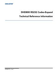
INSTALLATION TO SOLID CONCRETE OR CINDER BLOCK• When installing wall mounts onto cinder blocks, verify that you have a minimum of 1-3/8" (35 mm) of actual concrete thickness in the hole to be used for the concreteanchors. Do not drill into mortar joints. Be sure to mount in a solid part of the block,generally 1" (25 mm) minimum from the side of the block. Cinder block must meetASTM C-90 specifications. It is suggested that a standard electric drill on slow settingis used to drill the hole instead of a hammer drill to avoid breaking out the back ofthe hole when entering a void or cavity.• Concrete must be a minimum of 2000 psi density. Lighter density concrete may nothold the concrete anchor.• Make sure that the wall will safely support 4 times the combined load of theequipment and all attached hardware and components.• Tighten screws so that the wall plate is firmly attached. Never tighten in excess of 80in lbs (9Nm).• Always attach concrete expansion anchors directly to load-bearing concrete.• Never attach concrete expansion anchors to concrete covered with plaster, drywall,or other finishing material. If mounting to concrete surfaces covered with a finishingsurface is unavoidable, the finishing surface must be counter bored, as shown in theimage below. Make sure concrete anchors do not pull away from the concrete whentightening screws. If plaster/drywall is thicker than 5/8" (16 mm), custom fastenersmust be supplied by the installer.<strong>Mount</strong>ing to concrete surface with a finishing surfaceCUTAWAY VIEWwallplateplaster/drywallconcreteconcrete6 of 22 <strong>ML10</strong>/<strong>MP10</strong> <strong>LCD</strong> <strong>Video</strong> <strong>Wall</strong> <strong>Mount</strong> <strong>Instruction</strong> <strong>Sheet</strong>020-100726-05 Rev. 1 (07-2013)
1. Make sure that the pull out mount assembly is level – use it as a template to mark 4 mountingholes.2. Drill four 1/4” (6 mm) diameter holes to a minimum depth of 2.5” (64 mm).3. Insert anchors into the holes flush with the wall.4. Place the pull out mount assembly over the anchors and secure it with four #14 x 2.5” screws, andfender washers.5. Level and then tighten all fasteners.Landscape OrientationSolid concreteAnchorsCinder blockFenderwashers#14 x 2.5”screws*Pull out mount assembly* Make sure there is a minimum 16” (406.4 mm) horizontal distance between the #14 x2.5” screws.Portrait OrientationSolid concreteAnchorsCinder blockFenderwashers#14 x 2.5”screws*Pull out mount assemblyconcretesurfaceEDrill holes and insert anchors (E).FG HPlace plate (F) over anchors (G) and secure with screws (H).Tighten all fasteners.<strong>ML10</strong>/<strong>MP10</strong> <strong>LCD</strong> <strong>Video</strong> <strong>Wall</strong> <strong>Mount</strong> <strong>Instruction</strong> <strong>Sheet</strong> 7 of 22020-100726-05 Rev. 1 (07-2013)
INSTALLATION TO F100 FRAMEVerify that the combined load of the equipment and all attachedhardware and components do not exceed the maximum load, as specified in the P100Pedestal and F100 Frame Installation Manual (P/N: 020-100734-xx).1. Make sure all components within the video wall are level, starting with the P100 Pedestal. If thefloor surface is not level adjust the feet on the pedestal. For details, see P100 Pedestal and F100Frame Installation Manual (020-100734-xx).2. Install the F100 Frame onto the pedestal. See P100 Pedestal and F100 Frame InstallationManual (020-100734-xx).NOTE: If the F100 Frame is used as stand alone unit it must be leveled before securing the wallmount.3. Before installing the wall mount use a standard level to check alignment on the horizontal andvertical edge of the frame.4. Position the wall mount within the center of the frame, aligning it with the mounting holes.8 of 22 <strong>ML10</strong>/<strong>MP10</strong> <strong>LCD</strong> <strong>Video</strong> <strong>Wall</strong> <strong>Mount</strong> <strong>Instruction</strong> <strong>Sheet</strong>020-100726-05 Rev. 1 (07-2013)
5. Tighten the wall mount to the F100 Frame using the 4 M6 screws. Never tighten in excess of 80 inlbs(9Nm).Front ViewF100 frame<strong>Wall</strong> mountM6 screw (1 of 4)*Back View* M6 screws provided with F100 frame hardware kit (P/N: 000-102673-xx6. For good screen planarity within a video wall adjust the top knob of the adapter bracket to achievea 5 mm (0.19”) gap.<strong>ML10</strong>/<strong>MP10</strong> <strong>LCD</strong> <strong>Video</strong> <strong>Wall</strong> <strong>Mount</strong> <strong>Instruction</strong> <strong>Sheet</strong> 9 of 22020-100726-05 Rev. 1 (07-2013)
7. Adjust the bottom knob of the adapter bracket to achieve a 10 mm (0.39”) gap. If furtheradjustment is required, leave a 1 mm (0.04”) minimum clearance to allow the bracket to be easilyreleased.8. <strong>Mount</strong> the adapter bracket and use a level to check whether or not it is flush.10 of 22 <strong>ML10</strong>/<strong>MP10</strong> <strong>LCD</strong> <strong>Video</strong> <strong>Wall</strong> <strong>Mount</strong> <strong>Instruction</strong> <strong>Sheet</strong>020-100726-05 Rev. 1 (07-2013)
11. To avoid damage to the display it is advised to leave a minimum 1 mm (0.04”) gap so the weightof the panels do not rest on the panels underneath. It may be necessary to re-adjust the verticalposition to prevent this.12. Always adjust the X position of panels individually versus pushing an entire row left to right. Forexample, if you are constructing a 3x3 video wall push the panels individually from the right andleft sides, towards the center of the wall.12 of 22 <strong>ML10</strong>/<strong>MP10</strong> <strong>LCD</strong> <strong>Video</strong> <strong>Wall</strong> <strong>Mount</strong> <strong>Instruction</strong> <strong>Sheet</strong>020-100726-05 Rev. 1 (07-2013)
ATTACH ADAPTER BRACKETS TO DISPLAY13. Attach the adapter brackets to the back of the display using 4 M6 x 12 mm socket pin screws witha nylon shoulder washer, or 4 M8 x 15 mm socket pin screws, as shown below.NOTE: The hardware to attach the dedicated plates to the mount are included with the dedicatedplates.Landscape OrientationDisplayWasherSocket pin screwMAX VESA-700 mmMIN VESA-200 mmAdapter brackets400 mm 300 mm 200 mm PLPPortrait OrientationAdapter bracketsDisplayWasherSocketpin screw600 mm400 mm300 mm 200 mm MAX VESA-400 mmMIN VESA-200 mm<strong>ML10</strong>/<strong>MP10</strong> <strong>LCD</strong> <strong>Video</strong> <strong>Wall</strong> <strong>Mount</strong> <strong>Instruction</strong> <strong>Sheet</strong> 13 of 22020-100726-05 Rev. 1 (07-2013)
ATTACH ADAPTER BRACKETS TO DISPLAY CARRIAGE14. Slide the adapter brackets into position. Loosely fasten in place using the security screw, as shownbelow.NOTE: Once the display is located in the desired position (±2”/50.8 mm from center), tighten thesecurity screws using a 4 mm allen wrench to lock it in place.Landscape OrientationDisplay carriageAdapter bracketAdapter bracketSecurity screwPortrait OrientationDisplay carriageAdapter bracketAdapter bracketSecurity screw14 of 22 <strong>ML10</strong>/<strong>MP10</strong> <strong>LCD</strong> <strong>Video</strong> <strong>Wall</strong> <strong>Mount</strong> <strong>Instruction</strong> <strong>Sheet</strong>020-100726-05 Rev. 1 (07-2013)
PULL OUT MOUNT ASSEMBLY ADJUSTMENT15. Use the illustrations below to determine the position of the display. Each knob can be adjustedindependently for fine tuning adjustments. Turn knob clockwise to raise side. Turn knob counterclockwiseto lower side.PortraitLandscapeUPDOWNUPDOWNROTATE LEFTROTATE RIGHTROTATE LEFTROTATE RIGHT<strong>ML10</strong>/<strong>MP10</strong> <strong>LCD</strong> <strong>Video</strong> <strong>Wall</strong> <strong>Mount</strong> <strong>Instruction</strong> <strong>Sheet</strong> 15 of 22020-100726-05 Rev. 1 (07-2013)
ADAPTER BRACKET ADJUSTMENT16. Reference the following 2 images for portrait and landscape to determine the displays position.Each knob can be adjusted independently for fine tuning adjustments. Turn knob clockwise toraise side. Turn knob counter-clockwise to lower side.Adapter Bracket Adjustment – PortraitIN OUT TILT FORWARDBACKBACKBACKTILT BACKWARD TILT RIGHT TILT LEFTBACK BACK BACK16 of 22 <strong>ML10</strong>/<strong>MP10</strong> <strong>LCD</strong> <strong>Video</strong> <strong>Wall</strong> <strong>Mount</strong> <strong>Instruction</strong> <strong>Sheet</strong>020-100726-05 Rev. 1 (07-2013)
Adapter Bracket Adjustment – LandscapeIN OUT TILT FORWARDBACK BACK BACKTILT BACKWARD TILT RIGHT TILT LEFTBACK BACK BACK<strong>ML10</strong>/<strong>MP10</strong> <strong>LCD</strong> <strong>Video</strong> <strong>Wall</strong> <strong>Mount</strong> <strong>Instruction</strong> <strong>Sheet</strong> 17 of 22020-100726-05 Rev. 1 (07-2013)
CABLE MANAGEMENT17. Display cables can be routed through the top or bottom of the pull out mount assembly.NOTES: 1) Use the mesh sleeve and cable ties for cable management. 2) The cable ties and cablemanagement slots on the pull out mount assembly can be used to secure the display cables.Cable Management - PortraitCable management slotsDetail 3Cable Management - LandscapeCable management slotsDetail 318 of 22 <strong>ML10</strong>/<strong>MP10</strong> <strong>LCD</strong> <strong>Video</strong> <strong>Wall</strong> <strong>Mount</strong> <strong>Instruction</strong> <strong>Sheet</strong>020-100726-05 Rev. 1 (07-2013)
OPEN AND CLOSE PULL OUT MOUNT ASSEMBLYNOTICE: To avoid damaging the <strong>LCD</strong> panel always release both locking tabs at the same time andmove the panel forwards evenly.18. Release the locking tab to open the pull out mount assembly. Push or pull up on the locking tab, asshown in the illustration below.Pull Out <strong>Mount</strong> Assembly - PortraitPULL UPLockingTabLocking TabPUSH UPPull Out <strong>Mount</strong> Assembly - LandscapePULL UPLockingTabLocking TabPUSH UP<strong>ML10</strong>/<strong>MP10</strong> <strong>LCD</strong> <strong>Video</strong> <strong>Wall</strong> <strong>Mount</strong> <strong>Instruction</strong> <strong>Sheet</strong> 19 of 22020-100726-05 Rev. 1 (07-2013)
OPEN ADAPTER BRACKETSNOTICE: Two people are required when opening the adapter brackets, one to release the left-siderelease cord and the other the right-side release cord.19. Open the adapter brackets by pulling down on the long back release cords while pulling the bottomof the display away from the wall. Once the back release cords are pulled, the kick stand willengage.Open Adapter Brackets - PortraitDisplay NotShown for ClarityAdapter bracketKickStandAdapter bracketPull down backrelease cords (long)Open Adapter Brackets - LandscapeDisplay NotShown for ClarityAdapter bracketKickStandAdapter bracketPull down backrelease cords (long)20 of 22 <strong>ML10</strong>/<strong>MP10</strong> <strong>LCD</strong> <strong>Video</strong> <strong>Wall</strong> <strong>Mount</strong> <strong>Instruction</strong> <strong>Sheet</strong>020-100726-05 Rev. 1 (07-2013)
CLOSE ADAPTER BRACKETSNOTICE: Take caution when closing the adapter brackets to ensure the <strong>LCD</strong> panel is not damaged.Gently guide it back into place as you close the brackets.20. You may need to slightly pull the display away from the wall to release the kick stand.21. Close the adapter brackets by pulling down on the short front release cords, as shown below. Oncethe short cords are pulled, the kick stand will disengage.Close Adapter Brackets - PortraitDisplay NotShown for ClarityAdapter bracketAdapter bracketKickStandPull down frontrelease cords (short)Close Adapter Brackets - LandscapeDisplay NotShown for ClarityAdapter bracketAdapter bracketKickStandPull down frontrelease cords (short)<strong>ML10</strong>/<strong>MP10</strong> <strong>LCD</strong> <strong>Video</strong> <strong>Wall</strong> <strong>Mount</strong> <strong>Instruction</strong> <strong>Sheet</strong> 21 of 22020-100726-05 Rev. 1 (07-2013)
SECURE PULL OUT MOUNT ASSEMBLY (OPTIONAL)To prevent the locking tabs from releasing, secure using 2 M5 x 10 mm socket pin type-F screws.Landscape Orientationtype-FscrewLocking tabPortrait Orientationtype-FscrewLocking tab22 of 22 <strong>ML10</strong>/<strong>MP10</strong> <strong>LCD</strong> <strong>Video</strong> <strong>Wall</strong> <strong>Mount</strong> <strong>Instruction</strong> <strong>Sheet</strong>020-100726-05 Rev. 1 (07-2013)