Full integration of FURUNO Radar and an ENC
Full integration of FURUNO Radar and an ENC
Full integration of FURUNO Radar and an ENC

You also want an ePaper? Increase the reach of your titles
YUMPU automatically turns print PDFs into web optimized ePapers that Google loves.
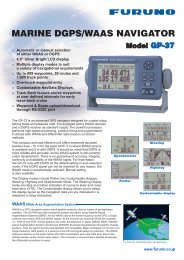
<strong>Full</strong> <strong>integration</strong> <strong>of</strong> <strong>FURUNO</strong> <strong>Radar</strong> <strong><strong>an</strong>d</strong> <strong>an</strong> <strong>ENC</strong>display system into a single unit for a new level<strong>of</strong> navigation safety <strong><strong>an</strong>d</strong> efficiencyProduct R<strong>an</strong>geFCR-2117:FCR-2127:FCR-2817:FCR-2827:FCR-2137S:FCR-2837S:FCR-2827W:FCR-2837SW:X-b<strong><strong>an</strong>d</strong>, 12 kW, TR upX-b<strong><strong>an</strong>d</strong>, 25 kW, TR upX-b<strong><strong>an</strong>d</strong>, 12 kW, TR upX-b<strong><strong>an</strong>d</strong>, 25 kW, TR upS-b<strong><strong>an</strong>d</strong>, 30 kW, TR upS-b<strong><strong>an</strong>d</strong>, 30 kW, TR upX-b<strong><strong>an</strong>d</strong>, 25 kW, TR downS-b<strong><strong>an</strong>d</strong>, 30 kW, TR down<strong>Radar</strong>/ARPAECDISEthernet100 Base-TX<strong>Radar</strong> echoEthernet10 Base-TSensor dataChart <strong>Radar</strong>ECDISCrucial navigation data obtainedfrom each <strong>of</strong> the onboard sensorsc<strong>an</strong> be displayed onto the <strong>Radar</strong>,ECDIS as well as Chart <strong>Radar</strong>displays, utilizing Ethernet-basednetworking technology by whichhigh-speed <strong><strong>an</strong>d</strong> stable data flowis possible. This networkingcapability allows operators tochoose either a single stationsystem or a total IntegratedNavigation System (INS).Black Box available with 2117/2127/2137SSensorsEchoSounderWith optional pedestalGPSDopplerSonarWith optional mounting bracket<strong><strong>an</strong>d</strong> connection st<strong><strong>an</strong>d</strong>R<strong>an</strong>gePresentation modeOwn ship'sinformationRoute pl<strong>an</strong>ning <strong><strong>an</strong>d</strong> route monitoring facilitiesWide variety <strong>of</strong> warning facilities contribute tosafer <strong><strong>an</strong>d</strong> more efficient navigationGrounding warnings, safe depth contoursChart database loaded <strong><strong>an</strong>d</strong> updated usingCD-ROMsSharing <strong>of</strong> route with ECDISMeets DNV NAUT-AW RequirementsUtilizes adv<strong>an</strong>ced signal processingtechnique to achieve outst<strong><strong>an</strong>d</strong>ing detectionin rough seasTarget data from ARPA radar <strong><strong>an</strong>d</strong> AIStr<strong>an</strong>sponder to aid in collision avoid<strong>an</strong>ceUp to 100 ARPA targets c<strong>an</strong> be tracked <strong><strong>an</strong>d</strong>displayedUp to 1500 AIS targets c<strong>an</strong> be displayedHigh-resolution LCD provides crisp radar imagesCompatible with IHO S-57 Edition 3.0/3.1Integration into total navigation networkINS VOYAGERBlack Box system configuration allows use <strong>of</strong><strong>FURUNO</strong> or commercial monitorsThis series <strong>of</strong> radar complies with the following IMO <strong><strong>an</strong>d</strong> IEC regulations: IMO A.694(17) IMO A.813(19) IMO A.820(19) IMO A.823(19) IMO MSC.36(63) IMO MSC.64(67) Annex 4 IMO MSC 191(79) IMO MSC 192(79) SN/Circ 217 IEC 60936-1 ed 1.1 Shipborne radar IEC 60936-2 ed 1.0 HSC radar IEC 60936-3 ed 1.0 Chart radar IEC 60936-5 Use <strong><strong>an</strong>d</strong> displayAIS inforamation IEC 60872-1 ed 1.0 ARPA IEC 60872-2 ed 1.0 ATA IEC 61993-2 ed 1.0 AIS IEC 60945 ed 4.0 General requirements IEC 61162-1 ed 3.0 Digital interface IEC 61162-2 ed 1 Digital interface IEC 62388 ed 1.0 IEC 62288 ed 1.0Shipborne radarPresentation <strong>of</strong>navigation-relatedinformationHeading lineOwn Ship's markerEBL boxChart <strong>Radar</strong> is <strong>Radar</strong> that c<strong>an</strong> display electronic charts(vector charts) together with the radar echo. Chart <strong>Radar</strong>is required by DNV for notation <strong>of</strong> NAUT-AW <strong><strong>an</strong>d</strong>NAUT-OSV. The Chart <strong>Radar</strong> FCR-21x7/28x7 seriesfeatures total <strong>integration</strong> <strong>of</strong> ARPA <strong>Radar</strong> <strong><strong>an</strong>d</strong> <strong>ENC</strong> DisplaySystem into a single unit. While retaining the full functions<strong>of</strong> <strong>FURUNO</strong> ARPA <strong>Radar</strong> FAR-21x7/28x7 series, theFCR-21x7/28x7 simult<strong>an</strong>eously displays radar images,with <strong>an</strong> <strong>ENC</strong>. The FCR-21x7/28x7 delivers a variety <strong>of</strong>display modes including <strong>Radar</strong>, ECDIS* <strong><strong>an</strong>d</strong> Chart <strong>Radar</strong>.*currently the FCR-21x7/28x7 c<strong>an</strong> not substitute ECDIS.The Chart <strong>Radar</strong> is a new core component <strong>of</strong> the<strong>FURUNO</strong> INS VOYAGER. When integrated into INS,route-monitoring c<strong>an</strong> be performed both on ECDIS <strong><strong>an</strong>d</strong>Chart <strong>Radar</strong> screens. A chart is overlaid on the radarimage, providing data observation stress-free.Pl<strong>an</strong>ned routeRoute monitoringdataUTC (coordinated universal time)Cursor information,Dist<strong>an</strong>ce <strong><strong>an</strong>d</strong> bearing betweenown ship <strong><strong>an</strong>d</strong> cursorEBLSuperb target detection in all climatic conditions is achievedby <strong>FURUNO</strong>’s sophisticated signal processing techniques.With full-featured ARPA, other ships’ movements aretracked <strong><strong>an</strong>d</strong> their CPA/TCPA are displayed. When thetargets are coming close to own ship, audio <strong><strong>an</strong>d</strong> visualalarms are generated to notify the navigator. Also, two guardzones c<strong>an</strong> be set to enh<strong>an</strong>ce monitoring <strong>of</strong> specific areasaround the vessel. When <strong>an</strong>y target, such as a ship <strong><strong>an</strong>d</strong>l<strong><strong>an</strong>d</strong>mass enters into the guard zone, audio <strong><strong>an</strong>d</strong> visualalarms are activated to notify the navigator. These alarmfunctions are very useful tools for executing safe <strong><strong>an</strong>d</strong>efficient navigation.The FCR-21x7/28x7 consists <strong>of</strong> <strong>an</strong> <strong>an</strong>tenna unit, processorunits, a display unit <strong><strong>an</strong>d</strong> a control unit. A high-resolution LCD(20" for FCR-21x7 series <strong><strong>an</strong>d</strong> 23" for FCR-28x7 series)presents clear radar images together with chart display.
Target TrailsThe target trails feature generates a monotone orgradual shading afterglow on radar targets on the display.The trails are useful for showing own ship movement<strong><strong>an</strong>d</strong> other ship tracks in <strong>an</strong>y situation at sea. True* orRelative echo trail is available in Relative Motion. (onlyTrue echo trail is selectable in True Motion) Trails remainon the screen, when ch<strong>an</strong>ging modes.*Heading sensor requiredARPA/AISFunction <strong>of</strong> FCR-21x7 series / FCR-28x7 seriesTargets automaticallyacquiredAIS-equipped targetselected for data readingUser ChartOwn ship data cellDATA CellARPA&AISInformationDATA Cell 1Route Pl<strong>an</strong>InformationDATA Cell 2CourseInformationLinesMarksOperator c<strong>an</strong> place points, lines, letter/number, symbols,areas <strong><strong>an</strong>d</strong> other indicators onto the radar display <strong><strong>an</strong>d</strong> theelectronic chart. The radar display <strong><strong>an</strong>d</strong> electronic chartwith those indicators c<strong>an</strong> be used to highlightsafety-related information such as position <strong>of</strong> buoys, lighthouses, wrecks <strong><strong>an</strong>d</strong> others. The areas set on these usercharts c<strong>an</strong> act as guard zones to notify <strong>of</strong> <strong>an</strong>y adversesituation.Guard ZonesSymbols for ARPAPastpositionsInitial stageECDIS ModeStatus bar• Presentation mode• Operation Mode• Chart Scale• Data displayedA vector appearsto show a trend <strong>of</strong>movement.Function <strong>of</strong> FCR-21x7 series / FCR-28x7 seriesGuard ZonesSteady tracking CPA alarm Lost target(Flashing)Automatic Acquisition ZoneTwo automatic acquisition zones may be set in a sectorform. They also act as suppression zones, avoidingunnecessary overloading to the processor <strong><strong>an</strong>d</strong> clutter bydisabling automatic acquisition <strong><strong>an</strong>d</strong> tracking outside them.Targets in <strong>an</strong> automatic acquisition zone are shown with<strong>an</strong> inverse tri<strong>an</strong>gle. The operator c<strong>an</strong> m<strong>an</strong>ually acquireimport<strong>an</strong>t targets without restriction.Guard Zones <strong><strong>an</strong>d</strong> Anchor Watch ZoneGuard Zones generate visual <strong><strong>an</strong>d</strong> audible alarms whentargets enter the operator set zones. One <strong>of</strong> the Guard Zonesmay be used as <strong>an</strong> <strong>an</strong>chor watch to alert the operator whenown ship or targets drift away from the set zone.CPA AlarmThe target tracking symbol ch<strong>an</strong>ges to a tri<strong>an</strong>gle when itspredicted course (vector) violates the operator setCPA/TCPA. The operator c<strong>an</strong> readily ch<strong>an</strong>ge the vectorlengths to evaluate the target movement trend.Past Position DisplayThe ARPA displays equally time-spaceddots marking the past positions <strong>of</strong> <strong>an</strong>ytargets being tracked. A new dot is addedduring preset time intervals until the presetnumber is reached. AIS also displays pastposition dots.Own ship’s information• Heading• Speed• Course over ground (COG)• Speed over ground (SOG)• Own ship's positionTarget Association (Fusion)An AIS-equipped ship may be displayed by both AIS <strong><strong>an</strong>d</strong> ARPA symbols.This is because the AIS position is measured by a GPS navigator in L/Lwhile the ARPA target blip <strong><strong>an</strong>d</strong> data are measured by r<strong>an</strong>ge <strong><strong>an</strong>d</strong> bearingfrom own ship. When the symbols are within <strong>an</strong> operator-set criteria,the ARPA symbol is merged with the AIS symbol. The criteria isdetermined by the differences in r<strong>an</strong>ge, bearing, course, speed, etc.Symbols for AISAIS COG/SOG vector ch<strong>an</strong>ges its length withspeed. ROT mark is viewable at the Headingline vector tip when a target ship is equippedwith a <strong>FURUNO</strong> satellite compass SC-50/110or gyrocompass which c<strong>an</strong> talk in ROT serialsentence.SOG (Speed over Ground) <strong><strong>an</strong>d</strong>COG (Course over Ground) vector *1Past positions*1 = Vector shows STW(speed thru water) <strong><strong>an</strong>d</strong>CSE (course) when watertracking mode isselected at the radar.DATA Cell 3Cursor dataData DisplayWhen <strong>an</strong>y mark on the electronic chart isselected, related information about theobject such as a buoy, lighthouse, sunkenvessel, etc., will be shown in the data cell.Additionally, other navigational informationincluding both own ship’s navigational, aswell as other ship’s information, from ARPAc<strong>an</strong> also be presented.Turning direction(ROT)Heading line#Sleeping AIS TargetSelected Target# = If there is noheading data,the line points inActivated Target direction <strong>of</strong> COG. Lost Target D<strong>an</strong>gerous TargetHeadingOwn ship’s markerAIS symbolPl<strong>an</strong>ned routeWTP(Waypoint)BuoyAIS information• Name • Course• IMO MMSI number • CPA• TCPA • Position• Speed • r<strong>an</strong>ge, etc.Route pl<strong>an</strong>ningThe operators c<strong>an</strong> pl<strong>an</strong> <strong><strong>an</strong>d</strong>determine the precise route withease, while studying the chart dataon the screen. A route c<strong>an</strong> be alteredin minute detail, <strong><strong>an</strong>d</strong> the ch<strong>an</strong>gedroute c<strong>an</strong> be saved for later use.
Specification <strong>of</strong> FCR-21x7 series / FCR-28x7 seriesSystem ConfigurationAntenna Radiators1. Type Slotted waveguide array2. Beamwidth <strong><strong>an</strong>d</strong> sidelobe attenuationRadiator TypeLengthBeamwidth(H)Beamwidth(W)Sidelobe (within 10°)Sidelobe (outside 10°)3. RotationX-B<strong><strong>an</strong>d</strong>RotationGear BoxS-B<strong><strong>an</strong>d</strong>RotationGear BoxRF Tr<strong>an</strong>sceiver1. FrequencyX-b<strong><strong>an</strong>d</strong>:S-b<strong><strong>an</strong>d</strong>:2. Output powerOutput PowerTr<strong>an</strong>sceiverX-B<strong><strong>an</strong>d</strong>9410 MHz ±30 MHz3050 MHz ±30 MHzS-B<strong><strong>an</strong>d</strong>XN-20AF6.5 ft1.23°20°-28 dB-32 dBXN-24AF8 ft0.95°20°-28 dB-32 dBSN-30AF10 ft2.3°25°-24 dB-30 dBSN-36AF12 ft1.8°25°-24 dB-30 dBS-b<strong><strong>an</strong>d</strong> 10 ft radiator usable for <strong>an</strong> HSC24 rpm 42 rpmRSB-096/103RSB-09721/26 rpmRSB-098/099/104/105FCR-2117/281712 kWRTR-078FCR-2127/282725 kWRTR-079FCR-2827W25 kWRTR-08145 rpmRSB-100/101/102FCR-2137S/2837S FCR-2837SW30 kW 30 kWRTR-080 RTR-0823. Pulselength/PRRR<strong>an</strong>ge scale (nm) Pulselength (µs) PRR (Hz)0.125, 0.25 0.07 30000.5 0.07, 0.15 30000.75, 1.5 0.07, 0.15, 0.3 3000, 15003 0.15, 0.3, 0.5, 0.7 3000, 1500, 10006 0.3, 0.5, 0.7, 1.2 1500, 1000, 60012, 24 0.5, 0.7, 1.2 1000, 60048, 96 1.2 6004. I.F. 60 MHz, LinearB<strong><strong>an</strong>d</strong>width Short pulse: 40 MHzMiddle pulse: 10 MHz Long pulse: 3 MHzDisplay Unit23" color LCD (UXGA 1600 x 1200 pixels)470 (H) x 353 (V) mm, Effective display diameter: 340 mmEcho Color: Yellow, green or white in 32 levels20" color LCD (SXGA 1280 x 1024 pixels)400 (H) x 320 (V) mm, Effective display diameter: 308 mmEcho Color: Yellow, green or white in 32 levelsGeneral Characteristics1. Display modes<strong>Radar</strong>, ECDIS, Chart <strong>Radar</strong>2. R<strong>an</strong>ge scales <strong><strong>an</strong>d</strong> ring intervals (nm)R<strong>an</strong>ge*: .125, .25, .5, .75, 1.5, 3, 6, 12, 24, 48, 96Ring: .025, .05, .1, .25, .25, .5, 1, 2, 4, 8, 16* R<strong>an</strong>ge scales in the Chart <strong>Radar</strong> mode are selectable from .125 until 12 nm.3. Minimum r<strong>an</strong>ge25 m in heading direction on 0.25 nm r<strong>an</strong>ge scale4. R<strong>an</strong>ge discrimination25 m at 1.5 nm in heading direction on 1.5 nm r<strong>an</strong>ge scale5. R<strong>an</strong>ge ring accuracy+1 %6. Presentation modes**Head-Up, Course-Up, North-Up, North-Up TM, Head-Up TB,Course-Up TM** Only North-Up TM is available for the Chart <strong>Radar</strong> mode.7. Heading informationFuruno GPS compass SC-50/110 is a recommendableheading sensor as a backup <strong>of</strong> a gyrocompass. Confirm withyour Administrations.8. Parallel index lines1, 2, 3 or 6 lines (menu selectable)Usable ChartsIHO/S-57 ed3 vector chart, ARCS raster chart,C-MAP CM93 ed3, C-MAP CM-<strong>ENC</strong>Automatic Plotting1. Acquisition100 targets (e.g. m<strong>an</strong>ually 50, automatically 50)2. TrackingAutomatic tracking <strong>of</strong> all acquired targets in 0.1 to 32 nm3. Guard zone (Target Acquisition Area)Two guard zone, one <strong>of</strong> them 0.5 nm depth4. Trial m<strong>an</strong>euverDynamic or static, with selected delay time.AIS FUNCTIONS (Data input from AIS is required)1. SymbolsSleeping, Activated, D<strong>an</strong>gerous, Selected, Lost targets2. Number <strong>of</strong> targets1500 targets max.3. Data indicationBasic <strong><strong>an</strong>d</strong> exp<strong><strong>an</strong>d</strong>ed dataPOWER SUPPLY (specify when ordering)1. <strong>Radar</strong> Processor Unit100-115/220-230 VAC, 1ø, 50/60 Hz2. Chart Processor Unit100-230 VAC, 1ø, 50/60 Hz3. Display Unit100-230 VAC, 1ø, 50/60 Hz4. LAN Adaptor24 VDC5. Antenna Unit*FCR-2137S/2837S/2837SW:RSB-098/104 200 VAC, 3ø, 50 Hz; 220 VAC, 3ø, 60 HzRSB-099/105 380 VAC, 3ø, 50 Hz; 440 VAC, 3ø, 60 HzRSB-100 220 VAC, 3ø, 50 Hz (for HSC)RSB-101 220 VAC, 3ø, 60 Hz (for HSC)RSB-102 440 VAC, 3ø, 60 Hz (for HSC)* Power supply for X-b<strong><strong>an</strong>d</strong> radar is provided via a <strong>Radar</strong> Processor.EQUIPMENT LISTSt<strong><strong>an</strong>d</strong>ard1. Display Unit MU-201CE (FCR-21x7 series)MU-231CE (FCR-28x7 series)2. <strong>Radar</strong> Processor Unit RPU-0163. Chart Processor Unit EC-1000C4. Control Unit with 10 m cable<strong>Full</strong>-keyboard Control UnitTrackball Control UnitRCU-020RCU-015FEA(Specify when ordering)5. Antenna Unit with built-in perform<strong>an</strong>ce monitor6. Antenna cable RW-9600 15/30/40/50 m(Specify when ordering)7. HUB HUB-1008. Tr<strong>an</strong>sceiver Unit (FCR-2827W/FCR-2837SW only)9. Power Supply Unit PSU-007 (FCR-2137S/2837S only)10. St<strong><strong>an</strong>d</strong>ard Spare Parts <strong><strong>an</strong>d</strong> Installation MaterialsOption1. Remote Control Unit RCU-0162. Gyro Interface GC-103. B-Adapter for equipment with <strong>an</strong>alog interface4. Tr<strong>an</strong>sformer RU-1803/3305/5466/5693/65225. Junction Box RJB-0016. Antenna Cable RW-9600 (max. 100 m)7. H<strong><strong>an</strong>d</strong> Grip FP03-098408. Bracket FP03-09820 / 098309. Switching Hub HUB-10010. LAN Adapter EC-101011. LAN Cable 10/20/30 m12. Flash Mount Kit for Control Unit13. Connection St<strong><strong>an</strong>d</strong>SinglePowerSupplyUnitPSU-007200 VAC, 3 , 50 Hz*220 VAC, 3 , 60 Hz380 VAC, 3 , 50 Hz440 VAC, 3 , 60 HzMultiPowerSupplyUnitPSU-007200 VAC, 3 , 50 Hz*220 VAC, 3 , 60 Hz380 VAC, 3 , 50 Hz440 VAC, 3 , 60 HzAntenna Unit (Specify when ordering)For FCR-2137S/2837SSN-30AF/SN-36AFDisplay UnitMU-201CE/MU-231CE100-230 VACControl UnitAntenna Unit (Specify when ordering)For FCR-2137S/2837SSN-30AF/SN-36AFDisplay UnitMU-201CE/MU-231CE100-230 VACRCU-020orRCU-015FEARemote Control UnitRCU-016Control UnitRCU-020orRCU-015FEARemote Control UnitRCU-016Option or Shipyard SupplyPowerPerform<strong>an</strong>ceMonitorPM-51 (built-in)5 m10 mPerform<strong>an</strong>ceMonitorPM-51 (built-in)5 m10 m1.5 m1.5 mFor FCR-2837SWFor FCR-2837SW<strong>Radar</strong>Processor UnitRPU-016Gyro IntrfaceGC-10100-230 VACTr<strong>an</strong>sceiver UnitRTR-082HUBHUB-100Tr<strong>an</strong>sceiver UnitRTR-082<strong>Radar</strong>Processor UnitRPU-016Gyro IntrfaceGC-10100-230 VACHUBHUB-10015/30/40/50 mECIDSProcessor ChartUnitProcessor EC-1000CX UnitEC-1000C15/30/40/50 mChartProcessor UnitEC-1000C2nd ECDIS stationPerform<strong>an</strong>ceMonitorPM-51 (built-in)Perform<strong>an</strong>ceMonitorPM-51 (built-in)10/20/30 mEthernet10/20/30 mECDIS Processor UnitEC-1000C100-115/220-230 VACEthernet10/20/30 m100-115/220-230 VACFor FCR-2827WXN-20AF/XN-24AFTr<strong>an</strong>sceiver UnitRTR-081PrinterPP-510GyrocompassGPS CompassSC-50/110For FCR-2827WXN-20AF/XN-24AFHUBHUB-100Tr<strong>an</strong>sceiver UnitRTR-081GyrocompassGPS CompassSC-50/110PrinterPP-510Perform<strong>an</strong>ceMonitorPM-31 (built-in)LAN AdapterEC-1010Perform<strong>an</strong>ceMonitorPM-31 (built-in)LAN AdapterEC-1010*Up to two LANadapters connectable24 VDC<strong>Radar</strong>/ARPAFAR-21x7 seriesFAR-28x7 seriesWith 8 portsB AdapterEC-1020With 18 ports24 VDCWith 8 ports24 VDCFor FCR-2117/2127/2817/2827SerialOption or Shipyard SupplyPowerFor FCR-2117/2127/2817/2827* Up to four systemsc<strong>an</strong> be connectedSerialx8x8Perform<strong>an</strong>ceMonitorPM-31 (built-in)AISRoute BackupGPS NavigatorAnemometerEcho SounderLog/Dual Axis LogWater Temp IndicatorAlarmsPerform<strong>an</strong>ceMonitorPM-31 (built-in)AISRoute BackupGPS NavigatorAnemometerEcho SounderLog/Dual Axis LogWater Temp IndicatorAlarmsLog (200 p/nm)AlarmsECDISFEA-2107FEA-2807Analog Sensors


![Brochure [PDF/4.68 MB] - Furuno](https://img.yumpu.com/44137332/1/190x135/brochure-pdf-468-mb-furuno.jpg?quality=85)