SP301 Smart Valve Positioner - Spirax Sarco
SP301 Smart Valve Positioner - Spirax Sarco
SP301 Smart Valve Positioner - Spirax Sarco
You also want an ePaper? Increase the reach of your titles
YUMPU automatically turns print PDFs into web optimized ePapers that Google loves.
Introduction<br />
II
Introduction<br />
INTRODUCTION<br />
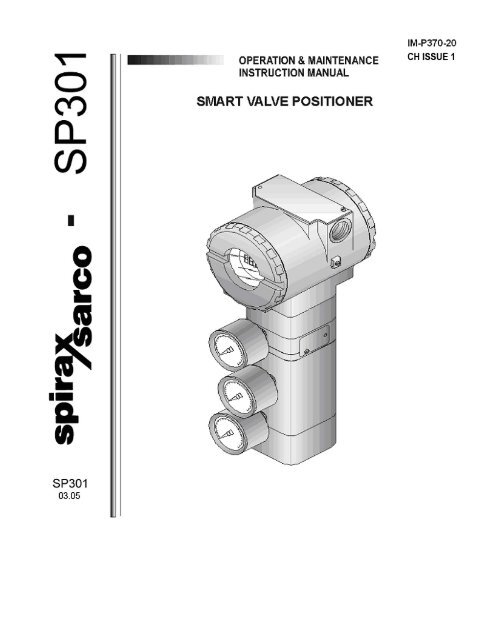
The <strong>SP301</strong> is a <strong>Spirax</strong> <strong>Sarco</strong> valve positioner for single acting (spring return) or double acting linear motion type control valves, e.g.<br />
Globe, Gate, Diaphragm, Pinch or Clamp; and rotary motion type control valves, e.g. Ball, Butterfly or Plug, when used with<br />
pneumatic type actuators, e.g. Diaphragm, Piston, Vane, or Bellows. It is based on a field-proven piezo flapper and non-contacting<br />
Hall-effect position sensor that provides reliable operation and high performance. The digital technology used in the <strong>SP301</strong> enabled<br />
the choice of several types of flow characterisations, an easy to use interface between the field and the control room, plus several<br />
interesting features that considerably reduce the installation, operation and maintenance costs.<br />
The <strong>SP301</strong>includes the following functions:<br />
* User defined valve characteristic<br />
* Local Adjustment - for travel, flow characterization, tuning, operation mode, indication, set point and PID parameters... and<br />
more…..<br />
* Password protection - three levels of user security for different functions.<br />
* Operation Counter - shows the number of changes in each function.<br />
* Self Setup - automatic calibration of valve travel and other parameters<br />
* Diagnostic – continuous monitoring of valve condition for preventive maintenance purposes.<br />
Get the best results from this <strong>SP301</strong> by carefully reading these instructions.<br />
III<br />
WARNING:<br />
Throughout the operation of the positioner, including self setup, do not touch the moving parts of the<br />
valve/actuator/positioner assembly as they may unexpectedly move under automatic control. ALWAYS disconnect<br />
supply air before touching any moving parts.
Introduction<br />
III<br />
NOTE<br />
This manual is compatible with version 2.XX, where 2 denote software version<br />
and XX software release. The indication 2.XX means that this manual is<br />
compatible with any release of software version 2.
SAFETY INFORMATION<br />
IMPORTANT<br />
SAFETY INFORMATION:<br />
PLEASE READ CAREFULLY<br />
Hazards to be considered when installing/using/maintaining<br />
1. Access<br />
Ensure safe access and if necessary a safe working platform before attempting to work on the product.<br />
Arrange suitable lifting gear if required.<br />
2. Lighting<br />
Ensure adequate lighting, particularly where detailed or intricate work is required e.g. electrical wiring.<br />
3. Hazardous liquids or gases in the pipeline<br />
Consider what is in the pipeline or what may have been in the pipeline at some previous time.<br />
Consider: flammable materials, substances hazardous to health, extremes of temperature.<br />
Safety Information<br />
4. Hazardous environment around the product<br />
Consider: explosion risk areas, lack of oxygen (e.g. tanks, pits) dangerous gases, extremes of temperature, hot surfaces, fire hazard<br />
(e.g. during welding), excessive noise, and moving machinery.<br />
ATEX certifications are available on demand for explosion proof housings (ATEX II2GEExdIICT6) and for intrinsically safe electronic<br />
circuits (ATEX II2GEExdIICT6).<br />
5. The system<br />
Consider the effect on the complete system of the work proposed. Will any proposed action (e.g. closing isolating valves, electrical<br />
isolation) put any other part of the system or any other workers at risk? Dangers might include isolation of vents or protective<br />
devices, or the rendering ineffective of controls or alarms.<br />
Ensure isolation valves are turned on and off in a gradual way to avoid system shocks.<br />
6. Pressure systems<br />
Ensure that any pressure is isolated and safely vented to atmospheric pressure.<br />
Consider double isolation (double block and bleed) and the locking and/or labelling of valve shut.<br />
Do not assume the system is de-pressurized even when the pressure gauge indicates zero.<br />
7. Temperature<br />
Allow time for temperature to normalise after isolation to avoid the risk of burns.<br />
8. Tools and consumables<br />
Before starting work ensure that you have suitable tools and/or consumables available. Use only genuine <strong>Spirax</strong> <strong>Sarco</strong> replacement<br />
parts.<br />
9. Protective clothing<br />
Consider whether any protective clothing is required, to protect against the hazards of, for example, chemicals, high/low<br />
temperature, noise, falling objects, dangers to eyes/face.<br />
10. Permits to work<br />
All works must be carried out or be supervised by a suitable competent person.<br />
Where a formal permit to work system is in force it must be complied with.<br />
Where there is no such system, it is recommended that a responsible person knows what work is going on and where necessary<br />
arrange to have an assistant whose primary responsibility is safety. Post warning notices if necessary.<br />
11. Electrical work<br />
Before starting work study the wiring diagram and wiring instructions and note any special requirements. Consider particularly:<br />
mains supply voltage and phase, local mains isolation, fuse requirements, earthing, special cables, cable entries/cable glands,<br />
electrical screening.<br />
12. Commissioning<br />
After installation or maintenance ensure that the system is fully functioning.<br />
Carry out tests on any alarms or protective devices.<br />
IV
Safety Information<br />
13. Disposal<br />
Unwanted equipment should be disposed of in a safe manner.<br />
14. Returning products<br />
Customers and stockists are reminded that under EC Health, Safety and Environmental Law, when returning products to <strong>Spirax</strong><br />
<strong>Sarco</strong> they must provide information on any hazards and the precautions to be taken due to contamination residues or mechanical<br />
damage which may present a health, safety and environmental risk.<br />
This information must be provided in writing including Health and Safety data sheets relating to any substances identified as<br />
hazardous.<br />
Note: The products supplied by <strong>Spirax</strong> <strong>Sarco</strong> are classified as components and are not generally affected by the<br />
Machinery Directive 89/392/EEC.<br />
V
Table of Contents<br />
Index<br />
1. INSTALLATION<br />
GENERAL .............................................................................................................................................................1.1<br />
MOUNTING...........................................................................................................................................................1.1<br />
PNEUMATIC CONNECTIONS..............................................................................................................................1.2<br />
ELECTRONIC HOUSING ROTATION..................................................................................................................1.5<br />
ELECTRIC WIRING ..............................................................................................................................................1.5<br />
RECOMMENDATIONS FOR AN INSTRUMENT AIR_SYSTEM ..........................................................................1.8<br />
2. OPERATION<br />
FUNCTIONAL DESCRIPTION - TRANSDUCER..................................................................................................2.1<br />
FUNCTIONAL DESCRIPTION - ELECTRONICS ................................................................................................2.2<br />
EEPROM...............................................................................................................................................................2.2<br />
THE LOCAL INDICATOR......................................................................................................................................2.4<br />
3. PROGRAMMING USING HAND-HELD TERMINAL<br />
HPC HART POCKET CONFIGURATOR ..............................................................................................................3.1<br />
CONFIGURATION ................................................................................................................................................3.6<br />
4. PROGRAMMING USING LOCAL ADJUSTMENT<br />
LOCAL PROGRAMMING TREE ...........................................................................................................................4.1<br />
ADJUSTABLE PARAMETERS .............................................................................................................................4.2<br />
SETUP (AUTO POSITIONING) ............................................................................................................................4.2<br />
PROCEDURE FOR CALIBRATION OF THE VALVE ...........................................................................................4.4<br />
5. MAINTENANCE PROCEDURES<br />
GENERAL .............................................................................................................................................................5.1<br />
DIAGNOSTICS WITH HAND_HELD TERMINAL..................................................................................................5.1<br />
DIAGNOSTICS WITHOUT HAND_HELD TERMINAL ..........................................................................................5.2<br />
DISASSEMBLY PROCEDURE .............................................................................................................................5.3<br />
RE-ASSEMBLY PROCEDURE.............................................................................................................................5.3<br />
INTERCHANGEABILITY.......................................................................................................................................5.4<br />
RETURN MATERIALS..........................................................................................................................................5.4<br />
EXPLODED VIEW ................................................................................................................................................5.5<br />
ACCESSORIES ....................................................................................................................................................5.6<br />
SPARE PARTS LIST.............................................................................................................................................5.6<br />
6. TECHNICAL CHARACTERISTICS<br />
FUNCTIONAL SPECIFICATIONS ........................................................................................................................6.1<br />
PERFORMANCE SPECIFICATIONS....................................................................................................................6.2<br />
PHYSICAL SPECIFICATIONS..............................................................................................................................6.2<br />
ORDERING CODE................................................................................................................................................6.3<br />
7. HAZARDOUS LOCATION INSTALLATION AND APPROVALS<br />
INSTALLATION AND OPERATION .....................................................................................................................7.1<br />
FM APPROVAL.....................................................................................................................................................7.2<br />
CSA APPROVAL ..................................................................................................................................................7.3<br />
NEMKO APPROVAL (ATEX, EEx d)....................................................................................................................7.4<br />
DMT APPROVAL (ATEX, EEx d [ia]) ...................................................................................................................7.5<br />
CONTROL DRAWINGS........................................................................................................................................7.6<br />
VI
Section 1<br />
General<br />
Mounting<br />
Installation<br />
The overall accuracy of measurement and control depends on several variables. Although the<br />
converter has an outstanding performance, proper installation is essential, in order to maximize its<br />
performance.<br />
Among all the factors which may affect converter accuracy, environmental conditions are the most<br />
difficult to control. There are, however, ways of reducing the effects of temperature, humidity and<br />
vibration.<br />
The <strong>SP301</strong> has a built-in temperature sensor to compensate for temperature variations. In the field,<br />
this feature minimizes the temperature variation effect.<br />
Locating the positioner in areas protected from extreme environmental changes can minimize<br />
temperature fluctuation effects.<br />
In warm climates, the positioner should be installed to avoid, as much as possible, direct exposure<br />
to the sun. Installation close to lines and vessels subjected to high temperatures should also be<br />
avoided.<br />
Use of sunshades or heat shields to protect the positioner from external heat sources should be<br />
considered, if necessary.<br />
Humidity is fatal to electronic circuits. In areas subjected to high relative humidity, the O-rings for the<br />
electronics cover must be correctly placed. Removal of the electronics cover in the field should be<br />
reduced to the minimum necessary, since each time it is removed the circuits are exposed to<br />
humidity. A humidity proof coating protects the electronic circuit, but frequent exposure to humidity<br />
may affect the protection provided. It is also important to keep the covers tightened in place. Every<br />
time they are removed, the threads are exposed to corrosion, since painting cannot protect these<br />
parts. Code approved sealing methods for conduit entering the positioner should be employed.<br />
Although the positioner is virtually insensitive to vibration, installation close to pumps, turbines or<br />
other vibrating equipment should be avoided.<br />
The <strong>SP301</strong> comes with the option of three built-in pressure sensors continuously monitoring the<br />
pressure at the air supply input and the two pneumatic outputs respectively.<br />
The mounting of positioner <strong>SP301</strong> will depend on actuator type: single acting (spring return) or<br />
double acting, and on actuator movement, if it is linear or rotary. Two supports are required for<br />
mounting: one for the magnet and the other for the positioner itself. <strong>Spirax</strong> <strong>Sarco</strong> can supply them<br />
both since they are specified in the order code (See page 5.2).<br />
Rotary Movement<br />
Install the magnet on the valve stem using the magnet support (See Figure 1.2).<br />
Install the positioner support on the actuator. Should the actuator be in accordance with standard<br />
VDI/VDE 5845, all you have to do is tighten the four screws with the lock washers on the standard<br />
support.<br />
For special supports, refer to specific instructions. After installing the support on the actuator, it is<br />
possible to mount positioner <strong>SP301</strong> on the support by means of the four screws with lock washers.<br />
Make sure that the arrow engraved on the magnet coincides with the arrow engraved on the<br />
positioner when the valve is in mid travel.<br />
Should the installation of the positioner or magnet be altered, or should there be any other<br />
modification, the positioner will require a recalibration.<br />
As to the type of valve action, refer to paragraph “pneumatic connections”.<br />
1.1
<strong>SP301</strong> – Operation and Maintenance Instruction Manual<br />
Pneumatic Connections<br />
1.2<br />
Linear Movement<br />
Install the magnet on the valve stem using the magnet support (See Figure 1.3).<br />
Install the positioner support on the actuator. The actuator support may be secured in place as per<br />
standard NAMUR/IEC 536-4 or in accordance with user specifications. Install the positioner on the<br />
support and tighten the four screws in the threaded holes located on the side opposite to the<br />
pressure gauges (Figure 1.3). Use lock washers in order to prevent screw slackening.<br />
Make sure that the support is not obstructing the exhaustion outlets.<br />
Make sure that arrow engraved on the magnet coincides with the arrow engraved on the positioner<br />
when the valve is in mid travel.<br />
Should the installation of the positioner or magnet be altered, or should there be any other<br />
modification, the positioner will require a re-calibration.<br />
Air supplied to the positioner <strong>SP301</strong> shall be quality instrument air, i.e., dry, clean and noncorrosive.<br />
Refer to the Instrument Society of America Standard entitled “Quality Standard for<br />
Instrument Air” (ISA S7.3). See “RECOMMENDATIONS FOR AN INSTRUMENT AIR SYSTEM” on<br />
page 1.8. It may be possible to provide suitably clean air by use of appropriate air filters – please<br />
consult <strong>Spirax</strong> <strong>Sarco</strong> for further information.<br />
Air supply pressure to the <strong>SP301</strong> shall be between 1.4 bar (20 psi) and 7 bar (100 psi). In case such<br />
requirements cannot be fulfilled, the use of an air pressure regulator is essential.<br />
Use a non-setting sealant on threads. Sealant like PTFE (Teflon) tape shall be avoided because<br />
they may fragment and eventually obstruct internal parts.<br />
<strong>Positioner</strong> <strong>SP301</strong> may be supplied with pressure gauges. There are ports provided for IN, OUT1<br />
and OUT2. Before connecting the pressure lines, make sure that all lines are de-pressurised.<br />
<strong>Valve</strong> positioner <strong>SP301</strong> has two pneumatic outputs. They work on opposite directions to open or<br />
close the valve.<br />
IMPORTANT:<br />
Should the <strong>SP301</strong> fail, for example, because of a power failure, the output identified as OUT1 (output 1)<br />
goes to nearly zero, while the output identified as OUT2 (output 2) goes to nearly the air supply pressure.<br />
Pneumatic connections are identified as IN (input) for the air supply, and OUT1 and OUT2 for<br />
Output 1 and Output respectively (See Figure 1.1). Use 1/4 NPT connections. Sealant may be used<br />
NPT threads. Connect the air supply tubing to the connection identified as IN. Make sure that the air<br />
supply pressure does not exceed the maximum rating accepted by the positioner or actuator – 7 bar<br />
(100 psi).<br />
The tubing used to connect the positioner <strong>SP301</strong> to the actuator shall be as short as possible.<br />
ATTENTION:<br />
Make sure that sealant does not enter in the positioner.<br />
There are five exhaust outputs in the <strong>SP301</strong>, all of them fitted with filters (See Figure 1.1).<br />
It is very important that such outputs are neither blocked nor obstructed, because the air must<br />
circulate freely.<br />
All filters shall be inspected to make sure they will not obstruct the outputs. Refer to Section 4 -<br />
Maintenance.<br />
Double Action - Air to Open (Fail Close)<br />
Connect Output 1 (OUT1) of the positioner to the input identified as OPEN in the actuator, and
Installation<br />
connect Output 2 (OUT2) of the positioner to the input CLOSE in the actuator (See Figure 1.1).<br />
Double Action - Air to Close (Fail Open)<br />
Connect Output 2 (OUT2) of the positioner to the input identified as OPEN in the actuator, and<br />
connect Output 1 (OUT 1) of the positioner to the input CLOSE of the actuator.<br />
Single Action<br />
Connect Output 1 (OUT1) of the positioner to the input of the actuator. Use a plug to block Output 2<br />
(OUT2). Figures 1.2 and 1.3 show the positioner in rotary and linear actuators.<br />
Fig 1.1 – <strong>SP301</strong> Dimensional Drawing<br />
1.3
<strong>SP301</strong> – Operation and Maintenance Instruction Manual<br />
1.4<br />
Fig. 1.2 – <strong>Positioner</strong> on the Rotary Actuator<br />
Fig. 1.3 – <strong>Positioner</strong> on the Linear Actuator
Electronic Housing Rotation<br />
Electric Wiring<br />
Installation<br />
The electronic housing can be rotated 360° in order to re-orientate the digital display. To rotate it,<br />
use the Housing Rotation Set Screw, see Figure 1.4.<br />
Figure 1.4 - Housing Rotation Set Screw<br />
Access the wiring block by removing the Electrical Connection Cover. This cover can be locked<br />
closed by the cover locking screw. To release the cover, rotate the locking screw clockwise. See<br />
figure 1.5.<br />
Fig. 1.5 – Cover Locking Screw<br />
The local indicator itself can also be rotated. See Section 5, Figure 5.2.<br />
Test terminals allow the user to measure the current in the 4 - 20 mA loop without cutting into the 4-<br />
20mA wiring, and communication terminals facilitate communication with the transmitter. To<br />
measure the mA signal, connect a multimeter set to read mA to the "0" and "�" terminals, and to<br />
communicate, use a HART configurator in the "COMM" and "0" terminals.<br />
For convenience there are two ground terminals: one inside the cover and one external, located<br />
close to the conduit entries.<br />
The wiring block has screws into which fork or ring-type terminals can be fastened. See Figure 1.6.<br />
1.5
<strong>SP301</strong> – Operation and Maintenance Instruction Manual<br />
1.6<br />
Fig. 1.6 – Wiring Block<br />
HAZARDOUS AREAS<br />
In hazardous areas with explosion proof requirements, the covers must be tightened at least 8<br />
turns. In order to avoid the penetration moisture or corrosive gases, tighten the "O" ’ring until<br />
feeling the “O” ring touching the housing. Then, tighten more 1/3 turn (120°) to guarantee the<br />
sealing. Lock the covers using the locking screw.<br />
In hazardous zones with intrinsically safe or non-incendive requirements, the circuit entity<br />
parameters and applicable installation procedures must be observed.<br />
Cable access to wiring connections is obtained by one of the two conduit outlets. Conduit<br />
threads should be sealed by means of code-approved sealing methods. The unused outlet<br />
connection should be plugged and sealed accordingly.<br />
Explosion proof, non-incendive and intrinsic safety certification are standard for <strong>SP301</strong>.<br />
Should other certifications be necessary, refer to the certification or specific standard for<br />
installation limitations.<br />
The Figure 1.7 – Conduit Installation Diagram shows the correct installation of the conduit, in order<br />
to avoid penetration of water or other substance, which may cause malfunctioning of the equipment<br />
.<br />
WIRES<br />
CORRECT<br />
Figure 1.7 - Conduit Installation Diagram.<br />
Use of twisted pair (22 AWG or greater) cables is recommended.<br />
Avoid routing signal wiring close to power cables or switching equipment.<br />
INCORRECT<br />
The <strong>SP301</strong> is protected against reverse polarity, and can withstand up to 50 mA without damage.<br />
The <strong>SP301</strong> connection may be done according to figures 1.8, 1.9 and 1.10.
Installation<br />
The Hand-Held Terminal can be connected to the communication terminals of the transmitter or at<br />
any point of the signal line by using the interface IF3 with alligator clips.<br />
It is also recommended to ground the shield of shielded cables at one end only. The non-grounded<br />
end must be carefully isolated.<br />
POWER SUPPLY<br />
GROUND THE SIGNAL LOOP AT ANY<br />
POINT OR LEFT IT UNGROUNDED<br />
CONFIGURATOR<br />
Fig. 1.8 – Wiring Diagram of the <strong>SP301</strong><br />
Connection of the <strong>SP301</strong> in multi-drop configuration should be done as in Figure 1.9. Note that a<br />
maximum of two positioners can be connected on the same line and that they should be connected<br />
in series.<br />
POWER SUPPLY<br />
OUTPUT<br />
GROUND THE SIGNAL LOOP AT ANY<br />
POINT OR LEFT IT UNGROUNDED<br />
CONFIGURATOR<br />
Fig. 1.9 – Wiring Diagram of <strong>SP301</strong> Connected in the SPIRAX SARCO Transmitter<br />
The <strong>SP301</strong> has an equivalent impedance of 550 Ohms. Make sure that the analog output (*)<br />
powering the positioner is capable to handle a voltage drop of 11 V for each positioner.<br />
1.7
<strong>SP301</strong> – Operation and Maintenance Instruction Manual<br />
1.8<br />
If you are using two positioners in series as e.g. working in split range, the resulting impedance will<br />
be 1100 Ohms. Therefore, the analog output should be capable to handle a voltage drop of 22V.<br />
POWER SUPPLY<br />
CONFIGURATOR<br />
Fig. 1.10 – Wiring Diagram for the <strong>SP301</strong> in Multi-drop Configuration
Recommendations for an Instrument Air System<br />
COMPRESSOR<br />
INTAKE<br />
COMPRESSOR<br />
OIL AND WATER<br />
MIST PREFILTER<br />
WITH DRAIN<br />
Installation<br />
Instrument air quality shall be superior to that of industrial compressed air. Humidity, airborne<br />
particles and oil will impair the instrument operation, either temporarily or permanently.<br />
As per standard ANSI/ISA S7.3 - Quality Standard for Instrument Air, instrument air shall the<br />
following characteristics:<br />
Dew point 10 o C below minimum plant temperature<br />
Size of particles (airborne) 3 µm (maximum)<br />
Oil content 1 ppm w/w (maximum)<br />
Contaminants Free from toxic flammable gases<br />
Standard ISA RP7.7 - Recommended Practice for Producing Quality Instrument Air contains general<br />
instructions for air production within the quality parameters defined in standard ANSI/ISA S7.3. This<br />
standard recommends that the compressor intake be located in an area free from process spills and<br />
fitted with and adequate filter. It also recommends the use of non-lubricated type compressors, in<br />
order to prevent air contamination by lubricating oil. Where lubricated type compressors are<br />
adopted, there shall be used means to make the air oil free.<br />
Figure 1.11 and 1.12 shows a typical system for Air Supply and Air Quality Conditioning.<br />
AFTERCOOLER<br />
CONDENSATE<br />
SEPARATOR<br />
WITH DRAIN<br />
Fig.1.11 – Air Quality Conditioning System<br />
AIR<br />
DRYER<br />
Fig.1.12 - Air Quality Conditioning System<br />
AIR RECEIVER<br />
WITH DRAIN<br />
DRY AIR<br />
AFTERFILTER<br />
1.9
<strong>SP301</strong> – Operation and Maintenance Instruction Manual<br />
1.10
Section 2<br />
Operation<br />
Functional Description - Transducer<br />
The main parts of the output module are the pilot, servo, Hall effect sensor and the output control<br />
circuit.<br />
The control circuit receives a digital setpoint signal from the CPU and a feedback signal from the<br />
Hall effect sensor.<br />
The pneumatic circuit is based on a well known and widely adopted technology.<br />
RESTRICTION<br />
PILOT<br />
DIAPHRAGM<br />
SPOOL<br />
DIAPHRAGM<br />
AIR SUPPLY<br />
SPOOL<br />
PILOT<br />
Fig. 2.1 – Schematic Pneumatic Transducer<br />
PIEZO VANE<br />
NOZZLE<br />
PILOT CHAMBER<br />
VENT 2<br />
OUTPUT 2<br />
OUTPUT 1<br />
VENT 1<br />
SPRING<br />
A piezoelectric disk is the flapper in the pilot stage. The flapper is deflected when the control circuit<br />
applies a voltage. A small stream of air flowing through the nozzle is obstructed causing an increase in<br />
pressure in the pilot chamber; this is called the pilot pressure.<br />
The pilot pressure is too low to be used directly, with low air flow rates, and for this reason it must be<br />
amplified in the servo section. The servo section includes a diaphragm in the pilot chamber and a<br />
smaller one in the spool chamber. The pilot pressure applies a force at the pilot chamber’s diaphragm,<br />
which, in the equilibrium state, will be equal to the force applied by the spool valve at the smaller<br />
diaphragm, which is in the spool chamber.<br />
Upon every position change caused by the positioner, the pilot pressure increases or decreases. Such<br />
change in pilot pressure causes an upward or downward valve travel, which alters the pressure at output<br />
1 and output 2, until a new balance is reached (new valve position).<br />
2.1
Operation<br />
Functional Description-Electronics<br />
EEPROM<br />
2.2<br />
Refer to the block diagram (Fig. 2.2). The function of each block is described below.<br />
A/D<br />
Receives the 4 - 20 mA signal and converts it in the digital format for the CPU.<br />
D/A<br />
Receives the signal from the CPU and converts it to an analog voltage proportional the desired position,<br />
used by the control.<br />
Control<br />
Controls the valve position according the data received from the CPU and the HALL effect sensor<br />
feedback.<br />
Hall Effect Sensor<br />
Measures the actual valve position and feeds back this data to the control and CPU.<br />
Temperature Sensor<br />
Measures the temperature of the Transducer Assembly.<br />
Pressure Sensors<br />
Measure the air supply pressure , and pressure at output 1 and output 2. Available for HART reading.<br />
Isolation<br />
Its function is to isolate the 4 - 20 mA signal from the piezoelectric signal.<br />
A non-volatile memory which stores configuration data as a backup, should the <strong>SP301</strong> main board be<br />
replaced<br />
,<br />
(CPU) Central Processing Unit, RAM, PROM and EEPROM<br />
The CPU is the intelligent portion of the positioner, being responsible for the management and operation<br />
of block execution, self-diagnostics and communication. The program is stored in PROM. For temporary<br />
storage of data there is a RAM. The data in the RAM is lost if the power is switched off, however the<br />
device also has a nonvolatile EEPROM where data that must be retained is stored. Examples of such<br />
data are calibration and valve configuration.<br />
Modem<br />
Modulates and demodulates communication signals on the current line. A “1” is represented by 1200 Hz<br />
and “0” by 2200 Hz. The frequency signal is symmetrical and does not affect the DC-level of the of the 4<br />
- 20 mA signal.<br />
Power Supply<br />
The positioner circuit receives supply from a 4 - 20 mA power supply, or takes power from the Loop Line<br />
to power the positioner circuit. This is, of course, limited to 3.8 mA.<br />
Display Controller<br />
Receives data from the CPU and drives the (LCD) Liquid Crystal Display.<br />
Local Adjustment<br />
Local adjustment is provided by means of two magnetically actuated switches with no external electric or<br />
mechanical contact, by using a magnetic screwdriver.<br />
Piezo Flapper Nozzle<br />
The unit flapper nozzle converts the movement of piezoelectric element into a pneumatic signal,to<br />
control pressure in the pilot chamber.<br />
Restriction<br />
The restriction and the nozzle form a pressure-divided circuit. Air is supplied to the nozzle through a<br />
restriction.<br />
Spool<br />
The spool ensures a quick valve positioning by providing a greater airflow than one provided by the<br />
restriction.<br />
NOTE<br />
The pressure sensor’s circuit board is optional.<br />
Sensor Selector: Select the sensor to be read from.
4 - 20mA<br />
Sensor IN: Measures air supply pressure.<br />
Sensor OUT1: Changes pressure in Outlet 1<br />
Sensor OUT2: Changes pressure in Outlet 2<br />
<strong>SP301</strong> – Operation and Maintenance Instruction Manual<br />
MAIN CIRCUIT BOARD DISPLAY<br />
SUPPLY<br />
POWER<br />
SUPPLY<br />
INPUT<br />
SUPPLY<br />
TRANSDUCER<br />
SENSOR<br />
SELECTOR<br />
TEMPERATURE<br />
SENSOR<br />
RESTRICTION<br />
PROM<br />
HART<br />
MODEM<br />
A/D<br />
CONVERTER<br />
VPIEZO<br />
PRESSURE SENSOR CIRCUIT BOARD<br />
READOUT<br />
SELECTOR<br />
CONTROL<br />
ISOLATION<br />
PIEZO<br />
FLAPPER<br />
NOZZLE<br />
SPOOL<br />
VALVE<br />
AIR SUPPLY<br />
SENSOR<br />
OUT1<br />
SENSOR<br />
OUT2<br />
LOCAL<br />
ADJUST<br />
CPU<br />
EEPROM<br />
RAM<br />
A/D<br />
HALL<br />
SENSOR<br />
CIRCUIT<br />
HALL<br />
SENSOR<br />
Fig. 2.2 - <strong>SP301</strong> Block Diagram<br />
D/A<br />
* OPTIONAL<br />
M<br />
A<br />
G<br />
N<br />
E<br />
T<br />
DISPLAY<br />
CONTROLLER<br />
P1<br />
P2<br />
VALVE<br />
ACTUATOR<br />
E<br />
S<br />
T<br />
M<br />
VALVE<br />
2.3
Operation<br />
The Local Indicator<br />
The local indicator is required for signaling and operation in local adjustment.<br />
Fig. 2.4 – Local Indicator<br />
2.4<br />
INDICATES THAT THE CONSTANT<br />
OUTPUT MODE IS ACTIVE<br />
Normal Indicator<br />
During normal operation, the <strong>SP301</strong> remains in the monitoring mode and the display indicates the valve<br />
position, either as a percentage or as a current readout. The magnetic tool activates the local<br />
programming mode, by inserting it in orifice Z on the housing.<br />
The possible configuration and monitoring operation are shown on Figure 2.3.<br />
Upon receiving power, the <strong>SP301</strong> initializes the position indication on the display, by showing model<br />
<strong>SP301</strong> and its software version (X.XX). In case the indication is higher than ±19999 it will be displayed<br />
as a two digit and an exponent.<br />
Monitoring<br />
During normal operation, <strong>SP301</strong> remains in the monitoring mode. Figure 2.4 shows the positioning.<br />
The display simultaneously shows the valve position readout and some other information.<br />
Normal display is interrupted when the magnetic tool is placed in orifice Z (Local Adjustment), entering<br />
the programming mode local adjustment.<br />
The above mentioned figure shows the result of tool insertion in orifices Z and S, which inform,<br />
respectively, movement and actuation of the selected options.<br />
VARIABLE FIELD<br />
INDICATES THE POSSIBILITY<br />
TO CHANGE / ADJUST<br />
VARIABLE / MODE<br />
Fig. 2.3 – Typical Normal Indicator<br />
FIX<br />
MD<br />
%<br />
INDICATES THAT THE LOCAL ADJUSTMENT<br />
MODE WILL BE ACCESSED<br />
READOUT IN PERCENTAGE<br />
UNIT AND FUNCTION FIELD
<strong>SP301</strong> – Operation and Maintenance Instruction Manual<br />
2.5
Section 3<br />
Programming Using Hand-Held Terminal<br />
HPC HART POCKET CONFIGURATOR<br />
Introduction<br />
HPC301 Software Installation<br />
<strong>Spirax</strong> <strong>Sarco</strong> <strong>SP301</strong> can be configured by hand using a held terminal together withsoftware by SMAR<br />
(HPC301).<br />
The HPC301 (HART® Pocket Configurator) is a Palm OS based software that runs in the Palm Operating<br />
System version 3.5 and later. The HPC301 Package comprises three parts:<br />
1. The communication interface, specifically the HPI311 (HART® Pocket Interface),<br />
2. The Palm OS based handheld computer, and<br />
3. The configuration software, specifically the HPC301 (HART® Pocket Configurator).<br />
The HPC301 software is compatible with most Palm handheld versions; this gives the user the flexibility<br />
to choose which handheld would be best suited for their purposes. Listed below are the three<br />
communication interfaces supported (refer to the HPI311 Reference Guide):<br />
HPI311-V - Compatible with Palm V/Vx.<br />
HPI311-III - Compatible with Palm IIIc, and VIIx. (Palm VIIx is available only in the USA.)<br />
HPI311-M5 - Compatible with Palm m125/130, m500/505/515 and i705. (Palm i705 is available only in the<br />
USA.)<br />
NOTE<br />
The configuration software is always the same independently of the interface or Palm<br />
handheld model chosen.<br />
To Install/Upgrade the HPC301 software:<br />
NOTE<br />
If you are unfamiliar with the Palm handheld and it’s<br />
associated terminology, read the manual that comes<br />
with your handheld to become familiar with its<br />
terminology and usage. Any Palm terminology used<br />
hereafter in this section will be denoted by italic font.<br />
1. Ensure the cradle is connected to your computer and the Palm Desktop software is installed.<br />
2. Exit all open programs.<br />
3. Start the setup program by double clicking on the HPC301.EXE file.<br />
4. When the HPC301 Installer menu appears, click the Next button to begin the installation procedure<br />
and follow the on screen instructions.<br />
5. Start the Hotsync Manager, if not already started.<br />
6. Insert your handheld in its cradle and press the HotSync button. The HPC301 application will<br />
automatically be installed into your Palm handheld.<br />
Now you should be able to see the HPC301 icon in the Palm Handheld (Figure 1).<br />
3.1
<strong>SP301</strong> – Operation and Maintenance Instruction Manual<br />
3.2<br />
Figure 1<br />
Starting the Software<br />
To start the HPC301 software:<br />
1. Tap the HPC301 icon. The following screen will appear:<br />
Figure 2<br />
2. Now select the device polling address by choosing an address from 0 to 15. Select a particular device<br />
address, a particular device tag, or a range of addresses.<br />
NOTE<br />
Please refer to the field devices’ operation manual for<br />
connection of the Configurator to the HART®<br />
Network.<br />
3. Tap the Poll button and the HPC301 will poll the network for the desired device. After execution of<br />
the Poll function, the list of polled devices found on the bus will be available (Figure 3).
Figure 3<br />
Programming Using Hand-Held Terminal<br />
4. Select the device from the list by tapping on it. The HPC301 will provide access to all functions<br />
available for this device. For instance, if the selected device is a <strong>SP301</strong>, the next screen shown<br />
would be Figure 4.<br />
Figure 4<br />
Registering the HPC301<br />
5. For further explanation of specific field device procedures, please refer to the instructions provided in<br />
the Appendix. If no instructions for the specific device are available, refer to the Generic device<br />
section.<br />
To register the HPC301, please send the information below to <strong>Spirax</strong> <strong>Sarco</strong> Italy by fax or e-mail. (*<br />
Required information.)<br />
To: <strong>Spirax</strong> <strong>Sarco</strong> Italy<br />
E-mail: davideradina@it.spiraxsarco.com;<br />
robertogiordano@it.spiraxsarco.com;<br />
Fax: +39 0362 4917 311<br />
User’s Information<br />
User Name:<br />
Title:<br />
Company Name:<br />
3.3
<strong>SP301</strong> – Operation and Maintenance Instruction Manual<br />
3.4<br />
Address:<br />
City: State: Zip Code:<br />
Phone: Fax:<br />
*E-mail:<br />
HPI311 Information<br />
*HPI311 model and serial number:<br />
Calibrating the Palm handheld screen<br />
NOTE<br />
Registered users receive technical support, early<br />
notification of product upgrades, and new product<br />
announcements.<br />
Sometimes when you try to tap the buttons or icons on your Palm screen, the handheld will activate the<br />
wrong feature. When this happens, it usually means that the Palm handheld screen needs to be<br />
calibrated. Please refer to the Frequently Asked Questions (tapping and writing problems) section of your<br />
Palm manual for calibration instructions.
CONFIGURATION<br />
Introduction<br />
NOTE:<br />
Programming Using Hand-Held Terminal<br />
Refer to the <strong>SP301</strong>'s Operation and Maintenance<br />
Instruction/Manual for detailed information of the<br />
topics described below.<br />
By means of the HART ® Configurator, the <strong>SP301</strong> firmware allows the following configuration features<br />
to be accessed:<br />
� <strong>Positioner</strong> identification and specification data.<br />
� Remote stroking.<br />
� Special characterization function according to a configurable 16-point curve.<br />
� Flow characterization (Linear, Equal Percentage, Quick Opening).<br />
� Monitoring of all device variables: input, setpoint output, deviation and output module temperature.<br />
� Diagnostic (Preventive Maintenance).<br />
� <strong>Positioner</strong> diagnosis and determining faults<br />
� PID Controller Configuration.<br />
� Device Configuration.<br />
� Equipment Maintenance.<br />
The operations, which take place between the configurator and the positioner do not interrupt the valve<br />
positioning, and do not disturb the output signal. The configurator can be connected on the same pair of<br />
wires as the 4-20 mA signal, up to 2 km away from the transmitter.<br />
NOTE:<br />
All HPC301 button sequences provided in this<br />
Appendix assume that you are starting from the<br />
main <strong>SP301</strong> menu (Figure 1). Refer to Starting the<br />
Software section of this manual to get to this<br />
position.<br />
3.5
<strong>SP301</strong> – Operation and Maintenance Instruction Manual<br />
3.6<br />
Figure 1<br />
MONITORING - Monit<br />
To Monitor the <strong>Positioner</strong> variables (Figure 2):<br />
1. From the main <strong>SP301</strong> menu, click the Monit button.<br />
Figure 2<br />
INFORMATION - Info<br />
To configure the Tag, Descriptor, Message and Date (Figure 3):<br />
1. From the main <strong>SP301</strong> menu, click the Info button.<br />
2. Enter the desired value(s) in the corresponding field(s).<br />
3. Click the Send button.
Figure 3<br />
CONFIGURATION - Conf<br />
SAFETY POSITION - Fail Safe<br />
Programming Using Hand-Held Terminal<br />
The valve position may be programmed to go to either: freeze in Last Value, go fully open (Open) or<br />
go fully closed (Close) should the failure occur (in a way that still allows the positioner to manipulate a<br />
output). In failure mode FAIL will also be indicated in the display.<br />
FLOW CHARACTERISATION - Function<br />
The desired flow characteristics may be changed using this function. E.g. if a valve with linear inherent<br />
flow characteristics is used and equal percentage applied flow characteristics is selected, the valve will<br />
operate as an equal percentage valve. The adjacent number is the rangeability of the valve. The<br />
rangeability of the valve may be found in the manufacturer’s documentation.<br />
To configure the Fail Safe (Safety Position), Function (Flow Characterization) and LCD Indic (Figure 4):<br />
1. From the main <strong>SP301</strong> menu, click the Conf button.<br />
2. Select the desired value(s).<br />
3. Click the Send button.<br />
Figure 4<br />
3.7
<strong>SP301</strong> – Operation and Maintenance Instruction Manual<br />
SETUP - Setup<br />
3.8<br />
To configure the Table points (Figure 5):<br />
1. From the main <strong>SP301</strong> menu, click the Conf -> Table button.<br />
2. Select the desired Number of points (minimum 2, maximum 16).<br />
3. Enter the desired X(s) and Y(s) values.<br />
4. Click the Send button.<br />
Figure 5<br />
RE-RANGING THE VALVE TRAVEL - Auto Setup<br />
To re-range the travel is to change the position values at which the valve is considered fully open and<br />
closed. This may also be done using the local adjustment. The <strong>SP301</strong> automatically finds the<br />
mechanical limitations of valve stroke at fully open and closed positions, but the user may also set a<br />
narrower range of operation should this be required. Also, the setpoint limit may be used to limit the<br />
travel. Achieving reverse action or split-range operation is a matter of configuring the input, which is<br />
done at the AdvConf function.<br />
To execute the Auto Setup:<br />
1. From the main <strong>SP301</strong> menu, click the Setup -> Auto Setup button.<br />
VALVE POSITION - Lower/Upper Position<br />
It is possible to perform a fine adjustment for the valve’s lower and upper positions, in order to reduce<br />
the plug and seat impact. To do this, simply configure “Upper Position” and/or “Lower Position”.<br />
To execute the Lower Position (Figure 6):<br />
1. From the main <strong>SP301</strong> menu, click the Setup -> Lower Position button.<br />
2. Enter the desired correction value.<br />
3. Click the Send button.
Figure 6<br />
To execute the Upper Position (Figure 7):<br />
1. From the main <strong>SP301</strong> menu, click the Setup -> Upper Position button.<br />
2. Enter the desired correction value.<br />
3. Click the Send button.<br />
Figure 7<br />
Programming Using Hand-Held Terminal<br />
TIME TO CLOSE - Time_To_Close<br />
This option allows the valve closing speed to be reduced if the default speed it too fast. The allowed<br />
range is 1 ≤ Time ≤ 60.<br />
TIME TO OPEN - Time_To_Open<br />
This option allows the valve opening speed to be reduced if the default speed it too fast. . The allowed<br />
range is 0.1 ≤ TIME ≤ 60.<br />
SERVO KP - Servo Kp<br />
This is the option that provides the gain of the proportional action (Kp) of the PI control mode. Its value<br />
range is as follows: 2 ≤ Kp ≤ 45.<br />
SERVO TR - Servo Tr<br />
3.9
<strong>SP301</strong> – Operation and Maintenance Instruction Manual<br />
3.10<br />
This option allows the adjustment of the integral action (Tr) of the PI control. Tr valve range is 0 ≤ Tr ≤<br />
999 min/rep.<br />
To configure the Time_To_Close, Time_To_Open, Servo Kp and Servo Tr (Figure 8):<br />
1. From the main <strong>SP301</strong> menu, click the Setup button.<br />
2. Enter the desired value(s) in the corresponding field(s).<br />
3. Click the Send button.<br />
Figure 8<br />
ADVANCED CONFIGURATION - AdvConf<br />
VALVE TYPE - <strong>Valve</strong> Type<br />
The type of actuator motion (i.e. displacement) the actuator has may be configured here. The options<br />
are:<br />
Linear - Used with linear valves such as: globe, gate, diaphragm, or pinch/clamp.<br />
Rotary - Used with rotary valves such as: ball, butterfly or plug.<br />
AIR TO - Air_To<br />
This function determines if increasing the setpoint the pneumatic output increases (AIR TO OPEN)<br />
or decreases (AIR TO CLOSE).<br />
VALVE ACTION - <strong>Valve</strong> Action<br />
An increase in the 4-20mA current input may be set to either open or to close a valve, depending on<br />
the valve’s flow characteristic. The two control options are:<br />
Direct Action - An increasing input current opens the valve.<br />
Reverse Action - An increasing input current closes the valve.<br />
Please Note this command is directly related with the safety position and the Split Range.<br />
To configure the <strong>Valve</strong> Type, Air_To, and <strong>Valve</strong> Action (Figure 9):
1. From the main <strong>SP301</strong> menu, click the AdvConf button.<br />
2. Click on the desired value(s).<br />
Figure 9<br />
SPLIT RANGE - Split_Rng_Hi/Split_Rng_Lo<br />
Programming Using Hand-Held Terminal<br />
This option allows the user to split the input current range (4.0 to 20.0 mA) and control two <strong>SP301</strong>s<br />
with a single 4-20mA signal. E.g. one <strong>SP301</strong> might be set to respond to a 4.0 a 12.0 mA signal, while<br />
another <strong>SP301</strong> responds to a 12.0 to 20.0 mA signal.<br />
The adjustment is done by setting “Upper_mA” to 12mA for the first <strong>SP301</strong>, and “Lower_mA” to 12mA<br />
for the second <strong>SP301</strong>.<br />
TIGHT SHUT OFF - TSO_Value<br />
This feature assigns a setpoint value below which the positioner tightly closes the valve by either full<br />
inflation or full venting of the actuator, depending on actuator type.<br />
TIGHT SHUT OFF DEAD BAND - TSO_D_Band<br />
The value of this variable creates a tolerance range for TSO_Value. For example, if the Tight Shut Off<br />
Value is 4% and the Tight Shut Off Dead Band is 1%, if the <strong>SP301</strong> reads that the position of the valve<br />
is equal to 5%, <strong>SP301</strong> will close the valve immediately. It may be set 0.5 ≤ % ≤ 10.<br />
SETPOINT LIMITS<br />
These two variables mark the limits of the valid SP range, and their values, called upper and lower, are<br />
the SP limits.<br />
UPPER SP LIMIT - SP_High_Limit<br />
This is the higher absolute position allowed for the value setpoint, expressed in percentage. The value<br />
range is 50 ≤ % ≤ 110.<br />
LOWER SP LIMIT - SP_Low_Limit<br />
3.11
<strong>SP301</strong> – Operation and Maintenance Instruction Manual<br />
TRIM - Trim<br />
3.12<br />
This is the lowest absolute position allowed for the value setpoint, expressed in percentage. The value<br />
range is -10 ≤ % ≤ 50.<br />
INITIAL POSITION - Pwr_Up_Input<br />
This function makes it possible to configure an initial position for the valve during initialization. The<br />
valve will move from such value to the desired setpoint. The value range for configuration is -10 ≤ % ≤<br />
110.<br />
DEVIATION DEADBAND - Dev_D_Band<br />
This is the magnitude of the valve deviation, in percent of ranged travel.<br />
DEVIATION TIME - Dev_Time<br />
This is the time in seconds that the valve must be outside of the Deviation Deadband before the alert is<br />
generated.<br />
To configure the Split_Rng_Hi, Split_Rng_Lo, TSO_Value, TSO_D_Band, SP_High_Limit,<br />
SP_Low_Limit, Pwr_Up_Input, Dev_D_Band, and Dev_Time (Figure 10):<br />
1. From the main <strong>SP301</strong> menu, click the AdvConf -> SP Limits/Split Rng button.<br />
2. Enter the desired value(s) in the corresponding field(s).<br />
3. Click the Send button.<br />
Figure 10<br />
CURRENT TRIM - Current<br />
The current trim function is used to calibrate the positioner reading against the actual input current. Trim is<br />
NOT used to select the current input or travel ranges. Input trim will result in movement of the valve, so it is<br />
therefore good practice to put the valve in Local mode before performing input trim. When the <strong>SP301</strong><br />
receives 4 mA it is supposed to read 4.00 mA. If the <strong>SP301</strong> receives 20 mA it is supposed to read 20.00<br />
mA. If this is not the case you may use the current trim as follows:
To execute the 4 mA or 20 mA Trim (Figure 11):<br />
1. From the main <strong>SP301</strong> menu, click the Trim -> Current button.<br />
2. Click the 4 mA or 20 mA button.<br />
3. Enter the current readout as measured with a precision ammeter.<br />
4. Click the Send button.<br />
Figure 11<br />
DIAGNOSIS - Diagnosis<br />
TRAVEL DEADBAND - Dead Band<br />
Programming Using Hand-Held Terminal<br />
This is the amount of valve movement, in percent of ranged travel, necessary to increment the valve<br />
travel Mileage counter. Thus the Mileage counter will ignore movements in any one direction if they are<br />
smaller than the Travel Dead Band.<br />
TRAVEL LENGTH - Travel Range<br />
This is the valve movement range. For example: if the length is set to 30 mm, when the valve goes<br />
from fully closed to fully open the travel will be increased by 30. The default length is 1.<br />
TRAVEL LIMIT - Max Mileage<br />
This is the totalised amount of valve travel which when exceeded, generates an alert. The alert is<br />
cleared by entering a new Travel value lower than the Travel Limit.<br />
TRAVEL UNIT - Eng Unit<br />
This is the unit of measurement for the valve travel. The default unit is mm.<br />
REVERSAL DEADBAND - Rvsl Dead Band<br />
This is the amount of the valve movement, in percent of ranged travel, necessary to increment the<br />
reversal counter . Thus reversals smaller than the Reversal Dead Band will not be counted.<br />
3.13
<strong>SP301</strong> – Operation and Maintenance Instruction Manual<br />
3.14<br />
REVERSAL LIMIT - Rvsl. Limit<br />
This is the number of reversals, which, when exceeded, generates an alarm. The alert is cleared by<br />
entering a new Reversal value lower than the Reversal Limit.<br />
1. To configure the Dead Band, Travel Range, Max Mileage, Eng Unit, Rvsl Dead Band, and<br />
Rvsl. Limit (Figure 12): From the main <strong>SP301</strong> menu, click the Diagnosis button.<br />
2. Enter the desired value(s) in the corresponding field(s).<br />
3. Click the Send button.<br />
Figure 12<br />
SENSOR PRESSURE - Snsr Press (option actually not included)<br />
The valve positioner <strong>SP301</strong>, version 2.12, has three sensors that work individually to monitor input and<br />
output pressures. The input pressure should be within a programmed range in the configuration, or an<br />
alarm will be generated by the HART communication.<br />
The Sensor Pressure branch is basically divided into three options: Limits, Pressure Trim, and Pressure<br />
Unit.<br />
LIMITS<br />
In this branch the Upper and Lower alarm limits are configured (High Limit) (Low Limit), in which will<br />
be generated whenever an inlet overpressure occurs.<br />
To configure the High Limit, and Low Limit (Figure 13).<br />
1. From the main <strong>SP301</strong> menu, click the Snsr Press button.<br />
2. Enter the desired value(s) in the corresponding field(s).<br />
3. Click the Send button.
Figure 13<br />
PRESSURE TRIM<br />
Programming Using Hand-Held Terminal<br />
The Pressure_Trim branch allows the user to calibrate the pressure sensors according to a standard.<br />
The adjustment options are Inlet (Input), Outlet 1 (Out 1) and Outlet 2 (Out 2) (Figure 14).<br />
Individually, they all access the options Lower and Upper, in which they allow reading adjustments for<br />
each sensor, in a way that the sensor readings coincide with the readings from the standard. To adjust<br />
them, access the option Lower or Upper in the items Inlet, Outlet 1 and Outlet 2 and type the<br />
readings measured by the standard.<br />
Figure 14<br />
PRESSURE UNIT<br />
In this branch it is possible to configure the desired Engineering pressure units.<br />
To configure the Pressure Unit (Figure 15):<br />
1. From the main <strong>SP301</strong> menu, click the Snsr Press -> Press Unit button.<br />
2. Select the desired Unit.<br />
3. Click the Send button.<br />
3.15
<strong>SP301</strong> – Operation and Maintenance Instruction Manual<br />
3.16<br />
Figure 15<br />
MAINTENANCE - Maint<br />
LOCAL OPERATION - Local/Remote<br />
This function makes it possible to locally adjust the valve position to fully open, fully closed, or any value in<br />
between. This function is useful for testing of valve performance, and also to manually operate the process<br />
in the absence of measurement or other fault preventing closed loop control. To manually set the valve at a<br />
desired position, the valve positioner must be set to Local mode. In this mode, the valve positioner ignores<br />
remote setpoints received over the 4-20 mA input.<br />
To execute the Local/Remote function (Figure 16):<br />
1. From the main <strong>SP301</strong> menu, click the Maint -> Local/Remote button.<br />
2. Enter the desired value(s) in the corresponding field(s).<br />
3. Click the Send button.<br />
Figure 16<br />
ACTUATOR/VALVE INFORMATION - Additional Info<br />
This feature provides information about the actuator and valve model, function and location, and makes it<br />
possible to alter them as required. Itaccepts up to 16 characters<br />
To configure the Actuator Info, and <strong>Valve</strong> Info (Figure 17):
1. From the main <strong>SP301</strong> menu, click the Maint -> Additional Info button.<br />
2. Enter the desired value(s) in the corresponding field(s).<br />
3. Click the Send button.<br />
Figure 17<br />
OPERATION COUNTER - Operations Counter<br />
Programming Using Hand-Held Terminal<br />
Every time one of the following items is altered (Figure 18), there is an automatic increment in the<br />
corresponding operations counter.<br />
From the main <strong>SP301</strong> menu, click the Maint -> Operations Counter button.<br />
Figure 18<br />
PASSWORD LEVEL - Passwords<br />
There are three levels of passwords. They are used to restrict access to certain operations in the<br />
programming. A level - 3 password is hierarchically superior to a level - 2 password, which is superior to a<br />
level 1 - password. The configuration of the password levels (1 to 3) is stored in the <strong>SP301</strong> EEPROM.<br />
Passwords can be configured for CONF, ADVCONF and MAINT branches of the programming tree. The<br />
password must be known to enter the CONF, ADVCONF and MAINT branch.<br />
To configure the Password Levels (Figure 18):<br />
1. From the main <strong>SP301</strong> menu, click the Maint -> Passwords button.<br />
3.17
<strong>SP301</strong> – Operation and Maintenance Instruction Manual<br />
3.18<br />
2. Select the desired Levels.<br />
3. Click the Send button.<br />
Figure 18<br />
To configure the operation passwords (Figure 19):<br />
1. From the main <strong>SP301</strong> menu, click the Maint -> Passwords -> Change Passwords button.<br />
2. Select the password level to be changed.<br />
3. Enter the new password in the corresponding field.<br />
4. Click the Send button. Repeat steps 2, 3, and 4 to change other passwords.<br />
Figure 19<br />
MODEL - Ordering Code<br />
This feature identifies the model code number (Figure 20).<br />
From the main <strong>SP301</strong> menu, click the Maint -> Ordering Code button.
Figure 20<br />
PERFORMANCE<br />
Programming Using Hand-Held Terminal<br />
Time Opening/Closing – It is the time in seconds it takes to stroke the valve from fully closed to fully open<br />
(Time Opening) and from fully open to fully closed (Time Closing). It is useful for indication of actuator<br />
problems, diaphragm leaks, and pneumatic tubing problems.<br />
To execute the Performance Test (Figure 21):<br />
1. From the main <strong>SP301</strong> menu, click the Maint -> Performance button.<br />
2. Click the Performance Test button.<br />
Figure 21<br />
MULTIDROP - Multidrop<br />
ADDRESSING - Multidrop<br />
To configure the Polling Address (Figure 22):<br />
1. From the main <strong>SP301</strong> menu, click the Multidrop button.<br />
2. Select the desired value.<br />
3. Click the Change Polling Address button.<br />
3.19
<strong>SP301</strong> – Operation and Maintenance Instruction Manual<br />
BACKUP - Backup<br />
3.20<br />
Figure 22<br />
BACKUP - Backup<br />
When the transducer or main circuit is changed, it is necessary, immediately after the assembly, to transfer<br />
the data of the new transducer to the main board. This is done automatically, when the transducer is<br />
powered on. If necessary, you can force the transfer using the Read From Transducer option. In order to<br />
transfer data from the transducer to the main board memory, or vice-versa, Option Write To Transducer<br />
of the BACKUP menu may be used to record the modifications performed, for example, in Kp, Tr, etc.<br />
To execute the Read From Transducer or Write To Transducer (Figure 23):<br />
1. From the main <strong>SP301</strong> menu, click the Backup button.<br />
2. Click the desired function button.<br />
Figure 23
Section 4<br />
Programming Using Local Adjustment<br />
Local Programming Tree<br />
Move Jumper “W1" to position “ON” to enable the local adjustment. This Jumper is located on top of<br />
the main electronic circuit board.<br />
There are two orifices on the positioner, under the nameplate, identified by “S” and “Z” respectively,<br />
which provide access to two magnetic switches actuated by means of a magnetic tool (Refer to Fig 4.1).<br />
NOTE<br />
In this section the “Magnetic Tool” will be referred to as “TOOL”, and the orifices identified by “S” and “Z”<br />
will be “ORIFICE S” and “ORIFICE Z”, respectively.<br />
Fig. 4.1 – Local Adjustment Orifices<br />
ORIFICE ACTION<br />
Z Function browsing.<br />
S Selects the displayed function.<br />
The digital display is required in order to show the programming performed via local adjustment.<br />
The programming tree is a tree shaped structure with a menu of all available software functions, as<br />
shown on Fig. 4.2.<br />
While in local Adjustment, it is possible to browse through all configuration options by keeping the<br />
magnetic tool in orifice “Z”. Upon choosing the option as described, place the tool in orifice “S” in order<br />
to select that particular option.<br />
By keeping the tool in orifice “S” it is possible to continuously actuate the selected parameter, since this<br />
is a numeric value. To increment the parameter, repeatedly insert and remove the magnetic tool until<br />
reaching the desired value.<br />
4.1
<strong>SP301</strong> – Operation and Maintenance Instruction Manual<br />
Adjustable Parameters<br />
Setup (Auto Positioning)<br />
4.2<br />
NOTE<br />
The user shall perform every parameter adjustment judiciously, since adjustment writes configuration<br />
parameters on a permanent basis and does not require confirmation. Once an adjustment is performed it is<br />
assumed to be the desired configuration.<br />
Type (TYPE)<br />
This parameter enables the user to configure valve type as well as the type of valve action. These are<br />
the options:<br />
Lind: Linear and Direct;<br />
Linr: Linear and Reverse;<br />
Rotd: Rotary and Direct;<br />
Rotr: Rotary and Reverse.<br />
After configuring the valve type by means of parameter TYPE, the AUTO SETUP parameter must be<br />
initiated. During the adjustment procedure the positioner will be in a state of auto positioning and the<br />
message "SETUP", will be flashing on the display.<br />
During this process the control parameters are determined and the 0% and 100% travel limits are<br />
established. This operation lasts approximately 4 minutes. After configuring the valve type as described<br />
above, the user must browse up to the parameter SETUP (tool in orifice Z) and place the tool in orifice S<br />
in order to initiate the auto positioning sequence of the valve.<br />
Characterization (CHAR)<br />
This parameter allows the user to configure the valve characterization curve. Options are as follows:<br />
• Lin: Linear;<br />
• EP50: Equal Percentage 50%;<br />
• HY: Hyperbolic.<br />
Mode (MODE)<br />
This parameter allows the user to choose the operation mode. When turning the positioner on, it will<br />
always be in automatic mode, but it is possible to switch instead to manual mode.<br />
Automatic (Auto).<br />
During ”Automatic” mode the positioner responds to the 4 to 20 mA current signal. While in automatic<br />
mode, local operation is disabled.<br />
Manual (Man)<br />
During “Manual” mode the positioner ignores the setpoint normally determined by the mA input signal.<br />
This is the only mode in which the SP% parameter can be actuated.
Fig. 4.2 – Local Programming Tree<br />
Configuration<br />
Set Point (SP %)<br />
This parameter represents the desired valve position. Whilst in "Manual" mode, it is possible to actuate<br />
this parameter remotely, independently from the input current. Whilst in automatic, it is calculated from<br />
the input current level.<br />
Lower Position (LOPOS)<br />
This parameter defines the lower valve postion with respect to the input signal, usually at 4 mA, unless it<br />
is in split range operation.<br />
Upper Position (UPPOS)<br />
This parameter defines the upper valve postion with respect to the input signal, usually at 20 mA, unless<br />
it is in split range operation.<br />
Caution!<br />
During automatic calibration, make sure the valve reaches both the upper and lower end stops.If it does<br />
not, investigate & take corrective action before proceeding further. Calibration is performed in terms of<br />
percentage.<br />
.<br />
Setpoint Variation Time (TIME)<br />
This allows the configuration of the setpoint variation rate. It is expressed in terms of percentage. It is<br />
adjustable in the following range: 1 to 60.<br />
Higher values cause the setpoint variation to be faster.<br />
Lower values cause the setpoint variation to be slower.<br />
Proportional Gain (KP)<br />
This parameter makes it possible to adjust the servo control proportional gain. It is adjustable within the<br />
following range: 0.5 to 45.<br />
For linear valves, typical Kp valves are between 35 and 45.<br />
For rotary valves, typical Kp valves are around 8.<br />
Integral Time (Tr)<br />
This parameter makes it possible to adjust the servo control integral time. It is adjustable within the<br />
4.3
<strong>SP301</strong> – Operation and Maintenance Instruction Manual<br />
4.4<br />
following range: 0 to 999 minutes/repetition.<br />
Procedure for Calibration of the <strong>Valve</strong><br />
For linear valves, typical Tr valves are around 2 minutes/repetition.<br />
For rotary valves, typical Tr valves are around 8 minutes/repetition.<br />
STEP 1<br />
Select valve type by means of the menu TYPE, browsing at least once through the options (Lin and<br />
Rot).<br />
STEP 2<br />
SETUP<br />
In order to start self-calibration, browse to parameter SETUP and insert the tool in S.<br />
NOTE<br />
In most cases, steps 1 and 2 are sufficient to provide a good calibration.<br />
STEP 3<br />
Set the Kp so as to lower the valve overshoot (the overshoot will require adjustment after the RATE has<br />
been adjusted). The lower the Kp is, the lower the overshoot will be, but valve positioning will be slower.<br />
Set Tr in a valve where the position does not oscillate and control is capable of quickly reaching the final<br />
position.<br />
STEP 4<br />
Time Adjustment<br />
Perform TIME adjustment for fast moving valves in order to slow down valve movement and decrease<br />
the overshoot.<br />
STEP 5<br />
Zero Adjustment by means of loPos (Lower Position).<br />
When making this adjustment the input signal current must be that which corresponds to 0% as, for<br />
example, 4 mA.<br />
A more practical way of performing this adjustment is to place the tool in orifice S, thus allowing the<br />
parameter to be continually actuated (increased or decreased). Upon noticing the valve action around<br />
the desired point, remove the tool from orifice S and slowly alter its valve on an increment by increment<br />
basis, that is, by repeatedly placing and removing the tool in orifice S until reaching the desired point.<br />
At a certain point, it is more convenient to perform the adjustment on an increment by increment basis<br />
so as to avoid the risk of passing beyond the desired valve.<br />
STEP 6<br />
Span Adjustment by means of UpPos (Upper Position).<br />
Whilst setting span adjustment, the mA signal must correspond to 100% as, for example, 20 mA. The<br />
procedure is similar to the one described for zero adjustment.<br />
Air to Open or to Close (AIR_T)<br />
This option makes it possible to adjust the positioner indication, so that the value displayed is equal to<br />
the actual valve position. Should the actuator be in “direct action” and “air to open” or “air to close”,<br />
the positioner shall be configured as AIR_OPEN or AIR_CLOSED, respectively.<br />
However, should the actuator be in “reverse action” and “air to open” or “air to close”, the positioner<br />
must be configured as AIR_CLOSED or AIR_OPEN respectively.
Configuration<br />
4.5
Section 5<br />
General<br />
Diagnostic with Hand-Held Terminal<br />
Maintenance Procedures<br />
SPIRAX SARCO <strong>SP301</strong> to <strong>Valve</strong> <strong>Positioner</strong>s are extensively tested and inspected before delivery to the<br />
end user. Nevertheless, during their design and development, consideration was given to the possibility<br />
of repairs by the end user, if necessary.<br />
In general, it is recommended that the end user does not try to repair printed circuit boards. Instead, he<br />
should have spare circuit boards, which may be ordered from SPIRAX SARCO whenever necessary.<br />
For further informations refer to Section 3 of this manual.<br />
Diagnostics without Hand-Held Terminal<br />
In order to carry out the diagnostics, refer to table 5.2.<br />
DIAGNOSTICS<br />
SYMPTOM PROBABLE ERROR SOURCE:<br />
POSITION IS NOT DISPLAYED<br />
NO RESPONSE TO THE INPUT SIGNAL<br />
OSCILLATING ACTUATOR<br />
SLOW ACTUATOR RESPONSE<br />
ACTUATOR RESPONDS TOO FAST<br />
� <strong>Positioner</strong> Connections<br />
• Check wiring polarity and continuity.<br />
� Power Supply must be a current source<br />
• Check signal input current. Minimum current for positioner operation is 3.8 ma.<br />
� Electronic Circuit Failure<br />
• Check the boards for malfunctions and faulty boards for spare ones.<br />
� Pressure Output Connections<br />
• Check for air leaks.<br />
� Air Supply Pressure<br />
• Check the air supply pressure. Input pressure to the <strong>SP301</strong> must be between 20 and 100<br />
psi.<br />
� Calibration<br />
• Check the positioner calibration points.<br />
� Obstructed Restriction and/or Blocked Output Connection<br />
• Refer to the following procedures described in this Manual: OUTPUT CONNECTION and<br />
RESTRICTION CLEANING.<br />
� Calibration<br />
• Adjust parameter Kp.<br />
• Adjust parameter Tr.<br />
� Adjustment Parameters are Too Low<br />
• Adjust parameter SERVO_KP or Time to Open or Time to Close.<br />
� Adjustment Parameters are Too High<br />
• Adjust parameter SERVO_KP or Time to Open or Time to Close.<br />
Table 5.2 - <strong>SP301</strong> Diagnostics without the Programmer<br />
5.1
<strong>SP301</strong> – Operation and Maintenance Instruction Manual<br />
Disassembly Procedure<br />
Refer to Fig. 5.3, “<strong>SP301</strong> Exploded View”. Make sure to disconnect power supply and supply air before<br />
disassembling the positioner.<br />
Transducer<br />
To remove the transducer from the electronic housing, the electrical connections (in the field terminal<br />
side) and the main board connector must be disconnected.<br />
5.2<br />
Loosen the hex screw (6) and carefully unscrew the electronic housing from the transducer, ensuring<br />
that the flat cable is not excessively twisted.<br />
IMPORTANT:<br />
The positioners have a stopper that can be released to allow the transducer to rotate more than one turn. See<br />
Fig. 5.1.<br />
CAUTION:<br />
Do not rotate the electronic housing more than 180 o without disconnecting the electronic circuit from the power<br />
supply.<br />
Fig. 5.1 – Transducer Rotation Stopper<br />
Electronic Circuit<br />
To remove the circuit board (5) and indicator (4), first loosen the cover locking (6) on the side not<br />
marked “Field Terminals”, then unscrew the cover (1).<br />
WARNING:<br />
The boards have CMOS components, which may be damaged by electrostatic discharges. Observe correct<br />
procedures for handling CMOS components. It is also recommended to store the circuit boards in electrostaticproof<br />
cases.<br />
Loosen the two screws (3) that anchor the indicator and the main circuit board. Gently pull out the<br />
indicator, and then the main board (5).<br />
Reassemble Procedure<br />
TRANSDUCER<br />
Mount the transducer to the housing, turning clockwise until it stops. Then turn it counterclockwise until it<br />
faces the square of electronic housing to the square of transducer. Tighten the hex screw (6) to lock the<br />
housing to the transducer.<br />
CLEANING RESTRICTION<br />
Air is supplied to the nozzle through a restriction. Poor quality instrument air can result in metal chips,<br />
dirt, oil, etc, into the restriction.<br />
A regular periodic check should be made to assure high quality performance of <strong>SP301</strong>. Make sure to<br />
disconnect supply pressure before removal of the restriction (20) from the transducer. Clean by spraying<br />
it with a solvent. If necessary, the restriction can be cleaned by inserting a drill with a maximum diameter<br />
of 0.011 in.
Interchangeability<br />
Maintenance Procedures<br />
EXHAUST PORT<br />
Air is vented to the atmosphere through the two exhausts ports located behind the transducer nameplate<br />
and 4 outputs on the opposite side from pressure gauges. A foreign object interfering with or blocking<br />
the exhaust port will impair performance. Clean it by spraying it with a solvent.<br />
ATTENTION:<br />
Never use oil or grease in the spool, otherwise the positioner performance will be impaired.<br />
ELECTRONIC CIRCUIT<br />
Plug the transducer connector and power supply connector to main board (5).<br />
Attach the display to the main board. Observe the four possible mounting positions (Figure 5.2). The �<br />
mark indicates up position.<br />
Anchor the main board and indicator with their screws (3).<br />
After tightening the protective cover (1), mounting procedure is complete. The positioner is ready to be<br />
energized and tested.<br />
Main board can be changed and operate with the transducer. There is an EEPROM in the transducer<br />
part that keeps the trim.<br />
Returning Materials<br />
Should it become necessary to return the positioner to SPIRAX SARCO, simply contact your local agent<br />
or SPIRAX SARCO office and follow their instructions.<br />
In order to expedite analysis and solution of the problem, the defective item should be returned with a<br />
description of the failure observed, with as many details as possible. Other information concerning to the<br />
instrument operation, such as service and process conditions, is also helpful.<br />
Fig. 5.2 – Four Possible Positions of the Local Indicator<br />
5.3
<strong>SP301</strong> – Operation and Maintenance Instruction Manual<br />
5.4<br />
Fig. 5.3 – Exploded View
ACCESSORY<br />
ODERING CODE DESCRIPTION<br />
SD-1 Magnetic Tool for local adjustment.<br />
PalmZIRE71* 16 Mbytes PalmZIRE71 Handheld, Including HPC301’s initialization and installation software.<br />
HPC301*<br />
HPI311-M5P* Just the HART® interface.<br />
HOUSING, Aluminum (NOTE 1)<br />
. 1/2 - 14 NPT<br />
. M20 x 1.5<br />
. PG 13.5 DIN<br />
HOUSING, 316 SS (NOTE 1)<br />
. 1/2 - 14 NPT<br />
. M20 x 1.5<br />
. PG 13.5 DIN<br />
COVER (INCLUDES O'RING)<br />
. Aluminum<br />
. 316 SS<br />
Maintenance Procedures<br />
HART® HPI311-M5P for the PalmZIRE71, including the configuration package for the <strong>Spirax</strong> <strong>Sarco</strong> and<br />
generic transmitters.<br />
SPARE PARTS LIST<br />
PARTS DESCRIPTION POSITION CÓDE<br />
COVER WITH WINDOW FOR INDICATION (INCLUDES O' RING)<br />
. Aluminum<br />
. 316 SS<br />
COVER LOCKING BOLT<br />
SENSOR LOCKING BOLT<br />
EXTERNAL GROUND BOLT<br />
IDENTIFICATION PLATE FIXING BOLT<br />
8<br />
8<br />
8<br />
8<br />
8<br />
8<br />
1 e 13<br />
1 e 13<br />
1<br />
1<br />
7<br />
6<br />
14<br />
9<br />
204-0102<br />
204-0105<br />
204-0103<br />
204-0106<br />
CATEGORY<br />
(NOTE 4)<br />
DIGITAL INDICATOR 4 214-0108 A<br />
TERMINAL INSULATOR 11 A<br />
MAIN ELECTRONIC CIRCUIT BOARD 5 209-0230 A<br />
0-RINGS COVER (NOTE 2)<br />
. Buna-N<br />
TERMINAL HOLDING BOLT HOUSING IN ALUMINUM<br />
Housing in 316 Stainless Steel<br />
Housing in 316 Stainless Steel<br />
MAIN BOARD BOLT HOUSING IN ALUMINUM<br />
Units with indicator<br />
Units without indicator<br />
MAIN BOARD BOLT HOUSING IN 316 STAINLESS STEEL<br />
Units with indicator<br />
Units without indicator<br />
ALUMINUM CONNECTION COVER<br />
316 STAINLESS STEEL CONNECTION COVER<br />
. Connection Cover Bolt<br />
. Buna N Neck O-ring<br />
. Assembled Connection Cover - Aluminum<br />
. Assembled Connection Cover - 316 Stainless Steel<br />
. Analog PC Board GLL 1012<br />
2<br />
2<br />
12<br />
3<br />
3<br />
3<br />
3<br />
15,16,17 and 18<br />
15,16,17 and 18<br />
15<br />
16<br />
17<br />
17<br />
18<br />
204-0122<br />
204-0113<br />
-<br />
-<br />
-<br />
-<br />
-<br />
-<br />
-<br />
-<br />
-<br />
-<br />
-<br />
-<br />
-<br />
-<br />
B<br />
B<br />
B<br />
B<br />
B<br />
B<br />
B<br />
A<br />
A<br />
-<br />
B<br />
-<br />
-<br />
-<br />
5.5
<strong>SP301</strong> – Operation and Maintenance Instruction Manual<br />
5.6<br />
PIEZO BASE SET – ALUMINUM<br />
PIEZO BASE SET – 316 STAINLESS STEEL<br />
SPARE PARTS LIST<br />
PARTS DESCRIPTION POSITION CÓDE<br />
. Base and Block O’ring<br />
. Restriction<br />
. Restriction External O-ring<br />
. Restriction Internal O-ring<br />
. Syntherized Bushing<br />
. Assembled Base – Aluminum<br />
. Assembled Base – 316 Stainless Steel<br />
. Analog indicator (Pressure gauge) – Carbon Steel<br />
. Analog indicator (Pressure gauge) – 316 Stainless Steel<br />
ALUMINUM INTERMEDIATE SET<br />
316 STAINLESS STEEL INTERMEDIATE SET<br />
. Identification tag bolt<br />
. Assembled diaphragm – Aluminum<br />
. Assembled diaphragm – 316 Stainless Steel<br />
ALUMINUM BLOCK SET<br />
316 STAINLESS STEEL BLOCK SET<br />
. Base & Block O-ring<br />
. Syntherized Bushing<br />
. Analog indicator (Pressure gauge) – Carbon Steel<br />
. Analog indicator (Pressure gauge) – 316 Stainless Steel<br />
. Filtering Element<br />
. Spool valve<br />
. 304 Stainless steel Filter- 1/4" NPT<br />
. Assembled Block– Aluminum<br />
. Assembled Block – 316 Stainless Steel<br />
. Vent Plug – Bronze<br />
. Vent Plug - 316 Stainless Steel<br />
ALUMINUM HALL COVER SET<br />
316 STAINLESS STEEL HALL COVER SET<br />
. Aluminum Hall Cover Set<br />
. 316 Stainless Steel Hall Cover Set<br />
. Hall Cover Bolt<br />
. Hall Support + Hall Sensor + Flat cable<br />
19,20,21,22, 23,24 and 25<br />
19,20,21,22, 23,24 and 25<br />
19<br />
20<br />
21<br />
22<br />
23<br />
24<br />
24<br />
25<br />
25<br />
26 and 27<br />
26 and 27<br />
26<br />
27<br />
27<br />
19,23,25,28,29,30,31 and 32<br />
19,23,25,28,29,30,31 and 32<br />
19<br />
23<br />
25<br />
25<br />
28<br />
29<br />
30<br />
31<br />
31<br />
32<br />
32<br />
33,34 and 35<br />
33,34 and 35<br />
ALUMINUM TRANSDUCER SET<br />
316 STAINLESS STEEL TRANSDUCER SET<br />
NOTE 3<br />
LOCAL ADJUSTMENT PROTECTION COVER. 10<br />
MAGNETS<br />
. Linear magnet 15mm.<br />
. Linear magnet 30mm.<br />
. Linear magnet 50mm.<br />
. Linear magnet 100mm.<br />
. Rotative magnet.<br />
-<br />
-<br />
-<br />
-<br />
-<br />
33<br />
33<br />
34<br />
35<br />
344-0155<br />
344-0150<br />
209-0180<br />
400-0034<br />
400-0038<br />
400-0035<br />
400-0036<br />
400-0037<br />
Note: 1) Includes terminal isolator, bolts (cover locking, ground and terminal isolator) and identification plate without certification.<br />
2) O’ rings are packaged with 12 units.<br />
3) Includes all transducer’s spare parts.<br />
4) For category A, it is recommended to keep, in stock, 25 parts installed for each set, and for category B, 50.<br />
CATEGORY<br />
(NOTE 4)<br />
A<br />
A<br />
B<br />
B<br />
B<br />
B<br />
B<br />
A<br />
A<br />
B<br />
B<br />
A<br />
A<br />
-<br />
B<br />
B<br />
A<br />
A<br />
-<br />
-<br />
-<br />
-<br />
A<br />
-<br />
B<br />
-<br />
-<br />
-<br />
-<br />
A<br />
A<br />
-<br />
-<br />
-<br />
B<br />
A<br />
A<br />
-<br />
-<br />
-<br />
-
Maintenance Procedures<br />
5.7
Section 6<br />
Functional Specifications<br />
Technical Characteristics<br />
Travel<br />
Linear Motion: 3 - 100 mm<br />
Rotary Motion: 30 - 120° Rotation Angle<br />
Input Signal<br />
4 - 20 mA, 2 wire.<br />
Power<br />
Supplied by the 4-20 mA current. No external supply required.<br />
Voltage Drop<br />
11 Vdc max / 20 mA (equivalent to 550Ω).<br />
Minimum Current<br />
3.8 mA.<br />
Communication<br />
Protocol HART (is superimposed on the current signal).<br />
Reverse Polarity Protection<br />
No damage occurs from reversal of normal supply current (4 - 20 mA) or from misapplication of<br />
up 50 mA.<br />
Output<br />
Output to actuator 0 -100% supply air pressure. Single or double-action.<br />
Pressure Supply<br />
1.4 - 7 bar (20-100 psi).<br />
Free of oil, dust and water.<br />
Indication<br />
4 ½digit LCD indicator.<br />
Hazardous Location Certification<br />
Explosion proof, weather proof and intrinsically safe to CEPEL, FM, CSA, NEMKO and DMT<br />
(pending).<br />
Temperature Limits<br />
Operation: -40 to 85°C (-40 to 185°F).<br />
Storage: -40 to 90°C (-40 to 194°F).<br />
Display: -10 to 60°C (14 to 140°F) operation.<br />
-40 to 85°C (-40 to 185°F) without damage.<br />
Humidity Limits<br />
0 to 100% RH.<br />
Flow Characterization<br />
Linear, Equal Percentage, Quick Opening or 16 freely user defined points.<br />
Gain<br />
Through software. Locally adjustable.<br />
6.1
<strong>SP301</strong> – Operation and Maintenance Instruction Manual<br />
6.2<br />
Travel Time<br />
Through software. Locally adjustable.<br />
Actual Position Sensing<br />
Performance Specifications<br />
Magnetic (Non-contact) via Hall Effect.<br />
Resolution<br />
≤ 0.1% F.S.<br />
Repeatability<br />
≤ 0.1% F.S.<br />
Hysteresis<br />
≤ 0.2% F.S.<br />
Consumption<br />
0.25 Nm/h (0.15 SCFM) at 1.4 bar (20 psi) supply.<br />
0.70 Nm/h (0.40 SCFM) at 5.6 bar (80 psi) supply.<br />
Output Capacity<br />
46.7 Nm/h (28 SCFM) at 5.6 bar (80 psi) supply.<br />
Ambient Temperature Effect<br />
0.8%/20°C do span.<br />
Supply Pressure Effect<br />
Negligible.<br />
Physical Specifications<br />
Vibration Effect<br />
±0.3%/g of span during the following conditions:<br />
5 - 15 Hz at 4 mm constant displacement.<br />
15 - 150 Hz at 2g.<br />
150 - 2000 HZ at 1g.<br />
Reference SAMA PMC 31.1 - 1980, Sec. 5.3, Condition 3, Steady State.<br />
Electro-Magnet Interference Effect<br />
Designed to comply with IEC 801 and European Standards EN50081 and EN50082.<br />
Electrical Connection<br />
1/2 -14 NPT, Pg 13.5 or M20 x 1.5.<br />
Pneumatic Connections<br />
Supply and output: 1/4 - 18 NPT<br />
Gage: 1/8 - 27 NPT<br />
Material of Construction<br />
Injected low copper aluminum with polyester painting or 316 Stainless Steel housing, with Buna-<br />
N O-rings on covers (NEMA 4X, IP67).<br />
Weight<br />
Without display and mounting bracket: 2.7 kg.<br />
Add for digital display: 0.1 kg.
Technical Characteristics<br />
SP30 POSITIONER<br />
COD. Protocol<br />
*1<br />
2<br />
3<br />
4-20 mA + Hart<br />
Foundation Fieldbus<br />
Profibus PA<br />
COD. Bracket Mounting Kit **<br />
0<br />
*1<br />
Without Kit<br />
With Kit (bracket + magnet)<br />
COD. Electrical Connections<br />
*0<br />
A<br />
B<br />
½ - 14 NPT<br />
M20 x 1.5<br />
PG 13.5 DIN<br />
COD. Type of Actuator **<br />
*1<br />
2<br />
*3<br />
4<br />
5<br />
Rotary – Single Action<br />
Rotary – Double Action<br />
Linear – Single Action<br />
Linear – Double Action<br />
Others Specify<br />
COD. Indication Gauge<br />
0<br />
1<br />
2<br />
*3<br />
4<br />
5<br />
Z<br />
Without Gauge<br />
With Gauge – Input<br />
With Gauge - Output 1<br />
With 2 Gauges – Input and Output 1<br />
With 2 Gauges – Output 1 and 2<br />
With 3 Gauges<br />
Others Specify<br />
COD. Optional Items<br />
H1<br />
R1<br />
I2<br />
*I4<br />
J1<br />
SZ<br />
316 SST Housing and body<br />
Remote sensor<br />
Explosion Proof (ATEX)<br />
Intrinsically Safe (ATEX)<br />
Tag on label<br />
Specify special application<br />
SP30 - 1 - 1 - 0 3 3 - I4 Typical code number<br />
* STANDARD<br />
** Appropriate magnet to be specified on mounting kit<br />
6.3
<strong>SP301</strong> – Operation and Maintenance Instruction Manual<br />
6.4<br />
KMS BRACKET/MAGNET KIT<br />
COD Kit<br />
0<br />
1<br />
2<br />
*3<br />
4<br />
Z<br />
Without <strong>Positioner</strong> Bracket<br />
Universal Rotary<br />
Universal Linear (Yoke and Pillar)<br />
Linear <strong>Spirax</strong> <strong>Sarco</strong> <strong>Valve</strong>s<br />
Rotary <strong>Spirax</strong> <strong>Sarco</strong> <strong>Valve</strong>s<br />
Others – Specify<br />
COD Magnet<br />
0<br />
*1<br />
*2<br />
*3<br />
4<br />
Z<br />
Rotary<br />
Linear Up to 15 mm<br />
Linear Up to 30 mm<br />
Linear Up to 50 mm<br />
Linear Up to 100 mm<br />
Others – Specify<br />
COD Mounting Bracket Material<br />
*C<br />
I<br />
Z<br />
Carbon Steel Bracket<br />
316 Stainless Steel Bracket<br />
Others – Specify<br />
COD. Optional Item<br />
SYZ Specify Actuator Model / Company<br />
KMS - 3 2 - C / ** ** Leave it blank for no optional item.<br />
* STANDARD
Section 7<br />
INSTALLATION AND OPERATION<br />
Warning:<br />
General Rule:<br />
HAZARDOUS LOCATION INSTALLATION<br />
AND APPROVALS<br />
• Installation in accordance with IEC 60079-14<br />
• Match the certificate parameters according to the environmental classification<br />
For Ex-d protection application<br />
• Only use Plugs, Adapters and Cable glands certified for Ex d.<br />
• Do not use sealing in the threads of Plugs, Adapters and Cable glands<br />
• Do not open in Hazardous Location when energized<br />
For Ex-i protection application<br />
• Installation in accordance with IEC 60079-14<br />
• The Transmitter must be connected to a barrier<br />
• Match the parameters between barrier and the equipment (Consider the cable parameters)<br />
• Associated apparatus ground bus to be insulated from panels and mounting enclosures<br />
• Shield is optional if used, be sure to insulate the end not grounded<br />
• Cable capacitance and inductance plus Ci and Li must be smaller than Co and Lo of the Associated Apparatus<br />
7.1
<strong>SP301</strong> – Operation and Maintenance Instruction Manual<br />
FM APPROVAL<br />
Intrinsic Safety Protection (FM Report 3009955)<br />
7.2<br />
Hazardous Location Approvals<br />
Class I (Gases and Vapors)<br />
Division 1 (Where ignitable concentrations of flammable gases, vapors or liquids can exist all of time or some of the time under<br />
normal conditions)<br />
Groups A (Acetilene), B (Hydrogen), C (Ethylene) and D (Propane)<br />
Class II (Dusts)<br />
Division 1 (Where ignitable concentrations of combustible dusts can exist all of time or some of the time under normal<br />
conditions)<br />
Groups E (Metal Dust), F (Coal Dust) and G (Grain Dust)<br />
Class III (Fibers)<br />
Division 1 (Where easily ignitable fibers or materials producing combustible flyings are handled, manufactured or used)<br />
• Temperature Class T4 (Maximum Surface Temperature = 135ºC)<br />
• Maximum Ambient Temperature: 60ºC<br />
• Entity Parameters: Vmax = 30 Vdc Imax = 110 mA Ci = 8 nF Li = 12 uH<br />
• Instalation Drawing: 102A-1013-00<br />
• Valid Options:<br />
a = Digital Indicator 0 (without indicator) or 1 (with digital indicator)<br />
b = Mounting bracket 0 or 1<br />
c = Electrical Connections 0 (1/2-14NPT), A (M20x1/2) or B (Pg 13.5 DIN)<br />
d = Type of actuator (not included) 1, 2, 3, 4, 5, 6, 7, 8 or Z<br />
e = Indication gauge 0, 1, 2, 3, 4, 5 or Z<br />
f = Optional items H1 (316 SST Housing)<br />
Explosion Proof Protection (FM Report 3007267)<br />
Class I (Gases and Vapors)<br />
Division 1 (Where ignitable concentrations of flammable gases, vapors or liquids can exist all of time or some of the time under<br />
normal conditions)<br />
Groups A (Acetilene), B (Hydrogen), C (Ethylene) and D (Propane)<br />
• Temperature Class T4 (Maximum Surface Temperature = 135ºC)<br />
• Maximum Ambient Temperature: 60ºC<br />
• Valid Options:<br />
a = Local Indicator 0 or 1<br />
b = Mounting bracket 0 or 1<br />
c = Type of actuator (not part of Approval): single alpha-numeric designation<br />
d = Indication gauge: 0, 1, 2, 3, 4 or 5<br />
e = Option H1 or blank<br />
Dust Ignition Proof Protection (FM Report 3009955 and FM Report 3007267)<br />
Class II (Dusts)<br />
Division 1 (Where ignitable concentrations of combustible dusts can exist all of time or some of the time under normal<br />
conditions)<br />
Groups E (Metal Dust), F (Coal Dust) and G (Grain Dust)
<strong>SP301</strong> – Operation and Maintenance Instruction Manual<br />
Class III (Fibers)<br />
Division 1 (Where easily ignitable fibers or materials producing combustible flyings are handled, manufactured or used)<br />
• Temperature Class T4 (Maximum Surface Temperature = 135ºC)<br />
• Maximum Ambient Temperature: 60ºC<br />
Non Incendive Protection (FM Report 3009955)<br />
Class I (Gases and Vapors)<br />
Division 2 (Where ignitable concentrations of flammable gases, vapors or liquids are not likely to exist under normal operating<br />
conditions)<br />
Groups A (Acetilene), B (Hydrogen), C (Ethylene) and D (Propane)<br />
• Temperature Class T4 (Maximum Surface Temperature = 135ºC)<br />
• Maximum Ambient Temperature: 60ºC<br />
Degree of Protection (FM Report 3009955 and FM Report 3007267)<br />
Type 4X (Enclosures constructed for either indoor or outdoor use to provide a degree of protection to personnel against<br />
incidental contact with the enclosed equipment; to provide a degree of protection against falling dirt, rain, sleet, snow, windblown<br />
dust, splashing water, hose-directed water, and corrosion; and that will be undamaged by the external formation of ice on the<br />
enclosure. Ref: Nema 250)<br />
CSA APPROVAL<br />
Hazardous Location (CSACertificate 1078546)<br />
Class I (Gases and Vapors),<br />
Division 1 (Where ignitable concentrations of flammable gases, vapors or liquids can exist all of time or some of the time under<br />
normal conditions)<br />
Groups B (Hydrogen), C (Ethylene) and D (Propane)<br />
Class II (Dusts)<br />
Division 1 (Where ignitable concentrations of combustible dusts can exist all of time or some of the time under normal<br />
conditions)<br />
Groups E (Metal Dust), F (Coal Dust) and G (Grain Dust)<br />
Class III (Fibers)<br />
Division 1 (Where easily ignitable fibers or materials producing combustible flyings are handled, manufactured or used)<br />
• Input Supply 12-42Vdc, 4-20mA;<br />
• Maximum Working Pressure 100psi<br />
Class I (Gases and Vapors)<br />
Division 2 (Where ignitable concentrations of flammable gases, vapors or liquids are not likely to exist under normal operating<br />
conditions)<br />
Groups A (Acetilene), B (Hydrogen), C (Ethylene) and D (Propane)<br />
Class II (Dusts)<br />
Division 2 (Where ignitable concentrations of combustible dusts are not likely to exist under normal operating conditions)<br />
Groups E (Metal Dust), F (Coal Dust) and G (Grain Dust)<br />
Class III (Fibers)<br />
• Input Supply 12-42Vdc, 4-20mA;<br />
7.3
<strong>SP301</strong> – Operation and Maintenance Instruction Manual<br />
7.4<br />
• Maximum Working Pressure 100psi<br />
Intrinsically Safe Protection (CSACertificate 1078546)<br />
Class I (Gases and Vapors)<br />
Division 1 (Where ignitable concentrations of flammable gases, vapors or liquids can exist all of time or some of the time under<br />
normal conditions)<br />
Groups A (Acetilene), B (Hydrogen), C (Ethylene) and D (Propane)<br />
Class II (Dusts)<br />
Division 1 (Where ignitable concentrations of combustible dusts can exist all of time or some of the time under normal<br />
conditions)<br />
Groups E (Metal Dust), F (Coal Dust) and G (Grain Dust)<br />
Class III (Fibers)<br />
Division 1 (Where easily ignitable fibers or materials producing combustible flyings are handled, manufactured or used)<br />
• Input Supply12-42V dc, 4-20mA;<br />
• Intrinsically safe with entity parameters: Vmax = 28 V Imax = 110 mA Ci = 5 nF Li = 12 uH when connected through CSA<br />
Certified Safety Barriers as per <strong>Spirax</strong> <strong>Sarco</strong> Instalation Drawing 102A-1015-00<br />
• Temperature Class T3C (Maximum Surface Temperature = 160 ºC)<br />
• Maximum Ambient Temperature: 40ºC<br />
• Maximum Working Pressure 100psi<br />
Degree of Protection (CSACertificate 1078546)<br />
Type 4X (Enclosures constructed for either indoor or outdoor use to provide a degree of protection to personnel against<br />
incidental contact with the enclosed equipment; to provide a degree of protection against falling dirt, rain, sleet, snow, windblown<br />
dust, splashing water, hose-directed water, and corrosion; and that will be undamaged by the external formation of ice on the<br />
enclosure. Ref: Nema 250)<br />
NEMKO APPROVAL<br />
Explosion Proof Protection (Nemko 00ATEX305)<br />
Group II (Other than mines)<br />
Category 2 (for zone 1: Where igniable concentrations of flamable gases, vapors or liquids are likely to exist under normal<br />
operating conditions)<br />
G (Gases, Vapours and Mist)<br />
Method of Protection: EEx d (Explosion Proof)<br />
Group IIC (Acetylene)<br />
Temperature Class: T6 (Maximum Surface Temperature = 85º)<br />
• Vmax = 45 Vdc Imax = 25 mA<br />
• Pressure = 20 – 100 psi<br />
• Maximum Ambient Temperature: 40ºC<br />
Ingress Protection<br />
IP67 (6: Dust-tight; 7: Effects of immersion)
DMT APPROVAL<br />
Intrinsic Safety Protection (DMT 01 ATEX E 012)<br />
<strong>SP301</strong> – Operation and Maintenance Instruction Manual<br />
Group II (Other than mines)<br />
Category 2 (for zone 1: Where igniable concentrations of flamable gases, vapors or liquids are likely to exist under normal<br />
operating conditions)<br />
G (Gases, Vapours and Mist)<br />
Method of Protection: EEx d [ia] (Intrisic Safety)<br />
Group IIC (Acetylene)<br />
Temperature Class T6 (Maximum Surface Temperature = 85º)<br />
• Entity Parameters: Pi = 700 mW Ui = 28 Vdc Ii = 93 mA Ci ≤ 5 nF Li = 0<br />
• Ambient Temperature: -20º< Ta < 40ºC<br />
Ingress Protection<br />
IP65 (6: Dust-tight; 5: Water jets)<br />
7.5
<strong>SP301</strong> – Operation and Maintenance Instruction Manual<br />
Control Drawings<br />
7.6
<strong>SP301</strong> – Operation and Maintenance Instruction Manual<br />
7.7


