MFP14, MFP14S and MFP14SS Automatic Pumps - Spirax Sarco
MFP14, MFP14S and MFP14SS Automatic Pumps - Spirax Sarco
MFP14, MFP14S and MFP14SS Automatic Pumps - Spirax Sarco
You also want an ePaper? Increase the reach of your titles
YUMPU automatically turns print PDFs into web optimized ePapers that Google loves.
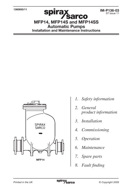
1360850/11<br />
<strong>MFP14</strong>, <strong>MFP14</strong>S <strong>and</strong> <strong>MFP14</strong>SS<br />
<strong>Automatic</strong> <strong>Pumps</strong><br />
Installation <strong>and</strong> Maintenance Instructions<br />
<strong>MFP14</strong><br />
IM-P136-03<br />
ST Issue 11<br />
1. Safety information<br />
2. General<br />
product information<br />
3. Installation<br />
4. Commissioning<br />
5. Operation<br />
6. Maintenance<br />
7. Spare parts<br />
8. Fault finding<br />
IM-P136-03 Printed in the ST UK Issue 11 © Copyright 2009 1
Safe operation of these products can only be guaranteed if they are properly installed,<br />
commissioned, used <strong>and</strong> maintained by qualified personnel (see Section 1.11) in<br />
compliance with the operating instructions. General installation <strong>and</strong> safety instructions<br />
for pipeline <strong>and</strong> plant construction, as well as the proper use of tools <strong>and</strong> safety<br />
equipment must also be complied with.<br />
1.1 Intended use<br />
Referring to the Installation <strong>and</strong> Maintenance Instructions, name-plate <strong>and</strong><br />
Technical Information Sheet, check that the product is suitable for the intended<br />
use / application. The products listed below fully comply with the requirements of<br />
the European Pressure Equipment Directive 97 / 23 / EC, ATEX Directive 94/ 9 / EC <strong>and</strong><br />
carry the <strong>and</strong> marks when so required. The products fall within the following<br />
Pressure Equipment Directive categories:<br />
Product<br />
Group 1 Group 2<br />
Gases Gases<br />
Group 1<br />
Liquids<br />
Group 2<br />
Liquids<br />
<strong>MFP14</strong> All sizes - 2 - SEP<br />
<strong>MFP14</strong>S All sizes - 2 - SEP<br />
<strong>MFP14</strong>SS All sizes - 2 - SEP<br />
2<br />
1. General safety information<br />
Product marking per ATEX Directive 94/ 9 / EC II 2G CT3.<br />
i) The products have been specifically designed for use on steam, air <strong>and</strong><br />
water / condensate which are in Group 2 of the above mentioned Pressure<br />
Equipment Directive. The products’ use on other fluids may be possible but,<br />
if this is contemplated, <strong>Spirax</strong> <strong>Sarco</strong> should be contacted to confirm the<br />
suitability of the product for the application being considered.<br />
ii) Check material suitability, pressure <strong>and</strong> temperature <strong>and</strong> their maximum <strong>and</strong><br />
minimum values. If the maximum operating limits of the product are lower than<br />
those of the system in which it is being fitted, or if malfunction of the product could<br />
result in a dangerous overpressure or overtemperature occurrence, ensure<br />
a safety device is included in the system to prevent such over-limit situations.<br />
iii) Determine the correct installation situation <strong>and</strong> direction of fluid flow.<br />
iv) <strong>Spirax</strong> <strong>Sarco</strong> products are not intended to withst<strong>and</strong> external stresses that may<br />
be induced by any system to which they are fitted. It is the responsibility of the<br />
installer to consider these stresses <strong>and</strong> take adequate precautions to minimise<br />
them.<br />
v) Remove protection covers from all connections <strong>and</strong> protective film from all nameplates,<br />
where appropriate, before installation on steam or other high temperature<br />
applications.<br />
IM-P136-03 ST Issue 11
1.2 Access<br />
Ensure safe access <strong>and</strong> if necessary a safe working platform (suitably guarded)<br />
before attempting to work on the product. Arrange suitable lifting gear if required.<br />
1.3 Lighting<br />
Ensure adequate lighting, particularly where detailed or intricate work is required.<br />
1.4 Hazardous liquids or gases in the pipeline<br />
Consider what is in the pipeline or what may have been in the pipeline at some<br />
previous time. Consider: flammable materials, substances hazardous to health,<br />
extremes of temperature.<br />
1.5 Hazardous environment around the product<br />
Consider: explosion risk areas, lack of oxygen (e.g. tanks, pits), dangerous gases,<br />
extremes of temperature, hot surfaces, fire hazard (e.g. during welding), excessive<br />
noise, moving machinery.<br />
1.6 The system<br />
Consider the effect on the complete system of the work proposed. Will any proposed<br />
action (e.g. closing isolation valves, electrical isolation) put any other part of the<br />
system or any personnel at risk?<br />
Dangers might include isolation of vents or protective devices or the rendering<br />
ineffective of controls or alarms. Ensure isolation valves are turned on <strong>and</strong> off in a<br />
gradual way to avoid system shocks.<br />
1.7 Pressure systems<br />
Ensure that any pressure is isolated <strong>and</strong> safely vented to atmospheric pressure.<br />
Consider double isolation (double block <strong>and</strong> bleed) <strong>and</strong> the locking or labelling of<br />
closed valves. Do not assume that the system has depressurised even when the<br />
pressure gauge indicates zero.<br />
1.8 Temperature<br />
Allow time for temperature to normalise after isolation to avoid danger of burns.<br />
1.9 Tools <strong>and</strong> consumables<br />
Before starting work ensure that you have suitable tools <strong>and</strong> /or consumables<br />
available. Use only genuine <strong>Spirax</strong> <strong>Sarco</strong> replacement parts.<br />
1.10 Protective clothing<br />
Consider whether you <strong>and</strong>/or others in the vicinity require any protective clothing<br />
to protect against the hazards of, for example, chemicals, high /low temperature,<br />
radiation, noise, falling objects, <strong>and</strong> dangers to eyes <strong>and</strong> face.<br />
IM-P136-03 ST Issue 11 3
1.11 Permits to work<br />
All work must be carried out or be supervised by a suitably competent person.<br />
Installation <strong>and</strong> operating personnel should be trained in the correct use of the<br />
product according to the Installation <strong>and</strong> Maintenance Instructions.<br />
Where a formal 'permit to work' system is in force it must be complied with. Where<br />
there is no such system, it is recommended that a responsible person should know<br />
what work is going on <strong>and</strong>, where necessary, arrange to have an assistant whose<br />
primary responsibility is safety.<br />
Post 'warning notices' if necessary.<br />
1.12 H<strong>and</strong>ling<br />
Manual h<strong>and</strong>ling of large <strong>and</strong>/or heavy products may present a risk of injury. Lifting,<br />
pushing, pulling, carrying or supporting a load by bodily force can cause injury<br />
particularly to the back. You are advised to assess the risks taking into account the<br />
task, the individual, the load <strong>and</strong> the working environment <strong>and</strong> use the appropriate<br />
h<strong>and</strong>ling method depending on the circumstances of the work being done.<br />
1.13 Residual hazards<br />
In normal use the external surface of the product may be very hot. If used at the<br />
maximum permitted operating conditions the surface temperature of these products<br />
may reach temperatures of 200°C (392°F).<br />
These products are not self-draining. Take due care when dismantling or removing<br />
the product from an installation (refer to 'Maintenance instructions').<br />
1.14 Freezing<br />
Provision must be made to protect products which are not self-draining against<br />
frost damage in environments where they may be exposed to temperatures below<br />
freezing point.<br />
1.15 Disposal<br />
Unless otherwise stated in the Installation <strong>and</strong> Maintenance Instructions, this<br />
product is recyclable <strong>and</strong> no ecological hazard is anticipated with its disposal<br />
providing due care is taken.<br />
1.16 Returning products<br />
Customers <strong>and</strong> stockists are reminded that under EC Health, Safety <strong>and</strong><br />
Environment Law, when returning products to <strong>Spirax</strong> <strong>Sarco</strong> they must provide<br />
information on any hazards <strong>and</strong> the precautions to be taken due to contamination<br />
residues or mechanical damage which may present a health, safety or<br />
environmental risk. This information must be provided in writing including<br />
Health <strong>and</strong> Safety data sheets relating to any substances identified as hazardous<br />
or potentially hazardous.<br />
4<br />
IM-P136-03 ST Issue 11
2. General product information<br />
2.1 General description<br />
The <strong>Spirax</strong> <strong>Sarco</strong> MFP series of automatic pumps are simply displacement receivers operated by<br />
steam or compressed air. They are generally used to lift liquids such as condensate to a higher<br />
level. Subject to the conditions being suitable, the pump can also be used to directly drain closed<br />
vessels under vacuum or pressure. In conjunction with a float steam trap, the pump is used to<br />
effectively drain temperature controlled heat exchangers under all operating conditions.<br />
The <strong>Spirax</strong> <strong>Sarco</strong> MFP automatic pump range is available as follows:<br />
<strong>MFP14</strong> SG iron body <strong>and</strong> cover<br />
<strong>MFP14</strong>S Cast steel body <strong>and</strong> cover<br />
<strong>MFP14</strong>SS Stainless steel body <strong>and</strong> cover<br />
St<strong>and</strong>ards<br />
These products fully comply with the requirements of the European Pressure Equipment<br />
Directive 97 / 23 / EC, ATEX Directive 94 / 9 / EC <strong>and</strong> carry the <strong>and</strong> marks when so required.<br />
Certification<br />
<strong>MFP14</strong> - This product is available with certification to EN 10204 3.1.<br />
<strong>MFP14</strong>S <strong>and</strong> <strong>MFP14</strong>SS - These products are available with certification to EN 10204 3.1 <strong>and</strong><br />
designed in a accordance with ASME VIII Div 1.<br />
Note: All certification /inspection requirements must be stated at the time of order placement.<br />
Note: For further information see Technical Information Sheet TI-P136-02.<br />
2.2 Sizes <strong>and</strong> pipe connections<br />
1", 1½", 2" <strong>and</strong> 3" x 2" screwed BSP (BS 21 parallel).<br />
<strong>MFP14</strong> DN25, DN40, DN50 <strong>and</strong> DN80 x DN50;<br />
flanged EN 1092 PN16, ANSI B 16.5 Class 150 <strong>and</strong> JIS/KS B 2238 10.<br />
2" <strong>and</strong> 3" x 2" screwed BSP/NPT is available to special order.<br />
DN50;<br />
<strong>MFP14</strong>S flanged EN 1092 PN16, ANSI B 16.5 Class 150 <strong>and</strong> JIS/KS B 2238 10.<br />
The ½" motive fluid inlet <strong>and</strong> 1" exhaust connections can be supplied with<br />
screwed BSP/NPT or SW connections.<br />
2" screwed BSP (NPT connections are available to special order).<br />
DN50;<br />
<strong>MFP14</strong>SS flanged EN 1092 PN16, ANSI B 16.5 Class 150 <strong>and</strong> JIS/KS B 2238 10.<br />
The ½" motive fluid inlet <strong>and</strong> 1" exhaust connections can be supplied with<br />
screwed BSP/NPT or SW connections.<br />
IM-P136-03 ST Issue 11 5
2.3 Pressure / temperature limits<br />
(ADM/ASME Pressure vessel codes Version 5.0)<br />
Body design conditions PN16<br />
Maximum motive inlet pressure <strong>MFP14</strong> <strong>and</strong> <strong>MFP14</strong>S 13.8 bar g (PN16)<br />
(steam air or gas) <strong>MFP14</strong>SS 10.96 bar g (PN16)<br />
<strong>MFP14</strong> 16 bar g @ 120°C<br />
PMA Maximum allowable pressure <strong>MFP14</strong>S 16 bar g @ 120°C<br />
<strong>MFP14</strong>SS 16 bar g @ 93°C<br />
<strong>MFP14</strong> 300°C @ 12.8 bar g<br />
TMA Maximum allowable temperature <strong>MFP14</strong>S 300°C @ 10.8 bar g<br />
<strong>MFP14</strong>SS 300°C @ 9.3 bar g<br />
Minimum allowable temperature. For lower temperatures consult <strong>Spirax</strong> <strong>Sarco</strong> 0°C<br />
<strong>MFP14</strong> 13.8 bar g @ 198°C<br />
PMO Maximum operating pressure <strong>MFP14</strong>S 13.8 bar g @ 198°C<br />
<strong>MFP14</strong>SS 10.96 bar g @ 188°C<br />
<strong>MFP14</strong> 198°C @ 13.8 bar g<br />
TMO Maximum operating temperature <strong>MFP14</strong>S 198°C @ 13.8 bar g<br />
<strong>MFP14</strong>SS 188°C @ 10.96 bar g<br />
Minimum operating temperature. For lower temperatures consult <strong>Spirax</strong> <strong>Sarco</strong> 0°C<br />
Total lift or backpressure (static head plus pressure in the return system) which must be<br />
below the motive fluid inlet pressure to allow capacity to be achieved:-<br />
Height (H) in metres x 0.0981 plus pressure (bar g) in return line, plus downstream piping friction<br />
pressure drop in bar calculated at a flowrate of the lesser of six times the actual condensate<br />
rate or 30 000 litres/h.<br />
Recommended filling head above the pump 0.3 m<br />
Minimum filling head required 0.15 m (reduced capacity)<br />
St<strong>and</strong>ard pump operates with liquids of specific gravity: 1 down to 0.8<br />
DN40 <strong>and</strong> DN25 DN50 DN80 x DN50<br />
Pump discharge per cycle 7 litres 12.8 litres 19.3 litres<br />
Steam consumption 16 kg/h maximum 20 kg/h maximum 20 kg/h maximum<br />
Air consumption (Free air) 4.4 dm3 /s maximum 5.6 dm3 /s maximum 5.6 dm3 /s maximum<br />
Temperature limits<br />
(Ambient )<br />
-10°C to 200°C -10°C to 200°C -10°C to 200°C<br />
6<br />
IM-P136-03 ST Issue 11
<strong>MFP14</strong><br />
<strong>MFP14</strong>S<br />
<strong>MFP14</strong>SS<br />
Temperature °C<br />
Temperature °C<br />
Temperature °C<br />
���<br />
���<br />
���<br />
���<br />
���<br />
��<br />
�<br />
�<br />
The product must not be used in this region.<br />
For use in this region contact <strong>Spirax</strong> <strong>Sarco</strong> - As st<strong>and</strong>ard this product should not be<br />
used in this region or beyond its operating range.<br />
A - D Flanged PN16<br />
B - D Flanged JIS/KS 10<br />
C - D Flanged ANSI 150<br />
Steam<br />
saturation<br />
curve<br />
D<br />
� � � � �� �� ���� ��<br />
Pressure bar g<br />
���<br />
���<br />
���<br />
���<br />
B<br />
A C<br />
���<br />
��<br />
�<br />
� �<br />
Steam<br />
saturation<br />
curve<br />
� � � �� ��<br />
D<br />
���� ��<br />
Pressure bar g<br />
���<br />
���<br />
���<br />
���<br />
B C<br />
A<br />
���<br />
��<br />
�<br />
� �<br />
Steam<br />
saturation<br />
curve<br />
� � �<br />
D<br />
����� �� �� ��<br />
Pressure bar g<br />
IM-P136-03 ST Issue 11 7<br />
B<br />
C<br />
A
2.4 Materials<br />
No. Part Material<br />
<strong>MFP14</strong> SG iron (EN JS 1025) EN-GTS-400-18-LT<br />
1 Cover <strong>MFP14</strong>S Cast steel DIN GSC 25N/ASTM A216 WCB<br />
<strong>MFP14</strong>SS Cast<br />
stainless steel<br />
BS EN 10213-4/ASTM A351 CF3M<br />
2 Cover gasket Synthetic fibre<br />
3 Cover screws Stainless steel ISO 3506 Gr. A2-70<br />
<strong>MFP14</strong> SG iron (EN JS 1025) EN-GTS-400-18-LT<br />
4 Body <strong>MFP14</strong>S Cast steel DIN GSC 25N/ASTM A216 WCB<br />
<strong>MFP14</strong>SS Cast<br />
stainless steel<br />
1998 - 1.4409/ASTM A351 CF3M<br />
5 Pillar<br />
<strong>MFP14</strong><br />
<strong>MFP14</strong>S<br />
Stainless steel BS 970, 431 S29<br />
<strong>MFP14</strong>SS Stainless steel BS 970, 303 S31<br />
6 Connector rod Stainless steel BS 1449, 304 S11<br />
7 Float <strong>and</strong> lever Stainless steel AISI 304<br />
<strong>MFP14</strong> SG iron (EN JS 1025) EN-GTS-400-18-LT<br />
8 Eyebolt (integral) <strong>MFP14</strong>S Cast steel DIN GSC 25N/ASTM A216 WCB<br />
<strong>MFP14</strong>SS Cast<br />
stainless steel<br />
1998 - 1.4409/ASTM A351 CF3M<br />
9 Mechanism lever Stainless steel BS 3146 pt. 2 ANC 2<br />
10 Spring Inconel 718 ASTM 5962 / ASTM B367<br />
11<br />
Pressure plug<br />
<strong>MFP14</strong><br />
<strong>MFP14</strong>S<br />
Steel<br />
Steel<br />
DIN 267 Part III Class 5.8<br />
DIN 267 Part III Class 5.8<br />
Drain plug <strong>MFP14</strong>SS Stainless steel ASTM A182 - F316<br />
12/12a Check valves Stainless steel<br />
Screwed boss flanges <strong>MFP14</strong> Steel<br />
13<br />
Connecting flanges<br />
<strong>MFP14</strong>S Steel<br />
<strong>MFP14</strong>SS Stainless steel<br />
DIN PN16/ANSI 150<br />
ASTM A182 - F316L<br />
14 Mechanism bracket Stainless steel BS 3146 pt. 2 ANC 4B<br />
15 Bracket screws Stainless steel BS 6105 Gr. A2-70<br />
16 Inlet valve seat Stainless steel BS 970, 431 S29<br />
17 Inlet valve stem Stainless steel ASTM A276 440 B<br />
18 Inlet valve seat gasket Stainless steel BS 1449 409 S19<br />
19 Exhaust valve seat Stainless steel BS 970 431 S29<br />
20 Exhaust valve Stainless steel BS 3146 pt. 2 ANC 2<br />
21 Exhaust valve seat gasket Stainless steel BS 1449 409 S19<br />
22 EPM actuator ALNICO<br />
23 'O' ring seal EPDM<br />
* 24 Shaft Stainless steel BS 970 431 S29<br />
* 25 Socket set screw Stainless steel BS 6105 Grade A2<br />
* 26 Socket set screw Stainless steel BS 970 431 S29<br />
* 27 Locking nut Stainless steel Grade A2<br />
28 Spring anchor Stainless steel BS 970 431 S29<br />
* Note: For item 24, 25, 26 <strong>and</strong> 27 see Figure 8, page 18<br />
8<br />
IM-P136-03 ST Issue 11
Exhaust outlet Operating pressure inlet<br />
19<br />
15<br />
21<br />
20<br />
23<br />
4<br />
22<br />
5<br />
6<br />
12<br />
Fig. 1 DN80 x DN50 <strong>MFP14</strong> shown<br />
3<br />
8<br />
IM-P136-03 ST Issue 11 9<br />
11<br />
1<br />
12a<br />
16<br />
18<br />
17<br />
14<br />
2<br />
28<br />
10<br />
7<br />
9<br />
13
2.6 Dimensions/weights (approximate)<br />
Metric (mm/kg)<br />
<strong>MFP14</strong><br />
Size A B C D E F G H J K L Weights<br />
JIS<br />
Pump Including<br />
*<br />
KS<br />
PN ANSI<br />
check valves<br />
only<br />
<strong>and</strong> flanges<br />
DN25 410 - 305 507 - 68 68 480 13 18 165 Ø280 51 58<br />
DN40 440 - 305 527 - 81 81 480 13 18 165 Ø280 54 63<br />
DN50 557 637.5 420 642 - 104 104 580 33 18 245 Ø321 72 82<br />
DN80 x DN50 573 637.5 420 642 430 119 104 580 33 18 245 342 88 98<br />
Imperial (ins/lbs)<br />
<strong>MFP14</strong><br />
Size A B C * D E F G H J K L Weights<br />
JIS<br />
KS<br />
PN ANSI<br />
Including<br />
Pump<br />
check valves<br />
only<br />
<strong>and</strong> flanges<br />
1" 16.1 - 12.0 19.9 - 2.7 2.7 18.9 0.5 0.7 6.5 Ø11.0 112.4 127.8<br />
1½" 16.1 - 12.0 20.7 - 3.2 3.2 18.9 0.5 0.7 6.5 Ø11.0 119.0 138.9<br />
2" 21.9 25.0 16.5 25.3 - 4.1 4.1 22.8 1.3 0.7 9.6 Ø12.6 158.7 180.8<br />
3" x 2" 22.6 25.0 16.5 25.3 16.9 4.7 4.1 22.8 1.3 0.7 9.6 13.6 160.9 189.6<br />
* Please note: Dimension D only applies to the DN80 x DN50 pump which has an oval body.<br />
The DN25, DN40 <strong>and</strong> DN50 are round bodied therefore dimension L is sufficient.<br />
10<br />
IM-P136-03 ST Issue 11
1" BSP, NPT or SW exhaust<br />
Fig. 2 DN80 x DN50 <strong>MFP14</strong> shown<br />
H<br />
½" BSP, NPT or SW steam,<br />
compressed air or gas inlet<br />
* Please note: Dimension D only applies to the DN80 x DN50 pump which has an oval body.<br />
The DN25, DN40 <strong>and</strong> DN50 are round bodied therefore dimension L is sufficient.<br />
G Withdrawal<br />
distance<br />
C<br />
E<br />
Connecting<br />
flange<br />
L<br />
Integral lifting eye<br />
15 mm diameter<br />
B<br />
A<br />
IM-P136-03 ST Issue 11 11<br />
K<br />
Connecting<br />
flange<br />
F<br />
J<br />
D*
Vent to<br />
atmosphere.<br />
Flash steam, air<br />
<strong>and</strong> pump exhaust<br />
At least 305 mm (12")<br />
seal on overflow<br />
(if fitted)<br />
Fig. 3<br />
12<br />
3. Installation<br />
Pump exhaust<br />
Operating steam<br />
or gas supply<br />
Receiver Condensate<br />
Filling<br />
head<br />
MFP<br />
automatic<br />
pump<br />
*<br />
12 12a<br />
FT steam<br />
trap when<br />
steam is used<br />
Condensate return line<br />
H<br />
Height<br />
3.1 Installation - vented systems<br />
Caution. Before installation or any maintenance is performed, ensure that all steam, air<br />
or gas lines are isolated to prevent personnel injury.<br />
Ensure any residual internal pressure in the pump or connecting lines is carefully<br />
relieved. Also ensure any hot parts have cooled to prevent risk of injury from burns.<br />
Always wear appropriate safety clothing before carrying out any installation or<br />
maintenance work.<br />
An integral lifting eye is fitted to the pump to assist lifting. On no account should this be<br />
used to lift anything more than the pump. Always use suitable lifting gear <strong>and</strong> ensure the<br />
pump is safely secured.<br />
Note: If pumping a potentially explosive media, the motive supply media must be an<br />
inert gas with no oxygen present.<br />
1. Install the pump below the equipment to be drained with the exhaust connection vertically<br />
upwards. Pump should be installed with the recommended filling head (the vertical distance<br />
between the top of the pump <strong>and</strong> the bottom of the reservoir/receiver), see Section 3.2<br />
<strong>and</strong> Fig. 3. For other filling head variations, refer to separate capacity chart.<br />
2. To prevent equipment flooding during the pump discharge stroke, a vented receiver or<br />
reservoir pipe should be installed in a horizontal plane ahead of the pump as shown in<br />
Fig. 3. For proper receiver/reservoir sizing, refer to Tables 1 <strong>and</strong> 2 on page 13. All inlet<br />
line fittings must be full bore.<br />
3. Connect the check valves (12) <strong>and</strong> (12a) to the pump making sure that the flow through<br />
the valves is in the correct direction.<br />
For best performance, horizontal piping runs immediately ahead of the inlet check valve<br />
<strong>and</strong> after the discharge check valve should be kept to a minimum. Connect the discharge to<br />
the return main or other return point.<br />
Torque tighten inlet <strong>and</strong> outlet flange bolts to 76 - 84 N m (56 - 62 lbf ft).<br />
4. Connect the operating medium (steam, air or gas) supply to the motive supply inlet in the<br />
cover (see Fig. 2, page 11). Supply main should have a strainer <strong>and</strong> a steam trap (steam<br />
service) installed upstream of the supply inlet. The steam trap discharge should be piped<br />
to the receiver or reservoir piping ahead of the pump.<br />
* Recommended maximum motive/backpressure differential is between 2 - 4 bar g.<br />
5. The pump exhaust line must be piped unreduced <strong>and</strong> unrestricted to atmosphere. The line<br />
should be vertical, if possible. If horizontal runs must be used, line should be pitched so<br />
that it is self-draining to the pump or reciever. Refer to Table 3 for the recommended<br />
vent pipe sizing, page 14.<br />
IM-P136-03 ST Issue 11
3.2 Filling head / installation head<br />
There is often confusion between filling head <strong>and</strong> installation head. Care must be taken when<br />
calculating them. Filling head is measured from the top of the pump cover to the bottom of the<br />
receiver, installation head is measured from the bottom of the receiver to the ground.<br />
Recommended<br />
Filling head<br />
300 mm (12")<br />
Minimum 150 mm (6") with reduced capacity<br />
Installation head Maximum 1 m (39")<br />
Note: To achieve the rated capacity, the pump must be installed with the check valves as<br />
supplied by <strong>Spirax</strong> <strong>Sarco</strong>.<br />
Table 1 Inlet receiver capacities<br />
Sufficient reservoir volume is needed above the filling head level to accept the condensate<br />
reaching pump during the discharge stroke. The receiver can be a length of pipe of large<br />
diameter or a tank. If desired, receiver overflow piping can be installed as shown in Fig. 3 <strong>and</strong><br />
piped to a suitable drain. The piping must form a U-type water seal at least 305 mm (12")<br />
deep immediately after the receiver.<br />
Pump size<br />
Metric<br />
Receiver size<br />
Imperial<br />
DN25 0.60 m x DN200 24" x 8"<br />
DN40 0.60 m x DN200 24" x 8"<br />
DN50 0.65 m x DN250 26" x 10"<br />
DN80 x DN50 1.10 m x DN250 44" x 10"<br />
Table 2 Inlet piping with no receiver fitted<br />
When draining a single piece of equipment <strong>and</strong> a receiver is not supplied ahead of the pump,<br />
install with sufficient piping as given in the table below, <strong>and</strong> use the recommended filling head.<br />
This will prevent any flooding of the equipment while the pump is discharging. Note: The Table<br />
below illustrates the length of reservoir piping above the top of the pump when the pump is<br />
installed without a receiver.<br />
Metric<br />
Pump sizes DN25, DN40, DN50, DN80 x DN50<br />
Liquid Inlet check valve <strong>and</strong> pipe size<br />
load DN25 DN40 DN50 DN80 x 50<br />
kg/h m m m m<br />
277 or less 1.2 - - -<br />
454 2.0 1.2 - -<br />
681 3.0 1.5 1.2 -<br />
908 4.0 1.8 1.5 -<br />
1 362 - 3.0 2.1 -<br />
1 816 - 3.6 3.0 -<br />
2 270 - - 3.6 1.2<br />
2 724 - - - 1.5<br />
3 178 - - - 1.8<br />
3 632 - - - 2.1<br />
4 086 - - - 2.4<br />
4 540 - - - 2.7<br />
9 994 - - - 3.0<br />
Imperial<br />
Pump sizes 1", 1½", 2", 3" x 2"<br />
Liquid Inlet check valve <strong>and</strong> pipe size<br />
load 1" 1½" 2" 3" x 2"<br />
lb/h ft ft ft ft<br />
598 or less 3.9 - - -<br />
546 6.6 3.9 - -<br />
1 500 9.8 4.9 4 -<br />
2 000 13.1 5.9 5 -<br />
3 000 - 9.8 7 -<br />
4 000 - 11.8 10 -<br />
5 000 - - 12 4<br />
6 000 - - - 5<br />
7 000 - - - 6<br />
8 000 - - - 7<br />
9 000 - - - 8<br />
10 000 - - - 9<br />
11 000 - - - 10<br />
IM-P136-03 ST Issue 11 13
Table 3 Receiver vent sizing<br />
The minimum vent diameter of the receiver should be as follows:<br />
Pump size Receiver vent diameter<br />
DN25 1" 50 mm (2")<br />
DN40 1½" 65 mm (2½")<br />
DN50 2" 80 mm (3")<br />
DN80 x DN50 3" x 2" 100 mm (4")<br />
3.3 Installation - closed loop steam systems<br />
Note: A closed-loop steam installation is one in which the exhaust line of the pump is piped<br />
back (pressure equalized) to the steam space being drained.<br />
Caution<br />
Before installation or any maintenance is performed, ensure that all steam, air or gas<br />
lines are isolated to prevent personnel injury.<br />
Ensure any residual internal pressure in the pump or connecting lines is carefully<br />
relieved. Also ensure any hot parts have cooled to prevent risk of injury from burns.<br />
Always wear appropriate safety clothing before carrying out any installation or<br />
maintenance work.<br />
An integral lifting eye is fitted to the pump to assist lifting (pump weighs 70 kg,<br />
154 lbs). On no account should this be used to lift anything more than the pump.<br />
Always use suitable lifting gear <strong>and</strong> ensure the pump is safely secured.<br />
Note: If pumping a potentially explosive media, the motive supply media must be an<br />
inert gas with no oxygen present.<br />
1. Install the pump below the equipment being drained with the exhaust connection vertically<br />
upwards. The pump should be installed with the recommended filling head (vertical distance<br />
between the top of the pump <strong>and</strong> the bottom of the reservoir/receiver), see Section 3.2 <strong>and</strong><br />
Figs. 4 <strong>and</strong> 5. For other filling head variants, refer to separate capacity chart.<br />
2. To prevent equipment flooding during the pump discharge stroke, a vented receiver or<br />
reservoir pipe should be installed in a horizontal plane ahead of the pump as shown in<br />
Fig. 4. For proper receiver/reservoir sizing refer to Tables 1 <strong>and</strong> 2 on page 13. All inlet<br />
fittings must be full bore.<br />
3. Connect the check valves (12) <strong>and</strong> (12a) to the pump, making sure that the flow through the<br />
valves is in the correct direction.<br />
For best performance, horizontal piping runs immediately ahead of the inlet check valve<br />
<strong>and</strong> after the discharge check valve should be kept to a minimum. Connect the discharge<br />
to the return main or other return point.<br />
Torque tighten inlet <strong>and</strong> outlet flange bolts to 76 - 84 N m (56 - 62 lbf ft).<br />
4. Connect the operating medium (steam only) supply to the motive supply inlet in the cover.<br />
Supply main should have a strainer <strong>and</strong> a steam trap installed upstream of the supply inlet.<br />
Steam trap discharge should be piped to receiver or reservoir piping ahead of the pump.<br />
Recommended maximum motive/backpressure differential is between 2 - 4 bar g.<br />
5. Exhaust line should be piped, unrestricted, to the reservoir. (In some specific cases it can<br />
be connected to the inlet pipe between the control valve <strong>and</strong> the equipment or directly into<br />
the top (inlet side) of the equipment). A thermostatic air vent should be installed at the<br />
highest point of the exhaust line to vent all non-condensibles during start-up. Any horizontal<br />
runs in the exhaust line should be pitched so that the line is self-draining.<br />
6. If, at any time, the backpressure against the pump is less than the pressure in the<br />
equipment being drained, a properly sized float <strong>and</strong> thermostatic trap must be installed<br />
between the pump <strong>and</strong> discharge check valve as shown in Fig. 5.<br />
14<br />
IM-P136-03 ST Issue 11
Temperature<br />
control<br />
P1<br />
Fig. 4<br />
Draining L.P. heat exchanger to<br />
overhead return. Pressure at pump<br />
outlet P2 exceeds pressure of<br />
supply to heat exchanger P1.<br />
Temperature<br />
control<br />
P1<br />
Air vent<br />
Heat exchanger<br />
Reservoir<br />
Filling head<br />
Air vent<br />
Heat exchanger<br />
MFP<br />
automatic<br />
pump<br />
Reservoir<br />
Filling head<br />
½" HP<br />
steam supply<br />
Strainer<br />
IFT steam trap<br />
P2<br />
12<br />
FT steam trap.<br />
Fitted before<br />
downstream<br />
check valve<br />
12a<br />
Return<br />
line<br />
Fig. 5<br />
Draining heat exchanger to overhead return. Pressure<br />
at pump outlet P2 does not always exceed pressure<br />
of supply to heat exchanger P1.<br />
MFP<br />
automatic<br />
pump<br />
Exhaust<br />
line<br />
12 12a<br />
½" HP<br />
steam supply<br />
Strainer<br />
Exhaust<br />
line<br />
IFT steam trap<br />
Return<br />
line<br />
IM-P136-03 ST Issue 11 15<br />
P2
16<br />
4. Commissioning<br />
1. Slowly open supply (steam, air or gas) to provide pressure at the MFP pump inlet valve.<br />
Check that trap is operational.<br />
2. Open isolation valves in the condensate inlet <strong>and</strong> discharge line.<br />
3. Open valve(s) ahead of the unit allowing condensate to enter the receiver <strong>and</strong> fill the pump<br />
body. Pump will discharge when full.<br />
4. Observe operation for any abnormalities. MFP pump(s) should cycle periodically (minimum<br />
cycle time is 8 seconds) with an audible exhaust at the end of the pumping cycle. If any<br />
irregularities are observed, recheck installation instructions for proper arrangement -<br />
also reference Section 8 - Fault finding. Consult <strong>Spirax</strong> <strong>Sarco</strong> if necessary.<br />
5. If overflow piping has been provided, check that a water seal has been established<br />
to prevent any steam from being emitted in normal operation. Prime piping if necessary.<br />
5. Operation<br />
1. Before start up the float (7) is at its lowest position with the steam valve (17) closed <strong>and</strong><br />
exhaust valve (20) open (Fig. 6).<br />
2. When liquid flows by gravity through inlet check valve (12) into the pump body, the float (7)<br />
will rise.<br />
3. As the float (7) continues to rise the mechanism link (9) is engaged which increases the<br />
tension in the springs (10). When the float (7) has risen to its upper tripping position, the<br />
linkage mechanism snaps upward over centre. The energy in the springs is released as<br />
mechanism link (9) accelerates upward, simultaneously opening the motive steam inlet<br />
valve <strong>and</strong> closing the exhaust valve (Fig. 7).<br />
4. Steam flow through the inlet valve (17) increases the pressure within the body. This closes<br />
the inlet check valve (12) <strong>and</strong> forces out the liquid through the discharge check valve (12a).<br />
5. As the liquid level in the pump body falls the float lowers <strong>and</strong> the mechanism link (9) is<br />
engaged, which again increases the tension in the springs (10). When the float reaches<br />
the lower tripping position, the linkage mechanism snaps downward over centre. The<br />
energy in the spring is released thus accelerating the mechanism downward simultaneously<br />
opening the exhaust valve <strong>and</strong> closing the steam inlet valve.<br />
6. When the pressure in the pump body has exhausted to the same level as the pressure in<br />
the inlet pipe, the inlet check valve opens. Liquid will again flow through the check valve<br />
to fill the body <strong>and</strong> begin the next cycle.<br />
IM-P136-03 ST Issue 11
Condensate<br />
in<br />
Exhaust outlet open<br />
20<br />
10<br />
12<br />
Inlet<br />
check<br />
valve<br />
Fig. 6 Filling stroke<br />
Motive<br />
steam inlet<br />
closed<br />
17<br />
9<br />
Exhaust outlet closed<br />
IM-P136-03 ST Issue 11 17<br />
7<br />
12a<br />
Outlet<br />
check<br />
valve<br />
Fig. 7 Discharge stroke<br />
Condensate out<br />
Motive<br />
steam inlet<br />
open
Mechanism inspection <strong>and</strong> repair<br />
Caution. Before installation or any<br />
maintenance is performed, ensure that all<br />
steam, air or gas lines are isolated to<br />
prevent personnel injury.<br />
Consider what media or substance may<br />
have been or be within the pump <strong>and</strong><br />
ascertain what possible hazards or injury<br />
may be caused by opening the pump.<br />
Ensure any residual internal pressure in<br />
the pump or connecting lines is carefully<br />
relieved. Also ensure any hot parts have<br />
cooled to prevent risk of injury from burns.<br />
Always wear appropriate safety clothing<br />
before carrying out any installation or<br />
maintenance work.<br />
An integral lifting eye is fitted to the pump to<br />
assist lifting. On no account should this be<br />
used to lift anything more than the pump.<br />
Always use suitable lifting gear <strong>and</strong><br />
ensure the pump is safely secured.<br />
When dismantling the pump, care should<br />
be taken to prevent personal injury from<br />
the strong snap action mechanism.<br />
Always h<strong>and</strong>le with care.<br />
1. Disconnect all connections to the cover. Remove cover bolts <strong>and</strong> lift the cover <strong>and</strong><br />
mechanism assembly from the body, noting the cover orientation.<br />
2. Visually inspect the mechanism to verify that it is free of dirt <strong>and</strong> scale <strong>and</strong> moves freely.<br />
Note: The socket set screws (Fig. 8 items 25, 26) are factory set <strong>and</strong> must not be<br />
disturbed during the following maintenance procedures.<br />
3. Visually check springs (item 10, Fig. 9). If defective, remove nuts <strong>and</strong> washers <strong>and</strong> slide<br />
spring assemblies from shafts. Replace with new spring assemblies (see Step 5e -<br />
spring setting) <strong>and</strong> install new nuts <strong>and</strong> washers, using Loctite 620 adhesive on threads<br />
of shaft.<br />
4. To check inlet <strong>and</strong> exhaust valves:a.<br />
Remove shaft (item 24, Fig. 8) from mechanism end of connector rod <strong>and</strong> rotate float <strong>and</strong><br />
connector rod to opposite side of pillar.<br />
b. Remove spring split pins/washers <strong>and</strong> nuts <strong>and</strong> slide spring assemblies from pivot<br />
shafts.<br />
c. Remove locking nut from inlet valve stem. Note: this has been secured using loctite 620<br />
adhesive.<br />
d. Remove mechanism bracket screws <strong>and</strong> lift mechanism from cover.<br />
e. To remove exhaust valve (if necessary), ease exhaust side bracket off main shaft <strong>and</strong><br />
exhaust valve (This is achieved by lifting the levers up, away from the bracket feet, <strong>and</strong><br />
tilting the bracket sideways <strong>and</strong> up). Remove exhaust valve from lever.<br />
f. Remove seats (<strong>and</strong> inlet valve) from cover. Note their respective positions in the<br />
cover. The DN25 <strong>and</strong> DN40 valve seats can be identified by a double row of diamond<br />
grooves on the exhaust seat <strong>and</strong> a single row on the inlet seat. The DN50 <strong>and</strong><br />
DN50 x DN80 valve seats can be distinguished as the inlet valve seat contains a<br />
series of holes around each flat, whilst the exhaust valve seat is blank.<br />
g. Visually inspect seating surfaces of inlet <strong>and</strong> exhaust valves for signs of wear (inlet<br />
valve must be removed to check seat). Clean seating areas <strong>and</strong> re-install or replace<br />
if necessary.<br />
18<br />
6. Maintenance<br />
25<br />
27<br />
24<br />
Fig. 8<br />
26<br />
27<br />
IM-P136-03 ST Issue 11
Fig. 9<br />
5. To reassemble, reverse the above procedure noting the following:a.<br />
Ensure exhaust <strong>and</strong> inlet seats (with inlet valve) are placed in correct locations<br />
(Step 4f) <strong>and</strong> tighten torque to 129 - 143 N m (95 - 105 lbf ft).<br />
b. Exhaust valve assembly - Place spring into body of exhaust valve. Slide valve on to lever<br />
whilst holding spring down in bottom of bore. Fit socket set screw <strong>and</strong> lock-nut to valve.<br />
c. Torque tighten mechanism retaining screws to 38 - 42 N m (28 - 31 lbf ft).<br />
d. Replace split pin on inlet valve.<br />
e. Reset exhaust valves as follows - With the valve operating lever against the stop<br />
closest to the cover (i.e. exhaust valve in the closed position) <strong>and</strong> the valve held firmly<br />
on its seat, screw in the set screw until it touches the drive pin <strong>and</strong> then unscrew it<br />
3¾ turns for the DN80 x DN50 <strong>and</strong> DN50 pumps <strong>and</strong> 2¾ turns for the DN40 <strong>and</strong> DN25<br />
pumps. Lock this screw in this position.<br />
6. Float replacement - Unscrew the float from the retaining bolt. It will be necessary to<br />
remove the float lever shaft to gain access to the hex socket. Reassemble the new float<br />
to the lever using a new bolt, washers <strong>and</strong> Loctite 620 adhesive on the bolt threads. If<br />
the lever shaft has been removed, fit new split pins <strong>and</strong> washers.<br />
7. When reinstalling the cover <strong>and</strong> mechanism assembly, the cover should be oriented as<br />
noted (Step 1) above. Always fit new gaskets. Torque tighten cover bolts to 121-134 N m<br />
(89 - 99 lbf ft). Follow the start-up procedure (Section 4, Commisioning) to bring the<br />
pump back into operation.<br />
IM-P136-03 ST Issue 11 19<br />
10<br />
10
20<br />
7. Spare parts<br />
The spare parts available are detailed below. No other parts are available as spares.<br />
Available spares<br />
Cover gasket 2<br />
Float 7<br />
Inlet/outlet check valve (each) 12<br />
Cover <strong>and</strong> internal mechanism<br />
assembly (complete) 1, 2, 7<br />
Valve set 16, 17,<br />
(inlet <strong>and</strong> exhaust valve 18, 19,<br />
<strong>and</strong> seats) 20, 21<br />
Spring <strong>and</strong> shaft kit 10<br />
Mechanism kit<br />
(including inlet <strong>and</strong> exhaust valves<br />
<strong>and</strong> securing screws)<br />
Fig. 10 <strong>MFP14</strong> shown<br />
12<br />
19<br />
21<br />
20<br />
16<br />
18<br />
17<br />
17 (hidden)<br />
10<br />
IM-P136-03 ST Issue 11<br />
1<br />
2<br />
7<br />
12
8. Fault finding<br />
If a correctly sized MFP automatic pump does not operate properly, when fitted to a new<br />
installation, an incorrect arrangement can be suspected. For existing installations where the<br />
pump operates occasionally or not at all, the cause is often a change in the system supply or<br />
backpressure conditions beyond the original design parameters. With the system conditions<br />
<strong>and</strong> problem symptoms determined, check the following in turn <strong>and</strong> correct as necessary.<br />
Caution:<br />
Installation <strong>and</strong> troubleshooting should be performed by qualified personnel. Before<br />
disconnecting any connections to the pump or piping system, every effort should be made<br />
to assure that internal pressure has been relieved <strong>and</strong> that the motive supply line is isolated<br />
to prevent inadvertent discharge of the pump. Consider what media or substance may<br />
have been or be within the pump <strong>and</strong> ascertain what possible hazards or injury may be<br />
caused by opening the pump. When disconnecting any connection, piping /bolts should<br />
be removed slowly so that if the line is under pressure, this fact will be apparent before<br />
completely removing the pipe or component.<br />
Warning:<br />
Always relieve pressure before disconnecting any joint.<br />
SYMPTOM 1 Pump fails to operate on start-up.<br />
Cause 1a Motive supply closed.<br />
Check <strong>and</strong> cure 1a Open valves to supply motive pressure to pump.<br />
Cause 1b Condensate inlet line closed.<br />
Check <strong>and</strong> cure 1b Open all valves to allow condensate to reach pump.<br />
Cause 1c Condensate discharge line closed.<br />
Check <strong>and</strong> cure 1c Open all valves to allow free discharge from pump to destination.<br />
Cause 1d Motive pressure insufficient to overcome backpressure.<br />
Check <strong>and</strong> cure 1d Check motive pressure <strong>and</strong> static backpressure. Adjust motive<br />
pressure to 0.6 to 1 bar (8.7 to 14.5 psi) or more higher than static<br />
backpressure. It is strongly recommended that the maximum<br />
differential pressure is not more than 2 - 4 bar g.<br />
Cause 1e Check that the valve(s) are not installed in the wrong direction.<br />
Check <strong>and</strong> cure 1e Verify proper flow direction <strong>and</strong> correct if required.<br />
Cause 1f Restricted vent.<br />
Check <strong>and</strong> cure 1f On vented or closed systems, ensure that the vent line is unrestricted<br />
<strong>and</strong> self-draining to the pump or receiver.<br />
Continued overleaf<br />
IM-P136-03 ST Issue 11 21
SYMPTOM 2 Supply line/equipment flooded, but pump appears to cycle<br />
normally (periodic audible exhaust observed).<br />
Cause 2a Pump undersized.<br />
Check <strong>and</strong> cure 2a Verify rated capacity table (TI-P136-02). Increase check valve size or<br />
install additional pump as required.<br />
Cause 2b Insufficient filling head.<br />
Check <strong>and</strong> cure 2b Verify required filling head per Section 3, page 12 - Lower pump<br />
to achieve required filling head.<br />
Cause 2c Insufficient motive pressure to achieve rated capacity.<br />
Check <strong>and</strong> cure 2c Check motive pressure setting <strong>and</strong> maximum backpressure during<br />
operation. Compare to capacity table (TI-P136-02). Increase motive<br />
pressure as required to meet load conditions. It is strongly recommended<br />
that the maximum differential pressure is not more than 2 - 4 bar g.<br />
Cause 2d Restriction in condensate inlet line.<br />
Check <strong>and</strong> cure 2d Verify that full bore fittings are used. Clean the strainer, if fitted. Check<br />
that all valves are fully open.<br />
Cause 2e Inlet or outlet check valve stuck open (debris).<br />
Check <strong>and</strong> cure 2e Isolate check valve <strong>and</strong> relieve line pressure. Remove disc check<br />
valve <strong>and</strong> visually inspect the disc <strong>and</strong> spring. Ensure these are free<br />
from debris clean seating surfaces to reinstall or replace if necessary.<br />
SYMPTOM 3 Supply line /equipment flooded, <strong>and</strong> pump has stopped cycling<br />
(audible periodic exhaust not observed).<br />
Cause 3a Discharge line closed or blocked.<br />
Check <strong>and</strong> cure 3a Check motive pressure <strong>and</strong> static backpressure (at pump discharge).<br />
If equal, a closed or blocked discharge line is suspected. Check all<br />
valves downstream of pump to ensure an unobstructed discharge.<br />
Cause 3b Discharge check valve stuck closed.<br />
Check <strong>and</strong> cure 3b After checking per 3(a), isolate discharge check valve <strong>and</strong> relieve line<br />
pressure. Remove the check valve <strong>and</strong> visually inspect. Clean seating<br />
surfaces <strong>and</strong> reinstall or replace, if necessary.<br />
Cause 3c Insufficient motive pressure.<br />
Check <strong>and</strong> cure 3c If motive pressure is below static backpressure, increase motive<br />
pressure setting to 0.6 to 1 bar (8.7 to 14.5 psi) or more above the static<br />
backpressure.<br />
Do not exceed rated pressure limits of equipment. It is strongly<br />
recommended that the maximum differential pressure is not more<br />
than 2 - 4 bar g.<br />
For Steps 3(d) to 3(g) - with exhaust /feedback line isolated from the equipment being drained<br />
(close-loop systems), break the exhaust/feedback connection at the pump cover <strong>and</strong>:-<br />
Important safety note:<br />
For steps (d) through to (g). It is necessary to disconnect the exhaust/feedback line at the<br />
pump exhaust connection. To avoid injury to personnel on closed loop systems care should be<br />
exercised to ensure that the pump is isolated (motive supply, condensate inlet <strong>and</strong> discharge<br />
22<br />
IM-P136-03 ST Issue 11
<strong>and</strong> exhaust feedback line all closed) <strong>and</strong> that internal pressure is relieved prior to breaking<br />
this connection. Also, under fault conditions it is possible that hot condensate may run out of<br />
the exhaust connection when disconnected for both closed loop <strong>and</strong> vented systems. This<br />
possibility should be taken into consideration when performing these Steps to avoid scalding<br />
personnel. Always wear suitable protective safety clothing/equipment. When dismantling the<br />
pump, care should be taken to prevent personal injury from the strong snap action mechanism.<br />
Always h<strong>and</strong>le with care.<br />
Cause 3d Motive inlet valve leaking/or worn.<br />
Check <strong>and</strong> cure 3d Slowly open the motive supply line, leaving the condensate inlet <strong>and</strong><br />
discharge lines closed. Observe the exhaust connection for significant<br />
steam or air leakage. If leakage is observed <strong>and</strong> is not considered to be<br />
flash steam, an inlet valve problem is indicated. Isolate pump, remove<br />
cover <strong>and</strong> mechanism assembly <strong>and</strong> visually inspect. Replace inlet<br />
valve <strong>and</strong> seat assembly.<br />
Cause 3e Mechanism faults:-<br />
1. Broken springs/shaft<br />
2. Ruptured float<br />
3. Mechanism binding<br />
Check <strong>and</strong> cure 3e With motive line open, slowly open the condensate inlet line to the pump<br />
allowing pump to fill <strong>and</strong> observe exhaust connection. Keep personnel<br />
clear of exhaust! If condensate is emitted from the exhaust connection<br />
without the pump mechanism tripping a mechanism fault is clearly<br />
indicated.<br />
Isolate the pump by shutting off motive supply <strong>and</strong> condensate inlet,<br />
remove cover <strong>and</strong> mechanism assembly, <strong>and</strong> visually inspect. Examine<br />
springs/mechanism <strong>and</strong> float for obvious defects. Manually operate the<br />
mechanism <strong>and</strong> check for any source of binding or increased friction.<br />
Repair <strong>and</strong>/or replace all defective parts observed.<br />
Cause 3f Exhaust/feedback causing vapour lock (vented or closed loop).<br />
Check <strong>and</strong> cure 3f If the mechanism is heard to trip <strong>and</strong> no fluid is emitted from the exhaust<br />
connection, slowly open the discharge line from the pump <strong>and</strong> observe<br />
operation. Keep personnel clear of exhaust connection. If pump cycles<br />
normally, a fault in the exhaust/feedback line is suspected. Recheck<br />
the exhaust /feedback piping layout for compliance with the installation<br />
instructions. Exhaust /feedback line must be self-draining to prevent<br />
vapour locking the pump.<br />
Fit thermostatic air vent to balance line on closed loop applications.<br />
Ensuring it is higher than the possible flood level of the equipment it<br />
is draining.<br />
Cause 3g Inlet check valve stuck closed.<br />
Check <strong>and</strong> cure 3g If the mechanism does not trip <strong>and</strong> fluid does not emit it is suspected<br />
that the fault lies in the condensate inlet piping. Ensure that all valves<br />
leading to the pump have been opened. If so, this indicates that the inlet<br />
check valve is stuck closed or there is insufficient filling head. Isolate<br />
the pump <strong>and</strong> check valve <strong>and</strong> relieve line pressure:<br />
- Remove the check valve <strong>and</strong> visually inspect.<br />
- Clean seating surfaces <strong>and</strong> reinstall or replace, if necessary.<br />
- Reinstall exhaust/feedback connection <strong>and</strong> open line.<br />
Symptom 3 continued overleaf.<br />
IM-P136-03 ST Issue 11 23
SYMPTOM 3 Supply line/equipment flooded, <strong>and</strong> pump has stopped cycling<br />
CONTD. (audible periodic exhaust not observed).<br />
Cause 3h Inlet strainer blocked.<br />
Check <strong>and</strong> cure 3h Close isolation valve ahead of strainer. Remove strainer cap <strong>and</strong><br />
screen. Clean screen or replace if damaged. Insert screen in cap <strong>and</strong><br />
refit to strainer. Open isolation valve.<br />
SYMPTOM 4 Clanging or banging in return main after discharges.<br />
Cause 4a Vacuum created at pump outlet after discharge because of<br />
acceleration/deceleration of large water slug in return main<br />
(usually results from long horizontal run with multiple rises <strong>and</strong><br />
drops).<br />
Check <strong>and</strong> cure 4a Install a vacuum breaker at the top of the lift (at highest point in return<br />
line). For pressurised return systems an air eliminator may be required<br />
downstream of the vacuum breaker. Consult <strong>Spirax</strong> <strong>Sarco</strong>.<br />
Cause 4b Pump 'blow-by'.<br />
Check <strong>and</strong> cure 4b Check condensate inlet pressure <strong>and</strong> static backpressure at the<br />
pump discharge. If the inlet pressure equals or exceeds the static<br />
backpressure, a 'blow through' problem is suspected. On vented<br />
systems, check for leaking traps discharging into the condensate inlet<br />
line which would increase inlet line pressure. Replace any faulty traps.<br />
On closed loop systems, if condensate inlet pressure can exceed<br />
static backpressure under normal operation (i.e. boost in equipment<br />
operating pressure via a modulating control valve or significant decrease<br />
in static return main pressure), a pump/trap combination is required.<br />
The pump/trap combination will prevent passage of steam into the<br />
return main <strong>and</strong> allow the pump to cycle normally when condensate is<br />
present (See Fig. 5, page 15).<br />
Cause 4c Differential pressure too high. If the steam motive pressure vastly<br />
exceeds the required pressure to overcome the backpressure<br />
acting against the pump, the temperature of the pumped<br />
condensate will be at a greatly elevated temperature to the<br />
condensate in the return line. The flash steam caused by the<br />
higher temperature pumped condensate will collapse when it<br />
comes into contact with the cooler condensate in the return line,<br />
causing an audible banging.<br />
Check <strong>and</strong> cure 4c It is strongly recommended that the steam motive supply pressure does<br />
not exceed the total possible backpressure by more than 2 - 4 bar g.<br />
A motive supply taken from higher pressure steam lines should be<br />
reduced by a suitable pressure reducing valve.<br />
24<br />
IM-P136-03 ST Issue 11
SYMPTOM 5 Vent line discharging excessive flash steam<br />
(vented applications only).<br />
Cause 5a Faulty steam traps discharging live steam into condensate inlet<br />
line (see also 4(b), Pump 'blow-by').<br />
Check <strong>and</strong> cure 5a Check for leaking traps discharging into condensate return. Repair or<br />
replace faulty traps.<br />
Cause 5b Excessive (over 20 kg /h or 45 lb /h) flash steam being vented<br />
through pump.<br />
Check <strong>and</strong> cure 5b Vent receiver or reservoir piping ahead of pump.<br />
Cause 5c Exhaust valve stuck or worn.<br />
Check <strong>and</strong> cure 5c Isolate pump <strong>and</strong> remove cover <strong>and</strong> mechanism assembly. Remove<br />
exhaust valve <strong>and</strong> seat assembly. Visually inspect seating surface<br />
Clean <strong>and</strong> reinstall or replace, if worn.<br />
IM-P136-03 ST Issue 11 25
26<br />
IM-P136-03 ST Issue 11
IM-P136-03 ST Issue 11 27
28<br />
IM-P136-03 ST Issue 11


