SV60 and SV60H Safety Valves - Spirax Sarco
SV60 and SV60H Safety Valves - Spirax Sarco
SV60 and SV60H Safety Valves - Spirax Sarco
You also want an ePaper? Increase the reach of your titles
YUMPU automatically turns print PDFs into web optimized ePapers that Google loves.
3170050/11<br />
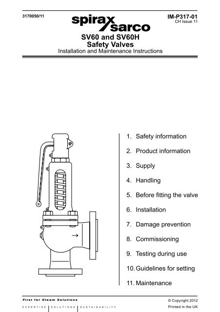
<strong>SV60</strong> <strong>and</strong> <strong>SV60</strong>H<br />
<strong>Safety</strong> <strong>Valves</strong><br />
Installation <strong>and</strong> Maintenance Instructions<br />
1. <strong>Safety</strong> information<br />
2. Product information<br />
3. Supply<br />
4. H<strong>and</strong>ling<br />
5. Before fitting the valve<br />
6. Installation<br />
7. Damage prevention<br />
8. Commissioning<br />
9. Testing during use<br />
10. Guidelines for setting<br />
11. Maintenance<br />
IM-P317-01<br />
CH Issue 11<br />
© Copyright 2012<br />
IM-P317-01 CH Issue 11 1<br />
Printed in the UK
2<br />
1. <strong>Safety</strong> information<br />
Safe operation of the unit can only be guaranteed if it is properly installed, commissioned<br />
<strong>and</strong> maintained by a qualified person (see Section 1.11) in compliance with the<br />
operating instructions. General installation <strong>and</strong> safety instructions for pipeline <strong>and</strong><br />
plant construction, as well as the proper use of tools <strong>and</strong> safety equipment must also<br />
be complied with.<br />
1.1 Intended use<br />
Referring to these Installation <strong>and</strong> Maintenance Instructions, Name-plate<br />
<strong>and</strong> Technical Information Sheet, check that the product is suitable for the intended<br />
use/application. The <strong>SV60</strong> safety valve range complies with the requirements of the<br />
European Pressure Equipment Directive 97/23/EC <strong>and</strong> carry the mark. They fall<br />
within Category 4 for Group 2 Gases.<br />
i) The product has been specifically designed for use on steam, air, inert industrial<br />
gases <strong>and</strong> liquids which are in Group 2 of the above mentioned Pressure Equipment<br />
Directive. The product’s use on other fluids may be possible but, if this is<br />
contemplated, <strong>Spirax</strong> <strong>Sarco</strong> should be contacted to confirm the suitability of<br />
the product for the application being considered.<br />
ii) Check material suitability, pressure <strong>and</strong> temperature <strong>and</strong> their maximum <strong>and</strong><br />
minimum values. If the maximum operating limits of the product are lower than<br />
those of the system in which it is being fitted, or if malfunction of the product<br />
could result in a dangerous overpressure or overtemperature occurance, ensure<br />
a safety device is included in the system to prevent such over-limit situations.<br />
iii) Determine the correct installation situation <strong>and</strong> direction of fluid flow.<br />
iv) <strong>Spirax</strong> <strong>Sarco</strong> products are not intended to withst<strong>and</strong> external stresses that<br />
may be induced by any system to which they are fitted. It is the responsibility<br />
of the installer to consider these stresses <strong>and</strong> take adequate precautions to<br />
minimise them.<br />
v) Remove protective covers from all connections <strong>and</strong> protective film from all nameplates,<br />
where appropriate, before installation on steam or other high temperature<br />
applications.<br />
1.2 Access<br />
Ensure safe access <strong>and</strong> if necessary a safe working platform (suitably guarded)<br />
before attempting to work on the product. Arrange suitable lifting gear if required.<br />
1.3 Lighting<br />
Ensure adequate lighting, particularly where detailed or intricate work is required.<br />
1.4 Hazardous liquids or gases in the pipeline<br />
Consider what is in the pipeline or what may have been in the pipeline at some<br />
previous time. Consider; flammable materials, substances hazardous to health,<br />
extremes of temperature.<br />
1.5 Hazardous environment around the product<br />
Consider; explosion risk areas, lack of oxygen (e.g. tanks, pits), dangerous gases,<br />
extremes of temperature, hot surfaces, fire hazard (e.g. during welding), excessive<br />
noise, moving machinery.<br />
IM-P317-01 CH Issue 11
1.6 The system<br />
Consider the effect on the complete system of the work proposed. Will any proposed<br />
action (e.g. closing isolation valves, electrical isolation) put any other part of the<br />
system or any personnel at risk?<br />
Dangers might include isolation of vents or protective devices or the rendering<br />
ineffective of controls or alarms. Ensure isolation valves are turned on <strong>and</strong> off in a<br />
gradual way to avoid system shocks.<br />
1.7 Pressure systems<br />
Ensure that any pressure is isolated <strong>and</strong> safely vented to atmospheric pressure.<br />
Consider double isolation (double block <strong>and</strong> bleed) <strong>and</strong> the locking or labelling of<br />
closed valves. Do not assume that the system has depressurised even when the<br />
pressure gauge indicates zero.<br />
1.8 Temperature<br />
Allow time for temperature to normalise after isolation to avoid danger of burns.<br />
1.9 Tools <strong>and</strong> consumables<br />
Before starting work ensure that you have suitable tools <strong>and</strong>/or consumables<br />
available. Use only genuine <strong>Spirax</strong> <strong>Sarco</strong> replacement parts.<br />
1.10 Protective clothing<br />
Consider whether any protective clothing is required by yourself <strong>and</strong>/or others<br />
in the vicinity to protect against the hazards of, for example, chemicals, high/low<br />
temperature, noise, falling objects, <strong>and</strong> dangers to eyes <strong>and</strong> face.<br />
1.11 Permits to work<br />
All work must be carried out or be supervised by a suitably competent person.<br />
Installation <strong>and</strong> operating personnel should be trained in the correct use of the<br />
product according to these instructions.<br />
Where a formal 'permit to work' system is in force it must be complied with. Where<br />
there is no such system, it is recommended that a responsible person should know<br />
what work is going on <strong>and</strong>, where necessary, arrange to have an assistant whose<br />
primary responsibility is safety.<br />
Post 'warning notices' if necessary.<br />
1.12 H<strong>and</strong>ling<br />
Where the weight of the product exceeds 20 kg it is recommended that suitable<br />
lifting equipment is used to prevent personal injury.<br />
1.13 Residual hazards<br />
In normal use the external surface of the product may be very hot. If used at the<br />
maximum permitted operating conditions the surface temperature of some<br />
products may reach temperatures in excess of 200°C.<br />
Many products are not self-draining. Take due care when dismantling or removing<br />
the product from an installation (refer to Section 11, 'Maintenance').<br />
IM-P317-01 CH Issue 11 3
1.14 Freezing<br />
Provision must be made to protect products which are not self-draining against<br />
frost damage if they are inoperative in environments where they may be exposed<br />
to temperatures below freezing point.<br />
1.15 <strong>Safety</strong> information - Product specific<br />
This product should not be dismantled without first releasing the compression on<br />
the control spring.<br />
This valve may contain a Viton component. If the valve has been subjected to a<br />
temperature approaching 315°C, the Viton material may have decomposed <strong>and</strong><br />
formed hydroflouric acid. Avoid skin contact <strong>and</strong> inhalation of any dust or fumes<br />
as this acid causes deep burns <strong>and</strong> damage to the respiratory system.<br />
1.16 Disposal<br />
Unless otherwise stated in the Installation <strong>and</strong> Maintenance Instructions, this<br />
product is recyclable <strong>and</strong> no ecological hazard is anticipated with its disposal<br />
providing due care is taken. However, if the valve is fitted with a Viton seat,<br />
special care must be taken to avoid potential health hazards associated with<br />
decomposition / burning of these seats.<br />
Viton:<br />
- Can be l<strong>and</strong>filled, when in compliance with National <strong>and</strong> Local regulations.<br />
- Can be incinerated, but a scrubber must be used to remove Hydrogen Fluoride,<br />
which is evolved from the product <strong>and</strong> with compliance to National <strong>and</strong> Local<br />
regulations.<br />
- Is insoluable in aquatic media.<br />
1.17 Returning products<br />
Customers <strong>and</strong> stockists are reminded that under UK <strong>and</strong> EC Health, <strong>Safety</strong> <strong>and</strong><br />
Environment Law, when returning products to <strong>Spirax</strong> <strong>Sarco</strong> they must provide<br />
information on any hazards <strong>and</strong> the precautions to be taken due to contamination<br />
residues or mechanical damage which may present a health, safety or environmental<br />
risk. This information must be provided in writing including Health <strong>and</strong> safety data<br />
sheets relating to any substances identified as hazardous.<br />
4<br />
IM-P317-01 CH Issue 11
Steam<br />
supply<br />
2. Product information<br />
Reducing<br />
valve<br />
To safe area<br />
Condensate<br />
<strong>Safety</strong><br />
valve<br />
Small bore<br />
drain<br />
Fig. 1 Typical installation of safety valve, downstream of pressure reducing valve station<br />
2.1 Description<br />
The <strong>SV60</strong> is a range of full lift flanged safety valves suitable for use on steam, inert industrial<br />
gas <strong>and</strong> water services.<br />
The <strong>SV60</strong> is suitable for the following applications; protection of steam boilers, pipelines <strong>and</strong><br />
pressure vessels, compressors <strong>and</strong> receivers <strong>and</strong> for most general process industry applications.<br />
The <strong>SV60</strong>H is suitable for use only on hot water boilers in accordance with DIN 4571.<br />
Available types<br />
There are two body material variations for these valves<br />
<strong>SV60</strong>7 <strong>and</strong> <strong>SV60</strong>7H SG iron<br />
<strong>SV60</strong>4 <strong>and</strong> <strong>SV60</strong>4H Carbon steel<br />
Inlet sizes range from DN20 to DN150<br />
The <strong>SV60</strong>7 <strong>and</strong> <strong>SV60</strong>4 are available with the option of easing lever <strong>and</strong> open or closed bonnets.<br />
The <strong>SV60</strong>7H <strong>and</strong> <strong>SV60</strong>4H have an easing lever <strong>and</strong> closed bonnet as st<strong>and</strong>ard. Open bonnet<br />
<strong>and</strong> sealed cap are not available for the 'H' version.<br />
St<strong>and</strong>ards <strong>and</strong> approvals<br />
All valves carry the mark <strong>and</strong> comply with the requirements of the European Pressure<br />
Equipment Directive 97/23/EC <strong>and</strong> fall within Category 4 for Group 2 gases.<br />
The <strong>SV60</strong>4 is approved by the TÜV to AD-Merkblatt A2, AD-Merkblatt A4, TRD 721, Vd TÜV 100<br />
<strong>and</strong> 100/4. Seat tightness to ASME/API st<strong>and</strong>ard 527-1992. Also Lloyds Register (LR) type<br />
approval, Certificate No. 01 / 00125 (E2).<br />
The <strong>SV60</strong>7H <strong>and</strong> <strong>SV60</strong>4H are approved by the TÜV to TRD 721 <strong>and</strong> Vd TÜV Merkblatt SV100<br />
<strong>and</strong> 100/4.<br />
Certification<br />
A manufacturers' Typical Test Report is provided as st<strong>and</strong>ard for each valve which will<br />
include the valve set <strong>and</strong> hydraulic test pressure. Also available on request is material<br />
certification in accordance with EN 10204 3.1.<br />
IM-P317-01 CH Issue 11 5
2.2 Sizes <strong>and</strong> end connections<br />
Inlet sizes include DN20, DN25, DN32, DN40, DN50, DN65, DN80, DN100, DN125 <strong>and</strong><br />
DN150.<br />
Valve type Inlet connection Outlet connection<br />
<strong>SV60</strong>7 <strong>and</strong> <strong>SV60</strong>7H<br />
PN16 (DN65 to DN150 only)<br />
PN25<br />
PN16<br />
PN16<br />
<strong>SV60</strong>4 <strong>and</strong> <strong>SV60</strong>4H PN40 PN16<br />
<strong>SV60</strong>4 ASME 300 ANSI 150<br />
St<strong>and</strong>ard PN flanges are to EN 1092 <strong>and</strong> ASME 300 to EN 1759-1.<br />
The body drain connection is ½" BSP.<br />
2.3 Pressure/temperature limits - <strong>SV60</strong>4 <strong>and</strong> <strong>SV60</strong>7<br />
<strong>SV60</strong>4<br />
PN40 inlet<br />
<strong>SV60</strong>7<br />
PN25 inlet<br />
<strong>SV60</strong>7<br />
PN16 inlet<br />
6<br />
(see page 8 for the <strong>SV60</strong>4H <strong>and</strong> <strong>SV60</strong>7H pressure / temperature limits)<br />
Temperature °C<br />
Temperature °C<br />
Temperature °C<br />
400<br />
300<br />
230<br />
200<br />
100<br />
-10<br />
0 10 20<br />
Pressure bar g<br />
30 40<br />
350<br />
300<br />
The product must not be used in this region.<br />
Steam<br />
saturation<br />
curve<br />
230<br />
200<br />
Steam<br />
100<br />
0<br />
saturation<br />
curve<br />
-10<br />
0 5 10 15 20 25<br />
Pressure bar g<br />
350<br />
300<br />
230<br />
200<br />
100<br />
0<br />
Steam<br />
saturation<br />
curve<br />
-10<br />
0<br />
4 8<br />
Pressure bar g<br />
12 16<br />
A tungsten alloy spring must be used in this region.<br />
Consult <strong>Spirax</strong> <strong>Sarco</strong> for further information.<br />
IM-P317-01 CH Issue 11
Body design conditions<br />
Set pressure maximum<br />
Set pressure minimum<br />
<strong>SV60</strong>4 PN40<br />
<strong>SV60</strong>7 PN16 or PN25<br />
Size Saturated Air Water<br />
steam<br />
DN20 x DN32 29 bar g 40 bar g 40 bar g<br />
DN25 x DN40 29 bar g 40 bar g 40 bar g<br />
DN32 x DN50 29 bar g 40 bar g 40 bar g<br />
DN40 x DN65 29 bar g 40 bar g 40 bar g<br />
<strong>SV60</strong>4 PN40 DN50 x DN80 29 bar g 40 bar g 40 bar g<br />
DN65 x DN100 29 bar g 32 bar g 32 bar g<br />
DN80 x DN125 29 bar g 32 bar g 32 bar g<br />
DN100 x DN150 25 bar g 25 bar g 25 bar g<br />
DN125 x DN200 20 bar g 20 bar g 20 bar g<br />
DN150 x DN250 16 bar g 16 bar g 16 bar g<br />
DN20 x DN32 22.5 bar g 25 bar g 25 bar g<br />
DN25 x DN40 22.5 bar g 25 bar g 25 bar g<br />
DN32 x DN50 22.5 bar g 25 bar g 25 bar g<br />
DN40 x DN65 22.5 bar g 25 bar g 25 bar g<br />
PN25 DN50 x DN80 22.5 bar g 25 bar g 25 bar g<br />
DN65 x DN100 22.5 bar g 25 bar g 25 bar g<br />
DN80 x DN125 22.5 bar g 25 bar g 25 bar g<br />
<strong>SV60</strong>7 DN100 x DN150 22.5 bar g 25 bar g 25 bar g<br />
DN125 x DN200 20 bar g 20 bar g 20 bar g<br />
DN150 x DN250 14.6 bar g 16 bar g 16 bar g<br />
DN65 x DN100 14.6 bar g 16 bar g 16 bar g<br />
DN80 x DN125 14.6 bar g 16 bar g 16 bar g<br />
PN16 DN100 x DN150 14.6 bar g 16 bar g 16 bar g<br />
DN125 x DN200 14.6 bar g 16 bar g 16 bar g<br />
DN150 x DN250 14.6 bar g 16 bar g 16 bar g<br />
<strong>SV60</strong>4 0.2 bar g<br />
<strong>SV60</strong>7 0.2 bar g<br />
<strong>SV60</strong>4 400°C<br />
Maximum<br />
Temperature <strong>SV60</strong>7 350°C<br />
Minimum -10°C<br />
Overpressure<br />
Steam <strong>and</strong> gas 5%<br />
Liquids 10%<br />
Performance data Blowdown limit Steam <strong>and</strong> gas 10%<br />
Liquids 20%<br />
Backpressure limit Up to 10% of set pressure<br />
Designed for a maximum <strong>SV60</strong>4 60 bar g<br />
inlet cold hydaulic test<br />
pressure of:<br />
<strong>SV60</strong>7<br />
PN25<br />
PN16<br />
38 bar g<br />
24 bar g<br />
IM-P317-01 CH Issue 11 7
2.4 Pressure/temperature limits - <strong>SV60</strong>4H <strong>and</strong> <strong>SV60</strong>7H<br />
(see pages 6 <strong>and</strong> 7 for the <strong>SV60</strong>4 <strong>and</strong> <strong>SV60</strong>7 pressure / temperature limits)<br />
Please contact <strong>Spirax</strong> <strong>Sarco</strong>, when so required, for relevant details regarding the maximum<br />
allowable limits that the shell can withst<strong>and</strong>.<br />
<strong>SV60</strong>4H<br />
120<br />
100<br />
A<br />
8<br />
Temperature°C<br />
The product must not be used in this region.<br />
A - B Flanged PN16.<br />
A - C Flanged PN25.<br />
A - D Flanged PN40.<br />
Body design conditions<br />
Set pressure range<br />
Temperature<br />
50<br />
0 0<br />
<strong>SV60</strong>7H<br />
120<br />
100<br />
A<br />
Temperature°C<br />
50<br />
Performance data<br />
Designed for a maximum inlet<br />
cold hydraulic test pressure of:<br />
0<br />
10 20<br />
Pressure bar g<br />
30 40<br />
0 5 10 15 16 20 25<br />
<strong>SV60</strong>4H PN40<br />
<strong>SV60</strong>7H PN16 or PN25<br />
Maximum 10 bar g<br />
Minimum 1 bar g<br />
EPDM seat<br />
Viton seat<br />
Pressure bar g<br />
Minimum 5°C<br />
Maximum 120°C<br />
Minimum 5°C<br />
Maximum 120°C<br />
Overpressure 10%<br />
Blowdown limit 10% of set pressure<br />
Derated coefficient of discharge values 0.5<br />
Backpressure limit Up to 10% of set pressure<br />
PN40 60 bar g<br />
PN25 38 bar g<br />
PN16 24 bar g<br />
D<br />
B C<br />
IM-P317-01 CH Issue 11
2.5 Dimensions/weights (approximate) in mm <strong>and</strong> kg<br />
Size Dimensions Weight<br />
Inlet / Outlet Flow Ø <strong>SV60</strong>4 <strong>SV60</strong>7<br />
A B C D <strong>SV60</strong>4H <strong>SV60</strong>7H<br />
DN20 - DN32 85 95 385 17.0 10.5 10.5<br />
DN25 - DN40 100 105 435 23.8 12.5 11.5<br />
DN32 - DN50 110 115 450 30.6 16.0 15.0<br />
DN40 - DN65 115 140 520 38.0 18.0 18.0<br />
DN50 - DN80 120 150 535 50.1 20.0 22.0<br />
DN65 - DN100 140 170 710 59.0 40.0 38.0<br />
DN80 - DN125 160 195 790 73.0 56.0 53.0<br />
DN100 - DN150 180 220 835 91.0 77.0 75.0<br />
DN125 - DN200 200 250 1 042 105.0 120.0 115.0<br />
DN150 - DN250 225 285 1 165 125.0 190.0 180.0<br />
Fig. 2<br />
D<br />
IM-P317-01 CH Issue 11 9<br />
A<br />
B<br />
C
2.6 Materials<br />
No. Part Material<br />
1 Body<br />
<strong>SV60</strong>4<br />
<strong>SV60</strong>7<br />
Carbon steel<br />
SG iron<br />
1.0619 + N<br />
GJS-400-18LT<br />
2 Seat<br />
DN20 -DN100<br />
DN125 -DN150<br />
Stainless steel<br />
Stainless steel<br />
1.4057<br />
ANC2<br />
3<br />
<strong>SV60</strong>4<br />
Bonnet<br />
<strong>SV60</strong>7<br />
Carbon steel<br />
SG iron<br />
1.0619 + N<br />
GJS-400-18LT<br />
4 Cap SG iron GJS-400-15<br />
5 Disc<br />
DN20 -DN100<br />
<strong>SV60</strong>4 <strong>and</strong> <strong>SV60</strong>7<br />
DN125 -DN150<br />
DN20 -DN125<br />
<strong>SV60</strong>4H <strong>and</strong> <strong>SV60</strong>7H<br />
DN150<br />
Stainless steel<br />
Stainless steel<br />
Stainless steel<br />
Stainless steel<br />
1.4021<br />
CA15<br />
1.4021<br />
CA15<br />
St<strong>and</strong>ard Chrome-vanadium alloy steel<br />
6 Spring For temperatures<br />
above 230°C<br />
Tungsten alloy steel<br />
7 Guide plate SG iron GJS-400-15<br />
8 Skirt<br />
DN20 -DN100<br />
DN125 -DN150<br />
Stainless steel<br />
Stainless steel<br />
1.4301<br />
1.4308<br />
9 Stem Stainless steel 1.4021<br />
10 Body bolts Steel CK35<br />
* 11 Spring plate Carbon steel C45E<br />
*<br />
12 Bearing ring DN80 - DN150 only Stainless steel 1.4021<br />
13 Spacer Stainless steel 1.4021<br />
14 Adjustment screw Stainless steel 1.4021<br />
15 Lock-nut Zinc plated carbon steel<br />
16 Cap bolt Zinc plated steel<br />
17 Collar Zinc plated carbon steel<br />
18 Lever SG iron GJS-400-15<br />
19 Lever pin Zinc plated carbon steel<br />
20 Circlip (not shown) Spring steel<br />
21 Stem pin Spring steel DIN 7343, A304<br />
22 Collets Stainless steel 1.4021<br />
23 Stem ball Stainless steel<br />
26 Collar pin Zinc plated carbon steel<br />
27 Collar circlip Spring stainless steel<br />
28 Packed lever spindle Stainless steel ASTM A276 431<br />
29 Lifting fork Carbon steel<br />
30 Gl<strong>and</strong> packing Graphite<br />
31 Gl<strong>and</strong> Stainless steel ASTM A276 304<br />
32 Gl<strong>and</strong> nut Carbon steel<br />
33 Guide plate gaskets (2 off) Reinforced exfoliated graphite<br />
34 Sealed cap gasket Universal SA<br />
35 Packed lever cap gasket Universal SA<br />
36 Body drain plug (½" BSP) Steel<br />
43 Bellows EPDM These parts<br />
44 Hose clamp Stainless steel are for the<br />
45 'O' ring EPDM/Viton <strong>SV60</strong>_H safety<br />
46 Nut Stainless steel valve only<br />
10<br />
IM-P317-01 CH Issue 11
32 31 30<br />
18<br />
35<br />
18<br />
22<br />
23<br />
36<br />
Packed easing<br />
lever<br />
29<br />
28<br />
<strong>SV60</strong>4H <strong>and</strong> <strong>SV60</strong>7H construction<br />
4<br />
44<br />
43<br />
45<br />
46<br />
17, 26, 27<br />
19, 20<br />
IM-P317-01 CH Issue 11 11<br />
4<br />
14<br />
15<br />
16<br />
Gas tight cap<br />
<strong>SV60</strong>4 <strong>and</strong> <strong>SV60</strong>7<br />
34<br />
6<br />
9<br />
3<br />
12 *<br />
11 *<br />
7<br />
10<br />
33<br />
13<br />
21<br />
5<br />
8<br />
2<br />
* Note: The spring plate (11) <strong>and</strong><br />
bearing ring design (12) varies<br />
according to the valve size <strong>and</strong><br />
set pressure. Please refer to<br />
IM-S13-35 for further details.<br />
1<br />
Fig. 3
2.7 How to select the <strong>SV60</strong> <strong>and</strong> <strong>SV60</strong>H safety valve:<br />
Model type <strong>SV60</strong><br />
4 = Carbon steel<br />
7 = SG iron<br />
Body material 4<br />
4H = Carbon steel<br />
7H = SG iron<br />
12<br />
A = Closed bonnet/easing lever<br />
* B = Closed bonnet/gas tight cap<br />
Configuration * C = Closed bonnet/packed easing lever A<br />
* D = Open bonnet/easing lever<br />
* Note: B, C <strong>and</strong> D apply to the <strong>SV60</strong>4 <strong>and</strong> <strong>SV60</strong>7 only<br />
S = Stainless steel with chrome-vanadium alloy<br />
steel spring (<strong>SV60</strong>4 <strong>and</strong> <strong>SV60</strong>7 only)<br />
T = Stainless steel with tungsten alloy<br />
Seal material steel spring (<strong>SV60</strong>4 <strong>and</strong> <strong>SV60</strong>7 only) S<br />
E = EPDM (<strong>SV60</strong>4H <strong>and</strong> <strong>SV60</strong>7H only)<br />
V = Viton (<strong>SV60</strong>4H <strong>and</strong> <strong>SV60</strong>7H only)<br />
Size DN20 to DN150 DN20<br />
Inlet connection<br />
PN16 (DN65 to DN150 only), PN25 or PN40<br />
ASME 300 (<strong>SV60</strong>4 only)<br />
PN40<br />
Selection example <strong>SV60</strong> 4 A S DN20 PN40<br />
How to order a new product<br />
Example: 1 off <strong>Spirax</strong> <strong>Sarco</strong> <strong>SV60</strong>4AS, DN20 flanged PN40 safety valve with a set pressure<br />
of 6 bar.<br />
IM-P317-01 CH Issue 11
3. Supply<br />
Normally, the valve will be supplied set at the required pressure <strong>and</strong> sealed.<br />
Setting of <strong>Spirax</strong> <strong>Sarco</strong> safety valves must only be carried out by authorised, competent persons.<br />
<strong>Spirax</strong> <strong>Sarco</strong> accepts no responsibility for valves which have been reset by unauthorised<br />
personnel.<br />
5. Before fitting the valve<br />
5.1 Ensure that the installation is correct (See example on Figure 1, page 5).<br />
5.2 Check that the details on the safety valve name-plate are compliant with the installation<br />
<strong>and</strong> process.<br />
5.3 Blow through the pipework to ensure that it is completely free of any foreign matter that may<br />
otherwise pass to the valve seat <strong>and</strong> cause damage, leading to seat leakage. Blowdown<br />
must be carried out before installing the safety valve.<br />
5.4 Ensure that valve is set to the correct pressure, see 'Testing during use', Section 9.<br />
5.5 Remove protective caps <strong>and</strong> seal.<br />
4. H<strong>and</strong>ling<br />
4.1 <strong>Valves</strong> should be transported in the upright position.<br />
4.2 Do not drop <strong>and</strong> avoid sudden shocks or heavy impacts.<br />
4.3 Always store in the suppliers packaging until required.<br />
4.4 Never carry a safety valve by the lifting lever.<br />
5.6 Remove any plastic securing straps from the lever.<br />
IM-P317-01 CH Issue 11 13
14<br />
6. Installation<br />
Note: Before actioning any installation observe the '<strong>Safety</strong> information' in Section 1.<br />
6.1 The valve should always be mounted vertically upwards with its main axis vertical.<br />
6.2 The valve should be fitted to the pipework or vessel by means of the shortest possible<br />
length of pipe or fitting.<br />
6.3 There should be no intervening valve or fitting i.e. it should not be possible to<br />
isolate the safety valve (see Figure 4).<br />
6.4 The inlet pipe connection should not be smaller than the valve (see Figures 7 <strong>and</strong> 8,<br />
page 16).<br />
6.5 The outlet pipe size should be equal or larger than the valve outlet to keep backpressure<br />
below 10% of the set pressure. Use long radius bends <strong>and</strong> fittings.<br />
6.6 Direct the outlet pipework to a safe point of discharge where there is no risk of injury<br />
to persons or damage to property in the event of the valve operating.<br />
6.7 The outlet pipework should be adequately supported such that it does not place undue<br />
stress on the safety valve.<br />
6.8 Where the outlet pipework is directed upwards (i.e. on steam service), a small bore<br />
drain should be provided at the lowest point (Figure 5). This drain should be taken to<br />
a place where any discharge will not create a hazard or inconvenience.<br />
6.9 For installation where condensate is likely to accumulate in the valve body, it is<br />
recommended that the ½" BSP body drain connection (Item 36, page 11) is piped to<br />
a safe drainage point.<br />
6.10 Each safety valve should have its own unrestricted discharge pipe.<br />
6.11 <strong>Safety</strong> valves with open bonnets may release fluid under pressure when discharging.<br />
Ensure this can be done safely.<br />
6.12 <strong>Safety</strong> valve lagging should be limited to the body only.<br />
6.13 <strong>Safety</strong> valves can operate very suddenly <strong>and</strong> will be too hot to touch without protection<br />
when installed on steam systems.<br />
IM-P317-01 CH Issue 11
Fig. 4<br />
Fig. 5<br />
Small bore<br />
drain to<br />
safe area<br />
�<br />
Discharge to<br />
safe area<br />
Small bore<br />
drain to<br />
safe area<br />
�<br />
IM-P317-01 CH Issue 11 15
16<br />
7. Damage prevention<br />
Excessive pressure loss at the inlet of a safety valve when it relieves will cause extremely<br />
rapid opening <strong>and</strong> closing of the valve, observed as chattering or hammering.<br />
This may result in reduced capacity as well as damage to seating faces <strong>and</strong> the other parts<br />
of the safety valve.<br />
When normal pressure is restored it is possible that the safety valve will leak.<br />
7.1 Solution<br />
Pressure loss at inlet should be no more than 3% of pressure differential between set<br />
pressure <strong>and</strong> superimposed backpressure when discharging.<br />
The safety valve should be fitted 8-10 pipe diameters downstream of converging, diverging<br />
fittings or bends (Figure 6).<br />
Inlet branches should be as Figures 7 <strong>and</strong> 8.<br />
Fig. 6<br />
8 - 10 Pipe diameters downstream<br />
of converging 'Y' fittings or bends<br />
r<br />
Radius 'r' not less<br />
than inlet diameter<br />
Fig. 7 Fig. 8<br />
Inlet area 'A'<br />
approximately twice<br />
that of inlet of area 'a'.<br />
a<br />
A<br />
IM-P317-01 CH Issue 11<br />
��<br />
��
8. Commissioning<br />
8.1 Once the safety valve has been fitted check that there are no leaks from either the<br />
inlet or the outlet connections.<br />
8.2 Test the valve by raising the system pressure. Check that the safety valve operates at<br />
the correct set pressure.<br />
8.3 Reduce the system pressure to the normal operating pressure <strong>and</strong> check that the<br />
safety valve reseats.<br />
9. Testing during use<br />
9.1 It is recommended that the safety valve be tested for correct operation on a regular<br />
basis as part of a documented <strong>and</strong> controlled procedure, the frequency of testing is<br />
dependant on the application <strong>and</strong> system conditions <strong>and</strong> an appropriate test interval<br />
must be decided by the user or relevant insurance company.<br />
Note: Use suitable protection against excess heat <strong>and</strong> noise when testing safety valves.<br />
9.2 Some valves are fitted with st<strong>and</strong>ard (open type) or packed easing levers to enable<br />
testing for correct operation during use.<br />
Do not operate the lever unless the system pressure is at least 85% of the safety valve<br />
set pressure.<br />
Do not use any tool or mechanical device (e.g. length of pipe) on the lever. Do not apply<br />
excessive force - H<strong>and</strong> operation only.<br />
IM-P317-01 CH Issue 11 17
10.1 Choice of set pressure<br />
A decision must be made regarding the pressure at which the safety valve should be set.<br />
The maximum set pressure, in accordance with BS 5500, is the safe working pressure of<br />
the plant it protects <strong>and</strong> the valve must achieve its rated capacity with an overpressure of<br />
no more than 10%.<br />
The <strong>SV60</strong> achieves its rated capacity at 5% over pressure (10% for the <strong>SV60</strong>H). If the valve<br />
is set too close to the operating pressure of the system the valve may operate prematurely.<br />
It will also fail to close satisfactorily when normal operating pressure is restored.<br />
Figure 9 outlines the way a safety valve operates.<br />
Fig. 9<br />
10.2 Setting the valve<br />
<strong>Spirax</strong> <strong>Sarco</strong> cannot be held responsible for unauthorised alteration of the set pressure.<br />
10.3 <strong>Valves</strong> supplied unset<br />
<strong>Valves</strong> supplied unset to approved agents will include a set pressure tag to be stamped with the<br />
appropriate set pressure in bar after setting.<br />
The tag should be permanently attached to the valve with locking wire <strong>and</strong> lead seal. The back<br />
of the blue instruction label affixed to each unset valve will indicate the pressure range of the<br />
spring fitted.<br />
18<br />
10. Guidelines for setting<br />
(By authorised <strong>and</strong> competent persons only)<br />
5% of set pressure<br />
Pressure<br />
Fig. 10<br />
Set<br />
pressure<br />
(Valve operates)<br />
Time<br />
Full lift position<br />
Re-seat differential<br />
Re-seat pressure<br />
(10% of set pressure)<br />
Flowrate = Maximum rating of pressure<br />
reducing valve<br />
A = 10% of safety valve set pressure,<br />
0.3 bar minimum<br />
B = Normal system pressure variation<br />
Note: The operating pressure of a<br />
system will vary <strong>and</strong> it is important that<br />
the safety valve is set high enough<br />
to accommodate such fluctuations.<br />
It can be seen that the safety valve does not<br />
re-seat when the pressure falls to the safety<br />
valve set pressure.<br />
There must be adequate differential between<br />
the maximum system operating pressure <strong>and</strong><br />
the safety valve set pressure if the valve is to<br />
re-seat.<br />
The maximum system operating pressure is<br />
most likely to occur during no-load conditions.<br />
Figure 10 shows the range within which the<br />
valve must be set.<br />
Maximum allowable<br />
working pressure<br />
or design pressure<br />
of vessel<br />
Maximum system<br />
operating pressure<br />
No-load condition<br />
Operating pressure<br />
A<br />
B<br />
Maximum setting of<br />
safety valve<br />
<strong>Safety</strong> valve may<br />
be set within<br />
this range<br />
Minimum setting of<br />
safety valve<br />
Re-seat differential<br />
IM-P317-01 CH Issue 11
11. Maintenance<br />
All safety valves should receive planned maintenance.<br />
Note: Before actioning any maintenance work please read '<strong>Safety</strong> information', Section 1.<br />
It is recommended that the <strong>Spirax</strong> <strong>Sarco</strong> <strong>SV60</strong> safety valves are returned to <strong>Spirax</strong> <strong>Sarco</strong>, or<br />
an approved <strong>Spirax</strong> <strong>Sarco</strong> agent, for a thorough overhaul periodically, please read 'Returning<br />
products', Section 1.17.<br />
The valve will be returned having been overhauled, tested re-set <strong>and</strong> sealed in accordance<br />
with industry st<strong>and</strong>ard procedures.<br />
IM-P317-01 CH Issue 11 19
20<br />
IM-P317-01 CH Issue 11


