

IN15, IN25M and IN40M Steam injectors - Spirax Sarco
IN15, IN25M and IN40M Steam injectors - Spirax Sarco
IN15, IN25M and IN40M Steam injectors - Spirax Sarco

You also want an ePaper? Increase the reach of your titles
YUMPU automatically turns print PDFs into web optimized ePapers that Google loves.
4014051/4<br />
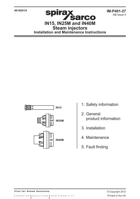
<strong>IN15</strong>, <strong>IN25M</strong> <strong>and</strong> <strong>IN40M</strong><br />
<strong>Steam</strong> <strong>injectors</strong><br />
Installation <strong>and</strong> Maintenance Instructions<br />
<strong>IN15</strong><br />
<strong>IN25M</strong><br />
<strong>IN40M</strong><br />
1. Safety information<br />
2. General<br />
product information<br />
3. Installation<br />
4. Maintenance<br />
5. Fault finding<br />
IM-P401-27<br />
AB Issue 4<br />
© Copyright 2012<br />
IM-P401-27 AB Issue 4 1<br />
Printed in the UK
2<br />
1. Safety information<br />
Pressure equipment not bearing the mark is classified 'Sound Engineering Practice'<br />
in accordance with Article 3, Paragraph 3 of the Pressure Equipment Directive<br />
97 / 23 / EC. It is the responsibility of the user to ensure that the product is installed <strong>and</strong><br />
operated safely. Safe operation of these products can only be guaranteed if they are<br />
properly installed, commissioned, used <strong>and</strong> maintained by qualified personnel (see<br />
Section 1.11) in compliance with the operating instructions. General installation <strong>and</strong><br />
safety instructions for pipeline <strong>and</strong> plant construction, as well as the proper use of tools<br />
<strong>and</strong> safety equipment must also be complied with. Detailed product information can be<br />
obtained from www.<strong>Spirax</strong><strong>Sarco</strong>.com or by contacting your local <strong>Spirax</strong> <strong>Sarco</strong> sales<br />
office.<br />
Note: By law, SEP products cannot be marked with the symbol.<br />
1.1 Intended use<br />
i) Check that the product is suitable for use with the intended fluid.<br />
ii) Check material suitability, pressure <strong>and</strong> temperature <strong>and</strong> their maximum <strong>and</strong> minimum<br />
values. If the maximum operating limits of the product are lower than those of the<br />
system in which it is being fitted, or if malfunction of the product could result in a<br />
dangerous overpressure or overtemperature occurrence, ensure a safety device is<br />
included in the system to prevent such over-limit situations.<br />
iii) Determine the correct installation situation <strong>and</strong> direction of fluid flow.<br />
iv) <strong>Spirax</strong> <strong>Sarco</strong> products are not intended to withst<strong>and</strong> external stresses that may be<br />
induced by any system to which they are fitted. It is the responsibility of the installer<br />
to consider these stresses <strong>and</strong> take adequate precautions to minimise them.<br />
v) Remove protection covers from all connections before installation.<br />
1.2 Access<br />
Ensure safe access <strong>and</strong> if necessary a safe working platform (suitably guarded) before<br />
attempting to work on the product. Arrange suitable lifting gear if required.<br />
1.3 Lighting<br />
Ensure adequate lighting, particularly where detailed or intricate work is required.<br />
1.4 Hazardous liquids or gases in the pipeline<br />
Consider what is in the pipeline or what may have been in the pipeline at some previous<br />
time. Consider: flammable materials, substances hazardous to health, extremes of<br />
temperature.<br />
1.5 Hazardous environment around the product<br />
Consider: explosion risk areas, lack of oxygen (e.g. tanks, pits), dangerous gases,<br />
extremes of temperature, hot surfaces, fire hazard (e.g. during welding), excessive noise,<br />
moving machinery.<br />
IM-P401-27 AB Issue 4
1.6 The system<br />
Consider the effect on the complete system of the work proposed. Will any proposed<br />
action (e.g. closing isolation valves, electrical isolation) put any other part of the system<br />
or any personnel at risk?<br />
Dangers might include isolation of vents or protective devices or the rendering ineffective<br />
of controls or alarms. Ensure isolation valves are turned on <strong>and</strong> off in a gradual way to<br />
avoid system shocks.<br />
1.7 Pressure systems<br />
Ensure that any pressure is isolated <strong>and</strong> safely vented to atmospheric pressure. Consider<br />
double isolation (double block <strong>and</strong> bleed) <strong>and</strong> the locking or labelling of closed valves.<br />
Do not assume that the system has depressurised even when the pressure gauge<br />
indicates zero.<br />
1.8 Temperature<br />
Allow time for temperature to normalise after isolation to avoid danger of burns.<br />
1.9 Tools <strong>and</strong> consumables<br />
Before starting work ensure that you have suitable tools <strong>and</strong> / or consumables available.<br />
Use only genuine <strong>Spirax</strong> <strong>Sarco</strong> replacement parts.<br />
1.10 Protective clothing<br />
Consider whether you <strong>and</strong>/or others in the vicinity require any protective clothing to<br />
protect against the hazards of, for example, chemicals, high/low temperature, radiation,<br />
noise, falling objects, <strong>and</strong> dangers to eyes <strong>and</strong> face.<br />
1.11 Permits to work<br />
All work must be carried out or be supervised by a suitably competent person.<br />
Installation <strong>and</strong> operating personnel should be trained in the correct use of the product<br />
according to the Installation <strong>and</strong> Maintenance Instructions.<br />
Where a formal 'permit to work' system is in force it must be complied with. Where<br />
there is no such system, it is recommended that a responsible person should know what<br />
work is going on <strong>and</strong>, where necessary, arrange to have an assistant whose primary<br />
responsibility is safety.<br />
Post 'warning notices' if necessary.<br />
1.12 H<strong>and</strong>ling<br />
Manual h<strong>and</strong>ling of large <strong>and</strong>/or heavy products may present a risk of injury. Lifting,<br />
pushing, pulling, carrying or supporting a load by bodily force can cause injury<br />
particularly to the back. You are advised to assess the risks taking into account the task,<br />
the individual, the load <strong>and</strong> the working environment <strong>and</strong> use the appropriate h<strong>and</strong>ling<br />
method depending on the circumstances of the work being done.<br />
1.13 Residual hazards<br />
In normal use the external surface of the product may be very hot.<br />
Many products are not self-draining. Take due care when dismantling or removing the<br />
product from an installation.<br />
IM-P401-27 AB Issue 4 3
1.14 Freezing<br />
Provision must be made to protect products which are not self-draining against<br />
frost damage in environments where they may be exposed to temperatures below<br />
freezing point.<br />
1.15 Safety information - Product specific<br />
<strong>Steam</strong> <strong>injectors</strong> operate at temperatures which could cause severe scalding, <strong>and</strong><br />
produce strong currents of very hot water. Do not touch or lean over open tanks which<br />
are being heated, even if the water still appears to be cold. Ensure closed tanks are<br />
adequately vented <strong>and</strong> that the vent is unobstructed. <strong>Steam</strong> supply pipework must be<br />
firmly anchored to prevent vibration <strong>and</strong> stress in the tank wall. Tanks must be adequately<br />
constructed <strong>and</strong> braced/stayed as necessary to avoid vibration. Consult your local<br />
<strong>Spirax</strong> <strong>Sarco</strong> engineer if in any doubt.<br />
1.16 Disposal<br />
This product is recyclable <strong>and</strong> no ecological hazard is anticipated with its disposal<br />
providing due care is taken.<br />
1.17 Returning products<br />
Customers <strong>and</strong> stockists are reminded that under EC Health, Safety <strong>and</strong> Environment<br />
Law, when returning products to <strong>Spirax</strong> <strong>Sarco</strong> they must provide information on any<br />
hazards <strong>and</strong> the precautions to be taken due to contamination residues or mechanical<br />
damage which may present a health, safety or environmental risk. This information must<br />
be provided in writing including Health <strong>and</strong> Safety data sheets relating to any substances<br />
identified as hazardous or potentially hazardous.<br />
4<br />
IM-P401-27 AB Issue 4
2. General product information<br />
2.1 Description<br />
<strong>Spirax</strong> <strong>Sarco</strong> steam <strong>injectors</strong> use steam to raise the temperature of water, generally in a tank.<br />
They can also be used to heat other liquids.<br />
They work by using a jet of steam to draw in water through radial ports, mix it, <strong>and</strong> distribute<br />
the heated water throughout the tank.<br />
The circulation induced by the injector ensures thorough mixing <strong>and</strong> an even temperature<br />
throughout the tank.<br />
2.2 Limiting conditions<br />
Body design rating PN25<br />
Maximum saturated steam condition 17 bar g @ 207°C<br />
Maximum recommended heated water temperature<br />
(tank / vessel vented to atmosphere)<br />
90°C<br />
Minimum operating pressure 0.5 bar g<br />
<strong>IN40M</strong><br />
(available screwed or butt weld)<br />
Fig. 1 <strong>Steam</strong> <strong>injectors</strong><br />
<strong>IN15</strong><br />
<strong>IN25M</strong><br />
(available screwed or butt weld)<br />
IM-P401-27 AB Issue 4 5
6<br />
3. Installation<br />
3.1 General<br />
<strong>IN25M</strong> (1") <strong>and</strong> <strong>IN40M</strong> (1½") are supplied in male thread (BSPT or NPT) or butt-weld form.<br />
They may be fitted to a tank wall connection or to pipework in the tank. It may be necessary<br />
to fit a reinforcing plate to the tank wall.<br />
The <strong>IN15</strong> has a 1" male thread for direct mounting to a tank wall <strong>and</strong> a ½" female thread for<br />
the steam supply pipework.<br />
Do not use a wrench on the round body of an injector - ribs on the injector body allow a<br />
spanner to be used for fitting.<br />
For higher capacities, two or more <strong>injectors</strong> may be fitted in parallel.<br />
Screwed coupling Ribs for spanner<br />
<strong>Steam</strong> supply pipework Injector<br />
Fig. 2 <strong>IN25M</strong> / <strong>IN40M</strong> - Typical screwed installation direct to pipework<br />
<strong>Steam</strong> supply pipework<br />
Internal surface of tank<br />
Screwed coupling<br />
Ribs for spanner<br />
Reinforcing plate<br />
Fig. 3 <strong>IN25M</strong> / <strong>IN40M</strong> - Screwed coupling through tank wall<br />
Injector<br />
IM-P401-27 AB Issue 4
Internal surface of tank<br />
Fig. 4 <strong>IN25M</strong> / <strong>IN40M</strong> - Typical butt welded installation through tank wall (on a st<strong>and</strong>pipe)<br />
1" female socket<br />
Ribs for spanner<br />
Weld<br />
<strong>Steam</strong> supply pipework Injector<br />
Internal surface of tank<br />
Reinforcing plate<br />
Ensure holes are clear<br />
of the end of the socket<br />
Fig. 5 <strong>IN15</strong> injector - Typical installation through tank wall<br />
Reinforcing plate<br />
<strong>Steam</strong> supply pipework Injector<br />
3.2 Pipeline sizing<br />
Use the same size pipe as the injector:-<br />
15 mm pipe for <strong>IN15</strong>, 25 mm pipe for <strong>IN25M</strong> <strong>and</strong> 40 mm pipe for <strong>IN40M</strong>.<br />
Pipe sizes for multiple injector installations are as follows:-<br />
No. of <strong>injectors</strong> Type Minimum pipe size<br />
2 <strong>IN15</strong> 20 mm<br />
2 <strong>IN40M</strong> 65 mm<br />
3 <strong>IN40M</strong> 80 mm<br />
IM-P401-27 AB Issue 4 7
3.3 Recommended layout<br />
Position the injector:<br />
- horizontally,<br />
- at low level,<br />
- on the vertical centre line of the tank, (single <strong>injectors</strong>), a minimum of 150 mm from the<br />
side of the tank.<br />
- At one end of the tank.<br />
The injector may be installed on a coupling through the tank wall, or on a short pipeline as<br />
close to the end of the tank as possible.<br />
Pipework may be run inside or outside the tank. We recommend the use of a suitable thread<br />
locking compound on all threaded connections.<br />
Discharge from the injector must be kept clear of any obstructions in the tank, e.g. pipework,<br />
stays, etc.<br />
The distance between the injector <strong>and</strong> the end of the tank (L) must be as great as possible<br />
for quietest operation. The following minimum dimensions apply:-<br />
<strong>Steam</strong> pressure at injector inlet <strong>IN15</strong> <strong>IN25M</strong> / <strong>IN40M</strong><br />
(bar g) minimum length (L) minimum length (L)<br />
0.5 - 7.0 250 mm 500 mm<br />
7.1 - 10.0 300 mm 750 mm<br />
10.1 - 14.0 350 mm 1 000 mm<br />
14.1 - 17.0 400 mm 1 250 mm<br />
A minimum depth of water must be allowed below the injector (H):-<br />
Injector type Minimum dimension<br />
<strong>IN15</strong> 100 mm<br />
<strong>IN25M</strong> 150 mm<br />
<strong>IN40M</strong> 200 mm<br />
Fig. 6<br />
8<br />
Minimum<br />
150 mm<br />
Dimension H<br />
Dimension L<br />
IM-P401-27 AB Issue 4
Multiple <strong>injectors</strong><br />
Position the <strong>injectors</strong> equally across the width (W) of the tank to ensure adequate mixing <strong>and</strong><br />
maximum circulation. Leave at least 150 mm between the <strong>injectors</strong> <strong>and</strong> the tank side, <strong>and</strong> at<br />
least 300 mm between <strong>injectors</strong>.<br />
Fig. 7 Two injector layout<br />
Fig. 8 Three injector layout<br />
Minimum 150 or W<br />
4<br />
Minimum 300 or W<br />
2<br />
Minimum 150 or W<br />
6<br />
Minimum 300 or W<br />
3<br />
IM-P401-27 AB Issue 4 9<br />
W<br />
W
3.4 Systems<br />
A typical system is shown in Figure 9. All system parts should be fitted in a horizontal pipeline<br />
situated above the top of the tank. We recommend the fitting of a stop valve <strong>and</strong> a Y-type<br />
strainer upstream of the control valve. Install the strainer on its side to prevent a water pocket<br />
forming. Install the sensor <strong>and</strong> sensor pocket approximately one third of the way up the tank,<br />
ideally above, or above <strong>and</strong> to one side of, the injector(s). For boiler feedtank applications,<br />
keep the sensor well away from the cold make-up, condensate return, <strong>and</strong> flash steam inlets.<br />
If used, install the dial thermometer near the sensor.<br />
Fig. 9<br />
10<br />
Stop<br />
valve<br />
Y-type<br />
strainer<br />
Control<br />
valve<br />
Vacuum<br />
breaker<br />
Dial<br />
thermometer<br />
Controller<br />
<strong>and</strong><br />
sensor<br />
Injector<br />
Pocket<br />
IM-P401-27 AB Issue 4
4. Maintenance<br />
No specific maintenance is required. Any temperature controller should be calibrated<br />
periodically. We recommend an annual inspection of the injector <strong>and</strong> the steam supply<br />
pipework. Check that the injector discharge holes are not obstructed <strong>and</strong> that any screw<br />
threads are tight. Check that the tank vent is clear. Clean any strainer in the injector system.<br />
5. Fault finding<br />
If correctly sized, controlled, <strong>and</strong> installed in a suitable tank, the steam injector(s) will operate<br />
quietly with minimum noise <strong>and</strong> vibration. Noisy operation on installation could be caused<br />
by inadequately braced pipework or loose connections.<br />
Excessive noise <strong>and</strong> / or vibration in service is extremely unusual, but could be caused<br />
by an injector becoming loose or detached, or by one or more of the injector outlet nozzles<br />
becoming blocked.<br />
Heavy vibration may occur if the tank temperature is allowed to exceed 90°C, as the steam<br />
will not condense fully.<br />
If severe vibration is experienced, do not continue to use the injector(s), or the tank may be<br />
damaged. Shut off the steam supply <strong>and</strong> investigate the fault immediately.<br />
IM-P401-27 AB Issue 4 11
12<br />
IM-P401-27 AB Issue 4


