Type 20 and Type 40 Sizing Direct Steam Injection ... - Spirax Sarco
Type 20 and Type 40 Sizing Direct Steam Injection ... - Spirax Sarco
Type 20 and Type 40 Sizing Direct Steam Injection ... - Spirax Sarco

You also want an ePaper? Increase the reach of your titles
YUMPU automatically turns print PDFs into web optimized ePapers that Google loves.
Cert. No. LRQ 0963008 <strong>Type</strong> <strong>20</strong> <strong>and</strong> <strong>Type</strong> <strong>40</strong><br />
ISO 9001<br />
<strong>Sizing</strong><br />
<strong>Direct</strong> <strong>Steam</strong> <strong>Injection</strong> Humidifiers<br />
Product selection<br />
The best diffusion of steam into the air flow is achieved by spreading the outlet nozzles of the lance(s) evenly within the duct, vertically<br />
<strong>and</strong> horizontally.<br />
This is achieved by following the example through the five steps below.<br />
Step 1 - The known data<br />
Duct size<br />
1 800 mm high<br />
<strong>and</strong> 1 800 mm wide<br />
<strong>Steam</strong> pressure 1.5 bar g<br />
Required maximum<br />
steam flowrate<br />
110 kg/h<br />
<strong>Spirax</strong> <strong>Sarco</strong> valve connection Screwed<br />
Valve actuation Electric<br />
Actuator voltage 24 Vac 50 / 60 Hz<br />
Control signal VMD<br />
Step 3 - Select the lance model<br />
Select the lance model from Table 2 to match the known duct width.<br />
Step 2 - Select the lance<br />
Select the recommended number of lances required from Table 1 to<br />
match the known duct height.<br />
Table 1<br />
Duct height in mm Number of lances<br />
up to 1 000 1<br />
1 000 - 1 700 2<br />
1 700 - 2 <strong>20</strong>0 3<br />
2 <strong>20</strong>0 - 2 600 4<br />
2 600 <strong>and</strong> above 5<br />
Number of recommended lances required = 3<br />
Duct width in mm Table 2<br />
Maximum 450 630 900 1 <strong>20</strong>0 1 470 1 780 2 080 2 380 2 690 3 000 3 300 3 610 3 950<br />
Minimum 280 450 630 900 1 <strong>20</strong>0 1 470 1 780 2 080 2 380 2 690 3 000 3 300 3 610<br />
Lance model 1 1.5 2 3 4 5 6 7 8 9 10 11 12<br />
Recommended lance model = 6<br />
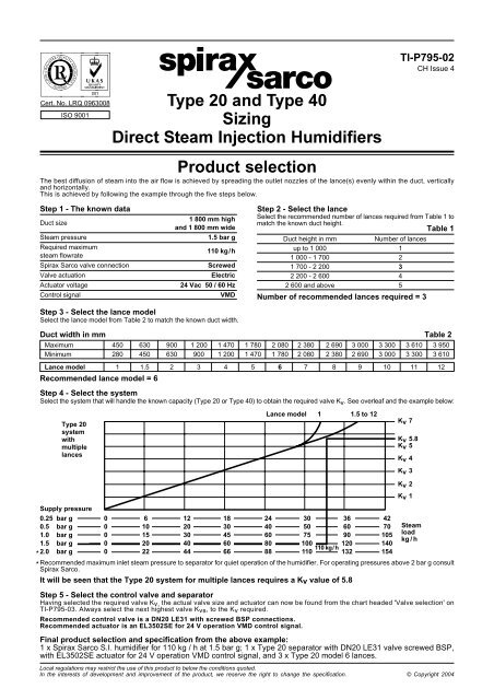
Step 4 - Select the system<br />
Select the system that will h<strong>and</strong>le the known capacity (<strong>Type</strong> <strong>20</strong> or <strong>Type</strong> <strong>40</strong>) to obtain the required valve Kv. See overleaf <strong>and</strong> the example below:<br />
<strong>Type</strong> <strong>20</strong><br />
system<br />
with<br />
multiple<br />
lances<br />
Lance model 1 1.5 to 12<br />
Supply pressure<br />
0.25 bar g 0 6 12 18 24 30 36 42<br />
0.5 bar g 0 10 <strong>20</strong> 30 <strong>40</strong> 50 60 70<br />
1.0 bar g 0 15 30 45 60 75 90 105<br />
1.5<br />
*<br />
2.0<br />
bar g<br />
bar g<br />
0<br />
0<br />
<strong>20</strong><br />
22<br />
<strong>40</strong><br />
44<br />
60<br />
66<br />
80<br />
88<br />
100 1<strong>20</strong><br />
110 kg / h<br />
110 132<br />
1<strong>40</strong><br />
154<br />
TI-P795-02<br />
CH Issue 4<br />
<strong>Steam</strong><br />
load<br />
kg / h<br />
* Recommended maximum inlet steam pressure to separator for quiet operation of the humidifier. For operating pressures above 2 bar g consult<br />
<strong>Spirax</strong> <strong>Sarco</strong>.<br />
It will be seen that the <strong>Type</strong> <strong>20</strong> system for multiple lances requires a Kv value of 5.8<br />
Step 5 - Select the control valve <strong>and</strong> separator<br />
Having selected the required valve Kv, the actual valve size <strong>and</strong> actuator can now be found from the chart headed 'Valve selection' on<br />
TI-P795-03. Always select the next highest valve Kvs, to the Kv required.<br />
Recommended control valve is a DN<strong>20</strong> LE31 with screwed BSP connections.<br />
Recommended actuator is an EL3502SE for 24 V operation VMD control signal.<br />
Final product selection <strong>and</strong> specification from the above example:<br />
1 x <strong>Spirax</strong> <strong>Sarco</strong> S.I. humidifier for 110 kg / h at 1.5 bar g; 1 x <strong>Type</strong> <strong>20</strong> separator with DN<strong>20</strong> LE31 valve screwed BSP,<br />
with EL3502SE actuator for 24 V operation VMD control signal, <strong>and</strong> 3 x <strong>Type</strong> <strong>20</strong> model 6 lances.<br />
Local regulations may restrict the use of this product to below the conditions quoted.<br />
In the interests of development <strong>and</strong> improvement of the product, we reserve the right to change the specification. © Copyright <strong>20</strong>04<br />
Kv 7<br />
Kv 5.8<br />
Kv 5<br />
Kv 4<br />
Kv 3<br />
Kv 2<br />
Kv 1
<strong>Type</strong> <strong>20</strong><br />
system<br />
with<br />
single<br />
lance<br />
Supply pressure<br />
0.25 bar g 0 6 12 18 24 30 36 42<br />
0.5<br />
1.0<br />
bar g<br />
bar g<br />
0<br />
0<br />
10<br />
15<br />
<strong>20</strong><br />
30<br />
30<br />
45<br />
<strong>40</strong><br />
60<br />
50<br />
75<br />
60<br />
90<br />
70<br />
105<br />
1.5 bar g 0 <strong>20</strong> <strong>40</strong> 60 80 100 1<strong>20</strong> 1<strong>40</strong><br />
*2.0 bar g 0 22 44 66 88 110 132 154<br />
<strong>Type</strong> <strong>40</strong><br />
system<br />
with<br />
single<br />
lance<br />
Supply pressure<br />
0.25 bar g 0 19 38 57 76 95 114 133<br />
0.5<br />
1.0<br />
bar g<br />
bar g<br />
0<br />
0<br />
28<br />
<strong>40</strong><br />
56<br />
80<br />
84<br />
1<strong>20</strong><br />
112<br />
160<br />
1<strong>40</strong><br />
<strong>20</strong>0<br />
168<br />
2<strong>40</strong><br />
196<br />
280<br />
1.5 bar g 0 50 100 150 <strong>20</strong>0 250 300 350<br />
*2.0 bar g 0 58 116 174 232 290 348 <strong>40</strong>6<br />
<strong>Type</strong> <strong>20</strong><br />
system<br />
with<br />
multiple<br />
lances<br />
Supply pressure<br />
0.25 bar g<br />
0.5 bar g<br />
0<br />
0<br />
6<br />
10<br />
12<br />
<strong>20</strong><br />
18<br />
30<br />
24<br />
<strong>40</strong><br />
30<br />
50<br />
36<br />
60<br />
42<br />
70<br />
1.0 bar g 0 15 30 45 60 75 90 105<br />
1.5<br />
*2.0<br />
bar g<br />
bar g<br />
0<br />
0<br />
<strong>20</strong><br />
22<br />
<strong>40</strong><br />
44<br />
60<br />
66<br />
80<br />
88<br />
100<br />
110<br />
1<strong>20</strong><br />
132<br />
1<strong>40</strong><br />
154<br />
<strong>Type</strong> <strong>40</strong><br />
system<br />
with<br />
multiple<br />
lances<br />
System sizing<br />
Lance model 1 1.5 2 3 to 12<br />
Lance model 1 1.5 2 3 4 to 12<br />
Lance model 1 1.5 to 12<br />
Lance model 1 1.5 2 3 to 12<br />
Supply pressure<br />
0.25 bar g 0 35 70 105 1<strong>40</strong> 175<br />
0.5<br />
1.0<br />
bar g<br />
bar g<br />
0<br />
0<br />
55<br />
80<br />
110<br />
160<br />
165<br />
2<strong>40</strong><br />
2<strong>20</strong><br />
3<strong>20</strong><br />
275<br />
<strong>40</strong>0<br />
1.5 bar g 0 100 <strong>20</strong>0 300 <strong>40</strong>0 500<br />
*2.0 bar g 0 115 230 345 460 575<br />
<strong>Steam</strong><br />
load<br />
kg / h<br />
Kv 25<br />
<strong>Steam</strong><br />
load<br />
kg / h<br />
* Note: 2.0 bar g is the maximum recommended inlet steam pressure to the separator for quiet operation of the humidifier. For operating<br />
pressures above 2 bar g consult <strong>Spirax</strong> <strong>Sarco</strong>.<br />
Kv 7<br />
Kv 6<br />
Kv 5<br />
Kv 4<br />
Kv 3<br />
Kv 2<br />
Kv 1<br />
Kv <strong>20</strong><br />
Kv 15<br />
Kv 10<br />
Kv 5<br />
Kv 7<br />
Kv 6<br />
Kv 5<br />
Kv 4<br />
Kv 3<br />
Kv 2<br />
Kv 1<br />
<strong>Steam</strong><br />
load<br />
kg / h<br />
Kv 25<br />
Kv <strong>20</strong><br />
Kv 15<br />
Kv 10<br />
Kv 5<br />
<strong>Steam</strong><br />
load<br />
kg / h<br />
<strong>Type</strong> <strong>20</strong> <strong>and</strong> <strong>Type</strong> <strong>40</strong> <strong>Sizing</strong> <strong>Direct</strong> <strong>Steam</strong> <strong>Injection</strong> Humidifiers TI-P795-02 CH Issue 4