MIQTM Mineral Insulated Heating Cable - Thermon Manufacturing ...
MIQTM Mineral Insulated Heating Cable - Thermon Manufacturing ...
MIQTM Mineral Insulated Heating Cable - Thermon Manufacturing ...

You also want an ePaper? Increase the reach of your titles
YUMPU automatically turns print PDFs into web optimized ePapers that Google loves.
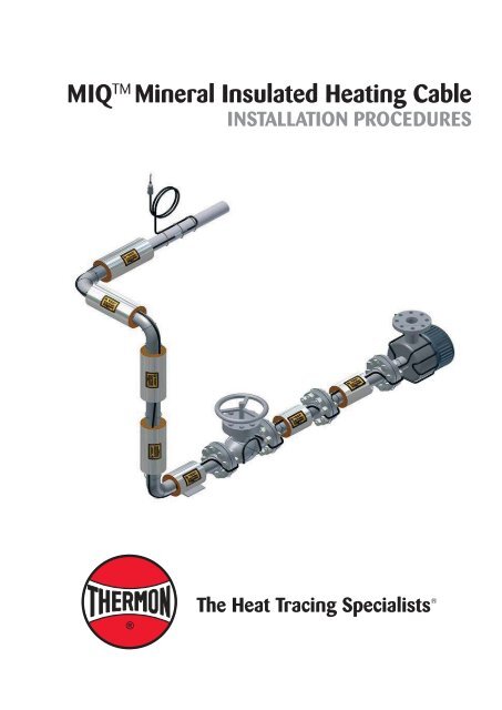
MIQ TM <strong>Mineral</strong> <strong>Insulated</strong> <strong>Heating</strong> <strong>Cable</strong>INSTALLATION PROCEDURES
INSTALLATION PROCEDURES<strong>Heating</strong> <strong>Cable</strong> Installation General Information1. Identify the heating cable to ensure the proper typeand quantity have been received. Factory-fabricatedseries circuits will have an imprinted I.D. tag withpertinent data. Compare information on heating cablewith packing slip and purchase order to verify receipt ofcorrect shipment.2. Visually inspect materials for damage incured duringshipment.3. Store in clean dry place. MIQ cable set cold lead endsmust be kept dry before, during, and after installation.4. Do not connect power to heating cable while in shippingcarton or before installed on pipe/vessel.5. Test insulation resistance of heating cable set whenreceived, when installed with pipe uninsulated and afterthermal insulation has been installed. Using a 500 Vdcmegohmmeter, the minimum acceptable reading is 20megohms between conductor and metallic sheath.IEEE 515 and EN-IEC 60079-30 recommend use ofa 1000 Vdc megohmmeter. After the application ofthermal insulation, the measured value should not beless than 5 megohms.12. <strong>Heating</strong> cable must not be embedded in the thermalinsulation.13. <strong>Heating</strong> cable set shall be spaced at least 13 mm fromany combustible surface.14. MIQ cable set cold lead ends must be kept dry before,during and after installation.15. Do not damage cable by repeatedly bending andstraightening at same location.16. Do not bend cable less than 15 cm away from hot tocold joint, splice, or end termination.17. Minimum spacing between cable is 25 mm wheninstalling multiple passes or loops.18. Refer to <strong>Thermon</strong> form TMP0066 for information onelectrical safety precautions for electrical heat tracing.19. Provisions must be made to protect MIQ cable fromwelding slag, grinders, etc.20. Keep lids on all power and splice junction boxes. Plugany unused entries.21. At tee branch in a pipeline, particularly if the branch pipeis smaller than the main pipe, double tracing the smallerpipe with the main heating unit may cause unbalancedpipe temperature. Use caution, check schedules to see ifpermissible.22. Any excess heating cable must be distributed evenlyalong pipe and equipment.23. Junction boxes must be confi gured to exclude moisture.If applicable, all conduits feeding into the junction boxshall be provided with appropriately rated drains toprevent moisture migration into the junction box.6. <strong>Heating</strong> cables shall not touch, cross over, or overlapitself after installation.7. Metal structures or material used for the support of oron which cables are sets are installed, are to be bondedto earth in accordance with applicable codes.8. Minimum installation temperature is -60°C.9. Do not alter heating cable set length.10. Do not remove metal tags from heating cable set.11. Thermostat or solid state temperature control devicemust be used when the system T-rating relies oncontrolled designs to limit sheath temperature.Types of <strong>Heating</strong> <strong>Cable</strong>s 1 . . .MIQ (refer to Form TEP0020U)1725 II 2 G Ex d IIC T1 to T6, Ta=-60°C to +55°C, IP66 orII 2 G Ex de IIC T1 to T6, Ta=-60°C to +55°C, IP66 orII 2 D Ex tD A21 IP66 T450°C to T85°C, Ta=-60°C to +55°CFMG 09.0006 Ex d (or de) IIC T1 to T6,Ex tD A21 IP66 T450°C to T85°CMI (refer to Form TEP0111U)1725 II 2G Ex e IIC Gb ISSeP12ATEX004UNotes . . .1. Refer to the heating cable product specifi cation sheets for temperatureratings as limited by the manufacturer.2
MIQ TM <strong>Mineral</strong> <strong>Insulated</strong> <strong>Heating</strong> <strong>Cable</strong>Before Installing <strong>Cable</strong> . . .1. Be sure all piping and equipment to be traced iscompletely installed and pressure tested.2. Surface areas where heat tracing is to be installed mustbe reasonably clean. Remove dirt, rust and scale witha wire brush and oil and grease fi lms with a suitablesolvent.3. Review any applicable local codes and standards prior tobeginning the installation.4. Refer to heat tracing isometric drawings for power pointlocation, equipment allowances, etc. Confi rm if MIQ setsare to be connected in series.5. Confi rm measurements of piping length, includingin-line equipment before beginning installation.6. Test insulation resistance of heating cable set whenreceived using a 500 Vdc megohmmeter. The minimumacceptable reading is 20 megohms between conductorand metallic sheath. IEEE 515 and EN-IEC 60079-30recommend use of a 1000 Vdc megohmmeter.(Record 1, Checklist on Page 9)Illustration A: Temporary Installation . . .Cold Lead WiresInitial Installation . . .1. Determine the orientation of the heating cable(s) onthe pipe. The upper 90° of the pipe should be avoidedto minimize the possibility of mechanical damage tothe heating cable. Also, the sides of the pipe should beavoided since this is the normal location of the insulationseams. Refer to Illustration B for typical heating cableorientations.2. Begin temporary installation at the proposed hot-tocoldjunction (power end) location and lay out heatingcircuit on the pipe. Refer to Illustration A for temporaryinstallation.3. Make heating cable allowances for valves, fl anges,elbows and supports as per the applicable drawings andtable on pages 4 thru 6 of these installation procedures.4. Fix hot-to-cold junction at 15 cm distance on bothsides using stainless steel tie wire or banding. Do notloop back cold lead on small diameter pipes where theminimum bending radius will be exceeded.5. Install cable with slight "wave" on pipe. Secure cable topipe with stainless steel tie wire or banding.6. Adjust cable where necessary.<strong>Cable</strong> SetHot-To-ColdFittingGland Connector<strong>Cable</strong> SetStrain ReliefFittingCold LeadValveFlangeStainless SteelTie Wireor BandingPipe Support ShoeMIQ Heater <strong>Cable</strong><strong>Cable</strong> Allowance for InlineHeat Sinks (Typ.)Illustration B: Typical Orientation of <strong>Heating</strong> <strong>Cable</strong> and Sensor Location . . .Pipe WallTemperatureSensor (Typ.)45º<strong>Heating</strong> <strong>Cable</strong>(Typ.)90º45º45º 45º45º 45ºDual <strong>Cable</strong> InstallationTriple <strong>Cable</strong> Installation3
INSTALLATION PROCEDURESInstallation on Elbows, Supports and Flanges . . .1. Install heating cable in accordance with IllustrationsC thru E below. Secure heating cable to piping usingstainless steel tie wire or banding.2. Elbows: Locate the cable on the outside radius of anelbow to provide suffi cient heat to compensate for theadded piping material. Secure the cable to the pipe oneach side of the elbow with stainless steel tie wire orbanding.3. Pipe Supports: <strong>Insulated</strong> pipe supports require noadditional heating cable. For uninsulated supports,allow two times the length of the pipe support plus anadditional 40 cm of heating cable.4. Flanges: <strong>Heating</strong> cable should maintain contact withfl ange when bending around pipe fl anges to compensatefor additional heat loss. In potentially explosive areas,it is recommended to secure MIQ cable with stainlesssteel banding at all fl anges or any other irregular shapedequipment.5. Minimum bend radius is 6X cable OD. Do not exceedbend radius when completing installation.Illustration D: Pipe Support . . .MIQ <strong>Heating</strong> <strong>Cable</strong>Stainless Steel Tie Wireor BandingIllustration C: Pipe Elbow . . .<strong>Cable</strong> To Sweep AroundOutside Diameter Of Pipe8 cmSupportLength8 cmMIQ <strong>Heating</strong> <strong>Cable</strong>Notes . . .1. Only applicable for pipe ≥ 50mm.2. Loop cable 8 cm past pipe shoesupport on both sides.Stainless SteelTie Wireor BandingIllustration E: Pipe Flange . . .Avoid BoltsMIQ<strong>Heating</strong> <strong>Cable</strong>Stainless SteelTie Wireor Banding30 cmMax.Note:Slack cable can be taken up by running the cable on the outside radiusof the pipe elbows. Running the cable on the inside radius of the pipeelbows will add slack to the cable.Table 1 Flange Allowance (pair) . . .Pipe Size mm 12 19 25 32 40 50 80 100 150 200 250 300 350 400 450 500 600 750FlangeAllowancemm 150 180 180 180 205 205 255 280 305 330 356 406 457 483 508 533 610 6604
MIQ TM <strong>Mineral</strong> <strong>Insulated</strong> <strong>Heating</strong> <strong>Cable</strong>Installation on Valves and Pumps . . .1. Install heating cable in accordance with IllustrationsF and G below. Secure heating cable to piping usingstainless steel tie wire or banding.2. Additional cable is required to provide extra heat atvalves, pumps and miscellaneous equipment to offsetthe increased heat loss associated with these items.Refer to Table 2 for estimated cable requirements forinstallation on typical valves and pumps.3. Install heating cable on valves and pumps utilizing alooping technique (this allows the valve or pump to beremoved if required). Do not cross cable.4. Minimum bend radius is 6X cable O.D. Do not exceedbend radius when completing installation.5. In potentially explosive areas, it is recommended tosecure MIQ cable with stainless steel banding at allfl anges, valves or any other irregular shaped equipment.Illustration F: Typical Valve Detail . . .Stainless Steel TieWire or BandingPipe SizemmTable 2: Valve and Pump AllowancesScrewedor WeldedmValve TypeFlangedmButterflymScrewedmPump TypeFlangedm12 .15 .30 0 .30 .6119 .23 .46 0 .46 .9125 .30 .61 .30 .61 1.2232 .46 .61 .30 .91 1.3740 .46 .76 .46 .91 1.5250 .61 .76 .61 1.22 1.6880 .76 1.07 .76 1.52 2.13100 1.22 1.52 .91 2.44 3.05150 2.13 2.44 1.07 4.27 4.88200 2.90 3.35 1.22 5.79 6.71250 3.81 4.27 1.22 7.62 8.53300 4.57 5.03 1.52 9.14 10.06350 5.49 5.94 1.68 10.97 11.89400 6.55 7.01 1.83 13.11 14.02450 7.77 8.23 1.98 15.54 16.46500 8.69 9.14 2.13 17.37 18.29600 10.36 10.97 2.44 20.73 21.95750 12.19 12.80 3.05 24.38 25.60MIQ <strong>Heating</strong><strong>Cable</strong><strong>Heating</strong> <strong>Cable</strong> Serpentined on ValveNotes. . .1. The valve allowance given is the total amount of additional cable to be installed onthe valve. If multiple tracers are used, total valve allowance may be divided amongthe individual tracers. The total valve allowance may be alternated among tracers formultiple valves in a heat trace circuit.2. Allowances are for 150 pound valves. More cable is required for higher ratedvalves.3. Refer to heat trace isometric drawing for project specifi c allowances.Illustration G: Typical Pump Detail . . .MIQ<strong>Heating</strong> <strong>Cable</strong>Stainless Steel TieWire or Banding<strong>Heating</strong> <strong>Cable</strong> Serpentined on PumpNOTE: Individual MIQ cable setrecommended for pumps.5
INSTALLATION PROCEDURESIllustration H: Pipe Hanger . . .Illustration I: Socket Weld Valve . . .<strong>Heating</strong> <strong>Cable</strong>Stainless Steel Tie Wireor BandingMIQ Heater <strong>Cable</strong>Stainless Steel Tie Wireor BandingMIQ Heater <strong>Cable</strong>Tie Wire orBanding (TYP.)Pipe HangerNotes. . .1. For small valves (less than 50 mm) it may be impractical to install the correct cableallowance on the valve body itself. It can be installed in a uniform manner across thevalve and either side of the pipe as shown above .2. At tee branch pipe line (less than 50 mm) if the branch pipe is double traced andthe main pipe is single traced, then there is no additional requirement for cableallowance for valve.Installation on Tanks and Vessels . . .Always install MIQ cable longitudinally on surface of tanksor vessels. Never spiral wrap MIQ around circumference oftanks or vessels.6
MIQ TM <strong>Mineral</strong> <strong>Insulated</strong> <strong>Heating</strong> <strong>Cable</strong>Completing the Installation . . .1. Begin fi nal cable attachment by securing the end ofcircuit and working back toward the power supply.• MIQ mineral insulated heating cables are typicallyinstalled with tie wires or stainless steel banding at30 cm intervals. Use only <strong>Thermon</strong> approved banding.Do not over tighten banding or tie wire. These cablesmay also be installed with heat transfer compound andmetal channels.• Avoid crossing series constant watt heating cables.• If applicable, refer to installation details provided withthe project drawings or contact <strong>Thermon</strong> for additionalinformation regarding installation.2. Before making power connections, the MIQ cableshould be tested to ensure electrical integrity with atleast a 500 Vdc megohmmeter (megger) between theconductors and the metal sheath. IEEE 515 andEN-IEC 60079-30 recommend a test voltage of 1000Vdc for mineral insulated cable. Minimum resistanceshould be 20 megohms.(Record 2, Checklist on Page 9)3. MIQ series resistance heating circuits are typicallyprefabricated at the factory. Junction boxes to completea typical MIQ circuit connection to power may not besupplied as part of the system. For Ex d sets, use onlyEx d connection fi ttings. For Ex de sets, use only Exe connection fi ttings. Refer to Installation instructionsincluded with power/splice enclosures or contact<strong>Thermon</strong> for additional information.4. Route MIQ cable set cold lead(s) into junction boxhub(s). Slowly tighten gland connector with set ofwrenches until ferrule begins to make positive contactwith cold lead sleeve and cold lead can not be moved byhand. Then tighten fi tting 1/8 additional turn.5. Secure temperature sensor (if required) to pipe utilizingstainless steel banding. Locate temperature sensor asshown in Illustration B.Illustration J: Typical Installation. . .Hot to Cold JunctionMI <strong>Heating</strong> <strong>Cable</strong>Stainless Steel Tie Wireor Banding (Typ.)15 cm 15 cmGland ConnectorCold Lead7
INSTALLATION PROCEDURESCircuit Protection Requirements . . .1. Over-current protection (typically circuit breakers) isrequired for each branch circuit. This protection mustisoloate all power conductors from the supply.2. For typical installations (with TT and TN groundingsystems), a means of protection against earth faultsis required that includes a residual-current protectivedevice for each branch circuit. For fi xed-level groundfaultcircuit interrupters (such as GFCI circuit breakers),a minimum 30 mA trip level is recommended. Thepreferred trip level for adjustable devices is 30 mAabove any inherent capacitive leakage characteristicof the heater as specifi ed by the heat tracing supplier.Where conditions of maintenance and supervisionensure that only qualifi ed persons will service theinstalled systems, and continued circuit operation isnecessary for the safe operation of the equipment orprocesses, earth-fault detection without interruptionis acceptable if alarmed in a manner to assure anacknowledged response.3. For IT grounding systems, a means of protectionagainst earth faults is required that includes an electricalinsulation monitoring device that shall disconnect thesupply whenever the electrical resistance is not greaterthan 50 ohms/volt of rated voltage.Thermal Insulation . . .1. The need for properly installed and well-maintainedthermal insulation cannot be overemphasized. Withoutinsulation, heat losses are generally too high to be offsetby a conventional heat tracing system.2. In addition to piping and in-line equipment such aspumps and valves, all heat sinks must be properlyinsulated. This includes pipe supports, hangers, fl angesand, in most cases, valve bonnets.3. Regardless of the type or thickness of insulation used, aprotective barrier should be installed. This protects theinsulation from moisture intrusion, physical damage andhelps ensure the proper performance of the heat tracingsystem. Seal around all penetrations through the thermalinsulation.4. After the installation of the thermal insulation andweather barrier but BEFORE ENERGIZING THEHEATING CIRCUIT, the megohmmeter test should berepeated. The measured value should not be less than5 megohms. This should call attention to any damageto the heating cable that may have occurred during theinsulation installation. (Record 3, Checklist on Page 9)Final Inspection and Documentation . . .1. It is recommended that the circuit be temporarilyenergized so that the volts, amps, pipe temperature andambient temperature may be recorded. This informationmay be of value for future reference and should bemaintained for the historical operating data log.(Record 4, Checklist on Page 9)2. A sample historical operating data log form isincluded in the Electric Heat Tracing Maintenance andTroubleshooting Guide, <strong>Thermon</strong> Form TEP0066.3. Stabilized design can be used for MIQ heating cableswithout a limiting device to determine the T-classthrough the use of the <strong>Thermon</strong> CompuTrace softwareor <strong>Thermon</strong> Engineering.4. The maximum temperatures provided by <strong>Thermon</strong>’sCompuTrace software and by <strong>Thermon</strong> engineering arecalculated to the methods and requirements ofEN-IEC 62086-2 and EN-IEC 60079-30.5. If stabilized design is used, the end user must record thesystem parameters and the area T-class, and keep theserecords for the time the heating cable is in operation.6. Inspect system on a regular basis at least once peryear. Record all information after conducting test. If thesystem fails any test, refer to <strong>Thermon</strong>’s Maintenanceand Trouble Shooting Guide for assistance. De-energizecircuits affected and make the necessary repairsimmediately.7. Verify the setting of the maximum control device, ifprovided to limit the T-rating for the circuit design, toinsure it limits the maximum surface temperature to bein compliance with clause 4.4.3 of EN-IEC 60079-30-1.Maintenance and Repair . . .1. Refer to form TEP0066-Electric Heat TracingMaintenance and Trouble Shooting Guide.Due to the risk of electrical shock, arcing and fi re caused byproduct damage or improper usage installation or maintenance,a earth/ground-fault protection device is required for all heattracing circuits. Bond the metal sheath of the heat tracing cableto a suitable earth terminal.5. Apply caution labels to insulation weather barrier atrequired intervals along pipe.8
General InformationChecklist for Installation of MI <strong>Cable</strong>sProject Number:Unit Number:Customer Ref. Number:Electrical Contractor:Reference Number:Inspector:Record 1: Prior to Installation<strong>Cable</strong> Type:Reel Length (M):Reel Number:Tested By/Date:Insulation Resistance (M Ohms):1 2Single Phase L-EarthL 1 -Earth1 23 PhaseL 2 -EarthL 3 -EarthWitnessed By/Date:Record 2: After <strong>Cable</strong> InstallationLine Number:Equipment Number:Circuit/Heater Number:Junction Box Number:Unused EntriesPlugged Off:Heater Length (M):1 2Circuit Switch Number:Metal Sheath Connectedto Earth/Ground:Thermostat Number:Tested By/Date:Record 3: After Thermal Insulation is InstalledInsulation Resistance (M Ohms):Single Phase3 PhaseWitnessed By/Date:Insulation Watertight:L-EarthL 1 -EarthL 2 -EarthL 3 -EarthInsulation Resistance (M Ohms):Electrical Loop Resistance (Ohms):Single Phase L-Earth Single Phase L-LL 1 -EarthL 1 -L 23 PhaseL 2 -Earth 3 PhaseL 2 -L 3L 3 -Earth L 3 -L 1Tested By/Date:Witnessed By/Date:Record 4: Final CommissioningPanel Number:Breaker Number:Volts:Tested By/Date:Ambient Temp. (°C):Pipe Temp. (°C):Recorded Amps(after 5 min.):Witnessed By/Date:*NOTE: Minimum acceptable insulation resistance should be 20 megohms for Records 1 and 2 and5 Megohms for Record 3.
For additional product information on <strong>Thermon</strong> heating cables, refer to the individual product specifications.Electric Heat Tracing Maintenance and Troubleshooting Guide (refer to Form TEP0066)MIQ (refer to Form TEP0020U)MIS (refer to Form TEP0111U)THERMON . . . The Heat Tracing Specialists ®www.thermon.comEuropean HeadquartersBoezemweg 25 • PO Box 2052640 AE Pijnacker • The NetherlandsPhone: +31 (0) 15-36 15 370Specifi cations and information subject to change without notice.Corporate Headquarters100 <strong>Thermon</strong> Dr. • PO Box 609San Marcos, TX 78667-0609 • USAPhone: +1 512-396-5801PN50273U-0412For the <strong>Thermon</strong> offi ce nearest youvisit us at . . .www.thermon.com