Digital Systems Laboratory - Eskişehir Osmangazi Üniversitesi
Digital Systems Laboratory - Eskişehir Osmangazi Üniversitesi
Digital Systems Laboratory - Eskişehir Osmangazi Üniversitesi

You also want an ePaper? Increase the reach of your titles
YUMPU automatically turns print PDFs into web optimized ePapers that Google loves.
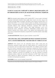
Each of the strobe signals IG {I = 1, 2} acts as an enable signal for the corresponding multiplexer.Table 11 shows the multiplex function of 74153 in terms of select lines. Note that each of the on-chipmultiplexers act independently from the other, while sharing the same select lines S1 and S0.Multiplexer 1Strobe Select lines Output1G S1 S0 1Y1 X X 00 0 0 1D00 0 1 1D10 1 0 1D20 1 1 1D3Table 11Multiplexer 2Strobe Select lines Output2G S1 S0 2Y1 X X 00 0 0 2D00 0 1 2D10 1 0 2D20 1 1 2D3Fig. 24 Chip 74153IC 7447 is a BCD to seven segment decoder driver. It is used to convert the combinational circuit outputsin BCD forms into 7 segment digits for the 7 segment LED display units. See Lab. 5.Procedure:Part I: Parity Generator:a. Design a parity generator by using a 74151 multiplexer. Parity is an extra bit attached to a code tocheck that the code has been received correctly. Odd parity bit means that the number of 1’s in the codeincluding the parity bit is an odd number. Fill the output column of the truth table in Table 12 for a 5-bitcode in which four of the bits (A, B, C, D) represents the information to be sent and fifth bit (x), representsthe parity bit. The required parity is an odd parity. The inputs B, C and D correspond to the select inputs of74151. Complete the truth table in Table 12 by filling in the last column with 0, 1, A or A’.b. Simulate the circuit using LogicWorks, use 74-151 multiplexer and Binary switches for inputs andbinary Probes for outputs. The 74151 has one output for Y and another inverted output W. Use A and A’for providing values for inputs 0-7. The internal values “A, B, C” are used for selection inputs B, C, and D.Simulate the circuit and test each input combination filling in the table shown below.26