Phocos CIS - Solar-Bazaar
Phocos CIS - Solar-Bazaar
Phocos CIS - Solar-Bazaar

You also want an ePaper? Increase the reach of your titles
YUMPU automatically turns print PDFs into web optimized ePapers that Google loves.
<strong>Phocos</strong> <strong>CIS</strong>BedienungsanleitungUser ManualManual de InstruccionesGuide de l'utilisateurManual do Usuãrio用 户 说 明 书CID:181814611
CONTENTSBedienungsanleitungUser ManualManual de InstruccionesGuide de l'utilisateurManual do Usuãrio用 户 说 明 书1-1011-3031-4041-5051-6061-70
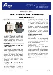
Bitte lesen Sie die Anweisungen sorgfälltig und gründlich durch, bevor Sie das Produkt in Betriebnehmen. Es ist ausgestattet mit einer Reihe von herausragenden Eigenschaften, wie z. B.:DE Schutzklasse: IP68 -72 Stunden in einer Wassertiefe von 1,50 m. Doppel- Last. Kontroll-Einheit (CU) zur Konfiguration des <strong>CIS</strong> Laderegler mittels Infrarot-Datenverbindung. Externer Temperaturfühler für die Temperaturkompensation der Ladespannungen. umfassende Programmierbarkeit. 3-stufige s Ladeverfahren (Boost-Ladung, Ausgleich, Erhaltung) für Flüssigsäure-Akkus, 2-stufige Aufladung (Hauptladung, Erhaltungsladung) für verschlossene Batterien. Automatische Erkennung der Systemspannung 12/24 V.Anschluss und Erdung Um Störungen zu vermeiden schließen Sie die Kabel in der Reihenfolge 1234567, wie in derInstallationsanleitung beschrieben an. Zur Vermeidung jeglicher Spannung an den Kabeln, zuerst das Kabel mit dem Ladereglerverbinden, dann die Batterie oder die Verbraucher anschließen. Empfohlene minimale Kabelquerschnitte: <strong>CIS</strong>05: 1,5 mm ², <strong>CIS</strong>10: 2.5 mm ², <strong>CIS</strong>20: 4 mm ². Stellen Sie sicher, dass die Kabellänge zwischen Batterie und Laderegler möglichst kurz gewählt ist. Vergewissern Sie sich, dass sämtliche Pluspole des <strong>CIS</strong>-Laderegler zusammengefasstangeschlossen und auf einen elektrische Potential verschaltet wurden. Wenn eine Erdungerforderlich ist, ist dies immer mit dem positiven Kabel zu bewerkstelligen.1
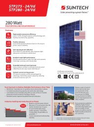
DEElektronische Verbraucher, wie Relais,Steuereingänge oder Motoren, können denLaderegler durch magnetische Induktion beim Ausschalten beschädigen. Um dieszu verhindern, schließen Sie die Diode (wie 1N5401...1N5408) in Sperrrichtungzwischen Positiver Lastanschluss und Negativer Lastanscluss.Funktion Kabelkennzeichnung Kabelquerschnitt Farbe12PositiverBatterieanschlussNegativerBatterieanschlussCOMMON + 2.5 mm2 rotBATTERY - 2.5 mm2 schwarz3 Positiver Panelanschluss COMMON + 2.5 mm2 rot4 Negativer Panelanschluss SOLAR - 2.5 mm2 blau5 Positiver Lastanschluss COMMON + 2.5 mm2 rot6 Negativer Lastanscluss LOAD - 2.5 mm2 grün7 Dimm-Signal Anschluss --- 0.6 mm2 schwarz2
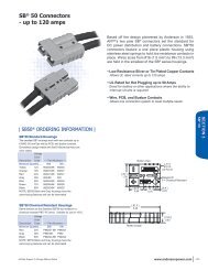
DEZum Dimm-Steuereingang der Lampe3
DEAnzeige & WarnfunktionenLED Staus FunktionEinLaderegler an den Akkumulator angeschlossen, NachterkennungBlinken Laderegler an die Akkumulator angeschlossen, Tag erkanntAuskein Akkumulator angeschlossenEinLast Tiefentladeschutz-/Überspannungs-Lastabwurf (LVD / HCD)Blinken Last ÜberstromAusLast okAlle LEDOndimmen aufgrund (LVD / HVD)Offzeitgesteuertes Dimmengrün, rot, grün ProgrammierungNachtlicht-FunktionDieser <strong>CIS</strong>-Laderegler ist mit einer hochentwickelten Nacht-Licht-Funktion ausgestattet. Ersteuert den Lastausgang nachts und ist umfassend programmierbar. Beide Ausgänge sind freiprogrammierbar.Es stehen 3 Modalitäten zur Verfügung:Standard-Controller, Abenddämmerung-bis-Morgendämmerung und Abend/Morgen-Modi.4
DE“ Mitter der Nacht“ wird automatisch als Mittelpunkt zwischen Dämmerung und denMorgenstunden betrachtet, dadurch ist keine Zeiteinstellung erforderlich. Es kann mehrereTage dauern, bis der Laderegler die Mitternacht exakt "registriert“ hat. "Mitte der Nacht" kann jenach Standort von 12:00 Uhr abweichen.Der Laderegler erkennt Tag und Nacht aufgrund der Leerlaufspannung des <strong>Solar</strong>generator.Diese Tag / Nacht-Schwelle kann an die örtlichen Lichtverhältnisse und den <strong>Solar</strong>generatorangepasst werden.5
DESicherheits-Merkmale<strong>Solar</strong>-Anschluß Batterie-Anschluß LastanschlussVerpolungsschutz Geschützt (1) Geschützt (1) Geschützt (2)Kurzschluss Geschützt Geschützt (3) Schaltet sofort abÜberstrom N / A N/A Schaltet ab mit VerzögerungRückstrom Geschützt N/A N/AÜberspannung Max. 55 V (4) Max. 40 V Schaltet ab über 15,5 V / 31,0 VUnterspannung N/A N/A Schaltet abÜbertemperaturReduziert den Ladestrom via PWM, wenn Übertemperatur auftritt undschaltet die Last ab, wenn die Temperatur ein hohes Niveau erreicht hat.(1) Der Laderegler besitzt kein Eigenschutz für ein 24 V-System; Modul-Batteriespannung istbegrenzt auf 40 V.(2) Der Laderegler kann sich selbst schützen aber Verbraucher können zerstört werden.(3) Die Batterie muss durch eine Sicherung geschützt werden, ansonsten kann die Batteriedauerhaft geschädigt werden.(4) Die <strong>Solar</strong>modul-Spannung sollte diese Grenze nicht über einen längeren Zeitraum hinwegüberschreiten. Ein Überspannungsschutz wird durch einen Varistor realisiert.WARNUNG: Die Kombination verschiedener Fehler kann zu Schäden am Laderegler führen.Beheben Sie stets zuvor den Fehler, bevor Sie den Laderegler wieder in Betrieb nehmen.6
TestfunktionDEDas Drücken der Test-Taste auf der CU (Kontroll-Einheit) bewirkt, dass beide Lastklemmen für 2Minuten eingeschaltet werden.Wenn beim drücken der Taste ein Lastabwurf ausgelöst wird (LVD / SOC, Überstrom) wird die Lastabgeschaltet.Tiefentladeschutzfunktion (LCD)Ladezustandsgesteuert (SOC): Abschalten bei11.00 V/22.00 V bis 11,70 V/23.40 V (SOC1),11,12 V/22,24 V bis 11,76 V/23,52 V (SOC2),11.25 V/22,50 V bis 11,83 V/23,63 V (SOC3),11,38 V/22,72 V bis 11,89 V /23,78 V (SOC4),11,51 V/23,02 V bis 11,96 V/23,92 V (SOC5),11,64 V/23,28 V bis 12,02 V/24,04 V (SOC6).Spannungsgesteuert (LVD): Abschalten bei einer festen Spannung zwischen 11,0 V/22,0 Vund 11.9 V/23.8 V(Schrittweise 0.1 V).Hinweis: Die beiden Spannungen vor und nach dem Schrägstrich, gelten jeweils für 12 V und 24 V-Systeme.7
DEWerkseinstellungenSie können den <strong>CIS</strong> Laderegler über die Kontrolleinheit (CU) konfigurieren. Siehe hierzu CUHandbuch.Last-ModusTiefentladeschutzBatterietypWerkseinstellungStandard LadereglerSOC4Dimmwert 50 %HaftungsausschlussVerschlossenDer Hersteller haftet nicht für Schäden, insbesondere an der Batterie, die durch eine nicht wievorgesehene oder wie im Handbuch beschriebene Verwendung entstehen, oder wenn dieEmpfehlungen Batterieherstellers missachtet werden.Der Hersteller haftet nicht, wenn Reparaturen oder Services von nicht autorisierten Personendurchgeführt wurden. Ebenso bei unsachgemäßem Gebrauch, falscher Installation oder falscherSystemauslegung.8
Technische DatenDESystemnennspannung12/24 V, automatische SpannungserkennungBoost-SpannungSpannungshauptladung 14.4/28.8 V (25 ° C), 2 hAusgleichsspannung14.8/29.6 V (25 ° C), 2 hErhaltungsspannung 13.8/27.6 V (25 ° C)LastabwurfspannungLastzuschaltspannungAbendstunden/Vormittagsstunden11,00-12,02 V/22.00-24.04 V durch SOC11,0-12,0 V/22.0-24.0 V durch Spannung12.8/25.6 VDimmwert 0…100 %Dimm-AusgangsspannungTag / NachterkennungAkkumulator-TypTemp.-KompensationMax. <strong>Solar</strong>stromMax. LaststromAbmessungen0-15 Stunden/0-14 Stunden0 V bis 10 V relativ zu Batterie-Minus2.5-10 VFlüssigsäure, verschlossen-4,2 mV / K pro Zelle5/10/20, je nach Modell-Nummer @ 60 ° C5/10/20, je nach Modell-Nummer @ 60 ° C82 x 58 x 20 mm9
DEKabelquerschnitt AWG 13 (2.5 mm 2 )Typische LeistungsaufnahmeKleiner 8/10 mAUmgebungstemperatur-Bereich* -40 Bis +60 ° CGeräteschutzklasse IP68 (1,5 m, 72 h)Maximale Höhe über N.N./Gewicht 4000 m / 150 g*: Ab 60 ° C, kann der <strong>CIS</strong>-Laderegler entweder den max. <strong>Solar</strong>modul- oder den max. Laststromverarbeiten, jedoch nicht beide Ströme gleichzeitig.Änderungen jeder Art vorbehalten, selbige können ohnevorherige Benachrichtigung am <strong>CIS</strong>-Lageregler vorgenommen werden.Version: 20130412Hergestellt in einem der folgenden Länder:Deutschland - China - Bolivien - Indien<strong>Phocos</strong> AG - Deutschland www.phocos.comISO9001RoHS10
Please read the instructions carefully and thoroughly before using the product. It comes with anumber of outstanding features, such as:Case protection: IP68 protection, in 1.5 m water depth 72 Hours.Dimming functionControl unit (CU) to configure <strong>CIS</strong> charge controller via infra-red data linkExternal temperature sensor for temperature compensation of charge voltagesWidely programmable3 stage charging (boost, equalization, float) for flooded battery, 2 stage charging (boost,float) for sealed batteryAutomatic recognition of system voltage 12/24 VPositive groundingENIMPORTANT SAFETY INSTRUCTIONSSAVE THESE INSTRUCTIONSThis manual contains important instructions for <strong>CIS</strong>-05-1.1, <strong>CIS</strong>-10-1.1, <strong>CIS</strong>-20-1.1, <strong>CIS</strong>-05-1.1-2L,<strong>CIS</strong>-10-1.1-2L, <strong>CIS</strong>-20-1.1-2L models that shall be followed during installation and maintenanceof the charge controller.INSTRUCTIONS DE SÉCURITÉS IMPORTANTESCONSERVER CES INSTRUCTIONSCette notice contient d’importantes instructions visant les modèles <strong>CIS</strong>-05-1.1, <strong>CIS</strong>-10-1.1, <strong>CIS</strong>-20-1.1, <strong>CIS</strong>-05-1.1-2L, <strong>CIS</strong>-10-1.1-2L, <strong>CIS</strong>-20-1.1-2L, lesquelles doivent être suivies au moment de11
ENl’entretien de l’appareil.If connection to the power lead or battery lead are accessible during operational maintenancethe following warning shall be marked adjacent to the connection where practical orprominently displayed on the enclosure: WARNING - EXPLOSION HAZARD - DO NOTDISCONNECT WHILE CIRCUIT IS LIVE UNLESS AREA IS KNOWN TO BE NON-HAZARDOUS. andAVERTISSEMENT - RISQUE D’EXPLOSION. NE PAS DÉBRANCHER TANT QUE LE CIRCUIT EST SOUSTENSION, À MOINS QU’IL NE S’AGISSE D’UN EMPLACEMENT NON DANGEREUX.EXPLOSION HAZARD. DO NO DISCONNECT WHILE THE CIRCUIT IS LIVE OR UNLESS THE AREA ISKNOWN TO BE FREE OF IGNITIBLE CONCENTRATIONS.THIS EQUIPMENT IS SUITABLE FOR USE IN CLASS I, DIVISION 2, GROUPS A-D, T4A.UL 1741 andUL 1604, ANSI/ISA 12.12.01-2011, C22.2 No. 213-M1987.RISK OF FIRE – MOUNT IN CONTACT WITH BATTERIESBattery type: Lead acid, (GEL, AGM, flooded)Nominal voltage rating of the battery: 12 or 24 VBatteries fuse: use a fast acting fuse with a minimum of 1000A interrupting rating on thebattery side. We recommend to use fast acting melting fuses (e.g. car type fuses) on the batteryside, as close as possible at the battery terminal with 1.5 times the current rating of themaximum nominal current (see table).12
Fuse ratings:<strong>CIS</strong> type <strong>CIS</strong>-05 <strong>CIS</strong>-10 <strong>CIS</strong>-20ENFuse 7.5 A 15 A 30 APlease do not disassemble or attempt to repair <strong>Phocos</strong> products. <strong>Phocos</strong> charge controllers donot contain user serviceable parts.Please observe all instructions with regards to external fuses/breakers as indicated.Maintenance and installation notesWhen installing or working on the PV system, please disconnect the PV (solar) modules fromthe charge controller first, to prevent any damages to the charge controller!Please verify that all cable/wire connections are tightly fastened to the connectors/connectingposts in order to avoid any bad or loose connections that could result in excessive heating.Please install a fuse or breaker near the battery before installing or adjusting the controller!Please install and operate the controller in a dry environment.High voltage risksOperation of this device may produce a high voltage which could cause severe injuries or deathin case of improper installation or operation of the device.PV modules can generate high DC voltages!Make sure the cables are always connected to the correct terminal. An electrical shock c an belethal. In general, any electric shock can be dangerous to your health.13
ENCE labelingThe product is CE compliant.Mounting of the unitSince the charge controller must be able to sense the battery temperature it must be mountedinto the same compartment together with the battery. It shall be mounted as close as possibleto battery. We recommend not to use more than 1m wire length between battery and chargecontroller. This apparatus is suitable for use in Class I, Division 2 groups A, B, C, D or unclassifiedlocations.Vertical mounting on non flammable surface with minimum 2 cm distance below andabove unit.In case of higher ambient temperatures and limited heat dissipation (e.g. by surroundingcompartment or smaller mounting distances), charge controller will limit its charge currentto reduce temperature.If heat dissipation is limited by surrounding compartment, unit will limit charge current toreduce temperature.The charge controller is not intended to be installed within the wiring compartment of aPV module. The wiring methods in accordance with the National Electrical Code,ANSI/NFPA 70 are to be used.14
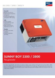
2 cmEN<strong>CIS</strong>> 2 cmConnecting and Grounding Connect wires in order indicated 1 2 3 4 5 6 7 to avoid installation faults To avoid any voltage on the wires, first connect the wire to the controller, then to thebattery, panel or load. Recommended minimum wire size: <strong>CIS</strong>-05: 1.5 mm 2 ; <strong>CIS</strong>-10: 2.5 mm 2 ; <strong>CIS</strong>-20: 4 mm 2 Make sure the wire length between battery and controller is as short as possible. Be aware that the Positive terminal of <strong>CIS</strong> are connected together and therefore have thesame electrical potential. If any grounding is required, always do this on the Positive wires.15
ENSome equiptment, like relays, gates or motors, can damage the controller by magneticinduction, when it switches off. To prevent this, reverse connect the diode (such as 1N5401 ..1N5408) between LOAD positive and LOAD negative.Connectors used in incendive circuits and incorporated within equipment shall beconsidered normally non-arcing if disconnection is not required under operationalmaintenance conditions, and if they are so secured that a separating force of at least 15 Nis required for loosening.Function Cable marker Wire size (cross section) color1 Positive battery terminal COMMON + AWG 13 (2.5 mm2) Red2 Negative battery terminal BATTERY - AWG 13 (2.5 mm2) Black3 Positive panel terminal COMMON + AWG 13 (2.5 mm2) Red4 Negative panel terminal SOLAR - AWG 13 (2.5 mm2) Blue5 Positive load terminal COMMON + AWG 13 (2.5 mm2) Red6 Negative load terminal LOAD - AWG 13 (2.5 mm2) Green7 Dimming signal terminal --- AWG 19 (0.6 mm2) Black16
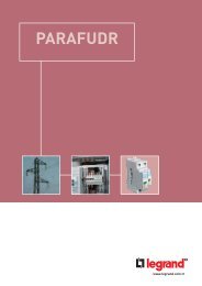
ENTo dimming terminal of lamp17
<strong>CIS</strong> operational descriptionENThe <strong>CIS</strong> charge controllers are built to be operated with 12V or 24V vented and sealed lead acidbatteries. A series PWM-charge controller like the <strong>CIS</strong> connects the PV-panel to the battery, tocharge it or disconnects it when the battery voltage is high enough. Depending on the batteryvoltage it will frequently switch ON and OFF the charge current to regulate the battery voltage.This voltage depends on the charge state (Main charge/ Boost/ Equalisation/ Float)The <strong>CIS</strong> will disconnect the PV-panel from battery at night to prevent any current to flow backfrom the battery to the panel at night. These functions are achieved by the use of modernsemiconductor switches, called power-MOS-FETs. one is used to switch on/off the chargecurrent, the other one acts as actively switched diode to prevent back current from flowingfrom the battery backwards to the PV-panel at night. The <strong>CIS</strong> also provide one or two (-2L)power outputs to supply electronic loads with electricity. The output voltage of these loadoutputs is the battery voltage.To protect the battery from getting deep discharged, the charge controller will disconnect theload output at a low SOC (state of charge). This level is adjustable. To protect connected load,the <strong>CIS</strong> will also disconnect the load at too high battery voltage levels. This function is alsorealized by a power-MOS-FET, one for each load output. To achieve temperature compensationof the charge voltage, the <strong>CIS</strong> have got an external temperature sensor to sense the ambient(battery) temperature. The charge controller will adapt the charge voltage according to thisexternal temperature, to provide a charge voltage compensation of -4mV per degree Celsiusand battery cell (24mV/K for a 12V battery, 48mV/K for a 24V battery).18
To provide over-temperature protection functions, it has also a built in temperature sensor. Ifthe internal temperature gets higher than about 75°C (e.g. at high charge currents and highambient temperatures, the charge current will be decreased, to limit the internal power lossand thus to reduce internal heating. If the internal temperature is too high, it will also switch offthe load current. This shall prevent the charge controller from being damaged by too highinternal temperatures.EN<strong>CIS</strong> units with one load output have got an additional DIM-output that provides a signalbetween 0 .. 10V to control the brightness of a lamp by use of a compatible LED driver. Widelyadjustable settings can control the load output(s) and DIM output to provide various night lightfunctions. These can be programmed/adjusted by use of the CU, an infrared remote controlespecially designed for the <strong>CIS</strong> series.This all is realized by the use of a micro-controller inside the <strong>CIS</strong>. This micro controller is a smallcomputer, equipped with software (firmware) and integrated peripherals to measure voltages,currents and digital signals, and output digital signal, to switch on and off transistors,controlling the FETs, LEDs, etc.19
Display & Warning FunctionsENLED Status FunctionOnFlashOffOnFlashOffOnOffController connected to battery, night detectedController connected to battery, day detectedNo battery connectedLoad 1 low/high voltage disconnect(LVD/HVD)Load 1 over currentLoad 1 OKDimming because of low/high voltage disconnectTime control dimmingAll LED Green->Red->Green-> Programming20
Night-Light FunctionThe <strong>CIS</strong> controller comes with a sophisticated night-light function. It controls the load output atnight and is widely programmable.There are 3 modes available:Standard Controller, Dusk to Dawn and Evening/Morning modes.EN"Middle of night" is detected automatically as the midpoint between dusk and dawn, no setting of aclock is required. It may take several days until the controller has "learned" the middle of the nightprecisely. "Middle of night" may be different from 12:00 midnight depending on your location.The controller recognizes day and night based on the solar array open circuit voltage.21
ENThis day/night threshold can be modified according to local light conditions and the solar arrayused.Dimming FunctionOutput voltage 0 V to 10 V relative to battery minus(adjust step 1 V).Load hours(load 1 on CU case printing) and Dimming hours(load 2 on CU case printing)work together to effect dimming function:No dimming Dimming on Load offLoad hours on on offDimming hours on off N/ADimming output voltage 10 V Voltage proportional to dimming level 0 VCorresponding relationship of 'Output voltage' and 'Dimming value'Output voltage 0 V 1 V 2 V 3 V 4 V 5 V 6 V 7 V 8 V 9 V 10 VDimming value 0% 10% 20% 30% 40% 50% 60% 70% 80% 90% 100%22
Testing FunctionPushing the test button on the CU (Control Unit) will switch on load terminal for 1 minute.If pressing the button causes a load disconnect event (LVD/SOC, over current) the load will beswitched off immediately.ENSafety FeaturesPV terminal Battery terminal Load terminalReverse polarity Protected (1) Protected (1) Protected (2)Short circuit(3) Protected (8) Protected (4) Switches off immediately(8)Over current N/A N/A Switches off with delay(5)Reverse current Protected(6) N/A N/AOver voltage Max. 55 V (7) Max. 40 V Switches off above 15.5/31.0 VUnder voltage N/A N/A Switches offOver temp.Reduces the charging current by PWM if over temperature occurs andswitches off the load if the temperature reaches a high level.(1) Upanel-Ubattery is limited to 60 V.(2) Controller can protect itself, but loads might be damaged.(3) Short circuit: >3x – 20x nominal current.(4) Battery must be protected by a fuse, or the it can be permanently damaged in case of a23
ENshort circuit.(5) >200% nominal current: disconnect with 3s delay,>150% nominal current: disconnect with 10s delay,>110% nominal current: disconnect with 120s delay.(6) Reverse current through solar panel is blocked by serial MOSFET. This function is tested andactivated approx. once in 1min +/-5s.(7) The solar panel voltage should not exceed this limit for a long time as voltage protection isdone by a varistor.(8) Limited electronic protection; must be additionally protected by an external fast acting fuseagainst short circuit to prevent damage from charge controller; nominal fuse rating shall be1.5 times the maximum charge current.WARNING: The combination of different error conditions may cause damage to the controller.Always remove the error before you continue connecting the controller!Low Voltage Disconnect Function (LVD)State of charge (SOC) controlled: Disconnect at11.00/22.00 V to 11.70/23.40 V(SOC1), 11.12/22.24 V to 11.76/23.52 V(SOC2),11.25/22.50 V to 11.83/23.63 V(SOC3), 11.38/22.72 V to 11.89/23.78 V(SOC4),11.51/23.02 V to 11.96/23.92 V(SOC5), 11.64/23.28 V to 12.02/24.04 V(SOC6).Voltage controlled (LVD): Disconnect at a fixed voltage between 11.0/22.0 V and 11.9/23.8 V(Step 0.1/0.2 V).Note: Battery voltage must be below setting for longer than 2 minutes for LVD to take effect.24
Note: The two voltage levels before/after the slash are valid for 12 V and 24 V systemsrespectively (valid for the charge controllers in this manual).Factory SettingsENYou can configure <strong>CIS</strong> charge controllers via the Control Unit (CU). See CU manual for details.Factory settingLoad mode Standard controller(night light off )Low voltage disconnectSOC4Battery typeGelNight light level 8.0/16.0 V (1)Load 1 evening hours0 hLoad 1 morning hours0 hDimming evening hours0 hDimming morning hours0 hDimming value 50 %(1) PV panel open circuit voltage: Day level = Night level + 1.5/3.0 V25
Night light levelENThe controller recognizes "day" and "night" based on the solar PV array open circuit voltage. Thedaylight threshold can be modified according to the requirements of the local conditions andthe solar PV array used.To find the correct values, we recommend measuring the PV solar array open circuit voltage atthe time when twilight has reached the level when the controller should switch the loads "on"or "off". This value (the closest available) can then be set according to the description in theprogramming section.26
Technical DataNote: The two voltage levels before/after the slash are valid for 12 V and 24 V systems respectively.ENTechnical Data <strong>CIS</strong>-05 <strong>CIS</strong>-10 <strong>CIS</strong>-20System voltage12/24 V auto recognitionMax. charge current 5 A** 10 A** 20 A**Max. load current 5 A** 10 A** 20 A**Float chargeMain chargeBoost chargeEqualizationDeep discharge protectionCut-off voltage13.8/27.6 V(25 °C)14.4 V (25 °C), 0.5 h (daily)14.4/28.8 V (25 °C), 2 hactivation: battery voltage < 12.3/24.6 V14.8/29.6 V (25 °C), 2 hactivation: battery voltage < 12.1/24.2 V(at least every 30 days)11.00-12.02/22.00-24.04 V By SOC11.0-11.9/22.0-23.8 V By voltage(adjustable step 0.1/0.2 V)27
ENReconnect levelOvervoltage protectionUndervoltage protectionMaximum solar voltageTemperature compensation(Charge voltage)Max. self consumptionGroundingAmbient temperature rangeMaximum operational ambienttemperatureMax. heightBattery typeAdjustment range:Evening hoursMorning hoursNight detection12.8/25.6 V15.5/31.0 V10.5/21.0 V30 V/50V (12/24 V system voltage)-4.2 mV/K per cellLower than 8/10mAPositive Grounding−40 to +60 °C**50°C4,000 m above sea levellead acid (GEL, AGM, flooded)0 – 15 h0 – 14 h2.5 – 10.0 V / 5.0 – 20.0 V (adjust step 0.5/1.0 V)28
Day detection 4.0 – 11.5 V / 8.0 – 23.0 V (adjust step 0.5/1.0 V)Wire length10 cmDimensions(WXHXD)82 x 58 x 20 mmWeight150 gWire cross section AWG 13 (2.5 mm2)Type of protection IP68 (1.5 m, 72 h)ENDimming output <strong>CIS</strong>-05 <strong>CIS</strong>-10 <strong>CIS</strong>-20Dimming value 0 – 100 % output power (adjust step 10 %)Dimming output voltage0 V to 10 V relative to battery minus** : At an ambient temperature above 50°C, with all currents applied, the charge controller willautomatically reduce the charge current to limit the internal temperature.29
Liability ExclusionENThe manufacturer shall not be liable for damages, especially on the battery, caused by useother than as intended or as mentioned in this manual or if the recommendations of thebattery manufacturer are neglected. The manufacturer shall not be liable if there has beenservice or repair carried out by any unauthorized person, unusual use, wrong installation, orbad system design.Subject to change without notice. Version: 20130412Made in one of the following countries:Germany - China - Bolivia - India<strong>Phocos</strong> AG - Germanywww.phocos.comISO9001RoHS30
Por favor lea las instrucciones bien y con cuidado antes de usar el producto. Éste viene acompañado deun número de propiedades excelentes, tales como: Protección de la caja: protección IP 68, 72 horas en una profundidad de agua de 1,5 m. Carga doble. Unidad de control (CU) para configurar el controlador de carga <strong>CIS</strong> mediante conexión dedatos por infrarrojo. Sensor de temperatura externo para la compensación de tensión de carga Ampliamenteprogramable. 3 estapas de carga (por incremento, por compensación, flotante) para batería inundada, 2etapas de carga (por incremento, flotante) para batería plomada. Reconocimiento automático de la tensión del sistema 12/24 V.ESConexión y puesta a tierraConecte los cables en el orden indicado 1234567 para evitar fallos de conexión.Para evitar cualquier tensión en los cables, conecte primero el cable al controlador, luego a labatería, al panel o a la carga.Tamaño mínimo de cable recomendado: <strong>CIS</strong>05: 1,5 mm², <strong>CIS</strong>10: 2,5 mm² ,<strong>CIS</strong>20: 4 mm².Asegúrese de que el largo del cable entre la batería y el controlador sea lo más cortoposible.Sepa que los polos positivos de <strong>CIS</strong> están conectados juntos y que por lo tanto tienen elmismo potencial eléctrico. Si es necesaria una toma a tierra, colóquela siempre de loscables positivos.31
Algunos equipos, como relés, compuertas o motores, pueden dañar el controlador porinducción magnética, cuando se desconecta. Para prevenir esto, conectar inversamente eldiodo (como 1N5401 ... 1N5408) entre la CARGA + y la CARGA -.ESFunciónMarcado delcableTamaño del cable(sección)Color1 Terminal positivo de la batería COMMON + AWG 13 (2.5 mm2) rojo2 Terminal negativo de la batería BATTERY - AWG 13 (2.5 mm2) negro3 Terminal positivo del módulo COMMON + AWG 13 (2.5 mm2) rojo4 Terminal negativo del módulo SOLAR - AWG 13 (2.5 mm2) azul5 Terminal positivo de carga COMMON + AWG 13 (2.5 mm2) rojo6 Terminal negativo de carga LOAD - AWG 13 (2.5 mm2) verde7Terminal de señal deatenuación--- AWG 19 (0.6 mm2) negro32
ESA la Entrada de control delatenuador de la luz33
Pantalla & Funciones de alertaLED Estado FunciónESencendidoflashapagadoencendidoflashapagadoencendidoapagadoControlador conectado a la batería, noche detectadaControlador conectado a la batería, día detectadoNo hay batería conectadaBaja carga/desconexión por alta tensión (LVD/HVD)Carga bajo sobrecorrienteCarga okAtenuado debido a la LVD/HVDAtenuado por tiempo controladoTodas las LED verde-> rojo->verde-> ProgramandoFunción de lamparilla de nocheEste regulador <strong>CIS</strong> presenta una función sofisticada de lamparilla de noche, regula la salida de cargaen la noche y es ampliamente programable, las salidas son programables de forma independiente.Se dispone de 3 modos:controlador estándar y los modos del anochecer al amanecer y tarde/mañana.34
ESEl "medio de la noche" está detectado de forma automática como el punto medio entre elanochecer y el amanecer, no es necesario poner un reloj. Demorará varios días hasta que elcontrolador haya "aprendido" el medio de la noche con precisión.El "medio de la noche" puede no concordar con las 12:00 de la medianoche en dependencia de suposición.El controlador reconoce el día y la noche basado en el panel solar de la tensión en circuitoabierto. Este umbral de día/noche puede ser modificado según las condiciones locales de luz y elpanel solar utilizado.35
Función de pruebaESApretando el botón de prueba en la CU (unidad de control) se encienden ambas terminales decarga por 2 minutos.Si al apretar el botón se desconecta la carga (baja tensión (LVD)/estado de la carga (SOC),sobreintensidad de corriente) se apagará la carga.Características de seguridadTerminal solar Terminal de batería Terminal de cargaPolaridad inversa protegido (1) protegido (1) protegido (2)Cortocircuito protegido protegido (3) apagado inmediatoSobrecorriente no disponible no disponible apagado con retardoCorriente inversa protegido no disponible no disponibleSobretensión Máx. 55 V (4) Máx. 40 V apagado sobre 15.5 V / 31.0 VHipotensión no disponible no disponible apagadoAlta temperaturaReduce la corriente de carga por PWM en caso de alta temperatura y seapaga la carga si la temperatura alcanza un nivel alto.(1) El controlador no puede protegerse a sí mismo en un sistema de 24 V; panel U-batería U estálimitado hasta 40 V.36
(2) El controlador puede protegerse a sí mismo, pero las cargas pueden ser dañadas.(3) La batería tiene que ser protegida mediante fusible, de lo contrario puede dañarse de formairreparable.(4) La tensión del panel solar no debe sobrepasar este límite por mucho tiempo como proteccióncontra la tensión se utiliza un varistor.ATENCIÓN: La combinación de diferentes condiciones de error puede causar daños al controlador.¡Elimine siempre el error antes de continuar con la conexión del controlador!ESFunción de desconexión en baja tensión (directiva de baja tensión LVD) Estado de la carga (SOC) controlado: Se desconecta en11.00 V/22.00 V hasta 11.70 V/23.40 V(SOC1), 11.12 V/22.24 V hasta 11.76 V/23.52 V(SOC2),11.25 V/22.50 V hasta 11.83 V/23.63 V(SOC3), 11.38 V/22.72 V hasta 11.89 V/23.78 V(SOC4),11.51 V/23.02 V hasta 11.96 V/23.92 V(SOC5), 11.64 V/23.28 V hasta 12.02 V/24.04 V(SOC6). Tensión controlada (LVD): Se desconecta entre una tensión fija entre 11.0 V/22.0 V y 11.9V/23.8 V (Salto 0.1 V).Nota: Los dos niveles de tensión antes / después de la barra son válidos para los sistemas de 12V y 24 V respectivamente.37
Ajustes de fábricaESUsted puede configurar los controladores de carga <strong>CIS</strong> mediante la unidad de control (CU).Véase el manual de CU para más detalles.Modo de cargaDesconectado por baja tensiónTipo de bateríaAjustes de fábricaControlador estándarSOC4plomadaValor de atenuado 50 %Exclusión de responsabilidadEl fabricante no se responsabilizará de los daños, especialmente de la batería, causados porotro uso que no sea el especificado o mencionado en este manual o si no se cumple con lasrecomendaciones del fabricante de la batería. El fabricante no se responsabilizará si ha habidoun servicio o reparación realizada por una persona no autorizada, del empleo inusual, de unainstalación incorrecta o del mal diseño del sistema.38
Datos técnicosTensión nominalTensión por incrementoTensión por compensaciónTensión flotanteTensión de desconexión de cargaTensión de reconexión de cargaHoras de la tarde/horas de la mañanaValor de atenuadoTensión de salida de atenuadoDetectado de noche/díaTipo de bateríaCompensación de temperatura12/24 V, reconocimiento automático14.4/28.8 V (25 °C), 2 h14.8/29.6 V (25 °C), 2 h13.8/27.6 V (25 °C)11.00-12.02 V/22.0-24.04 V en caso de SOC11.00-12.00 V/22.0-24.00 V en caso de tensión12.8/25.6 V0-15 horas / 0-14 horas0...100 % de potencia de salida0 V a 10 V relativo al menos de la batería2.5-10 Vinundada, plomada-4.2 mV/K por célulaCorriente solar máxima 5/10/20, de acuerdo con el número de modelo en 60 °CCorriente de carga máxima 5/10/20, de acuerdo con el número de modelo en 60 °CDimensiones82 x 58 x 20 mmTamaño de cable AWG 13 (2,5 mm 2 )ES39
ESCónsumo de energía típicoMenos de 8/10 mALímite de temperatura ambiente -40 a +60 °CProtección de la caja IP68 (1.5 m, 72 h)Altura máxima/peso4000 m/150 g** :A 60 °C <strong>CIS</strong> sólo puede tener corriente máxima por panel o carga, no juntosSujeto a cambios sin previo aviso. Versión: 20130412Hecho en uno de los siguientes países:Alemania - China - Bolivia - La India<strong>Phocos</strong> AG - Alemania www.phocos.comISO9001RoHS40
Veuillez lire attentivement et en profondeur les instructions avant d'utiliser cet appareil. Cedernier est équipé de remarquables fonctionnalités parmi lesquelles : Protection du boîtier : protection indice IP68, résistant à 1,5 m de profondeur dans l'eaupendant 72 heures. Double charge. Unité de commande servant à configurer le régulateur de charge <strong>CIS</strong> via un échange dedonnées infrarouge. Détecteur de température externe pour compenser les températures des tensions de charge. Intégralement programmable. 3 modes de recharge (ultra-rapide, équilibrage, conservation) pour les batteries "ouvertes"(plomb-acide), 2 modes de recharge (ultra-rapide, conservation) pour les batteries sansentretien. Reconnaissance automatique de la tension de l'appareil 12/24 V.Raccordement et mise à la terreRéalisez les raccords électriques en respectant l'ordre indiqué 1234567, pour éviter toutproblème à l’installation.Pour éviter toute tension au niveau des fils, commencez par relier en premier lieu le fil aurégulateur, puis à la batterie, au panneau ou à la charge.Taille minimum de fil recommandée : <strong>CIS</strong>05 : 1,5 mm², <strong>CIS</strong>10: 2,5 mm², <strong>CIS</strong>20 : 4 mm².Assurez-vous que la longueur de fil entre la batterie et le régulateur soit aussi courte quepossible.FR41
FRGardez à l'esprit que les pôles positifs du régulateur <strong>CIS</strong> doivent être reliés ensemble et avoir,par conséquent, le même potentiel électrique. Si vous avez besoin de raccorder l'appareil à laterre, effectuez un raccordement sur les fils positifs.Certains équipements tels que des relais, des entrées de commande ou des moteurspeuvent endommager le régulateur de charge par induction magnétique lorsqu’il sedéconnecte. Afin d’éviter ceci, raccordez la diode (telle que 1N5401… 1N5408) en tensioninverse entre LOAD+ (charge+) et LOAD- (charge-).FonctionMarquage ducâbleTaille du câble(section transversale)Couleur1 Borne positive de la batterie COMMON + AWG 13 (2.5 mm2) rouge2 Borne négative de la batterie BATTERY - AWG 13 (2.5 mm2) noir3 Borne positive du panneau solaire COMMON + AWG 13 (2.5 mm2) rouge4Borne négative du panneausolaireSOLAR - AWG 13 (2.5 mm2) bleu5 Borne positive de la charge COMMON + AWG 13 (2.5 mm2) rouge6 Borne négative de la charge LOAD - AWG 13 (2.5 mm2) vert7 Borne du signal de gradation --- AWG 19 (0.6 mm2) noir42
FRVers la borne de variationd'intensité de la lampe43
Symboles d'affichage et fonctions d'avertissementDEL État FonctionFRMarcheClignoteArrêtMarcheClignoteArrêtMarcheArrêtRégulateur relié à la batterie, détection de nuitRégulateur relié à la batterie, détection de jourPas de batterie raccordéeDéconnexion charge haute/basse tension (LVD/HVD)Surintensité de la chargeCharge OKGradation suite LVD/HVDGradation en fonction de la duréeToutes lesDELVert..>Rouge..>Vert..>Programmation en cours44
Fonction jour/nuitCe régulateur <strong>CIS</strong> est équipé d'une fonction avancée jour/nuit qui commande la charge pendant lanuit et est intégralement programmable. Les deux sorties de charge sont programmablesindividuellement. Il existe 3 modes différents : standard, crépuscule et soirée/matin.FRLe "milieu de la nuit" est automatiquement identifié comme point central entre le crépuscule etl'aube, aucune configuration n'est requise. Plusieurs jours peuvent être nécessaires avant que lerégulateur "apprenne" à reconnaître le milieu de la nuit avec précision.Le "milieu de la nuit" peut, en fonction de votre lieu d'habitation, être différent de 00:00.Le régulateur reconnaît le jour de la nuit grâce à la tension à vide du générateur solaire. Le seuiljour/nuit peut être modifié selon vos conditions d'ensoleillement locales et le générateur solaireutilisé.45
Fonction testEn appuyant sur la touche "test" de l'unité de commande, vous mettez sous tension les deuxbornes de charge pendant 2 minutes. Si en appuyant sur la touche vous déclenchez undélestage (LVD/SOC, surintensité), la charge est mise hors tension.FRCaractéristiques de sécuritéBorne solaire Borne batterie Borne chargePolarité inversée Protégée (1) Protégée (1) Protégée (2)Court-circuit Protégée Protégée (3) S’éteint immédiatementSurintensité - - S’éteint avec retardCourant inverse Protégée - -Surtension 55 V max. (4) 40 V max. S’éteint au-delà de 15,5 V / 31,0 VSous tension - - S’éteintSurtempératureRéduit le courant de charge à MIL en cas de surtempérature et coupe lacharge si la température atteint un niveau trop élevé(1) Le régulateur ne peut pas se protéger dans un système de 24 V ; la tension de la batterie dumodule est limitée à 40 V.46
(2) Le régulateur peut assurer sa propre protection, mais il est possible que le récepteur soitendommagé.(3) La batterie doit être protégée par un fusible, sinon elle risque de ne plus fonctionner par la suite.(4) La tension du panneau solaire ne doit pas dépasser la limite autorisée pendant une duréetrop longue, car c'est une varistance qui assure sa protection contre les surtensions.AVERTISSEMENT : Le régulateur peut se détériorer si différents cas de dysfonctionnementsurviennent simultanément. Réglez toujours le problème en cours avant de continuer à utiliser lerégulateur!FRFonction de protection contre les décharges profondes (LVD) Commande de l'état de charge (SOC) : Déconnecté à11,00 V/22,00 V jusqu'à 11,70 V/23,40 V(SOC1), 11,12 V/22,24 V jusqu'à 11,76 V/23,52 V(SOC2),11,25 V/22,50 V jusqu'à 11,83 V/23,63 V(SOC3), 11,38 V/22,72 V jusqu'à 11,89 V/23,78 V(SOC4),11,51 V/23,02 V jusqu'à 11,96 V/23,92 V(SOC5), 11,64 V/23,28 V jusqu'à 12,02 V/24,04 V(SOC6). Déclenchement de la tension (LVD) : Déconnecté à une tension fixe comprise entre 11,0 V /22,0 V et 11,9 V / 23,9 V(par palier de 0,1 V).Remarque : les deux niveaux de tensions se trouvant avant et après le "/" sont respectivementvalables pour des appareils de 12 V et 24 V.47
Paramètres d'usine (par défaut)Vous pouvez configurer le régulateur <strong>CIS</strong> via l'unité de commande. Consultez le manuel del'unité de commande pour plus de détails.FRParamètres d’usine (par défaut)Mode de chargeStandardDéconnexion basse tensionSOC4Type de batterieSans entretienRapport de gradation 50 %Clause de non-responsabilitéLe fabricant ne pourra être tenu responsable des dommages, plus particulièrement concernant labatterie, résultant d'une utilisation autre que celle pour laquelle l'appareil est prévu, telle qu'elleest décrite ou mentionnée dans ce mode d'emploi, ou si les recommandations du fabricant dela batterie ne sont pas respectées. Le fabricant ne pourra être tenu responsable en cas demaintenance ou de réparation réalisée par toute personne non habilitée, d'utilisation inappropriée,d'installation incorrect ou d'une mauvaise conception du système.48
Caractéristiques techniquesTension nominaleTension de suralimentationTension d’équilibrageTension de conservationTension à la déconnexion de la chargeTension à la reconnexion de la chargeHeures de soirée/matinée12/24 V, reconnaissance automatique14,4/28,8 V (25°C), 2 h14,8/29,6 V (25°C), 2 h13,8/27,6 V (25°C)11,00-12,02 V / 22,00-24,04 V (SOC)11,0-12,0 V / 22,0-24,0 V (tension)12,8/25,6 V0-15 heures/0-14 heuresValeur de régulation de l’intensité lumineuse 0...100 % puissance de sortieTension de sortie lors de la baisse del’intensité lumineuseDétection nuit/jourType de batterieCompensation de la températureEntre 0 V et 10 V au pôle négatif de la batterie)2,5-10 V«ouverte» (plomb acide), sans entretien- 4,2 mV/K par celluleCourant solaire max. 5/10/20, selon la référence du modèle @ 60°CCourant de charge max. 5/10/20, selon la référence du modèle @ 60°CDimensions82 x 58 x 20 mmTaille de fil AWG 13 (2,5 mm 2 )FR49
Consommation de courant typiqueInférieure à 8/10 mAPlage de températures ambiantes** Entre - 40°C et + 60 °CProtection du boîtier IP68 (1,5 m, 72 h)Altitude max/poids4.000 m / 150 gFR** : À 60°C, le régulateur <strong>CIS</strong> peut soit traiter le courant max. du panneau solaire, soit le courantmax. de la charge, mais pas les deux simultanément.Susceptible d'être modifié sans préavis. Version : 20130412Fabriqué dans l'un des pays suivants :Allemagne - Chine - Bolivie - Inde<strong>Phocos</strong> AG – Allemagnewww.phocos.comISO9001RoHS50
Prezado cliente, muito obrigado por adquirir este produto <strong>Phocos</strong>. Por favor, leia atentamenteas instruções completas antes de usar este produto. Ele vem com uma vasta gama de recursosexcepcionais, tais como: Proteção da caixa: Proteção IP68, 72 horas em águas de 1.5 m de profundidade. Carga dupla. Unidade de controle (UC) para configurar o controle de carga <strong>CIS</strong> através de um canal dedados infravermelho. Sensor de temperatura externa para a compensação de temperatura da tensão de carga. Amplamente programável. Carga com 3 estágios (intensificador, de equalização, oscilante) para bateria úmidas, cargacom 2 estágios (intensificador, oscilante) para bateria selada. Sistema automático de reconhecimento do sistema de tensão 12/24 V.POConexão e aterramento Conecte os fios na ordem indicada 1234567 para evitar falhas na instalação. Para evitar a presença de tensão nos fios conecte primeiramente o fio ao controlador, emseguida à bateria, ao painel ou à carga. Tamanho mínimo recomendado para a fiação: <strong>CIS</strong>05: 1,5 mm², <strong>CIS</strong>10: 2,5 mm², <strong>CIS</strong>20: 4 mm². Assegure-se que o comprimento dos fios entre a bateria e o controlador seja o menor possível. Esteja ciente que os terminais positivos do <strong>CIS</strong> estão conectados juntos e, portanto, têm o mesmopotencial elétrico. Caso um aterramento seja necessário, faça-o sempre nos fios positivos. Alguns equipamentos/consumidores como relés e motores poderão danificar o controlador51
devido à indução magnética quando são desconectados. Para prevenir esta situaçãoconecte um diodo de maneira reversa (tipo IN5401... IN5408) entre LOAD+ (carga+) e LOAD-(carga-).FunçãoMaucação tuboretrátilDiametro/seçãoCorPO1 Terminal positivo da bateria COMMON + AWG 13 (2.5 mm2) vermelho2 Terminal negativo da bateria BATTERY - AWG 13 (2.5 mm2) preto3 Terminal positivo do painel COMMON + AWG 13 (2.5 mm2) vermelho4 Terminal negativo do painel SOLAR - AWG 13 (2.5 mm2) azul5 Terminal positivo da carga COMMON + AWG 13 (2.5 mm2) vermelho6 Terminal negativo da carga LOAD - AWG 13 (2.5 mm2) verde7Terminal com sinal para"Dimmer"--- AWG 19 (0.6 mm2) preto52
POPara terminal de redução deintensidade da lâmpada53
Funções de Visualização & AdvertênciaPOLED Estado FunçãoLigadoControlador conectado à bateria, noite detectadaLuz intermitenteControlador conectado à bateria, dia detectadoDesligadoNenhuma bateria conectadaLigadoProteção contra baixa/alta tensão (LVD/HVD)Luz intermitenteSobrecorrente de cargaDesligadoCarga okLigadoRedução da intensidade de luz devido à LVD/HDVTodos osLEDDesligadoVerde ..Vermelho..Verde. .Redução da intensidade de luz controlado pelo tempoProgramaçãoFunção iluminação noturnaEste controle <strong>CIS</strong> vem acompanhado por uma sofisticada função de iluminação noturna. Elacontrola a saída de carga à noite e é amplamente programável. Saídas de carga dupla sãoprogramáveis de forma independente.54
POExistem três modos disponíveis: Modo controlador padrão, crepúsculo ao amanhecer e osmodos noturno/matinal.A "metade da noite" é detectada automaticamente como o ponto central entre o crepúsculo eo amanhecer sem que seja necessário ajustar um relógio. Até que o controlador tenha“estabelecido” a metade da noite de maneira precisa pode levar vários dias.Dependendo da sua localização, a "metade da noite" pode ser diferente de meia-noite.O controlador reconhece o dia e a noite baseado na tensão de circuito aberto do arranjo solar.Este limiar dia/noite pode ser modificado de acordo com as condições locais da iluminação ecom o arranjo solar utilizado.55
Função de testesAo pressionar uma tecla de testes na Unidade de Controle (UC), os dois terminais de cargaserão ligados por 2 minutos.Se ao premir a tecla ocorrer um evento de desconexão de carga (LVD - diretiva baixatensão/SOC – estado da carga, sobrecorrente), a carga será desligada.PORecursos de segurançaTerminal solar Terminal da bateria Terminal de cargaPolaridade reversa Protegida (1) Protegida (1) Protegida (2)Curto-circuito Protegido Protegida (3) Desligamento imediatoSobrecorrente Não se aplica Não se aplica Desligamento com temporizaçãoCorrente inversa Protegido Não se aplica Não se aplicaSobretensão Máx. 55 V (4) Máx. 40 V Desligamento acima 15.5 V / 31.0 VSubtensão Não se aplica Não se aplica DesligamentoSobretemperaturaRedução da corrente de carga por PWM (modulação da largura do pulso)na existência de sobretemperatura e desligamento da carga se atemperatura atingir um nível elevado.56
(1) Controlador não pode proteger a si mesmo em um sistema de 24 V; Vpainel –Vbateria é limitado a40 V.(2) Controlador pode proteger-se, mas os consumidores podem ser danificados.(3) Bateria deve ser protegida por fusível, ou a bateria será danificada permanentemente.(4) A tensão do painel solar não deveria exceder este limite por um longo período de tempoporque a proteção de tensão é feita por um varistor.ADVERTÊNCIA: A combinação de condições de erros diferentes pode causar danos aocontrolador. Sempre elimine o erro antes de prosseguir com a conexão do controlador!Função de proteção contra baixa tensão (LVD)POEstado de carga (SOC) controlado: Desligar em11.00 V/22.00 V até 11.70 V/23.40 V(SOC1), 11.12 V/22.24 V até 11.76 V/23.52 V(SOC2),11.25 V/22.50 V até 11.83 V/23.63 V(SOC3), 11.38 V/22.72 V até 11.89 V/23.78 V(SOC4),11.51 V/23.02 V até 11.96 V/23.92 V(SOC5), 11.64 V/23.28 V até 12.02 V/24.04 V(SOC6).Tensão controlada (LVD): Desligar a uma tensão fixada entre 11.0 / 22.0 V e 11.9 / 23.8 V(Passo 0.1V).Observação: Os dois níveis de tensão antes / depois da barra diagonal são respectivamente válidospara os sistemas de 12 V e 24 V.57
Ajustes de fábricaÉ possível configurar os controles de carga <strong>CIS</strong> por meio da Unidade de controle (UC). Videmanual UC para maiores detalhes.POAjustes de fábricaModo da cargaControlador padrãoProteção contra baixa tensãoSOC4Tipo de bateriaseladaValor de regulagem da intensidade da luz 50 %Exclusão de responsabilidadeO fabricante exime-se de responsabilidade por quaisquer danos, especialmente à bateria, quepossam ser originados da utilização para quaisquer outros fins que não aquelesespecificamente indicados ou mencionados neste manual ou oriundos da inobservância dasrecomendações do fabricante da bateria. O fabricante fica eximido de responsabilidade se a revisãoou o reparo tiver sido realizado por uma pessoa não autorizada ou se o dano for oriundo do usoimpróprio, de instalação incorreta ou de um sistema mal desenhado.58
Dados técnicosTensão nominalTensão de reforçoTensão de equalizaçãoTensão de oscilaçãoTensão de desligamento da cargaTensão de reconexão de cargaHoras noturnas/horas matinaisValor de regulagem da intensidade da luzTensão de saída da redução daintensidade da luzDetecção dia/noiteTipo de bateriaCompensação da temperatura12/24 V, reconhecimento automático14.4/28.8 V (25°C), 2 h14.8/29.6 V (25°C), 2 h13.8/27.6 V (25°C)11.00-12.02 V/22.00-24.04 V por SOC11.0-12.0 V/22.0-24.0 V por tensão12.8/25.6 V0-15 horas/0-14 horas0...100 % potência de saída0 V até 10 V referente ao polo negativo da bateria)2.5-10 VÚmida, selada-4.2 mV/K por célulaMáx. corrente solar 5/10/20, de acordo com o número de modelo @ 60 °CMáx. corrente de carga 5/10/20, de acordo com o número de modelo @ 60 °CDimensões82 x 58 x 20 mmTamanho dos fios AWG 13 (2.5 mm 2 )PO59
Consumo de energia típicoInferior a 8/10 mAIntervalo de temp. ambiente** -40 até +60 °CProteção da caixa IP68 (1.5 m, 72 h)Altitude máxima / peso4.000 m / 150 gPO** :Com 60 °C, o <strong>CIS</strong> pode ter somente corrente total no Painel ou em Carga, mas não juntosSujeito a modificações sem aviso prévio. Versão: 20130412Fabricado em um dos seguintes países:Alemanha - China - Bolívia – Índia<strong>Phocos</strong> AG – Alemanhawww.phocos.comISO9001RoHS60
亲 爱 的 用 户 : 非 常 感 谢 您 选 用 伏 科 产 品 ! 在 使 用 本 产 品 前 , 请 仔 细 阅 读 本 手 册 。 新 一 代 的<strong>CIS</strong> 控 制 器 , 是 一 款 根 据 最 新 技 术 标 准 开 发 的 , 代 表 最 新 工 业 水 平 的 产 品 。 此 产 品 拥 有 许 多卓 越 的 特 征 : 防 护 等 级 :IP68, 在 1.5 m 水 深 承 受 72 小 时 不 损 坏 。 输 出 功 率 在 0……100% 可 调 。 控 制 器 本 身 无 任 何 按 键 , 通 过 遥 控 器 (CU) 设 置 。 外 置 温 度 补 偿 传 感 器 , 测 量 环 境 温 度 更 准 确 。 先 进 的 可 编 程 功 能 , 可 灵 活 定 时 夜 间 照 明 时 间 。 三 阶 段 充 电 控 制 ( 强 充 , 均 衡 充 , 浮 充 )。 12/24 V 系 统 电 压 自 动 识 别 。CH接 线 和 接 地 按 照 图 中 数 字 标 出 的 连 线 顺 序 把 控 制 器 连 接 到 您 的 太 阳 能 系 统 中 。 为 了 避 免 电 缆 上 的 电 压 , 请 首 先 连 接 控 制 器 端 , 然 后 是 蓄 电 池 、 太 阳 能 电 池 板 和 负 载 。 推 荐 线 径 : <strong>CIS</strong>05: 1.5 mm 2 ; <strong>CIS</strong>10: 2.5 mm 2 ; <strong>CIS</strong>20: 4 mm 2 。 确 保 蓄 电 池 和 控 制 器 之 间 的 电 缆 长 度 尽 可 能 短 , 防 止 电 缆 上 的 压 降 过 高 引 起 的 控 制 器 误判 。 控 制 器 为 共 正 极 设 计 。 因 此 如 果 系 统 需 要 接 地 , 只 允 许 正 极 接 地 。 继 电 器 、 恒 流 驱 动 电 源 、 电 机 等 设 备 关 闭 时 产 生 的 电 磁 感 应 可 能 损 坏 控 制 器 , 为 防 止 此发 生 , 请 在 控 制 器 负 载 正 负 极 间 反 接 二 极 管 ( 例 如 1N5401...1N5408) 用 以 保 护 。61
功 能 线 缆 标 识 线 径 规 格 颜 色1 蓄 电 池 正 极 COMMON + AWG 13 (2.5 mm2) 红 色2 蓄 电 池 负 极 BATTERY - AWG 13 (2.5 mm2) 黑 色3 电 池 板 正 极 COMMON + AWG 13 (2.5 mm2) 红 色CH4 电 池 板 负 极 SOLAR - AWG 13 (2.5 mm2) 蓝 色5 负 载 正 极 COMMON + AWG 13 (2.5 mm2) 红 色6 负 载 负 极 LOAD - AWG 13 (2.5 mm2) 绿 色7 调 功 信 号 输 出 --- AWG 19 (0.6 mm2) 黑 色62
CH到 负 载 功 率 调 节 接 口63
显 示 和 报 警 功 能CHLED 灯 状 态 功 能点 亮蓄 电 池 连 接 到 控 制 器 上 , 时 间 为 夜 晚闪 烁蓄 电 池 连 接 到 控 制 器 上 , 时 间 为 白 天关 闭没 有 连 接 蓄 电 池点 亮负 载 低 压 切 断 或 高 压 保 护闪 烁负 载 过 流关 闭负 载 正 常点 亮关 闭输 出 功 率 调 节 功 能 因 蓄 电 池 电 压 达 到 设 定 的 低压 启 动 电 压 而 启 动 或 者 负 载 高 压 保 护负 载 按 设 定 功 率 正 常 运 行所 有 LED 灯 循 环 点 亮 编 程 中64
CH路 灯 功 能<strong>CIS</strong> 控 制 器 具 有 先 进 的 路 灯 控 制 功 能 。 负 载 点 亮 时 间 和 方 式 都 可 以 根 据 客 户 需 要 灵 活 的 编 程 。有 3 种 模 式 可 供 选 择 :通 用 控 制 器 、 黄 昏 到 清 晨 和 夜 晚 / 清 晨 两 段 式 模 式 。“ 午 夜 点 ” 的 确 定 , 控 制 器 会 根 据 实 际 的 黄 昏 与 清 晨 的 持 续 时 间 , 自 动 识 别 中 间 点 , 也 就是 控 制 器 认 为 的 午 夜 点 , 不 需 要 用 户 设 定 真 正 的 时 间 。 控 制 器 自 动 确 认 准 确 的 午 夜 点 需 要几 天 时 间 的 运 行 。 这 种 方 式 可 能 在 某 些 时 候 不 是 太 准 确 , 但 是 可 以 避 免 用 户 在 不 同 的 季 节对 时 钟 进 行 校 核 。 控 制 器 确 定 的 午 夜 点 与 实 际 时 间 的 午 夜 是 不 相 同 的 。控 制 器 通 过 测 量 太 阳 能 电 池 的 开 路 电 压 , 识 别 白 天 和 黑 夜 。 根 据 所 处 不 同 地 区 和 不 同 太 阳能 电 池 板 , 用 户 可 以 自 行 设 置 不 同 的 光 控 点 电 压 ( 白 天 和 黑 夜 的 临 界 电 压 )。65
测 试 功 能在 遥 控 器 (CU) 上 , 有 一 测 试 按 键 (Test)。 按 此 按 键 可 将 控 制 器 的 负 载 端 打 开 2 分 钟 。在 白 天 ,<strong>CIS</strong> 的 测 试 功 能 可 以 帮 助 用 判 断 系 统 安 装 是 否 正 确 , 也 可 以 帮 助 排 除 故 障 。如 果 按 编 程 按 钮 打 开 负 载 后 , 导 致 系 统 进 入 LVD( 放 电 保 护 ) 状 态 , 负 载 会 自 动 关 闭 。 当系 统 处 于 LVD 状 态 时 , 测 试 功 能 不 可 用 。安 全 特 性CH太 阳 能 端 蓄 电 池 端 负 载 端极 性 反 接 保 护 (1) 保 护 (1) 保 护 (2)短 路 保 护 保 护 (3) 立 即 切 断过 流 N/A N/A 延 时 切 断反 向 充 电 电 流 保 护 N/A N/A过 压 最 高 55 V 最 高 40 V 大 于 15.5 V/31 V 切 断欠 压 N/A N/A 切 断 负 载过 温当 温 度 过 高 时 , 控 制 器 会 用 PWM 方 式 限 制 充 电 电 流 ; 如 果 温 度 达 到 一定 的 高 度 , 控 制 器 会 切 断 负 载 。66
(1) 、 在 24 V 系 统 中 , 如 果 蓄 电 池 端 或 太 阳 能 端 有 一 端 极 性 反 接 就 可 能 损 坏 控 制 器 。(2) 、 控 制 器 可 以 保 护 自 己 , 负 载 很 有 可 能 已 经 损 坏 。(3) 、 我 们 强 烈 建 议 在 蓄 电 池 和 控 制 器 之 间 接 上 保 险 丝 , 否 则 蓄 电 池 会 永 久 性 损 坏 。(4) 、 太 阳 能 端 是 靠 变 阻 器 分 压 实 现 保 护 功 能 的 , 因 此 太 阳 能 端 电 压 不 能 长 时 间 高 于 55 V。警 告 : 两 个 或 两 个 以 上 的 不 同 的 错 误 条 件 同 时 存 在 很 有 可 能 损 坏 控 制 器 , 所 以 在 继 续 下 一步 操 作 前 , 首 先 要 先 排 除 现 有 故 障 。低 压 切 断 功 能 (LVD) 蓄 电 池 电 量 方 式 (SOC) 控 制 : 断 开 负 载 在11.00/22.00 V 至 11.70/23.40 V(SOC1),11.12/22.24 V 至 11.76/23.52 V(SOC2),11.25/22.50 V 至 11.83/23.63 V(SOC3),11.38/22.72 V 至 11.89/23.78 V (SOC4),11.51/23.02 V 至 11.96/23.92 V (SOC5),11.64/23.28 V 至 12.02/24.04 V (SOC6)。 蓄 电 池 电 压 (LVD) 控 制 : 负 载 保 护 电 压 固 定 ,11.0/22.0 V 至 11.9/23.8 V。( 精 度 0.1 V)CH注 释 : 斜 线 前 后 的 数 值 分 别 代 表 在 12 V 和 24 V 系 统 中 的 电 压 值 。67
出 厂 设 置<strong>CIS</strong> 控 制 器 是 通 过 遥 控 器 (CU) 进 行 设 置 的 , 详 细 的 设 置 信 息 请 见 CU 说 明 书 。CH负 载 控 制 方 式低 压 保 护 方 式蓄 电 池 类 型输 出 功 率免 责 声 明出 厂 设 置通 用 控 制 器SOC4胶 体 蓄 电 池50 % 额 定 功 率生 产 商 不 承 担 , 由 于 违 反 本 手 册 建 议 或 提 及 的 规 范 , 以 及 忽 视 蓄 电 池 生 产 商 的 建 议 而 造 成的 任 何 损 失 。 如 果 有 由 非 指 定 人 员 提 供 维 护 服 务 、 不 正 常 使 用 、 错 误 安 装 或 者 错 误 的 系 统设 计 情 况 出 现 , 生 产 商 不 承 担 任 何 责 任 。68
技 术 参 数额 定 电 压强 冲 电 压均 衡 充 电 压浮 充 电 压低 压 切 断 电 压负 载 再 连 接 电 压夜 晚 / 凌 晨 运 行 时 间额 定 电 压输 出 功 率 调 节 范 围12/24 V, 自 动 识 别14.4/28.8 V (25°C), 持 续 2 小 时14.8/29.6 V (25 °C), 持 续 2 小 时13.8/27.6 V (25 °C)11.00-12.02 V/22.00-24.04 V 电 量 控 制11.0-12.0 V/22.0-24.0 V 电 压 控 制12.8 / 25.6 V0-15 小 时 / 0-14 小 时12/24 V, 自 动 识 别0…100 % 负 载 功 率功 率 调 节 端 子 输 出 电 压 范 围 0 --- 10 V( 相 对 于 电 池 负 极 )白 天 / 黑 夜 识 别 电 压 范 围蓄 电 池 类 型温 度 补 偿 系 数2.5-10 V胶 体 , 液 体-4.2 mV/K per cell最 大 充 电 / 负 载 电 流 5/10/20 A, 由 型 号 确 定 @ 60 °C尺 寸 / 重 量82x58x20 mm (w x h x d) / 150 gCH69
线 径 规 格 AWG 13 (2.5 mm 2 )自 消 耗 功 率低 于 8/10 mA工 作 温 度 范 围 ** -40 到 + 60 °C海 拔 高 度 / 防 护 等 级 4000 m/IP 68 (1.5 m,72 h)**: 在 60°C 时 , 只 能 在 太 阳 能 端 或 负 载 端 一 端 满 载 运 行 。CH如 有 更 改 , 恕 不 另 行 通 知 。 版 本 : 20130412在 以 下 国 家 生 产 :德 国 - 中 国 - 玻 利 维 亚 - 印 度<strong>Phocos</strong> AG - Germany www.phocos.comISO9001RoHS70