OLGA for Wells - Aker Solutions
OLGA for Wells - Aker Solutions
OLGA for Wells - Aker Solutions

Create successful ePaper yourself
Turn your PDF publications into a flip-book with our unique Google optimized e-Paper software.
<strong>OLGA</strong> the Dynamic Multiphase SimulatorTransient Well Flow SimulationsDynamic Well Simulation, application areas and benefits using<strong>OLGA</strong> <strong>for</strong> <strong>Wells</strong>John SundtSenior Vice President, SPT Group1
<strong>OLGA</strong> application areas and<strong>Wells</strong>WellControlFlowAssuranceEngineeringOperationSteady StateWorkflow<strong>OLGA</strong>IntegrationEngineeringOperationIntegrated<strong>Solutions</strong>TrainingOTSOnlineMonitoring &Optimization2
Well ControlWellControl• 20 years of Well control simulation with <strong>OLGA</strong>• Well control specific interface <strong>for</strong> <strong>OLGA</strong>, (<strong>OLGA</strong> ABC)3
Well ControlEssential part of emergency response planning– Blowout rate estimation– Relief well design– Bull heading– Dynamic kill parameters• Kill Rate• Pump Pressures and capacityWellControl4
<strong>OLGA</strong> <strong>for</strong> <strong>Wells</strong><strong>Wells</strong>• Well interface to <strong>OLGA</strong>• Workflow and functionality <strong>for</strong> Dynamic simulation of well scenarios• Near Wellbore simulator ROCX5
Subsea and offshore <strong>Wells</strong>• High cost• Costly to work-over• High reliability required• Subsea wells have lower recovery rates6
Phenomena requiring dynamic modeling7
A well can be a single flow pathVerticalSlantedHorizontalUndulating888
ut can also be a complicated networkMulti-stringMulti-zoneMulti-lateralSmart999
Accurate per<strong>for</strong>mance modeling of the flow controlequipment/devices• Flow Control– Choke– Check valve– ESP and PDP– Gravitational separator– ESD– SCSSV– Gas-lift valves– ICV and ICD– DIACS– Sliding sleeves– Slotted liner– Sand screen• Controllers1010 10
Bottomhole flowing pressureReservoir variablesZ (Depth)Inflow per<strong>for</strong>mance relationship• Linear and non-linear mass-based IPR• Constant Productivity Index• Vogel equation– Saturated oil reservoir• Normalized Backpressure– Saturated reservoir (oil/gas)• Saturated oil wells• Backpressure equation– Gas wells• Forcheimer model– Low pressure gas wells• Single Forcheimer model– High pressure gas wells• User tabulated IPRs• Quasi-dynamic inflow per<strong>for</strong>mance– P R , T R , PI, k-h, S, D, n-C, GOR, WC… etc areavailable as time series <strong>for</strong> input• ROCX, Near Wellbore simulatorWater Saturation0204060QP RPISTime0.2 0.3 0.4 0.5 0.6 0.7 0.8801000 0.5 1 1.5 2X111111
Some examples12
Unloading Gas Lifted Well13
Well Clean-up / Start-up14
Clean-up to HostHostWell head15
Wellbore flowing pressure (bara)Wellbore flowing pressure (bara)Wellbore flowing pressure (bara)Completion Stinger Design200.0199.5200.0199.0199.5198.5 200.0199.0198.0 199.5198.5197.5 199.0198.0197.0 198.5197.5196.5 198.0197.0196.0 197.5196.5Completion design 1: cemented and per<strong>for</strong>ated casingCompletion design 2: cemented and per<strong>for</strong>ated casing + passive stingerCompletion design 3: cemented and per<strong>for</strong>ated casing + active stingerCompletion design 1: cemented and per<strong>for</strong>ated casingCompletion design 2: cemented and per<strong>for</strong>ated casing + passive stingerCompletion design 3: cemented and per<strong>for</strong>ated casing + active stinger0 250 500 750 1000 1250 1500 1750 2000 2250 2500Completion design 1: cemented and per<strong>for</strong>ated casingDistance from heel (m)Completion design 2: cemented and per<strong>for</strong>ated casing + passive stinger16
Production optimization/ ProceduresGas LiftRateGas LiftPipe: ID=8”, length 4.6kmRiser: ID:8”,depth: 120 mAnnulus: ID=0.216 mDepth: 2840 mTubing: ID=0.1143 m17
Modeling wells in <strong>OLGA</strong> has become easy.example; Dry-tree well geometryin minutes!18
Gas lift valves and ESP’s in <strong>OLGA</strong>in seconds!19
Gas lift valves and ESP’s in <strong>OLGA</strong>In seconds!20
Application areasof transient well flow simulationsWell Flow AssuranceHydrateWaxWell Flow DynamicsDrilling HydraulicsCompletion DesignCleanupWell TestingArtificial LiftGas Well DeliquificationHorizontal & MultilateralsWell-Pipeline InteractionWell-Reservoir InteractionInjectionCO 2 StorageSAGDWell IntegrityWell SurveillanceHeavy OilAnnulus Pressure ManagementLeakageErosionCorrosionEquipment IntegrityTemperatureWell ControlDTSPLTOnline/Offline Soft SensingWater Monitoring21
Number of papers199019911992199319941995199619971998199920002001200220032004200520062007200820092010Publications: more than 70 papers published<strong>OLGA</strong>-<strong>for</strong>-<strong>Wells</strong> papers - yearly statistics (1990~)12111098GeneralControl and OptimisationValidationNear-WellboreLiquid Loading76543210Flow AssuranceTransient OperationSlugingArtificial LiftWell TestingCleanupSmart <strong>Wells</strong>Well ControlDrillingYear2222
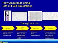
Summary of Values• Dynamic simulation has proven value throughout the wells life cycle– Planning & Design– Start-up– Production optimization / trouble shooting• For Operators– Reduced risk, increased production and reduced down time• For Service Companies– New service offers and value added solutions• For Engineering companies– Extending Flow assurance to include the well and near wellbore– Offering further value to your client base using familiar tools23
e dynamicThank you <strong>for</strong> your attention and…24