

Alcove-Style (Flanged) Bath Module Bodyfit GT-4860 - Aker
Alcove-Style (Flanged) Bath Module Bodyfit GT-4860 - Aker
Alcove-Style (Flanged) Bath Module Bodyfit GT-4860 - Aker

Create successful ePaper yourself
Turn your PDF publications into a flip-book with our unique Google optimized e-Paper software.
GUIDELINES<br />
FOR UNIT<br />
INSTALLATION<br />
These guidelines are recommended by<br />
MAAX <strong>Aker</strong> for the proper installation of<br />
their product. A careful review of these<br />
procedures (and any referenced<br />
publications) before starting is important<br />
in avoiding unnecessary problems<br />
resulting in an improper assembly or<br />
installation.<br />
NOTE: All drawings in this publication<br />
are typical, and may appear different<br />
than the actual items being installed. In<br />
addition, optional items may be shown<br />
on the units which may not have been<br />
ordered on the unit being installed.<br />
ON WHIRLPOOL EQUIPPED MODELS,<br />
A SEPARATE SET OF INSTRUCTIONS<br />
IS PACKED WITH THE UNIT FOR THE<br />
WHIRLPOOL SYSTEM. READ THEM<br />
BEFORE INSTALLING UNIT!<br />
WARNING!<br />
NEVER LIFT OR HANDLE WHIRLPOOL<br />
BY SYSTEM PIPING AT ANY TIME.<br />
LIFTING THE UNIT BY THE PIPING<br />
CAN CAUSE SYSTEM DAMAGE.<br />
Special Notes to Installer<br />
✱ It is the sole responsibility of the<br />
installer to determine, prior to the<br />
installation, the requirements necessary<br />
for compliance with all codes involving<br />
the unit or the installation!<br />
✱ All paperwork packaged with the unit<br />
and any associated options or accessories<br />
should be saved and presented to<br />
the homeowner upon completion of<br />
the installation!<br />
✱ HANDLE THE UNIT BY THE SHELL ONLY!<br />
Never lift any unit by attachments or<br />
piping on the shell.<br />
✱ All published unit dimensions are for<br />
reference only. Any critical dimensions<br />
required for installation should be taken<br />
directly from the unit being installed!<br />
✱ Any independent changes made to<br />
the unit (or options and accessories<br />
supplied with the unit) beyond those<br />
required for normal installation can void<br />
all warranties! (Refer to warranties for<br />
further information.)<br />
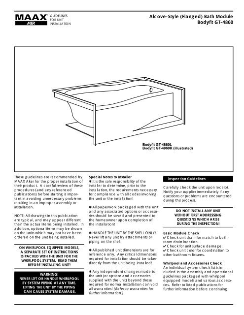
<strong>Alcove</strong>-<strong>Style</strong> (<strong>Flanged</strong>) <strong>Bath</strong> <strong>Module</strong><br />
<strong>Bodyfit</strong> <strong>GT</strong>-<strong>4860</strong><br />
<strong>Bodyfit</strong> <strong>GT</strong>-<strong>4860</strong>L<br />
<strong>Bodyfit</strong> <strong>GT</strong>-<strong>4860</strong>R (illustrated)<br />
Inspection Guidelines<br />
Carefully check the unit upon receipt.<br />
Notify your supplier immediately if any<br />
questions or problems are encountered<br />
during this process.<br />
DO NOT INSTALL ANY UNIT<br />
WITHOUT FIRST ADDRESSING<br />
QUESTIONS WHICH ARISE<br />
DURING THE INSPECTION!<br />
Basic <strong>Module</strong> Check<br />
✔ Check unit drain for match to bathroom<br />
drain location.<br />
✔ Check for unit surface damage.<br />
✔ Check unit color for coordination to<br />
other bathroom fixtures.<br />
Whirlpool and Accessories Check<br />
An individual system check list is included<br />
in the assembly and operational<br />
guidelines packaged with whirlpool<br />
equipped models and various accessories.<br />
Refer to listed publications for<br />
further information before continuing.
GUIDELINES<br />
FOR UNIT<br />
INSTALLATION<br />
Unit Data and Dimensional Guidelines (Tolerance: +0 / -3/8 inch)<br />
49”<br />
15 1/2”<br />
47 1/2”<br />
1 1/2”<br />
1 1/2”<br />
4”<br />
32”<br />
25”<br />
16 1/2”<br />
19 1/2”<br />
7 5/8”<br />
2 1/2” Dia. Overflow<br />
2” Dia. Drain<br />
<strong>Bodyfit</strong> <strong>GT</strong>-<strong>4860</strong>L (shown)<br />
<strong>Bodyfit</strong> <strong>GT</strong>-<strong>4860</strong>R<br />
Unit Sump Bottom Dry Unit Avg. Oper. Max. Sump Base Floor<br />
Model Surface Dim. (W x L) Weight (1) Volume Capacity Area Loading<br />
<strong>Bodyfit</strong> <strong>GT</strong>-<strong>4860</strong> Gelcoat See Special Drawing 135 lb. 49 gal. 98 gal. na na<br />
1. Dry unit weight includes whirlpool system.<br />
Lumbar Support<br />
52 3/8”<br />
60”<br />
25”<br />
43.5”<br />
34.5”<br />
Page 2
GUIDELINES<br />
FOR UNIT<br />
INSTALLATION<br />
Figure 1 - <strong>Alcove</strong> Framing Guidelines<br />
Minimum <strong>Alcove</strong> Depth<br />
Unit Rough-In Depth<br />
49”<br />
15 1/2”<br />
Framing Requirements<br />
10 5/8”<br />
13”<br />
29 1/2”<br />
7 5/8” Drain Center<br />
25" Min.<br />
Wall Height<br />
60”<br />
Due to individual site variations, exact<br />
guidelines for every situation cannot be<br />
supplied. The recommended framing<br />
and dimensional requirements shown<br />
are for a typical application and may<br />
vary, depending on site requirements.<br />
The dimensions shown in Figure 1 are<br />
from the surfaces where the unit will be<br />
attached. This surface can be bare<br />
studding, dry wall or other suitable<br />
underlayment material. It is important<br />
that the floor and all framing be square<br />
and level. Framing should be done<br />
using accepted materials and construction<br />
techniques, in accordance<br />
with all applicable codes.<br />
5"<br />
Drain Cut-Out<br />
47 1/2”<br />
Finished Unit<br />
Depth<br />
<strong>Alcove</strong> Length<br />
Unit Length<br />
21" Wide<br />
Standard<br />
Whirlpool<br />
Pump<br />
Access<br />
Drain Cut-Out<br />
NOTE: Any preconstructed wall may<br />
require modifications or additional<br />
framing members to allow for pipes or<br />
fittings which protrude from the unit on<br />
whirlpool equipped models, for proper<br />
unit installation.<br />
NOTE: A pump access is MANDATORY<br />
for all whirlpool equipped modules.<br />
Additional access areas may be<br />
necessary to comply with code requirements.<br />
(Figure 1)<br />
21" W x 16" H<br />
Pump Access<br />
MANDATORY<br />
for All Whirlpool<br />
Equipped Units<br />
Installation Procedure<br />
Page 3<br />
With the unit positioned in the alcove,<br />
several details must be checked prior to<br />
securing the unit in place.<br />
(Figures 2a & 2b)<br />
✔ Confirm unit apron is resting flush on<br />
the floor.<br />
✔ Confirm drain position.<br />
✔ Confirm the unit is level along each<br />
side and each end.<br />
✔ Confirm the unit is square in the<br />
alcove framework.<br />
ON WHIRLPOOL EQUIPPED UNIT<br />
✔ Check for required modifications to<br />
framing due to whirlpool components.
GUIDELINES<br />
FOR UNIT<br />
INSTALLATION<br />
The unit must also be positioned square<br />
in the alcove framework. The use of<br />
shim or filler material behind the nailing<br />
flange at each framing member may<br />
be required to maintain the unit in the<br />
proper position.<br />
After the unit is confirmed level and<br />
square in the alcove, drill a 1/8 inch<br />
hole through the nailing flange at each<br />
framing member and every 8 inches<br />
along the front nailing flanges. Secure<br />
the unit in place across the back wall<br />
first, followed by the flanges at each<br />
end and along the front flanges, using<br />
1-1/4 inch long (large headed) nails or<br />
other appropriate fasteners. Continuously<br />
check to confirm the unit remains<br />
square within the alcove as it is being<br />
secured. (Figures 3a & 3b)<br />
WARNING!<br />
THE UNIT BOTTOM SHOULD<br />
BE CLEAR OF ALL POTENTIALLY<br />
DAMAGING DEBRIS AND THE SURFACE<br />
PROTECTED BEFORE STEPPING INSIDE.<br />
CAUTION: It is advisable to protect<br />
the unit surface with a thin plywood<br />
or cardboard shield while fastening<br />
the flange to the framing.<br />
Water Supply and Drain Connections<br />
Refer to, and follow, the assembly and<br />
installation instructions provided with<br />
the supply valves and drain system.<br />
Carefully check all fittings and connections<br />
for leaks.<br />
Figure 2a - Unit<br />
Installation<br />
Procedure<br />
Nailing<br />
Flange<br />
Figure 2b - Unit<br />
Installation<br />
Procedure<br />
Nailing<br />
Flange<br />
2. Level Tub<br />
in Framed Area<br />
Figure 3a - Securing Unit<br />
Drill 1/8 inch hole through<br />
flange at each framing member.<br />
Nailing Flange<br />
Wall Framing<br />
Wall<br />
Framing<br />
Confirm unit apron is<br />
resting flush on floor. 1. Position Tub<br />
in Framed Area<br />
Wall<br />
Framing<br />
Confirm the tub is level<br />
along the sides and<br />
across each end.<br />
Confirm Drain Alignment<br />
Confirm unit is square<br />
in framed area.<br />
Figure 3b - Securing Unit<br />
Secure unit to<br />
framing with<br />
large headed<br />
fasteners.<br />
Wall<br />
Framing<br />
CAUTION: Protect unit surface<br />
with a shield when fastening.<br />
Page 4<br />
Wall Framing<br />
Wall Framing<br />
Nailing Flange
Figure 4 - Wall Finishing<br />
Furring Strip or<br />
Shim Material<br />
Wall Framing<br />
GUIDELINES<br />
FOR UNIT<br />
INSTALLATION<br />
Water Resistant<br />
Underlayment<br />
Waterproof<br />
Sealant<br />
Nailing<br />
Flange<br />
Finishing Guidelines<br />
Furring strips or filler material may be<br />
required over the framing to ensure the<br />
underlayment will lie flush over the<br />
nailing flanges. A water resistant<br />
underlayment is recommended on<br />
areas surrounding the unit. Stop the<br />
underlayment 1/16 to 1/8 inch from the<br />
unit surface, and fill the space with a<br />
continuous bead of waterproof sealant.<br />
Carefully fasten the underlayment near<br />
the unit to avoid damaging the unit<br />
surface. Seal the seams and edges of<br />
the underlayment, as required, and<br />
install the finish material to specifications.<br />
(Figure 4)<br />
Unit Surface Care<br />
WARNING!<br />
NEVER USE ABRASIVE MATERIALS,<br />
NOR ABRASIVE CLEANERS<br />
ON THE UNIT SURFACE!<br />
EXTREME CAUTION is urged regarding<br />
the use of any cleaner, acid or solvent<br />
on the unit surface.<br />
READ, AND FOLLOW ALL PACKAGE<br />
LABELS AND INSTRUCTIONS!<br />
Through routine use, the unit surface<br />
can collect residues from soap, bath<br />
additives and natural body oils. Additional<br />
deposits can also collect from<br />
minerals or particles found in the water.<br />
After each use, wipe the excess water<br />
from the unit. This practice will reduce<br />
the buildup of deposits and help<br />
maintain the natural unit lustre.<br />
Following a thorough surface cleaning,<br />
an application of quality automotive<br />
wax will help reduce major accumulations.<br />
The actual schedule for cleaning,<br />
and waxing, will depend on unit usage<br />
and water quality.<br />
WARNING!<br />
AVOID APPLYING WAX<br />
TO THE UNIT BOTTOM!<br />
◆ Routine Cleaning: Mild, nonabrasive<br />
cleaner specifically formulated for<br />
gelcoat and acrylic surfaces recommended.<br />
(Rinse surface thoroughly.)<br />
◆ Heavy Soap Deposits: Liquid ammonia<br />
household cleaner, applied full<br />
strength. (Rinse surface thoroughly.)<br />
◆ Stubborn Stains: Liquid household<br />
cleaner or hydrogen peroxide, applied<br />
full strength. Place a saturated clean<br />
rag directly on stain and let stand<br />
several hours. (Rinse surface thoroughly.)<br />
For extreme cases, buff area with white<br />
automotive polishing compound until<br />
stain disappears, and apply a quality<br />
automotive wax to surface.<br />
◆ Hard Water Scales: Liquid scale<br />
remover or white vinegar, applied full<br />
strength. (Rinse surface thoroughly.)<br />
Page 5<br />
◆ Mold/Mildew: Liquid mildew remover<br />
or baking soda and water paste. Apply<br />
paste and allow to fizz several minutes.<br />
(Rinse surface thoroughly.)<br />
◆ Construction Adhesive: Soften<br />
adhesive with hand held dryer and peel<br />
off adhesive. (Caution is advised when<br />
using any electrical device near water.)<br />
For stubborn cases, apply rubbing<br />
alcohol or nail polish remover, full<br />
strength, to adhesive. (Rinse surface<br />
thoroughly.)<br />
WARNING!<br />
BATH MATS OR OTHER ITEMS<br />
WHICH ARE HELD IN PLACE USING<br />
SUCTION AGAINST THE UNIT SURFACE<br />
MUST BE REMOVED FROM THE FLOOR<br />
OF THE UNIT AFTER EACH USE.<br />
OVER A PROLONGED PERIOD, FAILURE<br />
TO REMOVE THESE TYPES OF ITEMS<br />
FROM THE BOTTOM OF THE UNIT CAN<br />
RESULT IN SURFACE DAMAGE.
GUIDELINES<br />
FOR UNIT<br />
INSTALLATION<br />
MAAX <strong>Aker</strong> as the manufacturer of<br />
<strong>Bath</strong>, Tub/Shower, Shower and Whirlpool<br />
Equipped <strong>Module</strong>s, reserves the<br />
right without prior notice to:<br />
a. Modify the design and manufacture<br />
of its existing products or product<br />
lines without incurring any obligation<br />
to make like modifications to products<br />
previously manufactured.<br />
b. Add new products, product lines<br />
and/or colors and options.<br />
c. Discontinue existing products,<br />
product lines and/or colors and<br />
options.<br />
Any claims, statements or contracts<br />
made regarding materials, manufacturing<br />
methods, duration and/or obligations<br />
involving MAAX <strong>Aker</strong> other than<br />
those stated in the MAAX <strong>Aker</strong> written<br />
Limited Warranty are disclaimed.<br />
Review the terms and conditions<br />
of the Limited Warranty.<br />
Code compliance for the basic unit<br />
structure and construction is monitored<br />
by recognized groups using accepted<br />
testing and inspection procedures.<br />
ANSI Z 124.1 - 1995<br />
American National Standard<br />
for Plastic <strong>Bath</strong>tub Units<br />
MAAX Marion<br />
4601 Eighth Avenue<br />
Marion, IA 52302<br />
MAAX Martinsburg<br />
718 Mid-Atlantic Parkway<br />
Martinsburg, WV 25401<br />
MAAX Plymouth<br />
2121 Walter Glaub Dr.<br />
Plymouth, IN 46563<br />
MAAX Valdosta<br />
1625 James P. Rodgers Road<br />
Valdosta, GA 31601<br />
GELCOATED FIBERGLASS AND VACUUM<br />
FORMED ACRYLIC LIMITED WARRANTY<br />
MAAX <strong>Aker</strong> extends to the original purchaser and subsequent<br />
consumer a limited warranty on MAAX <strong>Aker</strong> Gelcoated Fiberglass and<br />
Vacuum Formed Acrylic modules (herein called "unit") against defects in<br />
materials and/or workmanship, which results in a significantly altered<br />
appearance or affects the performance of the unit for its intended purpose<br />
during the time period stated from date of purchase.<br />
GELCOATED FIBERGLASS UNIT.....................3 YEAR DURATION<br />
VACUUM FORMED ACRYLIC UNIT...............10 YEAR DURATION<br />
Page 6<br />
During this time period, MAAX <strong>Aker</strong> will, at its discretion (following<br />
inspection and verification of the claimed defect by an authorized company<br />
representative) either repair and/or refinish the unit or supply a replacement<br />
unit of comparable size and color without charge, but excluding any costs<br />
associated with the removal of and/or reinstallation of the unit. All MAAX <strong>Aker</strong><br />
authorized and installed options and accessories are addressed under a<br />
separate warranty coverage program titled: OPTIONS AND ACCESSORIES<br />
LIMITED WARRANTY.<br />
THIS WARRANTY DOES NOT COVER DEFECTS RESULTING FROM:<br />
(a) improper unit installation, the surrounding structure or plumbing connections<br />
beyond the recommendations supplied by MAAX <strong>Aker</strong> within the scope of<br />
applicable codes and ordinances; or<br />
(b) accident, abuse, misuse, negligence, fire, flood, or acts of God; or<br />
(c) unreasonable use, including any use beyond that intended for the unit and/<br />
or failure to follow the Care and Maintenance Instructions for the unit; or<br />
(d) any unauthorized alteration or modification to the unit beyond those<br />
required for normal installation, the addition of auxiliary powered devices or<br />
systems including but not limited to those which generate light, heat, or steam,<br />
or any other deviation to the unit not specifically designed for the unit, nor<br />
authorized in writing or installed by MAAX <strong>Aker</strong>; or<br />
(e) removal of unit from the initial installation site; or<br />
(f) the additions of enclosures, handicap accessories, grab bars, and/or other<br />
appliances and fittings (including installation technique) not specifically<br />
designed for the unit, nor authorized in writing or installed by MAAX <strong>Aker</strong>.<br />
REPAIR, REFINISHING, OR THE SUPPLY OF A REPLACEMENT UNIT UNDER THIS<br />
WARRANTY SHALL BE THE EXCLUSIVE REMEDY. MAAX AKER SHALL NOT BE LIABLE<br />
FOR ANY INCIDENTAL OR CONSEQUENTIAL DAMAGES, INCLUDING ANY DAM-<br />
AGE TO THE BUILDING, ITS CONTENTS OR OCCUPANTS, OR FOR BREACH OF ANY<br />
EXPRESSED OR IMPLIED WARRANTY. ANY IMPLIED WARRANTY REGARDING UNIT<br />
FITNESS FOR A PARTICULAR PURPOSE IS LIMITED IN DURATION TO THE TERMS OF<br />
THIS WARRANTY.<br />
Some states do not allow the exclusion or limitation of incidental or<br />
consequential damages, or allow limitations on the duration of an implied<br />
warranty. Therefore, the above exclusions and/or limitations may not apply.<br />
THIS WARRANTY PROVIDES SPECIFIC LEGAL RIGHTS, WHICH CAN VARY FROM<br />
STATE TO STATE.<br />
Form No.: Y - ATI - 608.02/090103 September, 2003
