Instruction Sheet 660-510 - S&C Electric Company
Instruction Sheet 660-510 - S&C Electric Company
Instruction Sheet 660-510 - S&C Electric Company

You also want an ePaper? Increase the reach of your titles
YUMPU automatically turns print PDFs into web optimized ePapers that Google loves.
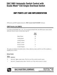
S&C Remote Supervisory Pad-Mounted GearOutdoor Distribution (14.4 kv and 25 kv)ICommunication Processor ModuleFor Communication and ControlEquipment Group1 CONFIGURING THE COMMUNICATION PROCESSOR MODULE - Continued 1step 5The “Configure D20” screen will appear as shown below.Step 6A “Select Application Table” screen will appear, similarP-NeW-!de.tronIc Inc. Configuration System 4.40-Configure D20Select Application Tabla -Using the arrow keys, select Configure Applicationsand press aENTER>.1Three application files of the form -CFGandthree application files of the form Bxxx-CFG will belisted, as shown.Do not select AOOO-CFG, A014_CFG, or any of theBxxx-CFG files. Using the arrow keys, select theremaining Axxx-CFG file-in this instanceAOO9-CFG-and press . (This remainingapplication file is the one used to configure the CPM,and has been specially developed in accordance withthe requirements of your communication protocol.)It is possible that more than three application filesof the form Axxx-CFG have been included on theCPM Application Configuration Files diskette. You’llneed to open all Axxx-CFG files except AOOO-CFGand AO14-CFG to determine which one specifiesthe CPM address, operating parameters of thecommunication channel between the master stationand the CPM, and status point mapping and analogpoint mapping, as discussed in the following steps.If you select the wrong application file, pressasc>.<strong>660</strong>1.5 1 0 INSTRUCTION SHEETPage 4 of 13 S&C ELECTRIC Chicago COMPANYJuly 20,1992 S&C ELECTRIC CANADA 0 TorontoLT
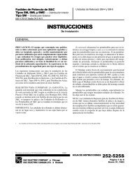
S8C Remote Supervisory Pad-Mounted GearICommunication Processor ModuleOutdoor Distribution (14.4 kv and 25 kv)For Communication and ControlEquipment GroupCONFIGURING THE COMMUNICATION PROCESSOR MODULE - ContinuedStep 9 appropriate value for this installation. In thisChange the program from insert mode to overtype mode the address 20 was changed to 6.(as shown at the bottom of the screen) by pressing. Now change the RTU address to the/* ...................................................................... */DATA-TABLE = 1 /* Port Configuration Table Definition *I/* RTS On Delay = 30 ms/* RTS Off Delay = 12 ms/* Character to character timeout = 30 ms/* Communication port timeout = 60 seconds/* Baud rate = 1200 baud/* Stop bits = 2/* Parity = None/* 1 Logical RTU defined on this COM port/* Offset of 0 into the LRU cross reference table/* Using CPM communication port #1/* ...................................................................... */DATA-TABLE = 2 /* LRU Cross Reference Configuration Table *I61 01 /* RTU address of LRU I Offset into A009-LRU *//* ....................................................................... */A009-CFG. TXT = Overtype = Wrap: OFF line 157 col 9 =Step 10 Now save the change by pressing .Place the program in edit mode (asshown at the bottomof the screen)by simultaneously pressing cA>./* ...................................................................... */DATA-TABLE = 1 /* Port Configuration Table Definition *IRTS On Delay = 30 msRTS Off Delay = 12 msCharacter to character timeout = 30 msCommunication port timeout = 60 secondsBaud rate = 1200 baudStop bits = 2Parity = None1 Logical RTU defined on this COM portOffset of 0 into the LRU cross referenceUsing CPM communication port #1*I*I*I*I*I*I*I*Itable *I*I/* ...................................................................... */DATA-TABLE = 2 /* LRU Cross Reference Configuration Table *I6, 0, /* RTU address of LRU , Offset into A009-LRU */* ....................................................................... */Edit action: save cancel goto find replace block include upload wrapIexample<strong>660</strong>m51 0 INSTRUCTION SHEETPage 6 of 13 S&C ELECTRIC COMPANY ChicagoJuly 20,1992S&C ELECTRIC CANADA LTD. Toronto
CONFIGURING THE COMMUNICATION PROCESSOR MODULE - Continued1step 11You’ll be returned to the “Configure D20” screen.P-NEW-Westronic Inc. Confkquration System 1.10-1parameters are listed in another data table. Access thisdata table by repeating Steps 5 and 6. Using the arrowkeys, scroll through the various tables until you findthe data table with comments relating to communicationparameters. This data table wil be similar tothe one-shown below in “DATA-TAI3LJ3 = 1.”step 12Communication parameters were set at the factory andneed only be accessed to verify that they are corrector to revise the settings from those normally used. TheseI/* ...................................................................... */I*I*I*I*I*I*I*I*I*I*/* Port Configuration Table DefinitionRTS On Delay = 30 msRTS Off Delay = 12 msCharacter to character timeout = 30 msCommunication port timeout = 60 secondsBaud rate = 1200 baudStop bits = 2Parity = None1 Logical RTU defined on this COM portOffset of 0 into the LRU cross reference tableUsing CPM communication port #lI/* ...................................................................... */DATA-TABLE = 2/* LRU Cross Reference Configuration Table6, 0, /* RTU address of LRU , Offset into A009-LRU/* ....................................................................... */A009-CFG.TXT = Insert Wrap: OFF line 157 col 9 =Review the communication parameters. If they areappropriate, press and proceed to Step 13. Ifnot, revise them.To revise a parameter, you’ll once again need to press to change the program from insert modeto overtype mode. Change the parameter as required.Then place the program in edit mode by simultaneouslypressing . Save the change by pressing.*I*I*I*I*I*I*I*I*I*I*I*I*IS&C ELECTRICS&C ELECTRIC CANADAINSTRUCTION SHEET 66@5 1 0Chicago COMPANY Page 7 of 13Toronto LTD.July 20,1992
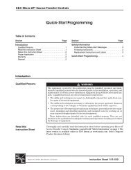
S8C Remote Supervisory Pad-Mounted GearICommunication Processor ModuleOutdoor Distribution (14.4 kv and 25 kv)For Communication and ControlEquipment GroupICONFIGURING THE COMMUNICATION PROCESSOR MODULE - ContinuedStep 13mapping and analog point mapping are listed in otherOnce again you'll be returned to the "Configure D20" data tables. Access these data tables by repeatingscreen.Steps 5 and 6. Using the arrow keys, scroll through thevarious tables until you find the data table with-we.tronic 1°C. Canfiguration sy.t.m 4.40-P-NEWcomments relating to status point mapping. This dataI I table will be to similar the below one"DATA-TABLE = 5."IStep 14Status point mapping and analog point mapping werealso set at the factory and need only be accessed toverlfy their correctness or to revise them. Status point/* ...................................................................... */DATA"llEX,E = 5 /* StatusISOE point mapping *I#O - port 1 """""""""- *I/*"""""""""" mu0,3, 1,3, 2,3, 3,3, 4,3, 513, 613, 7,3, 8,3, 9,3,10,3, 11,3, 12,3, 13,3, 14,3, 15,3, 16,3, 17,3, 18,3, 19,3,20~3, 21,3, 22,3, 23,3, 24,3, 25,3, 26,3, 27,3, 2a,3, 29,3,30~3, 31~3, 32,3, 33,3, 34,3, 35,3, 36,3, 37,3, 3a,3, 39,3,/* ...................................................................... */DATA-TABLE = 6 /* Analog point mapping *I/* """"""""""#o - port 1 ..................... *Imu0,10,00, 1,10,00, 2,10,00, 3,10,00, 4,10,00, 5,10,00,6,10,00, 7,10,00, 8,10,00, 9,10,00, 10,10,00, 11,10,00,12,10,00, 13,10,00, 14,10,00, l!i,lO,OO, 16,10,00, 17,10,00,/* .......................................................................... */A009-CFG.TXT = Insert Wrap: OFF line 207 col = 1Review the status point mapping and revise the You can also review the analog point mapping andmapping if necessary.revise this mapping if necessary in the same manner.T~ revise the mapping, youll Once again need to press This data table will be similar to the one shown above to change the program from insert mode in "DATA-TABLE = 6." If the analog point mapping isto overtype mode. Change the mapping as required. correct press .Then place the program in edit mode by simultaneouslypressing %T> . Save the change by pressing.6665 1 0 INSTRUCTION SHEETPage 8 of 13 S&C ELECTRIC Chicago COMPANYJuly 20,1992 S&C ELECTRIC CANADA TorontoL
~~ ~ ~~1 CONFIGURING THE COMMUNICATION PROCESSOR MODULE - Continued IStep 15Upon completion, you’ll again be“Configure D20” screen.returned to theStep 17When compiling has been completed a screen willappear, similar to the one shown below.Loading data file: AOOO-CFG.TBLI have found 6 tablesLoading data file: A014-CFG.TBLI have found 3 tablesLoading data file: A009-CFG.TBLI have found 9 tablesLoading data file: BOOB-CFG.TBLI have found 2 tablesLoading data file: BOlO-CFG.TBLI have found 3 tablesUsing the arrow keys, select Generate System andpress .Step 16The “Generate System” screen will appear as shownbelow.-w.stronic Inc. configuration Systam 1.40-Generate systemLoading data file: 6011-CFG.TBLI have found 2 tables27984 bytes free in NvRAp(.-- NvRAn file creation completed normally. --Command complete. Press Enter to return to Crosstalk:Press .step 18You’ll be returned to the ”Generate System” screen.P-NEW~--W.stronic Inc. Configuration System 4.40-1Using the arrow keys, select Create NVRAM file andpress . The data files wil be compiled andsaved on the CPM Application Configuration Filesdiskette.Using the arrow keys, select Return to previous menuand press .step 19You’ll again be returned to the “Configure D20” screen.S&C ELECTRIC COMPANY 0 ChicagoS&C ELECTRIC CANADA LTD. TorontoUsing the arrow keys, select Return to Main Menuand press .INSTRUCTION SHEET <strong>660</strong>41 0Page 9 of 13July 20, 1992
SBC Remote Supervisory Pad-Mounted GearOutdoor Distribution (14.4 kv and 25 kv)ICommunication Processor ModuleFor Communication and ControlEquipment Group1 CONFIGURING THE COMMUNICATION PROCESSOR MODULE - ContinuedIstep 20You'll be returned to the "Main Menu" screen.step 22The 'Westronic Incorporated WESDAC D20 SystemLogin" screen wil appear as shown below.IWESTRDNICWESDAC D20 SYSTaWGINENTER USER NAME:Using the arrow keys, select Communications andpress .step 21The "Communications" screen wil appear as shownbelow.-w.stronlc Inc. conflquratlon System 1.40-Type westronic and press . Youll then beasked to enter the password. Type rd and press.Step 23The "Main Menu" screen for the WESDAC D20 Systemwill appear as shown below.IIcouun1c.tion.Go onlin. with D20 WDisconnect from D20-nGo onllne with the 520 PDovnload rileset up communcation portChsnqe Current Phone Book CardReturn to usin MenuSelect wlth f 4, press "1STATUS: NOWL nain Menu D ~ E 01/91 04:46:231. SYSTM DATA DISPLIYS2. SYSTM FTINCI'IONS3. APPLICATION MENUSUsing the arrow keys, select Go online with D2O"and press .Press again. (Pressing the firsttime will result in a prompt "Press F1 to return.") Thecommunication link wil be established between theCPM and the personal computer.Using the arrow keys, select 2. SYSTEM FUNCTIONSand press .<strong>660</strong>.15 1 0 INSTRUCTION SHEETPage of 13 10 SBC ELECTRIC COMPANY ChicagoJuly 20,1992 S&C ELECTRIC CANADA TorontoL
~~ ~~ ~I CONFIGURING THE COMMUNICATION PROCESSOR MODULE - ContinuedIstep 24The "System Function Menu" screen will appear asshown below.Step 26You'll be returned to the "Communications" screen.-w..tronic 1°C. conriquration system 4.40-STATUS: NORMAL sy.t.m ~unctlon nenu D.c 01/91 01:47:2020 n i. onllneD20IP is Offline1. SET TIRE and DATE2. PERIPHERAL STATUS DISPLAY3. D20 MONITOR1. ERROR WUsing the arrow keys, select 3. D20 MONITOR andpress .Step 25The D20 monitor will open and a screen will appear,similar to the one shown below.Using the arrow keys, select Download File and press. The NVRAM file will be downloaded fromthe personal computer to the CPM.Step 27You'll again be returned to thescreen.-w.stronic 1°C. Configuration syste. 4.10-"Communications"communicationsIAt the D20M> prompt, type sp and press .This action will stop the processor, permitting it toaccept the NVRAM file which has been saved on theCPM Application Configuration Files diskette.A second D20M> prompt will appear. At this prompt,type f 200000 300000 00 and press . Thisaction will clear all processor registers. Ignore the errormessage that may appear.A third D20M> prompt will appear. At this prompt,press .Using the arrow keys, select Go online with D20-Mand press .INSTRUCTION SHEET <strong>660</strong>41 0S&C ELECTRICChicago COMPANYPage 11 of 13S&C ELECTRIC CANADA 0 Toronto LTD.July 20, 1992
SCLC Remote Supervisory Pad-Mounted GearOutdoor Distribution (14.4 kv and 25 kv)ICommunication Processor ModuleFor Communication and ControlEquipment GroupI CONFIGURING THE COMMUNICATION PROCESSOR MODULE - ContinuedStep 28The following screen wil appear.I~21820040a002a0000002a00000000~01200010012000003€34eS2222003a8Q0200260002003ec00000000444354595Q453036Q02003eQ002003da000052S2182003c600010000000100000000Q00a00010010000005dd€€~ ~ ~ ~ ~ o o ~ ~ a o o ~ o o ~ ~ ~ o o o o o o o o o o o o o o o o ~ ~ ~ ~ ~ ~ ~ ~ ~ o ~ ~ ~ ~ ~ o oS2182007€60001000000010Q000000001f00010010000003791CS222200a980020077c00OOOOOOOOQOOOQO5757454c434€4d45OO2OOadcOO2OOacaOOOO1b~~~a~ooab6ooo~ooooooo~oooooooooo~6ooo~oo~~oooo~~~~~eS22220077c002Q06€4002007da0020Qa9a4e41444341303030002007b40Q2007ae0000c~S21820079a00120000001200000000000200010010000006a940S2222006€400200260000000000020077c4443545950453~300020072c002007260000c~~~~a~oo~~~oooaooooooo~oooo~ooo~ooaooo~oo~~ooooo~~~~a~ ~ ~ ~ ~ o o ~ ~ o o o ~ o ~ ~ ~ o o o ~ ~ o ~ a a o o ~ o o ~ ~ ~ 4 4 ~ ~~~~a~oo~~eoo~~oooooo~~oooooooooo~~ooo~oo~oooooo~a~~~~ ~ ~ ~S22220019000000000002001c40020Q26044323053455~45430003~€€40000000Q0000b1~~~a~oo~aeooo~ooooooo~~~oooooooooaooo~ooo~ooooo~a~aoS2222OOQOO55534544QOO~3615O7c7OcO3OQOOQQQQOOOOOOOOOOO4OQOOQQ2QOOQOOOOO3€S2222Q0Q1e8Q000030Q0OOOOO2OOOOQOQOQOQOQOQOQOQOQO2O12bOOQOOOOOQOO2OO19O5aS22220003cO000eQ0QQ0OQQOOOOOOOQOQOQOQOQOQOOOQOQOOQ5O5€4e455754595OQOOOQbS22220005a0000000000OOO7c7OcO3Ooo13615OOQOQOOOOOQOQOOQOOOoooooooQooOOO3aS20c2Q007800000000Q00000005bS2142012b0000Q0000000000000000000Q00006d504cS9030000FCRecord error!D2 OM>Press F1 to return.Ignore "Record error!" At the D20M> prompt, typeboot and press .Step 29The following screen will appear.RELEASE: Nov. 1, 1990Power-up Diagnostics:> Boot CODE (U3) - pass> User RAM (U4) - pass> ROOT: Creating Base Processes: Watchdog - pass: Monitor - pass> ROOT: NVRAM test - pass> ROOT: EPROM test - pass"_""_Spawnning Process(es)PID Name GP PR Stack Agr-List Proc-Add Sp-Err Ac-Err3025~~ALSP o ca 640250 0 E27C 0 0302653 WII 0 FE 640200 o 24oca o 03027C2 DNPN 0 50 2000100 0 27302 Q 0302874 DNPL o 50 2000100 0 287AC 0 0302926 BO11 0 50 2000100 Q 2AA3C 0 03029~8 LOG o FE 640200 0 2AE68 Q 0302A8A WIN 0 32 640125 0 2F2C8 0 0Press F1 to return.66&5 1 0 INSTRUCTION SHEETPage 12 of 13 S&C ELECTRIC Chicago COMPANYJuly 20, 1992 S&C ELECTRIC CANADA Toronto LTD.
I CONFIGURING THE COMMUNICATION PROCESSOR MODULE - Continued 1Step 30You'll be returned to the "Communications" screen.Step 32The "Main Menu" screen will appear as shown below.-Westronic Inc. configuration System 4.10-nain ne""communic:stionsConfigure D20Uti1iti.Bs*tllpE"t*r msQuitSelect with 1 1, press -2Using the arrow keys, select Disconnect h m D20-Mand press aNTER>.Step 31The "Communications" screen wil appear as shownbelow.1 anstronic ~nc. Configuration system 4.10-COmmY"iC?.t10"DDisconnect from D20-UGo onlin. with the D20 PDownload Pileset up couuncation portchange Current Phone Book CardR.turo to Wain -nu- Select vith 1 1, prams ."1D20 n is OfflineD2OIP IS OfflineUsing the arrow keys, select Quit and press< =ENTER>.Conaratulations! You're dune! Turn off the DARTRTU and the computer and disconnect the DARTmaintenance cable. If an isolated 120-volt ac sourcewas connected to the battery charger, turn off thebattery charger and disconnect the ac source.For additional information on the CPM, refer toWestronic, Inc. CPM Product Documentation, "Guideto Configuring the CPM" and "Configuration UsersGuide."Using the arrow keys, select Return to Main Menuand press am&>.INSTRUCTION SHEET <strong>660</strong>41 0S&C ELECTRICCOMPANY Chicago Page 13 of 13S&C ELECTRIC CANADA 0 Toronto LTD.July 20,1992

![Boletin Descriptivo 851-30S [Spanish, 3 MB, 12/20/2004]](https://img.yumpu.com/49573007/1/190x245/boletin-descriptivo-851-30s-spanish-3-mb-12-20-2004.jpg?quality=85)

![Boletin de Especificaciones 771-31S [Spanish, 2 MB, 8/30/2010]](https://img.yumpu.com/48742025/1/190x245/boletin-de-especificaciones-771-31s-spanish-2-mb-8-30-2010.jpg?quality=85)