- Page 4 and 5:
TEREXLIFT 51-19MHandler with Telesc
- Page 7 and 8:
1.0 INTRODUCTIONOwners, Users, and
- Page 9 and 10:
SECTION 2SAFETY RULES57.4400.0100 T
- Page 11:
2.0 SAFETY RULES2.1 GENERALMost acc
- Page 14:
• Always follow the instructions
- Page 17 and 18:
3.0 MACHINE REFERENCES3.1 MACHINE P
- Page 19 and 20:
57.4400.0100 TX51-19M-1-SM 01-29-02
- Page 21 and 22:
57.4400.0100 TX51-19M-1-SM 01-29-02
- Page 23 and 24:
3.3 EXPLANATION OF THE DIFFERENTSYM
- Page 25 and 26:
The chassis serial number is stampe
- Page 27 and 28:
3.13 DESCRIPTION OF THE MAINCOMPONE
- Page 29 and 30:
DIESEL ENGINE• Make Perkins• Mo
- Page 31 and 32:
SECTION 4CONTROLS AND INSTRUMENTS57
- Page 33 and 34:
4.0 PREPARATION, INSPECTIONAND ADJU
- Page 35 and 36:
THIS PAGEINTENTIONALLYBLANK57.4400.
- Page 37 and 38:
4.5 CONTROLS AND INSTRUMENTS01. Hyd
- Page 39 and 40:
4.6 CONTROL DESCRIPTION1. Hydraulic
- Page 41 and 42:
6. Air Vents - Allows air flow in t
- Page 43 and 44:
14. Cab Fan - To turn the fan on an
- Page 45:
23. Fuse / Relay Panel - The electr
- Page 48 and 49:
4-8 OPERATING THE CONTROL LEVERThe
- Page 50 and 51:
4-10 Side Shifting The ForksBefore
- Page 52 and 53:
4-12 Quick-Coupling the Fork Attach
- Page 54 and 55:
THIS PAGEINTENTIONALLYBLANK52 TX51-
- Page 56 and 57:
5.3 JUMP-STARTING THE ENGINE8. Rein
- Page 58 and 59:
THIS PAGEINTENTIONALLYBLANK56 TX51-
- Page 60 and 61:
THIS PAGEINTENTIONALLYBLANK58 TX51-
- Page 62 and 63:
6.2 LUBRICANT CHART60 TX51-19M-1-SM
- Page 64 and 65:
THIS PAGEINTENTIONALLYBLANK62 TX51-
- Page 66 and 67:
7.2 ‘A’ MAINTENANCE CHECKS - 50
- Page 68 and 69:
7.4 ‘C’ MAINTENANCE CHECKS - 50
- Page 70 and 71:
7.6 ‘E’ MAINTENANCE CHECKS - 20
- Page 72 and 73:
THIS PAGEINTENTIONALLYBLANK70 TX51-
- Page 74 and 75:
THIS PAGEINTENTIONALLYBLANK72 TX51-
- Page 76 and 77:
8.3 DRAIN ENGINE FUEL PRE-FILTERThe
- Page 78 and 79:
8.10 LUBE CYLINDERSRaise the boom a
- Page 80 and 81:
THIS PAGEINTENTIONALLYBLANK78 TX51-
- Page 82 and 83:
THIS PAGEINTENTIONALLYBLANK80 TX51-
- Page 84 and 85:
9.3 CHECK ENGINE AIR FILTER9.4 CHEC
- Page 86 and 87:
THIS PAGEINTENTIONALLYBLANK84 TX51-
- Page 88 and 89:
THIS PAGEINTENTIONALLYBLANK86 TX51-
- Page 90 and 91:
10.2 CHANGE ENGINE OIL FILTERDiscar
- Page 92 and 93:
10.6 CHANGE HYDRAULICRESERVOIR FILT
- Page 94 and 95:
THIS PAGEINTENTIONALLYBLANK92 TX51-
- Page 96 and 97:
11.4 CHECK ELECTRICALSYSTEMRemove t
- Page 98 and 99:
THIS PAGEINTENTIONALLYBLANK96 TX51-
- Page 100 and 101:
THIS PAGEINTENTIONALLYBLANK98 TX51-
- Page 102 and 103:
THIS PAGEINTENTIONALLYBLANK100 TX51
- Page 104 and 105:
THIS PAGEINTENTIONALLYBLANK102 TX51
- Page 106 and 107:
THIS PAGEINTENTIONALLYBLANK104 TX51
- Page 108 and 109:
THIS PAGEINTENTIONALLYBLANK106 TX51
- Page 110 and 111:
14.2 SLIDER PADS ADJUSTMENTIf the c
- Page 112 and 113:
14.4 ATTACHMENT PLATE REMOVAL /INST
- Page 114 and 115:
6. Use a 17 mm wrench to hold the s
- Page 116 and 117:
4. Make a reference mark at the gea
- Page 118 and 119:
2. Carefully clean the area around
- Page 120 and 121:
9. Using a 13 mm wrench, remove the
- Page 122 and 123:
THIS PAGEINTENTIONALLYBLANK120 TX51
- Page 124 and 125:
THIS PAGEINTENTIONALLYBLANK122 TX51
- Page 126 and 127:
8. Support the boom cylinders with
- Page 128 and 129:
9. Insert the pin holding coupling
- Page 130 and 131:
9. Pull the inner section out appro
- Page 132 and 133:
3. Install the compensation cylinde
- Page 134 and 135:
6. Connect the flexible hoses to th
- Page 136 and 137:
Do not use steel hammer or pinch ba
- Page 138 and 139:
CLEANING AND INSPECTIONPerform the
- Page 140 and 141:
THIS PAGEINTENTIONALLYBLANKDO NOT D
- Page 142 and 143:
11. Tag and disconnect the hoses fr
- Page 144 and 145:
6. Connect large hose (#6) to botto
- Page 146 and 147:
3. Slowly raise the axle until the
- Page 148 and 149:
FRONT AXLEDO NOT DISASSEMBLE ANY CO
- Page 150 and 151:
DO NOT DISASSEMBLE ANY COMPONENT (S
- Page 152 and 153:
DO NOT DISASSEMBLE ANY COMPONENT (S
- Page 154 and 155:
DO NOT DISASSEMBLE ANY COMPONENT (S
- Page 156 and 157:
DO NOT DISASSEMBLE ANY COMPONENT (S
- Page 158 and 159:
DO NOT DISASSEMBLE ANY COMPONENT (S
- Page 160 and 161:
DO NOT DISASSEMBLE ANY COMPONENT (S
- Page 162 and 163:
DO NOT DISASSEMBLE ANY COMPONENT (S
- Page 164 and 165:
DO NOT DISASSEMBLE ANY COMPONENT (S
- Page 166 and 167:
DO NOT DISASSEMBLE ANY COMPONENT (S
- Page 168 and 169:
DO NOT DISASSEMBLE ANY COMPONENT (S
- Page 170 and 171:
DO NOT DISASSEMBLE ANY COMPONENT (S
- Page 172 and 173:
DO NOT DISASSEMBLE ANY COMPONENT (S
- Page 174 and 175:
DO NOT DISASSEMBLE ANY COMPONENT (S
- Page 176 and 177:
DO NOT DISASSEMBLE ANY COMPONENT (S
- Page 178 and 179:
REAR AXLEDO NOT DISASSEMBLE ANY COM
- Page 180 and 181:
DO NOT DISASSEMBLE ANY COMPONENT (S
- Page 182 and 183:
DO NOT DISASSEMBLE ANY COMPONENT (S
- Page 184 and 185:
DO NOT DISASSEMBLE ANY COMPONENT (S
- Page 186 and 187:
DO NOT DISASSEMBLE ANY COMPONENT (S
- Page 188 and 189:
DO NOT DISASSEMBLE ANY COMPONENT (S
- Page 190 and 191:
DO NOT DISASSEMBLE ANY COMPONENT (S
- Page 192 and 193:
DO NOT DISASSEMBLE ANY COMPONENT (S
- Page 194 and 195:
DO NOT DISASSEMBLE ANY COMPONENT (S
- Page 196 and 197:
DO NOT DISASSEMBLE ANY COMPONENT (S
- Page 198 and 199:
DO NOT DISASSEMBLE ANY COMPONENT (S
- Page 200 and 201:
DO NOT DISASSEMBLE ANY COMPONENT (S
- Page 202 and 203:
DO NOT DISASSEMBLE ANY COMPONENT (S
- Page 204 and 205:
THIS PAGEINTENTIONALLYBLANKDO NOT D
- Page 206 and 207:
THIS PAGEINTENTIONALLYBLANKDO NOT D
- Page 208 and 209:
17.2 HYDRAULIC TROUBLESHOOTINGFAULT
- Page 210 and 211:
FORKUP/DOWNSWAYCYLINDERy32x3 4 T P
- Page 212 and 213:
THIS PAGEINTENTIONALLYBLANK210 TX51
- Page 214 and 215:
17.3 ELECTRICAL TROUBLESHOOTING CON
- Page 216 and 217:
17.3 ELECTRICAL TROUBLESHOOTING CON
- Page 218 and 219:
DO NOT DISASSEMBLE ANY COMPONENT (S
- Page 220 and 221:
218 TX51-19M-1-SM 01-29-02 57.4400.
- Page 222 and 223:
THIS PAGEINTENTIONALLYBLANKDO NOT D
- Page 224 and 225:
18.2 CYLINDER HOLDING VALVEREMOVALF
- Page 226 and 227:
RDE 92003-01-R/05.99Hinweis / Inhal
- Page 228 and 229:
SchnittbildSectional viewHWD / EPD
- Page 230 and 231:
RDE 92003-01-R/05.99Allgemeine Repa
- Page 232 and 233:
RDE 92003-01-R/05.99BaugruppenSub a
- Page 234 and 235:
RDE 92003-01-R/05.99Hilfspumpe abdi
- Page 236 and 237:
RDE 92003-01-R/05.99Stellkolbendeck
- Page 238 and 239:
RDE 92003-01-R/05.99Druckabschneidu
- Page 240 and 241:
RDE 92003-01-R/05.99Steuergerät de
- Page 242 and 243:
RDE 92003-01-R/05.99Pumpe demontier
- Page 244 and 245:
RDE 92003-01-R/05.99Triebwerk ausba
- Page 246 and 247:
RDE 92003-01-R/05.99Überprüfungsh
- Page 248 and 249:
RDE 92003-01-R/05.99Kontrolle der T
- Page 250 and 251:
RDE 92003-01-R/05.99Stellkolben, Tr
- Page 252 and 253:
RDE 92003-01-R/05.99Triebwerk einba
- Page 254 and 255:
RDE 92003-01-R/05.99Triebwerk einba
- Page 256 and 257:
RDE 92003-01-R/05.99Reparaturanleit
- Page 258 and 259:
RDE 92003-01-R/05.99Pumpe montieren
- Page 260 and 261:
RDE 92003-01-R/05.99Sicherheitsbest
- Page 262 and 263:
RDE 92003-01-R/05.99Einstellhinweis
- Page 264 and 265:
RDE 92003-01-R/05.99Einstellhinweis
- Page 266 and 267:
RDE 92003-01-R/05.99Einstellhinweis
- Page 268 and 269:
RDE 92003-01-R/05.99Einstellhinweis
- Page 270 and 271:
RDE 91604-01-R/08.96TypschlüsselTy
- Page 272 and 273:
RDE 91604-01-R/08.96Hinweis / Inhal
- Page 274 and 275:
RDE 91604-01-R/08.96SchnittbildSect
- Page 276 and 277:
RDE 91604-01-R/08.96SchnittbildSect
- Page 278 and 279:
RDE 91604-01-R/08.96Dichtsätze und
- Page 280 and 281:
RDE 91604-01-R/08.96Baugruppen / St
- Page 282 and 283:
RDE 91604-01-R/08.96Dichtmutter aus
- Page 284 and 285:
RDE 91604-01-R/08.96Steuerteile abd
- Page 286 and 287:
RDE 91604-01-R/08.96Verstellung abd
- Page 288 and 289:
RDE 91604-01-R/08.96Anschlußplatte
- Page 290 and 291:
RDE 91604-01-R/08.96Stellkolben aus
- Page 292 and 293:
RDE 91604-01-R/08.96Triebwerk ausba
- Page 294 and 295:
RDE 91604-01-R/08.96Triebwerk austa
- Page 296 and 297:
RDE 91604-01-R/08.96Überprüfungsh
- Page 298 and 299:
RDE 91604-01-R/08.96Triebwerk monti
- Page 300 and 301:
RDE 91604-01-R/08.96Triebwerk monti
- Page 302 and 303:
RDE 91604-01-R/08.96Triebwerk monti
- Page 304 and 305:
RDE 91604-01-R/08.96Anschlußplatte
- Page 306 and 307:
RDE 91604-01-R/08.96Anziehdrehmomen
- Page 308 and 309:
RDE 91604-01-R/08.96Sicherheitsbest
- Page 310 and 311:
DO NOT DISASSEMBLE ANY COMPONENT (S
- Page 312 and 313:
RE 90302-02-B/05.94A4V/DA-A6V/ DA I
- Page 314 and 315:
RE 90302-02-B/05.94A4V/DA-A6V/ DA I
- Page 316 and 317:
RE 90302-02-B/05.94A4V/DA-A6V/ HA I
- Page 318 and 319:
RE 90302-02-B/05.94A4V/DA-A6V/ DA C
- Page 320 and 321:
RE 90302-02-B/05.94A4V/DA-A6V/ DA I
- Page 322 and 323:
RE 90302-02-B/05.94A4V/DA-A6V/ DA I
- Page 324 and 325:
RE 90302-02-B/05.94A4V/DA-A6V/Fault
- Page 326 and 327:
DO NOT DISASSEMBLE ANY COMPONENT (S
- Page 328 and 329:
THIS PAGEINTENTIONALLYBLANKDO NOT D
- Page 330 and 331:
8. Use a screwdriver or a 7 mm wren
- Page 332 and 333:
THIS PAGEINTENTIONALLYBLANKDO NOT D
- Page 334 and 335:
700 SeriesPerkins 700 SeriesUser's
- Page 336 and 337:
700 SeriesContents1 General informa
- Page 338 and 339:
Section 1General information700 Ser
- Page 340 and 341:
Section 1General information700 Ser
- Page 342 and 343:
Section 2Engine Views700 SeriesEngi
- Page 344 and 345:
Section 2Engine Views700 SeriesFron
- Page 346 and 347:
Section 3Operation Instructions700
- Page 348 and 349:
Section 3Operation Instructions700
- Page 350 and 351:
Section 4Preventive Maintenance700
- Page 352 and 353:
Section 4Preventive Maintenance700
- Page 354 and 355:
Section 4Preventive Maintenance700
- Page 356 and 357:
Section 4Preventive Maintenance700
- Page 358 and 359:
Section 4Preventive Maintenance700
- Page 360 and 361:
Section 4Preventive Maintenance700
- Page 362 and 363:
Section 4Preventive Maintenance700
- Page 364 and 365:
Section 4Preventive Maintenance700
- Page 366 and 367:
Section 5Engine Fluids700 SeriesFue
- Page 368 and 369:
Section 5Engine Fluids700 SeriesCoo
- Page 370 and 371:
Section 6Fault Diagnosis700 SeriesL
- Page 372 and 373:
Section 7Engine Preservation700 Ser
- Page 374 and 375:
Section 8Parts and Service700 Serie
- Page 376 and 377: DO NOT DISASSEMBLE ANY COMPONENT (S
- Page 378 and 379: 700 SeriesFOREWORDThis manual is il
- Page 380 and 381: 700 SeriesContentsTitle page …
- Page 382 and 383: 700 Series16 Cylinder block assembl
- Page 384 and 385: Section 10General Information700 Se
- Page 386 and 387: Section 10General Information700 Se
- Page 388 and 389: Section 10General Information700 Se
- Page 390 and 391: Section 10General Information700 Se
- Page 392 and 393: Section 10General Information700 Se
- Page 394 and 395: Section 11Specifications700 SeriesO
- Page 396 and 397: Section 11Specifications700 SeriesD
- Page 398 and 399: Section 11Specifications700 SeriesU
- Page 400 and 401: Section 11Specifications700 SeriesD
- Page 402 and 403: Section 11Specifications700 SeriesD
- Page 404 and 405: Section 11Specifications700 SeriesT
- Page 406 and 407: Section 11Specifications700 SeriesP
- Page 408 and 409: Section 11Specifications700 SeriesF
- Page 410 and 411: Section 12Cylinder Head Assembly700
- Page 412 and 413: Section 12Cylinder Head Assembly700
- Page 414 and 415: Section 12Cylinder Head Assembly700
- Page 416 and 417: Section 12Cylinder Head Assembly700
- Page 418 and 419: Section 12Cylinder Head Assembly700
- Page 420 and 421: Section 12Cylinder Head Assembly700
- Page 422 and 423: Section 12Cylinder Head Assembly700
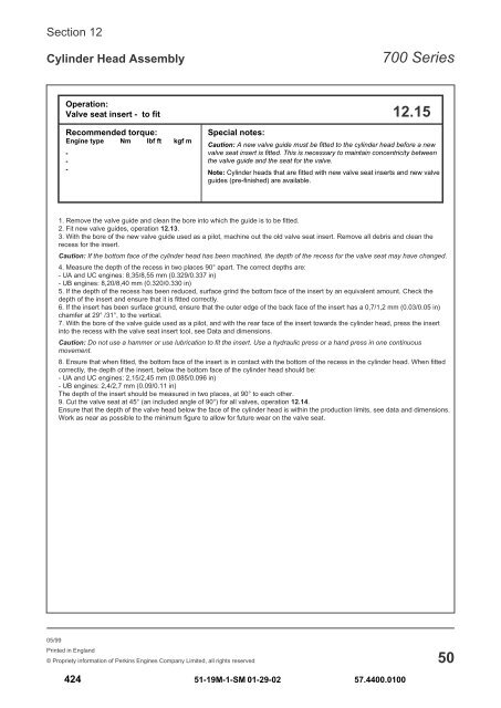
- Page 424 and 425: Section 12Cylinder Head Assembly700
- Page 428 and 429: Section 13Connecting Rod Assembly70
- Page 430 and 431: TOPPTOPPSection 13Connecting Rod As
- Page 432 and 433: Section 13Connecting Rod Assembly70
- Page 434 and 435: Section 13Connecting Rod Assembly70
- Page 436 and 437: Section 13Connecting Rod Assembly70
- Page 438 and 439: Section 13Connecting Rod Assembly70
- Page 440 and 441: Section 14Crankshaft Assembly700 Se
- Page 442 and 443: Section 14Crankshaft Assembly700 Se
- Page 444 and 445: Section 14Crankshaft Assembly700 Se
- Page 446 and 447: Section 14Crankshaft Assembly700 Se
- Page 448 and 449: Section 14Crankshaft Assembly700 Se
- Page 450 and 451: Section 14Crankshaft Assembly700 Se
- Page 452 and 453: Section 14Crankshaft Assembly700 Se
- Page 454 and 455: Section 15Timing Case and Drive Ass
- Page 456 and 457: Section 15Timing Case and Drive Ass
- Page 458 and 459: Section 15Timing Case and Drive Ass
- Page 460 and 461: Section 15Timing Case and Drive Ass
- Page 462 and 463: Section 15Timing Case and Drive Ass
- Page 464 and 465: Section 15Timing Case and Drive Ass
- Page 466 and 467: Section 15Timing Case and Drive Ass
- Page 468 and 469: Section 16Cylinder Block Assembly70
- Page 470 and 471: Section 17Engine Timing700 SeriesOp
- Page 472 and 473: Section 17Engine Timing700 SeriesOp
- Page 474 and 475: Section 17Engine Timing700 SeriesOp
- Page 476 and 477:
Section 18Turbocharger700 SeriesOpe
- Page 478 and 479:
Section 18Turbocharger700 SeriesOpe
- Page 480 and 481:
Section 19Lubrication System700 Ser
- Page 482 and 483:
Section 19Lubrication System700 Ser
- Page 484 and 485:
Section 19Lubrication System700 Ser
- Page 486 and 487:
Section 19Lubrication System700 Ser
- Page 488 and 489:
Section 20Fuel System700 SeriesOper
- Page 490 and 491:
Section 20Fuel System700 SeriesOper
- Page 492 and 493:
Section 20Fuel System700 SeriesOper
- Page 494 and 495:
Section 20Fuel System700 SeriesOper
- Page 496 and 497:
Section 20Fuel System700 SeriesOper
- Page 498 and 499:
Section 20Fuel System700 SeriesOper
- Page 500 and 501:
Section 20Fuel System700 SeriesOper
- Page 502 and 503:
Section 20Fuel System700 SeriesOper
- Page 504 and 505:
Section 20Fuel System700 SeriesOper
- Page 506 and 507:
Section 20Fuel System700 SeriesOper
- Page 508 and 509:
Section 20Fuel System700 SeriesOper
- Page 510 and 511:
Section 21Cooling System700 SeriesO
- Page 512 and 513:
Section 21Cooling System700 SeriesO
- Page 514 and 515:
Section 21Cooling System700 SeriesO
- Page 516 and 517:
Section 22Flywheel and Flywheel Hou
- Page 518 and 519:
Section 22Flywheel and Flywheel Hou
- Page 520 and 521:
Section 23Electrical Equipment700 S
- Page 522 and 523:
Section 23Electrical Equipment700 S
- Page 524 and 525:
Section 23Electrical Equipment700 S
- Page 526 and 527:
Section 24Auxiliary Equipment700 Se
- Page 528 and 529:
Section 25Special Tools700 SeriesOp
- Page 530 and 531:
Section 25Special Tools700 SeriesOp
- Page 532 and 533:
THIS PAGEINTENTIONALLYBLANKDO NOT D
- Page 534 and 535:
DO NOT DISASSEMBLE ANY COMPONENT (S
- Page 536 and 537:
DO NOT DISASSEMBLE ANY COMPONENT (S
- Page 538 and 539:
DO NOT DISASSEMBLE ANY COMPONENT (S
- Page 540 and 541:
Where Used&OEM NameSPECIAL TOOLS LI
- Page 542 and 543:
Where Used&OEM NameSPECIAL TOOLS LI
- Page 544 and 545:
SPECIAL TOOLS LISTTX51-19M Light Ca
- Page 546:
SPECIAL TOOLS LISTTX51-19M Light Ca