
You also want an ePaper? Increase the reach of your titles
YUMPU automatically turns print PDFs into web optimized ePapers that Google loves.
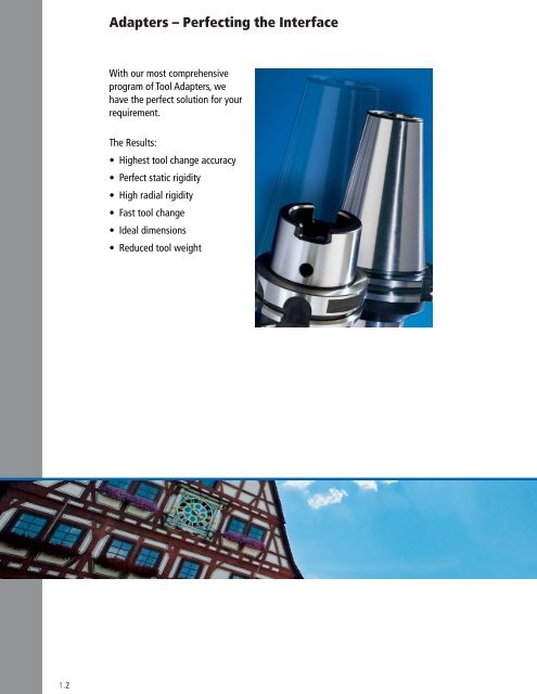
<strong>Adapter</strong>s – Perfecting the InterfaceWith our most comprehensiveprogram of Tool <strong>Adapter</strong>s, wehave the perfect solution for yourrequirement.The Results:• Highest tool change accuracy• Perfect static rigidity• High radial rigidity• Fast tool change• Ideal dimensions• Reduced tool weight1.2
<strong>Adapter</strong>s1Page<strong>Adapter</strong> Program OverviewTaper Shank HoldersFlange <strong>Adapter</strong>s1.4 – 1.51.6 – 1.231.24 – 1.35HSK <strong>Adapter</strong>sABS ® <strong>Adapter</strong>Clamping Units for TurningThermal Expansion System1.36 – 1.451.46 – 1.841.851.86 – 1.95Easy Special TM <strong>Adapter</strong>s <strong>Chapter</strong> 51.3
<strong>Adapter</strong> Program OverviewTaper Shank HolderTaper Shank HolderTaper Shank HolderHSK <strong>Adapter</strong>CATMORI-SEIKINMTBwith ABS ® 1.8–1.9with ABS ® 1.9with ABS ® 1.11<strong>Adapter</strong> with ABS ® 1.38for Coolant Glandswith ABS ® 1.8for Coolant Glandswith ABS ® 1.17for Coolant Glandswith ABS ® 1.11Eccentric <strong>Adapter</strong>with ABS ® 1.38Eccentric Holderwith ABS ® 1.12Precision Tool HolderFWD1.39BTDIN 69871 AD/BCoolant Inducer 1.13with ABS ®with ABS ® 1.10with ABS ® 1.12Hydraulic Chuck 1.40–1.41Integral Drill Holder 1.14for Coolant Glandswith ABS ® 1.10Collet Holder SZV 1.42Flange <strong>Adapter</strong>Integral Micro-Adj.Boring Head1.15Eccentric Holder 1.12with ABS ®Spindle <strong>Adapter</strong> Flange1.26Tapping Chuck GWF 1.43Integral Mill DrillChuck1.16–1.17Coolant Inducerwith ABS1.13<strong>Adapter</strong> Flangewith KomLoc ® System1.28–1.31CAT - HSK <strong>Adapter</strong> 1.44Integral Precision ToolHolder1.18Integral Drill Holderwith ABS ®1.14Built-in Flangewith KomLoc ® System1.32–1.35Integral Collet Holder 1.19Integral HydraulicChuck1.20–1.231.4
<strong>Adapter</strong> Program Overview<strong>Adapter</strong> ABS ® Tool Holder ABS ® N Clamping Unitfor Turning ToolSymbol1NC-VDI Clamping Unit 1.48–1.49Precision Tool HolderFWD1.60–1.61Straight Shank BoringBar Clamping Unit1.85Machine ConnectionExampleCATBTNMTBHSK-AISO12164-1ABS ®Clamping Unit 1.50–1.53End Mill HolderEMH / HWD1.62–1.63Balancing NoteExamplePre-balancedQ6.38,000 RPMEccentric Adj. Holder 1.54with ABS ®Morse Taper HolderHMK1.64Thermal ExpansionSystemCoolant SupplyExampleCentral/RingTC Round Shank<strong>Adapter</strong>1.55Tapping Chuck HolderGWF1.65–1.69HSK-A ThermalExpansion Chuck1.88Total RunoutExample 5 µmLightweightMicro-adjustable DrillHolder with ABS ® 1.56Collet HolderSZV1.70–1.79CAT ThermalExpansion Chuck1.89–1.90Rotating Tool / WorkpieceExampleABS ® Reducer 1.57Hydraulic Chuck 1.80–1.83BT ThermalExpansion Chuck1.91Vibration DampeningTorsion BendingABS ® Extension 1.58Short Mill Drill ChuckKMDC / NCB1.84ABS ® ThermalExpansion Chuck1.92AdjustableRadially AxiallyABS ® LightweightExtensionABS ® LightweightReducer1.591.59Easy Special<strong>Adapter</strong><strong>Chapter</strong> 5KomLoc ® HSK Clamping SystemExampleSystem SystemK MTool ConnectionExampleDIN1835-EWhistle NotchDIN1835-BWeldonCylindricalShankDIN6535HE+ DIN6595HSK-AISO12164-1ABS ®1.5
Taper Shank HoldersCATwith ABS ® ConnectionPage1.8 – 1.9for Coolant Glands · with ABS ® Connection1.8Eccentric Holder with ABS ® Connection1.12with ABS ® Connection / Coolant Inducer1.13Integral MV Micro-adjustable Drill Holder with ABS ® Connection1.14Integral Drill Holder with Straight Shank Connection1.14Integral Micro-Adjustable Boring Head1.15Integral Mill Drill Chuck1.16Integral Precision Tool Holder1.18Integral Collet Holder1.19Integral Hydraulic Clamping Chuck1.20 – 1.231.6
Taper Shank HoldersBTwith ABS ® ConnectionPage1.101for Coolant Glands · with ABS ® Connection1.10Eccentric Holder with ABS ®1.12with ABS ® Connection / Coolant Inducer1.13Integral MV Micro-adjustable Drill Holder with ABS ® Connection1.14MORI-SEIKIwith ABS ® Connection1.9Integral Mill Drill Chuck1.17NMTBwith ABS ® Connection1.11for Coolant Glands · with ABS ® Connection1.11DIN 69871 AD/Bwith ABS ® Connection1.121.7
CATMachineConnectionCoolant SupplyCentralRotatingToolToolConnectionMachineConnectionCoolant SupplyCentral / RingRotatingToolToolConnectionCATABS ®CATABS ®Taper Shank Holderwith ABS ® Connectionfor through spindle coolantTaper Shank Holderwith ABS ® Connectionfor use with KRD / KRSD Coolant GlandsLL1Position of tool point(single point tool)LNPTL1Position of tool point(single point tool)ABSdd1ABSdCoolant Ring(see <strong>Chapter</strong> 8)ABS ®ABS ®CAT Description Order No.ABSd L L1CAT Description Order No.CoolantABSringd d1 L L1 NPT404550ABS 25CAT40 A52 10120 25 2.362 1.612 2.00ABS 32CAT40 A52 10130 32 2.362 1.612 2.20ABS 40CAT40 A52 10140 40 2.362 1.612 2.45ABS 50CAT40 A52 10150 50 2.953 2.203 2.75ABS 50CAT40 EXT A52 10180 50 5.512 4.762ABS 63CAT40 A52 10160 63 3.543 2.793 3.50ABS 25CAT45 A52 10220 25 2.362 1.612 3.30ABS 32CAT45 A52 10230 32 2.362 1.612 3.55ABS 40CAT45 A52 10240 40 2.362 1.612 4.40ABS 50CAT45 A52 10250 50 2.362 1.612 5.10ABS 63CAT45 A52 10260 63 3.346 2.596 6.20ABS 80CAT45 A52 10270 80 3.937 3.187ABS 25CAT50 A52 10320 25 2.362 1.612 3.20ABS 32CAT50 A52 10330 32 2.362 1.612 6.20ABS 40CAT50 A52 10340 40 2.362 1.612 6.40ABS 50CAT50 A52 10350 50 2.362 1.612 7.05ABS 50CAT50 EXT A52 10400 50 6.299 5.549ABS 63CAT50 A52 10360 63 3.150 2.400 7.70ABS 80CAT50 A52 10370 80 3.937 3.187 10.00ABS 100CAT50 A52 10380 100 4.921 4.171 15.00ABS 125CAT50 A52 10390 125 5.709 4.959 23.50ABS 63CAT60 A52 10460 63 3.150 2.400 16.7060ABS 80CAT60 A52 10470 80 3.150 2.400 22.00ABS 100CAT60 A52 10480 100 3.937 3.187 31.00ABS 125CAT60 A52 10490 125 5.512 4.762 33.00Delivery:Taper shank holders supplied without retention knob.Plug screw, ABS ® Replacement parts see <strong>Chapter</strong> 8.404550ABS 40CAT40KR A52 10640 40 40 3.740 0.913 1/8 3.30ABS 50CAT40KR A52 10650 50 50 3.740 0.906 1/8 3.55ABS 63CAT40KR A52 10660 63 70 4.330 1.437 1/8 4.10ABS 40CAT45KR A52 10740 40 40 3.937 1.110 1/8 5.50ABS 50CAT45KR A52 10750 50 50 3.937 1.102 1/8 5.95ABS 63CAT45KR A52 10760 63 70 4.134 1.280 1/8 7.90ABS 40CAT50KR A52 10840 40 40 3.937 1.110 1/8 7.50ABS 50CAT50KR A52 10850 50 50 3.937 1.102 1/8 8.80ABS 63CAT50KR A52 10860 63 70 4.331 1.476 1/8 10.80ABS 80CAT50KR A52 10870 80 80 4.331 1.476 1/8 11.65ABS100CAT50KR A52 10880 100 100 5.118 2.244 3/8 15.00Delivery:Taper shank holders supplied without retention knob andcoolant ring.Plug screw, ABS ® Replacement parts see <strong>Chapter</strong> 8.1.8
CAT AD/BMachineConnectionCoolant SupplyCentral / Drive CollarRotatingToolToolConnectionMORI SEIKIMachineConnectionCoolant SupplyDrive CollarRotatingToolToolConnection1CATAD/BABS ®NMORISEIKIABS ®Taper Shank Holderwith ABS ® -NConnectionTaper Shank Holderwith ABS ® ConnectionLL1Position of tool point(single point tool)LL1Position of tool point(single point tool)ABS-NdABSdABS ® NABS ®CAT Description Order No.ABS-Nd L L1MORI SEIKIDescriptionOrder No.ABSd L L14050ABS 50N-CAT40 AD/B A52 51150 50 2.953 2.203 2.75ABS 63N-CAT40 AD/B A52 51160 63 3.543 2.793 3.50ABS 50N-CAT50 AD/B A52 51350 50 2.362 1.612 7.05ABS 63N-CAT50 AD/B A52 51360 63 3.150 2.400 7.70ABS 80N-CAT50 AD/B A52 51370 80 3.937 3.187 10.00Delivery:Taper shank holders complete without retention knob.Plug screw, ABS ® Replacement parts see <strong>Chapter</strong> 8.4050ABS 25CAT40MS A52 50120 25 2.362 1.612ABS 32CAT40MS A52 50130 32 2.362 1.612ABS 40CAT40MS A52 50140 40 2.362 1.612ABS 50CAT40MS A52 50150 50 2.953 2.203ABS 63CAT40MS A52 50160 63 3.543 2.793ABS 32CAT50MS A52 50330 32 2.362 1.612ABS 40CAT50MS A52 50340 40 2.362 1.612ABS 50CAT50MS A52 50350 50 2.362 1.612ABS 63CAT50MS A52 50360 63 3.150 2.400ABS 80CAT50MS A52 50370 80 3.937 3.187ABS 100CAT50MS A52 50380 100 4.921 4.171Delivery:Taper shank holders complete without retention knob.Plug screw, ABS ® Replacement parts see <strong>Chapter</strong> 8.1.9
BTMachineConnectionCoolant SupplyCentralRotatingToolToolConnectionMachineConnectionCoolant SupplyCentral / RingRotatingToolToolConnectionBTABS ®BTABS ®Taper Shank Holderwith ABS ® Connectionfor through spindle coolantTaper Shank Holderwith ABS ® Connectionfor use with KRD / KRSD Coolant GlandsLL1Position of tool point(single point tool)L2LGL1Position of tool point(single point tool)ABSdd1ABSd1*Plug screwNote: With internal coolant supply, the plug screw shouldbe removed from the coolant hole.1*If necessary replace with sealing screw/seal.ABS ®Short VersionCoolant Ring(see <strong>Chapter</strong> 8)ABS ®BT Description Order No.ABSd L L1BT Description Order No.CoolantABSringd d1 L L1 G30354050ABS 25 BT30 A55 00060 25 1.575 0.552ABS 32 BT30 A55 00070 32 1.969 0.945ABS 40 BT30 A55 00080 40 1.969 1.023ABS 40 BT35 A55 00040 40 1.969 1.024 3.0ABS 50 BT35 A55 00050 50 2.165 1.220 3.1ABS 25 BT40 A55 00120 25 2.362 0.984 2.40ABS 32 BT40 A55 00130 32 2.362 1.299 2.49ABS 40 BT40 A55 00140 40 2.362 1.299 2.67ABS 50 BT40 A55 00150 50 2.362 1.299 2.84ABS 63 BT40 A55 00160 63 2.756 1.693 3.70ABS 32 BT50 A55 00330 32 2.756 0.945 8.29ABS 40 BT50 A55 00340 40 2.756 0.945 8.51ABS 50 BT50 A55 00350 50 2.756 0.945 8.97ABS 63 BT50 A55 00360 63 3.150 1.457 9.55ABS 80 BT50 A55 00370 80 3.937 2.441 11.95ABS100 BT50 A55 00380 100 4.331 2.835 15.10Delivery:Taper shank holders complete with plug screw less retentionknob.Plug screw, ABS ® Replacement parts see <strong>Chapter</strong> 8.4050ABS 40BT40KR A55 00640 40 40 3.543 1.307 M10 3.50ABS 50BT40KR A55 00650 50 50 3.543 1.299 M10 3.50Long VersionABS 50BT50KR A55 10850 50 50 4.134 0.945 M10 10.00ABS 63BT50KR A55 10860 63 70 4.528 1.319 M10 12.50ABS 80BT50KR A55 10870 80 80 4.724 1.516 M10 14.00ABS ®BT Description Order No.40CoolantABSringd d1 L L1 L2ABS 40BT40KR A55 10640 40 40 4.134 1.299 1.575 3.97ABS 50BT40KR A55 10650 50 50 4.134 1.299 1.575 4.52Delivery:Taper shank holders supplied without retention knob andcoolant ring.Plug screw, ABS ® Replacement parts see <strong>Chapter</strong> 8.1.10
NMTBMachineConnectionCoolant SupplyCentralRotatingToolToolConnectionMachineConnectionCoolant SupplyCentral / RingRotatingToolToolConnection1NMTBABS ®NMTBABS ®Taper Shank Holderwith ABS ® Connectionfor through spindle coolantTaper Shank Holderwith ABS ® Connectionfor use with KRD / KRSD Coolant GlandsLL1Position of tool point(single point tool)LNPTL1Position of tool point(single point tool)ABSdd1ABSdCoolant Ring(see <strong>Chapter</strong> 8)ABS ®ABS ®NMTBDescriptionOrder No.ABSd L L1NMTBDescriptionOrder No.CoolantABSringd d1 L L1 NPT4050ABS 40NMTB40 A71 50140 40 1.969 1.067 2.5ABS 50NMTB40 A71 50150 50 1.969 1.146 2.5ABS 63NMTB40 A71 50160 63 3.150 2.327 4.5ABS 40NMTB50 A71 50340 40 2.362 0.945 7.5ABS 50NMTB50 A71 50350 50 2.362 0.945 7.5ABS 63NMTB50 A71 50360 63 2.756 1.339 8.5ABS 80NMTB50 A71 50370 80 3.150 2.555 10.0Delivery:Taper shank holders supplied without retention knob.Plug screw, ABS ® Replacement parts see <strong>Chapter</strong> 8.50ABS 50NMTB50KR A71 50850 50 50 3.740 1.024 1/8 9.0ABS 63NMTB50KR A71 50860 63 70 4.134 1.398 1/8 10.5ABS 80NMTB50KR A71 50870 80 80 4.331 1.594 1/8 12.0Delivery:Taper shank holders supplied without retention knob andcoolant ring.Plug screw, ABS ® Replacement parts see <strong>Chapter</strong> 8.1.11
DIN 69871 AD/BCAT / BTMachineConnectionBalancing Note(<strong>Chapter</strong> 9)Coolant SupplyCentral / Drive CollarRotatingToolToolConnectionMachineConnectionCoolant SupplyDrive CollarAdjustableRotatingToolToolConnectionDIN69871AD/BPre-balancedQ6.38,000 RPMABS ®CAT /BTABS ®Taper Shank Holderwith ABS ® ConnectionEccentric-Taper Shank Holderwith ABS ® ConnectionLL1Position of tool point(single point tool)Adjustment range± 0.010“ on diameterLPosition of tool point(single point tool)ABSdABSdABS ®ABS ®ISO Description Order No.ABSd L L1CAT / BTDescriptionOrder No.ABSdL4050ISOABS 50 ISO40-AD/B A50 55150 50 1.969 1.181 2.43ABS 63 ISO40-AD/B A50 55160 63 3.543 2.756 4.52ABS 40 ISO50-AD/B A50 55340 40 2.362 0.787 7.28ABS 50 ISO50-AD/B A50 55350 50 2.362 0.866 7.28ABS 63 ISO50-AD/B A50 55360 63 2.362 1.142 7.43ABS 80 ISO50-AD/B A50 55370 80 2.756 1.969 8.62ABS 100 ISO50-AD/B A50 55380 100 4.528 3.740 12.61ABS 125 ISO50-AD/B A50 55390 125 5.709 4.921Delivery:Taper shank in version B complete with change kit, sealscrew and seal ring less retention knob.Balancing Note:Tool Holders or adapters, such as the one show above, are suppliedas a balanced unit. No allowance has been made for itemsused with the unit such as boring tools, milling cutters, inserts,and etc.When used at high speeds, we recommend a precision balancingof entire assembly prior to use.Change kitOrder No.Replacement PartsSeal screwOrder No.Seal ringOrder No.40 L02 30920 5504100810 569410081150 L02 30940 5504101215 5694101215CAT 40 ABS 50 CAT 40 AD/B EH A52 11151 50 2.953CAT 40 ABS 63 CAT 40 AD/B EH A52 11160 63 3.543CAT 50 ABS 50 CAT 50 AD/B EH A52 11351 50 2.362CAT 50 ABS 63 CAT 50 AD/B EH A52 11360 63 3.150BT 40 ABS 50 BT 40 AD/B EH A55 56150 50 2.362 2.82BT 50 ABS 50 BT 50 AD/B EH A55 56350 50 2.756 8.69Delivery:Eccentric taper shank drill holder complete without retentionknob.Note:Additional ABS ® sizes and machine connections areavailable upon request.CAT / BTAdjustment KeyOrder No.Replacement PartsChange KitOrder No.CAT 40 1804300028CAT 50 1804300028BT 40 1804300028 L02 30920BT 50 1804300028 L02 309401.12
CAT / BTMachineConnectionCoolant SupplyInducerRotatingToolToolConnection1CAT /BTABS ®Taper Shank Holderwith ABS ® ConnectionLd2Adjustable0° - 360°dd1SET LENGTH(Adjustable)ASSTOP BLOCKSTROKE.24" .09Jd3ABS ®CAT / BTDescriptionOrder No.ABSd L A d1 d2 d3 S JCAT 40 ABS 50 CI/CAT 40 A52 20550 50 5.512 0 2.551 3.86 1.38 2.56 0.590 12.50CAT 50 ABS 50 CI/CAT 50 A52 20950 50 5.512 0 2.551 3.86 1.38 3.15 0.590 17.00CAT 50 ABS 63 CI/CAT 50 A52 20960 63 5.709 0 2.551 3.86 1.38 3.15 0.787 17.10BT 40 ABS 50 CI/BT 40 A55 10550 50 5.709 0.24 2.551 3.86 1.38 2.56 0.511 12.50BT 50 ABS 50 CI/BT 50 A55 10950 50 6.102 0.59 2.551 3.86 1.38 3.15 0.551 19.30BT 50 ABS 63 CI/BT 50 A55 10960 63 6.299 0.59 2.551 3.86 1.38 3.15 0.748 19.10Delivery:Taper shank holder complete with coolant reducer, less stopblock, mounting hardware and retention knob.Note:Coolant must be filtered.For stop block dimensions and mounting information,see <strong>Chapter</strong> 8.• Improved hole making with better chip control.• Faster feeds and speeds.• Longer tool life.• Up to 5000 RPM and maximum 285 PSI coolant pressure• Enables deep hole operations.• Suitable for use with carbide drills for improvedproductivity.• Provides better control of work piece tolerance due toreduced heat.1.13
CAT / BTMachineConnectionCoolant SupplyCentralAdjustableRotatingToolToolConnectionMachineConnectionCoolant SupplyCentral / RingRotatingToolToolConnectionCAT /BTABS ®CATStraightShankIntegral Drill Holderfor ABS ® ConnectionIntegral Drill Holderfor Straight Shank ConnectionLLL1EABSdd1d*Coolant RingImportant!KUB IT HD Drills used with these holders must be cut off atnotch on shank!ABS ®CAT / BTDescriptionOrder No.ABSd d1 L ECAT Description Order No. d1 L L1CAT 40 CAT 40MV-ABS 50 M01 06030 50 2.756 3.622 0.059CAT 50 CAT 50MV-ABS 50 M01 06040 50 2.756 3.622 0.059BT 40 BT 40MV-ABS 50 M01 06110 50 2.756 3.622 0.059Delivery:Integral drill holder complete without retention knob.ABS ® Replacement parts see <strong>Chapter</strong> 8.Note:The ABS ® seal cannot be fitted into the M01 MicroAdjustable Holder50 ZWH 1.250 CAT 50 A05 00310 1.250 4.913 3.075 9.050 ZWH 1.500 CAT 50 A05 00320 1.500 4.913 3.159 10.1Delivery:Integral drill holder complete without retention knob.Note:Other shank sizes are available on request.* Please use the coolant ring KRD 60 (L0100021)on page 8.41Accurate adjustment with micro-adjustable spindle• Maximum adjustment range .125" on diameter• Scale divisions .001" on diameter• Rigid clamping of head after adjust ment achieved by means of 4clam ping screws on face1.14
CATMachineConnectionCoolant SupplyCentralAdjustableRotatingToolToolConnection1CATABS ®Integral Micro-adjustable Boring Head M020(KFK)radial adjustment of 0.0001“ (0.002mm) per graduation ondiameter, using vernier scaleLL1Ø 0.019“ - 0.079“ 4.61(Ø 0.5mm - 2.0mm)Ø 0.118“ - 0.354“ 4.61(Ø 3.0mm - 9.0mm)Ø 0.220“ - 0.472“ 4.62(Ø 5.6mm - 12.0mm)Ø 0.220“/ 0.272“ 4.70(Ø 5.6mm - 6.9mm)d2ABSd1Ø 0.354“/ 0.433“ 4.70(Ø 5.6mm - 6.9mm) 4.60Ø 0.512“ - 0.669“ 4.70(Ø 13.0mm - 17.0mm)Ø 0.315“ - 1.102“ 4.64(Ø 8.0mm - 28.0mm)Ø 0.469“ - 1.181“ 4.68(Ø 11.9mm - 30.0mm)Ø 1.102“ - 1.732“ 4.96(Ø 28.0mm - 44.0mm)Ø 1.496“ - 4.055“ 4.27(Ø 38.0mm - 103.0mm) 4.26CAT Description Order No.ABSd1d2AdjustmentLL140 CAT 40 KFK1-Z-ABS 32 M02 07200 32 2.692 0.157 3.740 0.63550 CAT 50 KFK1-Z-ABS 32 M02 07210 32 2.756 0.157 3.740 0.635Delivery:Integral micro-adjustable boring head complete withoutretention knob.ABS ® Replacement parts see <strong>Chapter</strong> 8.The micro-adjustable head balanced in zero positionBoring Range:D min= DD max= D1(2×S)1.15
CATMachineConnectionCoolant SupplyCentralRotatingToolToolConnectionCATStraightShankIntegral Mill Drill ChuckCATd1L1L(...) = mmCAT Description Order No. L d1 d2 L14050KMDC 0.5-13 CAT40 A34 60010 4.331 (110) 0.020-0.512 (0.5-13) 1.949 (49.5) 1.142 (29) 4.5KMDC 3-16 CAT40 A34 60020 4.331 (110) 0.118-0.630 (3-16) 2.047 (52) 1.142 (29) 4.7KMDC 0.5-13 CAT50 A34 60050 4.331 (110) 0.020-0.512 (0.5-13) 1.949 (49.5) 1.142 (29) 9.1KMDC 3-16 CAT50 A34 60060 4.331 (110) 0.118-0.630 (3-16) 2.047 (52) 1.142 (29) 9.2KMDC 12-20 CAT 50 A34 60070 4.567 (110) 0.472-0.787 (12-20) 2.480 (63) 1.575 (40) 10.3Delivery:Integral mill drill chuck complete with hex socket wrench,interchangeable seals and seal changing tool less retention knob.1.16
CAT MSMachineConnectionCoolant SupplyCentral / Drive CollarRotatingToolToolConnection1CATMSStraightShankIntegral Mill Drill ChuckCAT MSd1 d2L1L(...) = mmCAT MSDescription Order No. L d1 d2 L140 KMDC 3-16 CAT 40 MS A34 60080 4.331 (110) 0.118-0.630 (3-16) 2.047 (52) 1.142 (29) 4.750 KMDC 3-16 CAT 50 MS A34 60090 4.331 (110) 0.118-0.630 (3-16) 2.047 (52) 1.142 (29) 9.2Delivery:Integral mill drill chuck complete with hex socket wrench,interchangeable seals and seal changing tool less retention knob.1.17
CATMachineConnectionCoolant SupplyCentralRotatingToolToolConnectionCATStraightShankIntegral FWD Precision Tool Holderfor Straight Shank Connection(Metric)L10 d1d2L1All dimensions are in mmReplacement PartsClamping ScrewAdjusting ScrewCAT Description Order No. d1 d2 L L1Order No.Order No.4050CAT 40 FWD 10MM A25 56820 10 28 50 40 N00 70310 N00 71130CAT 40 FWD 12MM A25 56830 12 42 50 45 N00 70370 N00 71230CAT 40 FWD 14MM A25 56840 14 42 50 45 N00 70370 N00 71320CAT 40 FWD 16MM A25 56850 16 48 63 48 N00 70400 N00 71410CAT 40 FWD 18MM A25 56860 18 48 63 48 N00 70400 N00 71410CAT 40 FWD 20MM A25 56870 20 52 63 50 N00 70450 N00 71500CAT 40 FWD 25MM A25 56880 25 52 90 56 N00 70450 N00 71500CAT 50 FWD 10MM A25 66820 10 28 63 40 N00 70310 N00 71130CAT 50 FWD 12MM A25 66830 12 42 63 45 N00 70370 N00 71230CAT 50 FWD 14MM A25 66840 14 42 63 45 N00 70370 N00 71320CAT 50 FWD 16MM A25 66850 16 48 63 48 N00 70400 N00 71410CAT 50 FWD 18MM A25 66860 18 48 63 48 N00 70400 N00 71410CAT 50 FWD 20MM A25 66870 20 52 63 50 N00 70450 N00 71500CAT 50 FWD 25MM A25 66880 25 52 80 56 N00 70450 N00 71500Delivery:Integral precision tool holder complete with clamping andadjusting screws, less hex socket type wrench and retentionknob.• Total Runout 0.01 mm.• A 2° tilted clamping screw secures tool from being pulledout of the chuck.• Central coolant supply through Adjusting Screw.• Length axially adjustable.1.18
CATMachineConnectionCoolant SupplyCentralRotatingToolAdjustableToolConnection1CATCylindricalShankIntegral Collet HolderExternally Adjustable - SZVLVd1Adjusting screw*Dimension “L“ depends on clamping range of colletCAT Description Order No. d1 L* VReplacement PartsCollet nut Spanner wrench Max.collet nutclampingDescription Order No. Description Order No.torque(ft-lbs)40 CAT 40 SZV/ER 32 A05 80350 1.969 3.500 0.402 KC/ER 32 5280601032 E 32 L05 02050 12050 CAT 50 SZV/ER 32 A05 80450 1.969 3.500 0.472 KC/ER 32 5280601032 E 32 L05 02050 120Delivery:Integral collet holder complete with collet nut, shortadjusting screw with hole, less collet, spanner wrench andretention knob.Note:Please see pages 1.72 - 1.79 for the selection of collets,collet nuts and seal disks• For clamping tools with cylindrical shank up to 3/4”(20mm) diameter• Concentricity between taper and tool shank 0.0006“(0.015mm)• Axial adjustment via side adjustable rack and pinionsystem without removal of tool1.19
CATMachineConnectionCoolant SupplyCentralRotatingToolToolConnectionCATStraightShankIntegral Hydraulic Clamping Chuck(Inch)10L1d1d2LReplacement PartsAdjusting ScrewCAT Description Order No. d1 d2 L L1DescriptionOrder No.4050CAT40 .250 A25 56710 .250 1.752 2.520 1.457 FWD M6X1X16 N00 71050CAT40 .375 A25 56720 .375 1.752 2.520 1.673 FWD M10X1X18 N00 71230CAT40 .500 A25 56730 .500 1.752 2.520 1.870 FWD M10X1X18 N00 71230CAT40 .625 A25 56740 .625 1.752 2.520 2.067 FWD M10X1X18 N00 71230CAT40 .750 A25 56750 .750 1.752 2.520 2.067 FWD M10X1X18 N00 71230CAT50 .250 A25 66710 .250 2.752 3.189 1.457CAT50 .375 A25 66720 .375 2.752 3.189 1.673CAT50 .500 A25 66730 .500 2.752 3.189 1.870CAT50 .625 A25 66740 .625 2.752 3.189 1.870CAT50 .750 A25 66750 .750 2.752 3.189 2.067CAT50 1.000 A25 66760 1.000 2.752 3.189 2.402CAT50 1.250 A25 66770 1.250 2.752 3.189 2.559Delivery:Integral hydraulic clamping chuck complete with adjustingscrew, less hex socket type wrench and retention knob.• Total Runout < 0.0002”• Completely enclosed pressure system, sealed against dirtand coolant• Central coolant supply through Adjusting Screw• Length axially adjustable1.20
Reducer Bushingfor Hydraulic Clamping Chucks1L1L2d1 d d2with flange grooves for peripheral coolantReducer Bushing (Inch)Order No. d d1 d2 L1 L2L01 13400 .250L01 13410 .312L01 13420 .375L01 13430 .437L01 13440 .500L01 13450 .625.750 .980 2.00 0.78Gauge PinCylindrical BrushOrder No.d1Order No.d1L00 00080 6L00 00090 8L00 00100 10L00 00110 12L00 00130 16L00 00070 20L00 00160 324779116206 64779116208 84779116210 104779116212 124779116216 164779116220 204779116232 321.21
CATMachineConnectionCoolant SupplyCentralRotatingToolToolConnectionCATStraightShankIntegral Hydraulic Clamping Chuck(Metric)10L1d1d2LAll dimensions are in mmReplacement PartsAdjusting ScrewCAT Description Order No. d1 d2 L L1DescriptionOrder No.4050CAT40 10 mm A25 56620 10 44.5 64 42.5 FWD M6X1X16 N00 71050CAT40 12 mm A25 56630 12 44.5 64 47.5 FWD M10X1X18 N00 71230CAT40 14 mm A25 56640 14 44.5 64 47.5 FWD M10X1X18 N00 71230CAT40 16 mm A25 56650 16 44.5 64 52.0 FWD M10X1X18 N00 71230CAT40 20 mm A25 56670 20 44.5 64 52.5 FWD M10X1X18 N00 71230CAT50 10 mm A25 66620 10 69.9 64 42.5CAT50 12 mm A25 66630 12 69.9 64 47.5CAT50 14 mm A25 66640 14 69.9 64 47.5CAT50 16 mm A25 66650 16 69.9 64 52.5CAT50 20 mm A25 66670 20 69.9 64 52.5CAT50 25 mm A25 66680 25 69.9 64 61.0CAT50 32 mm A25 66690 32 69.9 64 65.0Delivery:Integral hydraulic clamping chuck complete with adjustingscrew, less hex socket type wrench and retention knob.• Total Runout 0.005 mm• Completely enclosed pressure system, sealed against dirtand coolant• Central coolant supply through Adjusting Screw• Length axially adjustable1.22
Reducer Bushingfor Hydraulic Clamping Chucks1L1L2d1 d d2with flange grooves for peripheral coolantReducer Bushing (Metric)All dimensions are in mmOrder No. d d1 d2 L1 L2L01 13290 3L01 13300 4L01 13310 5L01 13320 6L01 13330 8L01 13260 3L01 13270 4L01 13280 5L01 13200 6L01 13210 8L01 13220 10L01 13230 12L01 13240 14L01 13250 16L01 13500 6L01 13510 8L01 13520 10L01 13530 12L01 13540 14L01 13550 16L01 13560 18L01 13570 20L01 13580 2512 19 45 2 0.2220 29 50.5 2 0.2232 39 60.5 3 0.66Gauge PinCylindrical BrushOrder No.d1Order No.d1L00 00080 6L00 00090 8L00 00100 10L00 00110 12L00 00130 16L00 00070 20L00 00160 324779116206 64779116208 84779116210 104779116212 124779116216 164779116220 204779116232 321.23
1.24
Flange <strong>Adapter</strong>sSpindle <strong>Adapter</strong> FlangeABS ® VFS · with ABS ® ConnectionPage1.261HSK <strong>Adapter</strong> Flange with KomLoc ® Clamping System<strong>Adapter</strong> FlangeHSK-RVFHSK-RVFW, Adjustable1.28 – 1.31Built-in FlangeHSK-REFHSK-REFW, Adjustable1.32– 1.35KomLoc ® HSK-Clamping SystemDetail information for KomLoc ® HSK-Clamping System is available on <strong>Chapter</strong> 8.1.25
Spindle Flange <strong>Adapter</strong>MachineConnectionCoolant SupplyCentralRotatingToolToolConnectionSpindleDIN2079ABS ®with ABS ® ConnectionThis adapter flange does not have key slots.Drive keys on spindle head must be removedSpindle head to DIN 2079d2ABSdd1d3L1LISO Description Order No.ABSd d1 d2 d3 L L1304050ABS32 VFS30 A01 01130 320.945 2.51ABS40 VFS30 A01 01140 40 1.102 2.732.756 2.749 3.5430.433ABS50 VFS30 A01 01150 50 1.260 3.13ABS63 VFS30 A01 01160 63 1.575 3.77ABS40 VFS40 A01 01240 401.102 4.45ABS50 VFS40 A01 01250 50 3.150 3.499 4.331 1.260 0.472 4.74ABS63 VFS40 A01 01260 63 1.575 5.73ABS80 VFS40 A01 01270 80 3.937 3.499 4.331 1.732 0.472 6.04ABS50 VFS50 A01 01450 501.260 10.08ABS63 VFS50 A01 01460 63 1.575 11.514.724 5.062 5.9060.669ABS80 VFS50 A01 01470 80 1.732 12.46ABS100 VFS50 A01 01480 100 2.205 14.38ABS125 VFS50 A01 01490 125 5.512 5.062 6.299 2.835 0.669 20.37Delivery:Spindle adapter flange complete.1.26
KomLoc ® HSK-Clamping SystemFeatures of the new system• Simple and low cost spindle contour• Minimum number of extremely sturdy components• Maximum clamping force• Specially designed for high speed machining (HSC)• Internal coolant supply• Practical ejector function1ApplicationsThere are numerous occasions that require manual clamping of hollow tapershank (HSK) tools. The new KOMET HSK clamping system is used throughouttransfer lines, machining centers, turning lathes, multi-head machines andpre-setting devices.• Direct mounting on multi-head machines and short boring spindles• Spindle mounted and location adapter flanges are available• <strong>Adapter</strong>s for extension and reductionUsing the KomLoc ® HSK-Clamping SystemOperation of the KomLoc ® clamping system is quite simple by the turn ofa hexagonal key. A low draw-in moment automatically produces a sturdyand effective clamping action. In addition, an axial movement or turning ofthe locking ring prevents dirt and chips from penetrating into the clampingmechanism.HSC (High Speed Cutting) AbilityThe new KomLoc ® clamping system is predestined to be utilized at highcutting speeds due to the radial expanding effect of the clamping action. Theclamping cartridge is designed to be completely symmetrical in rotation.Coolant supplyInternal coolant supply is introduced by two coolant hoses which form acage with the ejector and the distributor. This cage is supported on floatingbearings and produces a seal for a coolant pressure of p > 30psiApplication detailsThe clamping adapter ensures a excellent transmission of the bending andtorsion moments by maintaining the correct draw-in moments and clampingforces. The direction of these moments is not affected by the position ofclamping cartridge.1.27
HSK-RVF <strong>Adapter</strong> FlangeMachineConnectionCoolant SupplyCentralRotatingToolAdjustableKomLoc ®HSK-ClampingToolConnectionToolConnectionMachineSpindleSystemKHSK-AISO12164-1HSK-CISO12164-1KomLoc ® HSK-Clamping System KRadially adjustable on the machine spindle with adjusting screwLL1L24×90°d1d2HSKdReplacement PartsAccessoriesKomLocClampingSeal ring,shiftingClamping screwDIN 912Description Order No.HSKd d1 d2 L L1 L2deviceOrder No. Order No. Description Order No.HSK-40 RVF A08 51031 40HSK-50 RVF A08 61031 50HSK-63 RVF A08 71031 63HSK-80 RVF A08 81030 80HSK-100 RVF A08 91030 1002.756(70)3.150(80)3.937(100)4.606(117)5.512(140)1.378(35)1.575(40)1.969(50)2.362(60)3.150(80)1.669(42.4)2.087(53)2.559(65)3.339(84.8)4.173(106)1.28(32.5)1.693(43.0)2.087(53.0)2.866(72.8)3.701(94)0.827(21)1.024(26)1.260(32)1.772(45)1.969(50)Delivery:<strong>Adapter</strong> flange complete with KomLoc ® clamping device and locking ring.Please order clamping screw separately.(..) = mm1.15 L07 01040 L07 01440 M6x20-12.9 55011 060202.14 L07 01050 L07 01450 M6x20-12.9 55011 060204.06 L07 01060 L07 01460 M8x25-12.9 55011 080257.98 L07 01070 L07 01470 M8x35-12.9 55011 0803515.66 L07 01080 L07 01480 M10x45-12.9 55011 10045Note:Please use the wiper to clean the taperand the contact face1.28
Connection dimensions for HSK-RVF <strong>Adapter</strong> Flange1L3Section A-Ad8L4AØ d6 × T +0.5022.5°AW145°30°1R 0.25L1L5R 0.4R z2.5Ø d4Ø d9Ø d3Ø d2 F8Ø d1d7R z6.3Ø d5±0.1W2O-RingNBR700.015 A10°AL60.0020.002NOT CONVEXAL2x 5:1Access hole formanual clamping(..) = mmforFlange <strong>Adapter</strong> d1 d2 d3 d4 d5 d6 d7 d8 d9 L1 L2 L3 L4 L5 L6 T W1 W2O-RingA08 51031A08 61031A08 71031A08 81030A08 910302.756(70)3.150(80)3.937(100)4.606(117)5.512(140)1.378(35)1.575(40)1.969(50)2.362(60)3.150(80)1.122(28.5)1.201(30.5)1.516(38.5)1.870(47.5)2.559(65)1.417(36)1.614(41)2.008(51)2.402(61)3.189(81)2.087(53)2.480(63)3.110(79)3.780(96)4.685(119).197(5).197(5).197(5).236(6).236(6)M6 M8X1 .197(5.0)M6 M8X1 .236(6.0)M8 M10X1 .315(8.0)M8 M10X1 .402(10.2)M10 M10X1 .472(12).406(10.3).406(10.3).484(12.3).484(12.3).484(12.3).488(12.4).524(13.3).634(16.1).634(16.1).634(16.1).327(8.3).327(8.3).406(10.3).406(10.3).406(10.3).276(7.0).276(7.0).315(8.0).315(8.0).315(8.0).551(14).551(14).591(15).709(18).787(20).709(18).709(18).787(20).866(22)1.024(26).138(3.5).138(3.5).138(3.5).177(4.5).177(4.5)0° 4X90° 28X30° 4X90° 30X40° 4X90° 38X50° 4X90° 47X522.5° 8X45° 65X5KOMET Drawing No. : N49 134701.29
HSK-RVFW <strong>Adapter</strong> Flange - AdjustableMachineConnectionCoolant SupplyCentralRotatingToolAdjustableAdjustableKomLoc ®HSK-ClampingToolConnectionMachineSpindleSystemKHSK-AISO12164-1KomLoc ® HSK-Clamping System KRadially adjustable on the machine spindle with adjusting screwFine adjustment in face run-out by adjusting screw in adapter flangeLL1L24×90°d1d2HSKdReplacement PartsAccessoriesKomLocClampingSeal ring,shiftingDisc ThreadedPinClamping screwDIN 912Description Order No.HSKd d1 d2 L L1 L2deviceOrder No. Order No. Order No. Order No. Description Order No.HSK-40 RVFW A08 52030 40HSK-63 RVFW A08 72030 63HSK-80 RVFW A08 82030 802.756 1.378 1.669 1.28 0.8271.15 L07 01040(70) (35) (42.4) (32.5) (21)L07 01440 L02 30960 N00 70250 M6x20-12.9 55011060203.937 1.969 2.559 2.087 1.2604.06 L07 01060(100) (50) (65) (53.0) (32)L07 01460 L02 30960 N00 70320 M8x25-12.9 55011080254.606 2.362 3.339 2.866 1.7727.98 L07 01070(117) (60) (84.8) (72.8) (45)L07 01470 L02 30960 N00 70330 M8x35-12.9 5501108035Delivery:<strong>Adapter</strong> flange complete with KomLoc ® clamping device, locking ring, discand threaded pin. Please order clamping screw separately.(..) = mmNote:Please use the wiper to clean the taperand the contact face1.30
Connection dimensions for HSK-RVFW <strong>Adapter</strong> Flange1L3Section A-Ad8L4AØ d6 × T +0.5022.5°AW145°30°1R 0.25L1L5R 0.4R z2.5Ø d4Ø d910°Ø d3Ø d2 F8R z6.3Ø d5±0.1Ø d1d7W2O-RingNBR700.015 AAL60.0020.002NOT CONVEXAL2x 5:1Access hole formanual clamping(..) = mmforFlange <strong>Adapter</strong> d1 d2 d3 d4 d5 d6 d7 d8 d9 L1 L2 L3 L4 L5 L6 T W1 W2O-RingA08 520302.756 1.378 1.122 1.417(70) (35) (28.5) (36)A08 720303.937 1.969 1.516 2.008(100) (50) (38.5) (51)A08 820304.606 2.362 1.870 2.402(117) (60) (47.5) (61)KOMET Drawing No. : N49 134702.087(53)3.110(79)3.780(96).197(5).197(5).236(6)M6 M8X1 .197(5.0)M8 M10X1 .315(8.0)M8 M10X1 .402(10.2).406(10.3).484(12.3).484(12.3).488(12.4).634(16.1).634(16.1).327(8.3).406(10.3).406(10.3).276(7.0).315(8.0).315(8.0).630(16).591(15).709(18).787(20).787(20).866(22).138(3.5).138(3.5).177(4.5)0° 4X90° 28X30° 4X90° 38X50° 4X90° 47X51.31
HSK-REF Built-in FlangeMachineConnectionCoolant SupplyCentralRotatingToolAdjustableKomLoc ®HSK-ClampingToolConnectionShort SpindleDIN69002SystemKHSK-AISO12164-1KomLoc ® HSK-Clamping System KRadially adjustable on the machine spindle with adjusting screwL1d1dd2(..) = mmReplacement PartsAccessoriesKomLocClampingSeal ring,turningBall pressurescrewClamping screwDIN 912Description Order No.HSKd d1 d2 L1deviceOrder No. Order No. Order No. Description Order No.HSK-50 REF A08 61060 50HSK-63 REF A08 71060 63HSK-80 REF A08 81060 80HSK-100 REF A08 91060 1001.654(42)2.165(55)2.677(68)3.465(88)2.724(69.2)3.465(88)4.331(110)5.394(137).689(17.5).886(22.5)1.083(27.5)1.181(30)Delivery:Built-in flange complete with KomLoc ® clamping device and locking ring.Please order clamping screw separately1.19 L07 01050 L07 01761 N10 30739 M5x20-12.9 55011050202.47 L07 01060 L07 01771 N10 30740 M6x30-12.9 55011060304.83 L07 01070 L07 01780 N10 30741 M8x35-12.9 55011080359.04 L07 01080 L07 01790 N10 30742 M10x1x40-12.9 5501110042Note:Please use the wiper to clean the taperand the contact face1.32
Connection dimensions for HSK-REF Built-in Flange1Ø d3+0.1+0.05Ø d4Ø d5d7R z2.5Section A-AL9 +0.30L1 +0.30d8L70.002NOT CONVEX0.03 AAAAOptional with Helicoilthreaded insertR30°6×60°R z6.3120°L5×30°Ø d2 +0.15+0.1Ø d6±0.1Ø d1L10R z6.345°L8A4×90°L4L6×15°L2±0.04L3 +1 0Position of access hole forclamping system(..) = mmforBuilt-in <strong>Adapter</strong> d1 d2 d3 +0.5 d4 d5 d6 d7 d8 L1 L2 L3 L4 L5 L6 L7 L8 L9 L10 RA08 610602.480 1.654 1.299 1.024(63) (42) (33) (26)A08 710603.150 2.165 1.673 1.339(80) (55) (42.5) (34)A08 810603.937 2.677 2.079 1.654(100) (68) (52.8) (42)A08 910604.921 3.465 2.598 2.087(125) (88) (66) (53)KOMET Drawing No. : N49 13460.394(10).630(16).630(16).787(20)2.047(52)M5 M52.598(66)M6 M63.228(82)M8 M84.173(106) M10X1 M8 1.354(34.4).591 .974 1.398(15) (24.75) (35.5).705 1.195 1.673(17.9) (30.35) (42.5).957 1.583 2.256(24.3) (40.2) (57.3)2.142 2.992(54.4) (76).118(3).138(3.5).157(4).177(4.5).059(1.5).059(1.5).079(2).079(2).039(1).039(1).059(1.5).079(2).197(5).236(6).315(8).315(8).472(12).630(16).709(18).984(25).724(18.4).941(23.9)1.295(32.9)1.669(42.4).610(15.5).787(20).976(24.8)1.236(31.4).098(2.5).118(3).138(3.5).177(4.5)1.33
HSK-REFW Built-in Flange - AdjustableMachineConnectionCoolant SupplyCentralRotatingToolAdjustableAdjustableKomLoc ®HSK-ClampingToolConnectionShort SpindleDIN69002SystemKHSK-AISO12164-1KomLoc ® HSK-Clamping System KRadially adjustable on the machine spindle with adjusting screwFine adjustment in face run-out by adjusting screw in adapter flangeL1d1dd2Replacement PartsAccessoriesKomLocClampingSeal ring,turningBall pressurescrewDisc ThreadedPinClampingscrewHSKdeviceDIN 912Description Order No. d d1 d2 L1 Order No. Order No. Order No. Order No. Order No. Order No.DescriptionHSK-40 REFW A08 72060 1002.165 4.331 .9453.84 L07 01060 L07 01780 N10 30741 L02 30960 N00 70270 5501108035(55) (110) (24)(M8X35-12.9)Delivery:Built-in flange complete with KomLoc ® clamping device, locking ring,disc and threaded pin. Please order clamping screw separately.(..) = mmNote:Please use the wiper to clean the taperand the contact face1.34
Connection dimensions for HSK-REFW Built-in Flange1Ø d3+0.1+0.05Ø d4Ø d5120°Ø d2 +0.15+0.1Ø d6±0.1d7Ø d1R z2.5Section A-AL9 +0.30L1 +0.30L70.002NOT CONVEX0.03 AAOptional with Helicoilthreaded insertd8AAR30°107°6×60°L5×30°L10R z6.3R z6.3d9×T45°L8A4×90°L4L6×15°L2±0.04L3 +1 0Position of access hole forclamping system(..) = mmforBuilt-in <strong>Adapter</strong> d1 d2 d3 +0.5 d4 d5 d6 d7 d8 d9 L1 L2 L3 L4 L5 L6 L7 L8 L9 L10 R TA08 720603.937(100)2.165(55)1.673(42.5)1.339(34).630(16)3.110(79)M8M60.217(5.5).650(16.5).742 1.614(28.85) (41).138(3.5).059(1.5).039(1).236(6).984(25).882(22.4).787(20).118(3).394(10)KOMET Drawing No. : N49 134601.35
HSK <strong>Adapter</strong>• The modern connection between the machine spindle and the cuttingtool is the HSK (Hollow Shank) system• The HSK is standardized per ISO 12164• The main feature of the HSK connection is the taper and face contact.• HSK provides following essential advantages:Highest tool changing accuracy, high static rigidity, highradial rigidity, compatible with high-speed machines, shortertool change times.• The version HSK-A is used with automatic tool changers with machiningcenters, turn/mill centers and other cutting tool machines.• HSK-A can also be used on machines with manual tool change.• KOMET is offering the additional HSK versions on request(see <strong>Chapter</strong> 8).1.36
HSK <strong>Adapter</strong><strong>Adapter</strong>with ABS ® / ABS ® N ConnectionEccentric <strong>Adapter</strong>with ABS ® ConnectionPrecision Tool HolderHSK-A FWDPage1.381.381.391Hydraulic ChuckCollet HolderHSK-A SZVTapping ChuckHSK-A GWF1.40 – 1.411.421.43HSK with integrated KomLoc ® HSK-Clamping SystemCAT - HSK <strong>Adapter</strong>1.441.37
HSK-AMachineConnectionHSK-AISO12164-1Balancing Note(<strong>Chapter</strong> 9)Pre-balancedQ6.310,000 RPMCoolant SupplyCentral<strong>Adapter</strong>with ABS ® ConnectionRotatingToolRotatingWorkpieceToolConnectionMachineConnectionCoolant SupplyCentralRotatingToolRotatingWorkpieceAdjustableToolConnectionHSK-AABS ® ISOABS ®12164-1LL1LL1HSKdABSd1HSKdABSd1Total adjustment± 0.0098“ (0.25 mm)on the diameter* for Fine boring application only (..) = mmABS ®ABS ®(..) = mmDescriptionOrder No.HSK ABSd d1 L L1DescriptionOrder No.HSK ABSd d1 L L1HSK-A32-ABS25 A06 00120 25 1.575 (40) 0.787 (20) 0.3532HSK-A32-ABS32 A06 00130 32 2.165 (55) 1.378 (35) 0.55HSK-A40-ABS25 A06 10120 25 1.772 (45) 0.984 (25) 0.55HSK-A40-ABS32 A06 10130 40 32 1.772 (45) 0.984 (25) 0.66HSK-A40-ABS40 A06 10140 40 2.165 (55) – 0.88HSK-A50-ABS25 A06 20121 25 1.969 (50) 0.945 (24) 0.99HSK-A50-ABS32 A06 20131 32 1.969 (50) 0.945 (24)50HSK-A50-ABS40 A06 20141 40 2.362 (60) 1.339 (34)HSK-A50-ABS50 A06 20151 50 2.756 (70) – 1.74HSK-A63-ABS25 A06 30120 25 1.969 (50) 0.945 (24) 1.54HSK-A63-ABS32 A06 30130 32 1.969 (50) 0.945 (24) 1.65HSK-A63-ABS40 A06 30140 40 2.362 (60) 1.339 (34) 2.21HSK-A63-ABS50 A06 30150 63 50 2.756 (70) 1.732 (44) 2.69HSK-A63-ABS50* A06 30220 50 1.654 (42) – 1.70HSK-A63-ABS63 A06 30160 63 3.150 (80) – 3.62HSK-A63-ABS80 A06 30170 80 3.937 (100) – 5.51HSK-A80-ABS25 A06 40120 25 2.165 (55) 1.142 (29) 2.54HSK-A80-ABS32 A06 40130 32 2.165 (55) 1.142 (29) 2.95HSK-A80-ABS40 A06 40140 40 2.559 (65) 1.535 (39) 3.0080HSK-A80-ABS50 A06 40150 50 2.953 (75) 1.929 (49) 3.53HSK-A80-ABS63 A06 40160 63 3.346 (85) 2.323 (59) 4.85HSK-A80-ABS80 A06 40170 80 3.740 (95) – 6.59HSK-A100-ABS25 A06 50120 25 2.362 (60) 1.22 (31)HSK-A100-ABS32 A06 50130 32 2.362 (60) 1.22 (31) 5.07HSK-A100-ABS40 A06 50140 40 3.150 (80) 2.008 (51) 5.40HSK-A100-ABS50 A06 50150 100 50 3.150 (80) 2.008 (51) 5.91HSK-A100-ABS63 A06 50160 63 3.150 (80) 2.008 (51) 6.64HSK-A100-ABS80 A06 50170 80 3.543 (90) 2.402 (61) 8.16HSK-A100-ABS100 A06 50180 100 3.937 (100) – 10.47HSK A 63 - ABS50 EH A06 36730 63 50 2.756 (70) 1.024 (26) 2.49HSK A 100-ABS50 EH A06 56730 100 50 3.150 (80) 1.142 (29) 5.73forHSKSizeAdjustmentKeyOrder No.Replacement PartsDelivery: <strong>Adapter</strong> fitted complete. Please order coolant supply connection and key separately .1.38Order No. Order No. Order No.63 1804300028 5139100063 1802101063 5291102926100 1804300028 5139100080 1802101080 5291103636Delivery:Eccentric adjusting holder complete.Please order coolant supply connection and key separately(see <strong>Chapter</strong> 8).
HSK-AMachineConnectionBalancing Note(<strong>Chapter</strong> 9)TotalRunoutCoolant SupplyCentralRotatingToolRotatingWorkpieceToolConnection1HSK-AISO12164-1Pre-balancedQ6.310,000 RPM 5 µmStraightShankFWD Precision Tool Holder(Metric)Short Version*Long Version10L210L2HSKdd1d2HSKdd1d2 d3LL12°2° tilted clamping screw secures toolfrom being pulled out of the chuckLL12°All dimensions are in mmReplacement PartsClamping screwAdjusting screwHSKDescriptionOrder No.d d1 d2 d3 L L1 L2Order No. Qty. Order No.HSK-A63-FWD06 A06 306006 25 80 54 36 1.81 N00 70210 1 N00 71000HSK-A63-FWD08 A06 30800 8 28 80 54 36 1.98 N00 70260 1 N00 71050HSK-A63-FWD10 A06 31000 10 35 80 54 40 2.18 N00 70310 1 N00 71120HSK-A63-FWD12 A06 31200 12 42 90 64 45 2.65 N00 70370 1 N00 71270HSK-A63-FWD14 A06 31400 14 44 90 64 45 2.65 N00 70370 1 N00 7127063HSK-A63-FWD16 A06 31600 16 48 100 74 48 3.44 N00 70400 1 N00 71420HSK-A63-FWD18 A06 31800 18 50 100 74 48 3.53 N00 70400 1 N00 71420HSK-A63-FWD20 A06 32000 20 52 100 74 50 3.68 N00 70450 1 N00 71510HSK-A63-FWD25 A06 32500 25 65 110 84 56 5.07 N00 70510 2 N00 71510HSK-A63-FWD32 A06 33200 32 72 110 84 60 5.12 N00 70550 2 N00 71510*HSK-A63-FWD06-160 A06 340606 22 33 160 134 36 N00 70200 1 N00 71000*HSK-A63-FWD08-160 A06 34080 8 24 35 160 134 36 N00 70210 1 N00 71050*HSK-A63-FWD10-160 A06 34100 10 25 39 160 134 40 N00 70210 1 N00 71120*HSK-A63-FWD12-160 A06 34120 12 26 43 160 134 45 N00 70210 1 N00 71270*HSK-A63-FWD14-160 A06 34140 14 28 44 160 134 45 N00 70260 1 N00 7127063*HSK-A63-FWD16-160 A06 34160 16 30 45 160 134 48 N00 70260 1 N00 71420*HSK-A63-FWD18-160 A06 34180 18 32 46 160 134 48 N00 70260 1 N00 71420*HSK-A63-FWD20-160 A06 34200 20 34 50 160 134 50 N00 70260 1 N00 71510*HSK-A63-FWD25-160 A06 34250 25 65 65 160 134 56 N00 70510 2 N00 71510*HSK-A63-FWD32-160 A06 34320 32 72 72 160 134 60 N00 70550 2 N00 71510Delivery:Precision tool holder complete with clamping screw andadjusting screw. Please order coolant supply connection andkey separately (see <strong>Chapter</strong> 8).1.39
HSK-AMachineConnectionBalancing Note (<strong>Chapter</strong> 9)HSK-A50 / HSK-A63Balancing Note (<strong>Chapter</strong> 9)HSK-A100TotalRunoutCoolant SupplyCentralRotatingToolToolConnectionHSK-AISO12164-1Pre-balancedQ6.315,000 RPMPre-balancedQ6.312,000 RPM 3 µmStraightShankHydraulic Chuck(Metric)LHSKdL1L2d1d2d3Closed System:The system is fully sealed. No dirt, coolant,lubricants or chips can penetrate.Maximum RPM:Dependent on the HSK size of the hydraulicchuck and can be used up to n = 50,000RPM in a fine balanced version.VL3All dimensions are in mmReplacement PartsAdjusting screwHSKDescriptionOrder No.d d1 d2 d3 L L1 L2 L3 VDescriptionOrder No.HSK-A50- D12 A06 2353012 32 40 86.5 60.5 43.5 47.5 10 M10X1X12 N00 7180050HSK-A50- D20 A06 23570 20 42 60 91.5 65.5 49.5 52.5 10 M16X1X14 N00 71550HSK-A63-D 6 A06 335006 26 50 71.5 45.5 24.5 37.5 10 1.63 M5X12 N00 71020HSK-A63-D 8 A06 33510 8 28 50 71.5 45.5 25.5 37.5 10 1.83 M6X12 N00 71070HSK-A63-D10 A06 33520 10 30 50 81.5 55.5 35.5 42.5 10 1.83 M8X1X12 N00 71730HSK-A63-D12 A06 33530 12 32 50 86.5 60.5 41.5 47.5 10 2.51 M10X1X12 N00 7180063HSK-A63-D14 A06 33540 14 34 50 86.5 60.5 41.5 47.5 10 1.83 M10X1X12 N00 71800HSK-A63-D16 A06 33550 16 38 50 91.5 65.5 48.0 52.5 10 2.32 M12X1X12 N00 71860HSK-A63-D18 A06 33560 18 40 50 91.5 65.5 48.5 52.5 10 2.01 M12X1X12 N00 71860HSK-A63-D20 A06 33570 20 42 50 91.5 65.5 49.5 52.5 10 2.54 M16X1X14 N00 71550HSK-A100-D 6 A06 535006 26 50 74.5 43.5 24.5 37.5 10 5.03 M5X12 N00 71020HSK-A100-D 8 A06 53510 8 28 50 74.5 43.5 25.5 37.5 10 5.03 M6X12 N00 71070HSK-A100-D10 A06 53520 10 30 50 88.0 59.0 35.5 42.5 10 5.29 M8X1X12 N00 71730HSK-A100-D12 A06 53530 12 32 50 93.0 64.0 41.5 47.5 10 5.05 M10X1X12 N00 71800HSK-A100-D14 A06 53540 14 34 50 93.0 64.0 41.8 47.5 10 5.40 M10X1X12 N00 71800100HSK-A100-D16 A06 53550 16 38 50 101.5 72.5 47.5 52.5 10 5.71 M12X1X12 N00 71860HSK-A100-D18 A06 53560 18 40 50 101.5 72.5 48.5 52.5 10 5.76 M12X1X12 N00 71860HSK-A100-D20 A06 53570 20 42 50 101.5 72.5 45.0 52.5 10 6.77 M16X1X14 N00 71550HSK-A100-D25 A06 53580 25 57 63 108.0 79.0 52.0 61.0 10 7.81 M16X1X14 N00 71550HSK-A100-D32 A06 53590 32 64 75 111.0 82.0 61.0 65.0 10 6.17 M16X1X14 N00 71550More HSK-sizes are available on requestCutting tool shank tolerance:h6 from 6 to 32 mm diameterDelivery:Hydraulic chuck fitted complete with adjusting screw.Please order collant supply connection and key separately (see <strong>Chapter</strong> 8).1.40
Reducer Bushingfor Hydraulic Clamping Chucks1L1L2d1 d d2with flange grooves for peripheral coolantReducer Bushing (Metric)All dimensions are in mmOrder No. d d1 d2 L1 L2L01 13290 3L01 13300 4L01 13310 5L01 13320 6L01 13330 8L01 13260 3L01 13270 4L01 13280 5L01 13200 6L01 13210 8L01 13220 10L01 13230 12L01 13240 14L01 13250 16L01 13500 6L01 13510 8L01 13520 10L01 13530 12L01 13540 14L01 13550 16L01 13560 18L01 13570 20L01 13580 2512 19 45 2 0.2220 29 50.5 2 0.2232 39 60.5 3 0.66Gauge PinCylindrical BrushOrder No.d1Order No.d1L00 00080 6L00 00090 8L00 00100 10L00 00110 12L00 00130 16L00 00070 20L00 00160 324779116206 64779116208 84779116210 104779116212 124779116216 164779116220 204779116232 321.41
HSK-A SZVMachineConnectionBalancing Note(<strong>Chapter</strong> 9)Coolant SupplyCentralRotatingToolRotatingWorkpieceToolConnectionHSK-AISO12164-1Pre-balancedQ6.310,000 RPMStraightShankCollet HolderHigh concentricity with groundthread on holder and clampingnut.Axial adjustment.L3LHSKdd1AccessoriesDescriptionOrder No.HSKd d1 L L3ClampingrangeSpannerwrenchAdjusting screwwith hole without holeOrder No. Description Order No. Order No.HSK-A50-SZV/ER16 A06 23400 28 96.4–100 26 0.5 – 10.0 1.10 L05 02020 M16×20 5104916025 N00 7045050HSK-A50-SZV/ER32 A06 23430 50 96.5–100 26 2.0 – 20.0 2.65 L05 02050 M16×20 5104916025 N00 70450HSK-A63-SZV/ER16 A06 33400 *SW25 96.4–100 26 0.5 – 10.0 2.65 – M5×8 N00 71900 N00 71910HSK-A63-SZV/ER20 A06 33410 35 96.5–100 26 1.0 – 13.0 1.92 L05 02030 M6×12 N00 71070 N00 71940HSK-A63-SZV/ER25 A06 33420 42 96.5–100 26 1.0 – 16.0 2.27 L05 02040 M8×1×14 N00 71970 N00 71980HSK-A63-SZV/ER32 A06 33430 63 50 96.5–100 26 2.0 – 20.0 3.00 L05 02050 M10×1×14 N00 71280 N00 71240HSK-A63-SZV/ER40 A06 33440 63 116.5–120 26 3.0 – 26.0 3.88 L05 02060 M12×1×18 N00 71330 N00 71340HSK-A63-SZV/ER16-160 A06 34500 *SW25 156.4–160 26 0.5 – 10.0 2.54 – M5×8 N00 71900 N00 71910HSK-A63-SZV/ER25-160 A06 34520 42 156.5–160 26 1.0 – 16.0 3.02 L05 02040 M8×1×14 N00 71970 N00 71980HSK-A100-SZV/ER16 A06 53400 *SW25 96.4–100 29 0.5 – 10.0 4.41 – M5×8 N00 71900 N00 71910HSK-A100-SZV/ER20 A06 53410 35 96.5–100 29 1.0 – 13.0 4.83 L05 02030 M6×12 N00 71070 N00 71940HSK-A100-SZV/ER25 A06 53420 42 96.5–100 29 1.0 – 16.0 5.18 L05 02040 M8×1×14 N00 71970 N00 71980HSK-A100-SZV/ER32 A06 53430 100 50 96.5–100 29 2.0 – 20.0 5.51 L05 02050 M10×1×14 N00 71280 N00 71240HSK -A100-SZV/ER40 A06 53440 63 116.5–120 29 3.0 – 26.0 6.62 L05 02060 M12×1×18 N00 71330 N00 71340HSK-A100-SZV/ER16-160 A06 54500 *SW25 156.4–160 29 0.5 – 10.0 5.29 – M5×8 N00 71900 N00 71910HSK-A100-SZV/ER25-160 A06 54520 42 156.5–160 29 1.0 – 16.0 5.87 L05 02040 M8×1×14 N00 71970 N00 71980Note: *SW25 = Wrench size 25 mmforColletsizeReplacement PartsCollet nut Collet nut for seal discAccessoriesCollet nut with bearingCollet nut with bearingfor seal discOrder No. Order No. Order No. Order No.Note:Please see pages 1.72 – 1.79 for the completeselection of collets and seal discs.The seal discs will contain coolant pressures up to2,000 PSI.ER16 5120000316 5120000416 5280703016 5280701016ER20 5120000320 5120000420 5280703020 5280701020ER25 5120000325 5120000425 5280703025 5280701025ER32 5120000332 5120000432 5280703032 5280701032ER40 5120000340 5120000440 5280703040 5280701040Delivery:Collet holder complete with collet nut.Please order separately: hook spanner, collet, adjusting screw andcoolant supply conection and key. (see <strong>Chapter</strong> 8).1.42
HSK-A GWFMachineConnectionCoolant SupplyCentralRotatingToolTool ConnectionTapping Holder1HSK-AISO12164-1ThreadTapsTapping Chuck• Quick change tapping chuck with lengthcompensation for pressure and tension.LHSKdd1d2(..) = mmDescriptionOrder No.HSKd d1 d2 LLengthcompensationfor pressure andtensionHSK-A50GWF19-IK A06 237000.748 (19) 1.535 (39) 3.76 (95.5) 15 2.2150HSK-A50GWF31-IK A06 23710 1.220 (31) 2.362 (60) 5.118 (130) 20 4.19HSK-A63GWF19-IK A06 337000.748 (19) 1.535 (39) 3.839 (97.5) 15 2.5463HSK-A63GWF31-IK A06 33710 1.220 (31) 2.362 (60) 5.118 (130) 20 4.85Delivery:Tapping chuck complete.Please order coolant supply connection and key separately(see <strong>Chapter</strong> 8).Note:Please see pages 1.66 – 1.69 for the completeselection of taping holders.1.43
MachineConnectionBalancing Note(<strong>Chapter</strong> 9)Coolant SupplyCentralRotatingToolKomLoc ®HSK-ClampingToolConnectionToolConnectionCATPre-balancedQ6.315,000 RPMSystemKHSK-AISO12164-1HSK-CISO12164-1CAT - HSK <strong>Adapter</strong>KomLoc ® HSK-Clamping System KLL2L1D1D2(..) = mmReplacement PartsDescriptionOrder No.HSKd d1 L L1 L2KomLoc ®ClampingdeviceSeal ring,shiftingOrder No. Order No. DescriptionClamping screwOrder No.HSK A/C40-CAT 50 A08 51920 40 2.750 (69.85) 6.362 (161.6) 2.362 (60) 1.378 (35) L07 01040 L07 01440 M 5X 5 5505605050HSK A/C50-CAT 50 A08 61920 50 2.750 (69.85) 6.559 (166.6) 2.559 (65) 1.378 (35) L07 01050 L07 01450 M 6X 5 5505606050HSK A/C63-CAT 50 A08 71920 63 2.750 (69.85) 6.756 (171.6) 2.756 (70) 1.378 (35) L07 01060 L07 01460 M 8X 6 5505608060HSK A/C80-CAT 50 A08 81920 80 2.750 (69.85) 7.149 (181.6) 3.150 (80) 1.378 (35) L07 01070 L07 01470 M10X 8 5505610080HSK A/C100-CAT 50 A08 91920 100 2.750 (69.85) 9.905 (251.6) 5.906 (150) 1.378 (35) L07 01080 L07 01480 M12X10 5505612100Note:Please use the wiper to clean the taperand the contact faceDelivery :<strong>Adapter</strong> complete less retention knob.Please order coolant supply connection and key separately (see <strong>Chapter</strong> 8).1.44
KomLoc ®1HSK with integratedKomLoc ® HSK-Clamping SystemFor more detailed informationsee <strong>Chapter</strong> 81.45
ABS ® / ABS ® N <strong>Adapter</strong>sNC-VDI Clamping UnitABS ® N NC · with ABS ® N ConnectionClamping Unit for Various Machine ToolsMAZAK / OKUMA / MORI-SEIKI · with ABS ® N ConnectionEccentric Adjusting Holderwith ABS ® ConnectionTC Round Shank <strong>Adapter</strong>ABS ® N TC · with ABS ® N ConnectionMicro-adjustable Drill HolderABS ® MV · with ABS ® ConnectionReducerwith ABS ® / ABS ® N ConnectionExtensionwith ABS ® / ABS ® N ConnectionLightweight Extension / Reducerwith ABS ® ConnectionPage1.48 – 1.491.50 – 1.531.541.551.561.571.581.591.46
ABS ® / ABS ® N Tool HoldersPrecision Tool HolderABS ® FWDEnd Mill HolderABS ® EMH / ABS ® HWDPage1.60 – 1.611.62 – 1.631Morse Taper <strong>Adapter</strong>ABS ® HMK1.64Quick-change Tapping Chuck HolderABS ® GWF1.65 – 1.69Collet HolderABS ® SZV1.70 – 1.79Hydraulic Chuck1.80 – 1.83Short Mill Drill ChuckABS ® KMDC / ABS ® NCB1.84ABS ® N Clamping Units for Turning ToolsClamping Unit for Straight Shank Boring BarsABS ® N -BA · with ABS ® N Connection1.851.47
NC-VDIMachineConnectionCoolant SupplyCentralRotatingWorkpieceToolConnectionNCVDIABS ® NClamping Unitwith ABS ® N ConnectionABS ® N -NC..10for KUB ® DrillsABS-Ndad1L1Outside insert postion onKOMET KUB ® Drills withright hand rotationLbABS ® NDescriptionOrder No.ABS-Nd L L1 a b d1ABS 50N NC3010 A01 10151 50 60 38 30 55 68 2.93ABS 50N NC4010 A01 10251 50 60 384.1640 63 83ABS 63N NC4021 A01 10261 63 70 48 5.17ABS 50N NC5021 A01 10351 50 65 356.7350 78 98ABS 63N NC5021 A01 10361 63 75 45 7.72Note:when adjusting the KUB ® drill in + X direction, use this adapter1.48
NC-VDIMachineConnectionCoolant SupplyCentralRotatingWorkpieceToolConnection1NCVDIABS ® NClamping Unitwith ABS ® N ConnectionABS ® N -NC..20for KUB ® DrillsOutside insert postion onKOMET KUB ® Drills withright hand rotationABS-Ndad1L1LbABS ® NDescriptionOrder No.ABS-Nd L L1 a b d1ABS 50N NC3020 A01 11152 50 60 38 30 55 68 2.93ABS 50N NC4020 A01 11252 50 60 384.1640 63 83ABS 63N NC4020 A01 11262 63 70 48 5.17ABS 50N NC5020 A01 11352 50 65 356.7350 78 98ABS 63N NC5020 A01 11362 63 75 45 7.72Note:when adjusting the KUB ® drill in + X direction, use this adapter1.49
MAZAKMachineConnectionCoolant SupplyNozzleRotatingWorkpieceToolConnectionMAZAKTurretABS ® NClamping Unitwith ABS ® N Connectionfor MAZAK QT15N, QT18N Machines, QualifiedefABS-NdgdcajkhibDescriptionABS ® NABS-NOrder No. d a b c d e f g h i j k lCoolantnozzle plugReplacement PartsScrewOrder No. Order No.(..) = mmABSHardwareOrder No.ABS 50N MAZAKQT15N, QT18NCLAMPING UNITABS 63N MAZAKQT15N, QT18NCLAMPING UNITA01 21350 50A01 21360 633.950 4.375 3.156 2.000 1.852 0.686(100.33)(111.12)(80.16) (50.8) (47.03) (0.750)3.950 4.375(100.33)(111.12)3.240(82.3)2.000(50.8)1.852 0.750(47.03) (19.05)60°60°0.354(9)0.354(9)1.496(38)1.496(38)2.360 0.403(59.94) (10.24)2.360 0.403(59.94) (10.24)––N00 80320 5502300612 N00 15280Note:We supply ABS ® -N clamping unit for alltypes of machine on request(Please state machine type when ordering).1.50
OKUMAMachineConnectionCoolant SupplyNozzleRotatingWorkpieceToolConnection1OKUMATurretABS NClamping Unitwith ABS ® N Connectionfor Okuma Cadet, Okuma LB15, andOkuma LB25 Machines, QualifiedeDescriptionABS ® NABS-NOrder No. d a b c d e f g h i j k lCoolantnozzle plugReplacement PartsScrewOrder No. Order No.ABSHardwareOrder No.ABS 50N OKUMACADET LB15, LB25 A01 25050 50CLAMPING UNITABS 63N OKUMACADET LB15, LB25 A01 25060 63CLAMPING UNIT3.268(83)3.268(83)4.016(102)4.016(102)2.549 1.250(64.75) (31.75)2.549 1.250(64.75) (31.75)1.575(40)1.575(40)0.591(15)0.591(15)30°30°0.531 0.787(13.49) (20)0.531 0.787(13.49) (20)2.559(65)2.559(65)0.787(20)0.787(20)0.250(6.35)0.250(6.35)® 1.51fABS-Ndgdcjklhaib(..) = mmN00 80320 5502300612 N00 15280Also fits on following machines:• Haas• DawooNote:We supply ABS ® -N clamping unit for alltypes of machine on request(Please state machine type when ordering).
MORI-SEIKIMachineConnectionCoolant SupplyNozzleRotatingWorkpieceToolConnectionMORI-SEIKITurretABS ® NClamping Unitwith ABS ® N Connectionfor Mori-Seiki SL15, ZL15 Machines, QualifiedefABS-NdgdcjklhaibDescriptionABS ® NABS-NOrder No. d a b c d e f g h i j k lCoolantnozzle plugReplacement PartsScrewOrder No. Order No.(..) = mmABSHardwareOrder No.ABS 50N MORI-SEIKISL15, ZL15CLAMPING UNITA01 24050 503.111(79.02)3.542(89.97)2.543 1.378(64.59) (35)1.262 0.375(32.05) (9.52)45°0.511 0.750 2.013(12.98) (19.07) (51.14)0.827(21)0.159N00 80320 5502300612 N00 15280(4.03)Note:We supply ABS ® -N clamping unit for alltypes of machine on request(Please state machine type when ordering).1.52
MORI-SEIKIMachineConnectionCoolant SupplyNozzleRotatingWorkpieceToolConnection1OKUMATurretABS NDescriptionABS ® NABS-NOrder No. d a b c d e f g h i j k lCoolantnozzle plugReplacement PartsScrewOrder No. Order No.ABSHardwareOrder No.ABS 50N MORI-SEIKISL20/25, ZL20/25CLAMPING UNITABS 63N MORI-SEIKISL20/25, ZL20/25CLAMPING UNITA01 24150 50A01 24160 633.543(89.99)3.543(89.99)4.132(104.95)4.132(104.95)2.905 1.575(73.78) (40)2.905 1.575(73.78) (40)1.495 0.500(37.97) (12.70)1.495 0.500(37.97) (12.70)45°45°® 1.53Clamping Unitwith ABS ® N Connectionfor Mori-Seiki SL20/25, ZL20/25 Machines, QualifiedefgABS-Nddcajklhib(..) = mm0.511 0.985 2.161 0.785 0.200(12.98) (25.02) (54.89) (19.94) (5.09)N00 80320 5502300612 N00 152800.511 0.985 2.161 0.785 0.200(12.98) (25.02) (54.89) (19.94) (5.09)Note:We supply ABS ® -N clamping unit for alltypes of machine on request(Please state machine type when ordering).
ABS ®MachineConnectionCoolant SupplyCentralAdjustableRotatingToolToolConnectionABS ®ABS ®Eccentric Adjusting Holderwith ABS ® ConnectionLABSdABSd1Total adjustment± 0.0098“ (0.25 mm)on the diameter(..) = mmAdjustment KeyDescriptionOrder No.ABSdABSd1LOrder No.ABS 50 V 50 EH A20 00620 50 50 1.969(50) 5.258 1804300028Delivery:Eccentric holder complete with adjustment key.1.54
ABS ® NMachineConnectionCoolant SupplyCentralRotatingWorkpieceToolConnection1CylindricalShankABS N® 1.55TC-Round Shank <strong>Adapter</strong>with ABS ® N ConnectionABS ® N -TCGaGABS-NdbLABS ® NDescriptionOrder No.ABS-Nd L a b GABS 50N TC1.25-2.5 A01 17551 50 1.750 1.250 2.500 ¼NPT 2.10ABS 50N TC1.5-2.5 A01 17051 50 1.750 1.500 2.500 ¼NPT 2.38ABS 50N TC2-4 A01 17151 50 1.6884.6743.05ABS 63N TC2-4 A01 17161 63 2.000 2.000 4.559 ¼NPT 7.10ABS 80N TC2-4 A01 17171 80 2.500 4.256 8.74ABS 50N TC2.5-5 A01 17251 50 1.6885.6747.43ABS 63N TC2.5-5 A01 17261 63 2.000 2.500 5.559 ¼NPT 8.74ABS 80N TC2.5-5 A01 17271 80 2.500 5.258 10.50ABS 100N TC3-5 A01 17381 100 3.250 3.000 5.293 ¼NPT 23.16Other shank designs can be supplied on request.
ABS ®MachineConnectionCoolant SupplyCentralAdjustableRotatingToolToolConnectionABS ® ABS ®Micro-Adjustable Drill Holderwith ABS ® Connection(Inch and Metric)Ld2ABSdEABSd1ABS ® (Inch)ABS ® (Metric)All dimensions are in mmDescriptionOrder No.ABSdABSd1 d2 L EDescriptionOrder No.ABSdABSd1 d2 L EABS 50/50-MV Z M01 05000 50 50 2.756 2.244 0.059 3.55ABS 63/50-MV Z M01 05010 63 50 3.465 2.756 0.059 6.15ABS 63/63-MV Z M01 05020 63 63 3.465 2.756 0.059 6.15ABS 50/50-MV M01 00000 50 50 70 57 1.5 3.29ABS 63/50-MV M01 00010 63 50 88 70 1.5 6.62ABS 63/63-MV M01 00020 63 63 88 70 1.5 6.36• Accurate adjustment with micro-adjustable spindle• Maximum adjustment range .125" (3mm) on diameter• Scale divisions .001" (0.02mm) on diameter• Rigid clamping of head after adjustment achieved bymeans of 4 clam ping screws on face• Note: The ABS ® seal cannot be fitted into theM01 Micro adjustable holder1.56
ABS ®MachineConnectionCoolant SupplyCentralToolRotationToolConnectionABS ® N / ABS ® TMachineConnectionCoolant SupplyCentralRotatingToolToolConnection1ABS ®ABS ®ABS NABS ® NABS ®ABS ® N / ABS ® TDescriptionOrder No.ABSdABSd1 L L1DescriptionOrder No.® 1.57Reducerwith ABS ® ConnectionReducerwith ABS ® N / ABS ® T ConnectionLL1LL1ABS-NdABS-Nd1ABSdABSd1LL1ABS-TdABS-Td1ABS-N ABS-NABS-TdABS-Td1 L L1ABS 32-R 25 A20 10120 32 25 1.575 1.181 0.40ABS 40-R 32 A20 10230 40 32 1.575 1.102 0.66ABS 40-R 25 A20 10220 40 25 1.575 1.102 0.57ABS 50-R 40 A20 10340 50 40 1.969 1.378 1.37ABS 50-R 32 A20 10330 50 32 1.969 1.378 1.17ABS 50-R 25 A20 10320 50 25 1.969 1.378 1.04ABS 63-R 50 A20 10450 63 50 2.362 1.575 2.54ABS 63-R 40 A20 10440 63 40 2.362 1.575 2.32ABS 63-R 32 A20 10430 63 32 2.362 1.575 2.07ABS 63-R 25 A20 10420 63 25 2.362 1.575 1.90ABS 80-R 63 A20 10560 80 63 2.362 1.378 4.43ABS 80-R 50 A20 10550 80 50 2.362 1.378 4.08ABS 80-R 40 A20 10540 80 40 2.362 1.378 3.88ABS 80-R 32 A20 10530 80 32 2.362 1.378 3.68ABS100-R 80 A20 10670 100 80 3.150 1.969 9.06ABS100-R 63 A20 10660 100 63 3.150 1.969 8.16ABS100-R 50 A20 10650 100 50 3.150 1.969 7.39ABS125-R100 A20 10780 125 100 3.937 1.969 18.87ABS125-R 80 A20 10770 125 80 3.937 1.969 17.66ABS125-R 63 A20 10760 125 63 3.937 1.969 16.80ABS125-R 50 A20 10750 125 50 3.937 1.969 16.36ABS125-R 40 A20 10740 125 40 3.937 1.969 15.84Delivery:Reducer complete.ABS 50N-R 40 A20 20340 50 40 1.969 1.378 1.37ABS 50N-R 32 A20 20330 50 32 1.969 1.378 1.17ABS 50N-R 25 A20 20320 50 25 1.969 1.378 1.04ABS 63T-R 50 A20 21450 63 50 2.362 1.772 2.54ABS 63N-R 50 A20 20450 63 50 2.362 1.575 2.54ABS 63N-R 40 A20 20440 63 40 2.362 1.575 2.32ABS 80T-R 63 A20 21560 80 63 2.362 1.772 4.43ABS 80N-R 63 A20 20560 80 63 2.362 1.378 4.43ABS 80N-R 50 A20 20550 80 50 2.362 1.378 4.08ABS 80N-R 40 A20 20540 80 40 2.362 1.378 3.88ABS100N-R 80 A20 20670 100 80 3.150 1.969 9.06ABS100N-R 63 A20 20660 100 63 3.150 1.969 8.16ABS100N-R 50 A20 20650 100 50 3.150 1.969 7.39Delivery:Reducer complete.Other lengths available on request.Other lengths available on request.
ABS ®ABS ® N / ABS ® TMachineConnectionCoolant SupplyCentralRotatingToolToolConnectionMachineConnectionCoolant SupplyCentralRotatingToolToolConnectionABS ®ABS ®ABSABS ® NABS ® TABS ® NExtensionwith ABS ® ConnectionExtensionwith ABS ® N / ABS ® T ConnectionLLABS-NdABS-NdABSdABSdLABS-Td1ABS-NdABS ®ABS ® NDescriptionOrder No.ABSdLDescriptionOrder No.ABS-NdABS-Td1L1.58ABS25-V60 A20 00220 25 2.362 0.49ABS25-V45 A20 00020 25 1.772 0.35ABS32-V70 A20 00230 32 2.756 0.93ABS32-V50 A20 00030 32 1.969 0.64ABS32-V35 A20 00530 32 1.378 0.44ABS40-V90 A20 00240 40 3.543 1.85ABS40-V60 A20 00040 40 2.362 1.15ABS40-V40 A20 00540 40 1.575 0.79ABS50-V150 A20 00150 50 5.906 4.90ABS50-V100 A20 00250 50 3.937 3.22ABS50-V65 A20 00050 50 2.559 2.07ABS50-V50 A20 00550 50 1.969 1.57ABS63-V190 A20 00160 63 7.480 9.86ABS63-V125 A20 00260 63 4.921 6.48ABS63-V85 A20 00060 63 3.346 4.34ABS63-V60 A20 00560 63 2.362 3.02ABS80-V240 A20 00170 80 9.449 20.20ABS80-V125 A20 00270 80 4.921 10.39ABS80-V85 A20 00070 80 3.346 6.95ABS80-V70 A20 00570 80 2.756 5.69ABS100-V160 A20 00280 100 6.299 20.88ABS100-V125 A20 00080 100 4.921 16.23ABS100-V85 A20 00580 100 3.346 10.91ABS125-V200 A20 00290 125 7.874 41.81ABS125-V160 A20 00090 125 6.299 33.36Delivery:Extension complete.ABS 25N-V60 A20 056202.362 0.4925ABS 25N-V45 A20 05420 1.772 0.35ABS 32N-V70 A20 056302.756 0.93ABS 32N-V50 A20 05430 321.969 0.64ABS 32N-V35 A20 05830 1.378 0.44ABS 40N-V90 A20 056403.543 1.85ABS 40N-V60 A20 05440 402.362 1.15ABS 40N-V40 A20 05840 1.575 0.79ABS 50T-V150 A20 057505.906 4.9050 50ABS 50T-V100 A20 05651 3.937 3.22ABS 50N-V65 A20 054502.559 2.0750ABS 50N-V50 A20 05850 1.969 1.57ABS 63T-V190 A20 057607.480 9.8663 63ABS 63T-V125 A20 05661 4.921 6.48ABS 63N-V85 A20 054603.346 4.3463ABS 63N-V60 A20 05860 2.362 3.02ABS 80T-V240 A20 057709.449 20.2480 80ABS 80T-V125 A20 05671 4.921 10.39ABS 80N-V85 A20 054703.346 6.9580ABS 80N-V70 A20 05870 2.756 5.69ABS100N-V160 A20 056806.299 20.88ABS100N-V125 A20 05480 1004.921 16.23ABS100N-V85 A20 05880 3.346 10.91Delivery:Extenson complete.Note:For optimum torque drive we recommend the use of ABS ® -Textensions
ABS ® ABS ®MachineConnectionCoolant SupplyCentralLightweightRotatingToolToolConnectionMachineConnectionCoolant SupplyCentralLightweightRotatingToolToolConnection1ABS ® ABS ®ABS ®ABSdABS ®ABS ®DescriptionOrder No.ABSsizedABSsized1LDescriptionOrder No.ABSsizedABS ® 1.59Lightweight Extensionwith ABS ® ConnectionLightweight Reducerwith ABS ® ConnectionLLL1ABSdABSd1ABSd1ABSsized1 L L1ABS63-V125-LB A20 010604.921 4.1963 63ABS63-V190-LB A20 01160 7.480 5.73ABS80-V170-LB A20 010706.693 8.8280 80ABS80-V240-LB A20 01170 9.449 11.69ABS100-V200-LB A20 010807.874 16.10100 100ABS100-V300-LB A20 01180 11.811 21.39Delivery:Extension complete.ABS80-R63-LB A20 11560 80 63 5.709 4.724 6.17ABS100-R80-LB A20 11670 100 80 6.299 5.118 11.03Delivery:Reducer completeFeatures• Weight reduced up to 45%• Stable application conditions• Steel construction - i.e. hardened facesguarantees long tool life
ABS ® FWDMachineConnectionTotalRunoutCoolant SupplyCentralRotatingToolToolConnectionABS ® 10µmStraightShankPrecision Tool Holder(Metric)L2V2°A 2° tilted clamping screw secures toolfrom being pulled out of the chuck.ABSdL160°d1d2FaceClearanceX:Ø 6 = 5 mmØ 8 = 4 mmØ 10 = 5 mmØ 12 = 6 mmØ 16 = 6 mmØ 20 = 6 mmLAll dimensions are in mmReplacement PartsDescriptionOrder No.ABSd d1 d2 L L1 L2 VClamping ScrewAdjusting ScrewOrder No. Qty. Order No.ABS25 FWD6 A30 10601 25 6 25 55 – 36 10 0.21 N00 70210 1 N00 71000ABS25 FWD8 A30 10801 25 8 28 55 – 36 10 0.25 N00 70260 1 N00 71050ABS25 FWD10 A30 11001 25 10 35 60 – 40 10 0.41 N00 70310 1 N00 71100ABS32 FWD6 A30 20601 32 6 25 55 40 36 10 0.25 N00 70210 1 N00 71000ABS32 FWD8 A30 20801 32 8 28 55 40 36 10 0.29 N00 70260 1 N00 71050ABS32 FWD10 A30 21001 32 10 35 60 – 40 10 0.43 N00 70310 1 N00 71110ABS32 FWD12 A30 21201 32 12 42 65 – 45 10 0.65 N00 70370 1 N00 71210ABS40 FWD6 A30 30601 40 6 25 55 35 36 10 0.34 N00 70210 1 N00 71000ABS40 FWD8 A30 30801 40 8 28 55 35 36 10 0.38 N00 70260 1 N00 71050ABS40 FWD10 A30 31001 40 10 35 60 45 40 10 0.48 N00 70310 1 N00 71120ABS40 FWD12 A30 31201 40 12 42 65 – 45 10 0.68 N00 70370 1 N00 71220ABS40 FWD16 A30 31601 40 16 48 70 – 48 10 0.91 N00 70400 1 N00 71400ABS50 FWD6 A30 40601 50 6 25 55 30 36 10 0.53 N00 70210 1 N00 71000ABS50 FWD8 A30 40801 50 8 28 55 30 36 10 0.57 N00 70260 1 N00 71050ABS50 FWD10 A30 41001 50 10 35 60 40 40 10 0.66 N00 70310 1 N00 71130ABS50 FWD12 A30 41201 50 12 42 65 50 45 10 0.81 N00 70370 1 N00 71230ABS50 FWD16 A30 41601 50 16 48 70 55 48 10 1.01 N00 70400 1 N00 71410ABS50 FWD20 A30 42001 50 20 52 75 – 50 10 1.20 N00 70450 1 N00 71500ABS50 FWD25 A30 42501 50 25 52 75 – 50 10 1.13 N00 70450 1 N00 71500ABS63 FWD10 A30 51001 63 10 35 60 35 40 10 0.96 N00 70310 1 N00 71130ABS63 FWD12 A30 51201 63 12 42 65 45 45 10 1.08 N00 70370 1 N00 71230ABS63 FWD16 A30 51601 63 16 48 70 48 48 10 1.27 N00 70400 1 N00 71410ABS63 FWD20 A30 52001 63 20 52 75 50 50 10 1.43 N00 70450 1 N00 71500ABS63 FWD25 A30 52501 63 25 65 80 56 56 10 2.00 N00 70510 1 N00 71500ABS80 FWD16 A30 61601 80 16 48 70 50 48 10 1.80 N00 70400 1 N00 71430ABS80 FWD20 A30 62001 80 20 52 75 52 50 10 1.98 N00 70450 1 N00 71520ABS80 FWD25 A30 62501 80 25 65 80 60 58 10 2.50 N00 70510 1 N00 71600ABS80 FWD32 A30 63201 80 32 72 90 70 60 10 3.02 N00 70550 1 N00 71650Delivery:Precision tool holder complete with ABS hardware, clamping and adjusting screws and hex socket type wrenches.1.60
ABS ® FWDMachineConnectionTotalRunoutCoolant SupplyCentralRotatingToolToolConnection1 10µmStraightShankABSdReplacement PartsDescriptionOrder No.ABS ® 1.61Precision Tool Holder(Inch)L2V2°A 2° tilted clamping screw secures toolfrom being pulled out of the chuck.LL160°d1d2FaceClearanceX:Ø .250 = .197“ Ø .750 = .236“Ø .375 = .157“ Ø .875 = .236“Ø .500 = .236“ Ø 1.000 = .236“Ø .625 = .236“ABSd d1 d2 L L1 L2 VClamping ScrewAdjusting ScrewOrder No. Qty. Order No.ABS32 FWD .250 A31 22501 32 .250 .984 2.165 1.575 1.457 .394 0.61 N00 70210 1 N00 71000ABS32 FWD .375 A31 23751 32 .375 1.102 2.165 1.575 1.457 .394 0.67 N00 70260 1 N00 71100ABS32 FWD .500 A31 25001 32 .500 1.654 2.559 – 1.811 .394 1.54 N00 70350 1 N00 71300ABS40 FWD .250 A31 32501 40 .250 .984 2.165 1.378 1.457 .394 0.81 N00 70210 1 N00 71000ABS40 FWD .375 A31 33751 40 .375 1.102 2.165 1.378 1.457 .394 1.21 N00 70260 1 N00 71100ABS40 FWD .500 A31 35001 40 .500 1.654 2.559 – 1.811 .394 1.61 N00 70350 1 N00 71130ABS40 FWD .625 A31 36251 40 .625 1.654 2.559 – 1.811 .394 1.58 N00 70350 1 N00 71130ABS50 FWD .250 A31 42501 50 .250 .984 2.165 1.181 1.457 .394 1.26 N00 70210 1 N00 71000ABS50 FWD .375 A31 43751 50 .375 1.102 2.165 1.181 1.457 .394 1.33 N00 70260 1 N00 71100ABS50 FWD .500 A31 45001 50 .500 1.654 2.559 1.968 1.811 .394 1.91 N00 70350 1 N00 71310ABS50 FWD .625 A31 46251 50 .625 1.654 2.559 1.968 1.811 .394 1.85 N00 70350 1 N00 71310ABS50 FWD .750 A31 47501 50 .750 1.890 2.756 2.165 1.929 .394 2.30 N00 70400 1 N00 71410ABS50 FWD .875 A31 48751 50 .875 2.047 2.953 – 2.008 .394 2.80 N00 70450 1 N00 71500ABS50 FWD1.000 A31 40001 50 1.000 2.047 2.953 – 2.008 .394 2.66 N00 70450 1 N00 71500Delivery:Precision tool holder complete with ABS hardware, clamping and adjusting screws and hex socket type wrenches.
ABS ® EMHMachineConnectionTotalRunoutCoolant SupplyCentralRotatingToolToolConnectionABS ®10µmStraightShankEnd Mill Holder(Inch)Ldd1d2L1Replacement PartsClamping Screw Hex Socket WrenchABSDescriptionOrder No.d d1 d2 L L1DescriptionDescriptionABS 50-EMH .375 A32 41010 50 .375 1.125 2.000 1.812 1.18 3/8" - 16 3/16"ABS 50-EMH .500 A32 41020 50 .500 1.125 2.000 1.900 1.13 7/16" - 14 7/32"ABS 50-EMH .625 A32 41030 50 .625 1.969 2.625 2.188 2.35 9/16" - 12 1/4"ABS 50-EMH .750 A32 41040 50 .750 1.969 2.625 2.313 2.31 5/8" - 11 5/16"ABS 50-EMH .875 A32 41050 50 .875 1.969 2.625 2.313 2.19 5/8" - 11 5/16"ABS 63-EMH1.000 A32 51060 63 1.000 2.480 3.000 2.563 3.98 3/4" - 10 3/8"ABS 63-EHM1.250 A32 51070 63 1.250 2.480 3.000 2.563 3.68 3/4" - 10 3/8"ABS 80-EMH1.500 A32 61080 80 1.500 2.480 3.600 2.895 5.19 3/4" - 10 3/8"ABS100-EMH2.000 A32 71100 100 2.000 3.937 4.921 3.429 16.22 1" - 14 9/16"Delivery: End mill holder complete with ABS hardware,clamping screws and hex socket wrench.1.62
ABS ® HWDMachineConnectionTotalRunoutCoolant SupplyCentralRotatingToolToolConnection110µmStraightShankEnd Mill Holder(Metric)LL1ABSdd1d2L2All dimensions are in mmReplacement PartsClamping ScrewDescriptionOrder No.ABS ® 1.63ABSABS-Nd d1 d2 L L1 L2Order No.Qty.ABS50-HWD 6 A32 40010 50 6 25 45 27 40 0.51 N00 70210 1ABS50-HWD 8 A32 40020 50 8 28 45 27 40 0.49 N00 70260 1ABS50-HWD10 A32 40030 50 10 35 55 37 44 0.62 N00 70310 1ABS50-HWD12 A32 40040 50 12 42 65 50 49 0.81 N00 70370 1ABS50-HWD14 A32 40080 50 14 44 65 50 49 0.85 N00 70370 1ABS50-HWD16 A32 40050 50 16 48 65 50 52 0.94 N00 70400 1ABS50-HWD18 A32 40090 50 18 50 65 65 52 0.98 N00 70400 1ABS50-HWD20 A32 40060 50 20 52 65 65 54 1.03 N00 70450 1ABS50-HWD25 A32 40070 50 25 65 75 75 60 1.7 N00 70510 2ABS63-HWD10 A32 50030 63 10 35 55 37 44 0.88 N00 70310 1ABS63-HWD12 A32 50040 63 12 42 65 50 49 1.02 N00 70370 1ABS63-HWD14 A32 50100 63 14 44 65 50 49 1.06 N00 70370 1ABS63-HWD16 A32 50050 63 16 48 65 50 52 1.15 N00 70400 1ABS63-HWD18 A32 50110 63 18 50 65 50 52 1.21 N00 70400 1ABS63-HWD20 A32 50060 63 20 52 65 45 54 1.26 N00 70450 1ABS63-HWD25 A32 50070 63 25 65 75 75 60 1.86 N00 70510 2ABS63-HWD32 A32 50080 63 32 72 80 80 64 2.25 N00 70550 2ABS80-HWD16 A32 60050 80 16 48 65 45 52 1.51 N00 70400 1ABS80-HWD18 A32 60110 80 18 50 65 45 52 N00 70400 1ABS80-HWD20 A32 60060 80 20 52 65 45 54 1.84 N00 70450 1ABS80-HWD25 A32 60070 80 25 65 75 55 60 2.41 N00 70510 2ABS80-HWD32 A32 60080 80 32 72 80 66 64 2.62 N00 70550 2Delivery: End mill holder complete with ABS hardware,clamping screws and hex socket wrench.
ABS ® HMKMachineConnectionABS ®RotatingToolToolConnectionMorseTaperMorse Taper <strong>Adapter</strong>Holders with central coolant supply are available uponrequestLL1ABSdd1ABS ®DescriptionOrder No.ABSdd1TaperSizeDIN228 L L1ABS 50-HMK1 A34 14020 50 0.787 MK 1 3.543 3.071 0.99ABS 50-HMK2 A34 14030 50 1.181 MK 2 4.134 3.661 1.52ABS 50-HMK3 A34 14040 50 1.417 MK 3 4.921 4.449 2.11ABS 63-HMK4 A34 15050 63 1.890 MK 4 5.906 5.315 4.09Delivery:<strong>Adapter</strong> complete1.64
ABS ® GWFMachineConnectionCoolant SupplyCentralRotatingToolTool ConnectionTapping HolderMachineConnectionRotatingToolTool ConnectionTapping Holder1Max. 725 PSIThreadTapsThreadTapsABSdABS ®ABS ®DescriptionOrder No.ABSd d1 d2 LLengthcompens.for pressureand tensionDescriptionOrder No.ABSd d1 d2 LLengthcompens.for pressureand tensionABS ® ABS ® 1.65Quick-change Tapping Chuck Holderwith Coolant SupplyQuick-change Tapping Chuck Holderwithout Coolant Supply• Quick change tapping chuck with lengthcompensation for pressure and tension.LLd1d2ABSdd1d2ABS 32-GWF19-IC A34 32060 32 0.748 1.535 2.717 0.295 1.01ABS 40-GWF19-IC A34 33060 40 0.748 1.535 2.874 0.295 1.21ABS 50-GWF19-IC A34 34060 50 0.748 1.535 2.835 0.295 1.50ABS 50-GWF31-IC A34 34070 50 1.220 2.362 3.858 0.394 3.30ABS 63-GWF31-IC A34 35070 63 1.220 2.362 4.370 0.394 3.63ABS 63-GWF48-IC A34 35080 63 1.890 3.386 6.299 0.689 10.34Delivery:Quick change tapping chuck complete with ABS hardware,less tapping holders.ABS 50-GWF19 A34 34020 50 0.748 1.417 2.756 1.614 1.45ABS 50-GWF31 A34 34030 50 1.220 2.087 4.016 3.189 2.75Delivery:Quick change tapping chuck complete with ABS hardware,less tapping holders.WES Tap HolderThrough - Coolant TapBlind HoleWES KP Tap HolderStandard TapThrough HoleABS GWF Quick ChangeTapping Chuck A343with central coolant supplyWES Tap HolderThrough - Coolant TapBlind HoleWES KP Tap HolderStandard TapThrough Hole
Tapping Holder WES (Inch)• adjustable torque control• for use with ABS GWF quick change tapping chucks• for through tool coolant tapsLL1Tapping Holder WE (Inch)• for use with ABS GWF quick change tapping chucks• for through tool coolant tapsL1Ld1d2d3d1d2d3* For torque setting information contactthe Application Engineering DepartmentforTapsize Description Order No. d1 d2shank d3 L L1Permissable torque(ft. lbs.)forTapsize Description Order No. d1 d2shank d3 L L10 – 6 WES 1 B-6-.141 A34 810000141 .141 .1091.18 WES 1 B-8-.168 A34 810000168 .168 .130 1.710 WES 1 B-10-.194 A34 810000194 .194 .152 2.212 WES 1 B-12-.220 A34 810000220 .220 .165 2.51/4 WES 1 B-1/4-.255 A34 810000255 .255 .191 4.3.675/16 WES 1 B-5/16-.318 A34 810000318 .318 .238 4.2.7481.26 .983/8 WES 1 B-3/8-.381 A34 810000381 .381 .286 10.87/16 WES 1 B-7/16-.323 A34 810000323 .323 .242 17.01/2 WES 1 B-1/2-.367 A34 810000367 .367 .275 25.09/16 WES 1 B-9/16-.429 A34 810000429 .429 .322 29.01/8 ss WES 1 B-1/8P-.313 Pipe A34 810000313 .313 .2344.0–1/8 ls WES 1 B-1/8PLS-.438 Pipe A34 810000438 .438 .328 4.05/16 WES 2 B-5/16-.318 A34 820000318 .318 .2387.23/8 WES 2 B-3/8-.381 A34 820000381 .381 .286 10.87/16 WES 2 B-7/16-.323 A34 820000323 .323 .242 17.01/2 WES 2 B-1/2-.367 A34 820000367 .367 .275 25.09/16 WES 2 B-9/16-.429 A34 820000429 .429 .322 29.01.185/8 WES 2 B-5/8-.480 A34 820000480 .480 .360 36.011/16 WES 2 B-11/16-.542 A34 820000542 1.220 .542 .406 1.97 1.34 40.03/4 WES 2 B-3/4-.590 A34 820000590 .590 .442 53.013/16 WES 2 B-13/16-.652 A34 820000652 .652 .489 57.07/8 WES 2 B-7/8-.697 A34 820000697 .697 .523 69.01/4 p WESR2 B-1/4P-.562 Pipe A34 820000562 .562 .42111.03/8 p WESR2 B-3/8P-.700 Pipe A34 820000700 .700 .531 .83 14.01/2 p WESR2 B-1/2P-.687 Pipe A34 820000687 .687 .515 32.013/16 WES 3 B-13/16-.652 A34 830000652.652 .4897/8 WES 3 B-7/8-.697 A34 830000697 .697 .523 69.015/16 WES 3 B-15/16-.760 A34 830000760 .760 .570 76.01 WES 3 B-1-.800 A34 830000800 .800 .600 1.73 94.01 1/8 WES 3 B-1 1/8-.896 A34 830000896 1.889 .896 .672 2.83 1.77 126.01 1/4 WES 3 B-1 1/4-1.021 A34 830001021 1.021 .766 144.01 3/8 WES 3 B-1 3/8-1.108 A34 830001108 1.108 .831 188.03/4 p WESR3 B-3/4P-.906 Pipe A34 830000906 .906 .679.98 42.01 p WESR3 B-1P-1.125 Pipe A34 830001125 1.125 .843 81.01.6657.00 – 6 WE 1-6-.141 A34 860500141 .141 .1098 WE 1-8-.168 A34 860600168 .168 .13010 WE 1-10-.194 A34 860700194 .194 .15212 WE 1-12-.220 A34 860800220 .220 .1651/4 WE 1-1/4-.255 A34 860900255 .255 .1915/16 WE 1-5/16-.318 A34 861000318 .318 .238.7481.181 .276 .6693/8 WE 1-3/8-.381 A34 861100381 .381 .2867/16 WE 1-7/16-.323 A34 861200323 .323 .2421/2 WE 1-1/2-.367 A34 861300367 .367 .2759/16 WE 1-9/16-.429 A34 861400429 .429 .3221/8 ss WE 1-1/8P-.313 Pipe A34 865100313 .313 .2341/8 ls WE 1-1/8PLS-.438 Pipe A34 865200438 .438 .3285/16 WE 2-5/16-.318 A34 871000318 .318 .2383/8 WE 2-3/8-.381 A34 871100381 .381 .2867/16 WE 2-7/16-.323 A34 871200323 .323 .2421/2 WE 2-1/2-.367 A34 871300367 .367 .2759/16 WE 2-9/16-.429 A34 871400429 .429 .3225/8 WE 2-5/8-.480 A34 871500480 .480 .36011/16 WE 2-11/16-.542 A34 871600542 1.220 .542 .406 1.890 .433 1.1813/4 WE 2-3/4-.590 A34 871700590 .590 .44213/16 WE 2-13/16-.652 A34 871800652 .652 .4897/8 WE 2-7/8-.697 A34 871900697 .697 .5231/4 p WER2-1/4P-.562 Pipe A34 875300562 .562 .4213/8 p WER2-3/8P-.700 Pipe A34 875400700 .700 .5311/2 p WER2-1/2P-.687 Pipe A34 875500687 .687 .51513/16 WE 3-13/16-.652 A34 881800652 .652 .4897/8 WE 3-7/8-.697 A34 881900697 .697 .52315/16 WE 3-15/16-.760 A34 882000760 .760 .5701 WE 3-1-.800 A34 882100800 .800 .6001 1/8 WE 3-1 1/8-.896 A34 882200896 .896 .6721.8892.756 .551 1.7321 1/4 WE 3-1 1/4-1.021 A34 882301021 1.021 .7663/8 p WER3-3/8P-.700 Pipe A34 885400700 .700 .5311/2 p WER3-1/2P-.687Pipe A34 885500687 .687 .5153/4 p WER3-3/4P-.906 Pipe A34 885600906 .906 .6791 p WER3-1P-1.125 Pipe A34 885701125 1.125 .843
Tapping Holder WES (Metric)• adjustable torque control• for use with ABS GWF quick change tapping chucks• for through tool coolant tapsLL1Tapping Holder WE (Metric)• for use with ABS GWF quick change tapping chucks• for through tool coolant tapsL1L1d1d2d3d1d2d3* For torque setting information contactthe Application Engineering DepartmentAll dimensions are in mmAll dimensions are in mmforTapsize Description Order No. d1 d2shank d3 L L1forTapsize Description Order No. d1 d2shank d3 L L1M 3M 4WES 1 B M3WES 1 B M4A34 911000350A34 9112004503.54.52.73.4M 5 WES 1 B M5 A34 911400600 6.0 4.9M 6 WES 1 B M6 A34 911500600 19 6.0 4.9M 8 WES 1 B M8 A34 911600600 6.0 4.9M 10 WES 1 B M10 A34 911700700 7.0 5.5M 12 WES 1 B M12 A34 911800900 9.0 7.032 25 17M 3M 4WE 1 M3WE 1 M4A34 961000350A34 9612004503.54.52.73.4M 5 WE 1 M5 A34 961400600 6.0 4.9M 6 WE 1 M6 A34 961500600 19 6.0 4.9M 8 WE 1 M8 A34 961600600 6.0 4.9M 10 WE 1 M10 A34 961700700 7.0 5.5M 12 WE 1 M12 A34 961800900 9.0 7.030 7 17M 8 WES 2 B M8 A34 921600800 8.0 6.2M 10 WES 2 B M10 A34 921701000 10.0 8.0M 12 WES 2 B M12 A34 921800900 9.0 7.0M 14 WES 2 B M14 A34 921901100 31 11.0 9.0M 16 WES 2 B M16 A34 922001200 12.0 9.0M 18 WES 2 B M18 A34 922101400 14.0 11.0M 20 WES 2 B M20 A34 922201600 16.0 12.050 34 30M 8 WE 2 M8 A34 971600800 8.0 6.2M 10 WE 2 M10 A34 971701000 10.0 8.0M 12 WE 2 M12 A34 971800900 9.0 7.0M 14 WE 2 M14 A34 971901100 31 11.0 9.0M 16 WE 2 M16 A34 972001200 12.0 9.0M 18 WE 2 M18 A34 972101400 14.0 11.0M 20 WE 2 M20 A34 972201600 16.0 12.048 11 30M 14M 16WES 3 B M14WES 3 B M16A34 931901100A34 93200120011.0 9.012.0 9.0M 18 WES 3 B M18 A34 932101400 14.0 11.0M 20 WES 3 B M20 A34 932201600 16.0 12.0M 22 WES 3 B M22 A34 932301800 48 18.0 14.5M 24 WES 3 B M24 A34 932401800 18.0 14.5M 27 WES 3 B M27 A34 932502000 20.0 16.0M 30 WES 3 B M30 A34 932602200 22.0 18.0M 33 WES 3 B M33 A34 932702500 25.0 20.072 45 44M 14M 16WE 3 M14WE 3 M16A34 981901100A34 98200120011.0 9.012.0 9.0M 18 WE 3 M18 A34 982101400 14.0 11.0M 20 WE 3 M20 A34 982201600 16.0 12.0M 22 WE 3 M22 A34 982301800 48 18.0 14.5M 24 WE 3 M24 A34 982401800 18.0 14.5M 27 WE 3 M27 A34 982502000 20.0 16.0M 30 WE 3 M30 A34 982602200 22.0 18.0M 33 WE 3 M33 A34 982702500 25.0 20.070 14 441.67
Tapping Holder WES KP (Inch)• adjustable torque control• for use with ABS GWF quick change tapping chucks• for standard tapsLL1Tapping Holder WE KP (Inch)• for use with ABS GWF quick change tapping chucks• for standard tapsL1Ld1d2d3d1d2d3* For torque setting information contactthe Application Engineering DepartmentforTapsize Description Order No. d1 d2shank d3 L L1Permissable torque(ft. lbs.)forTapsize Description Order No. d1 d2shank d3 L L10 – 6 WES 1 B KP-6-.141 A37 810500141 .141 .1091.18 WES 1 B KP-8-.168 A37 810600168 .168 .130 1.710 WES 1 B KP-10-.194 A37 810700194 .194 .152 2.212 WES 1 B KP-12-.220 A37 810800220 .220 .165 2.51/4 WES 1 B KP-1/4-.255 A37 810900255 .748 .255 .191 1.26 .98 .67 4.35/16 WES 1 B KP-5/16-.318 A37 811000318 .318 .238 7.23/8 WES 1 B KP-3/8-.381 A37 811100381 .381 .286 10.87/16 WES 1 B KP-7/16-.323 A37 811200323 .323 .242 17.01/2 WES 1 B KP-1/2-.367 A37 811300367 .367 .275 25.05/16 WES 2 B KP-5/16-.318 A37 821000318 .318 .2387.23/8 WES 2 B KP-3/8-.381 A37 821100381 .381 .286 10.87/16 WES 2 B KP-7/16-.323 A37 821200323 .323 .242 17.01/2 WES 2 B KP-1/2-.367 A37 821300367 .367 .275 25.01.189/16 WES 2 B KP-9/16-.429 A37 821400429 .429 .322 29.05/8 WES 2 B KP-5/8-.480 A37 821500480 1.220 .480 .360 1.97 1.34 36.03/4 WES 2 B KP-3/4-.590 A37 821700590 .590 .442 53.07/8 WES 2 B KP-7/8-.697 A37 821900697 .697 .523 69.01/4 p WESR2 B KP-1/4P-.562 Pipe A37 825300562 .562 .42111.03/8 p WESR2 B KP-3/8P-.700 Pipe A37 825400700 .700 .531 .83 14.01/2 p WESR2 B KP-1/2P-.687 Pipe A37 825500687 .687 .515 32.013/16 WES 3 B KP-13/16-.652 A37 831800652 .652 .48957.07/8 WES 3 B KP-7/8-.697 A37 831900697 .697 .523 69.015/16 WES 3 B KP-15/16-.760 A37 832000760 .760 .570 76.01 WES 3 B KP-1-.800 A37 832100800 .800 .600 1.73 94.01 1/8 WES 3 B KP-1 1/8-.896 A37 832200896 .896 .672 126.01.8892.83 1.771 1/4 WES 3 B KP-1 1/4-1.021 A37 832301021 1.021 .766 144.01 3/8 WES 3 B KP-1 3/8-1.108 A37 832401108 1.108 .831 188.01/2 p WESR3 B KP-1/2P-.687 Pipe A37 835500687 .687 .51532.03/4 p WESR3 B KP-3/4P-.906 Pipe A37 835600906 .906 .679 .98 42.01 p WESR3 B KP-1P-1.125 Pipe A37 835701125 1.125 .843 81.00 – 6 WE 1KP-6-.141 A37 860500141 .141 .1098 WE 1KP-8-.168 A37 860600168 .168 .13010 WE 1KP-10-.194 A37 860700194 .194 .15212 WE 1KP-12-.220 A37 860800220 .220 .1651/4 WE 1KP-1/4-.255 A37 860900255 .748 .255 .191 1.181 .276 .6695/16 WE 1KP-5/16-.318 A37 861000318 .318 .2383/8 WE 1KP-3/8-.381 A37 861100381 .381 .2867/16 WE 1KP-7/16-.323 A37 861200323 .323 .2421/2 WE 1KP-1/2-.367 A37 861300367 .367 .2755/16 WE 2KP-5/16-.318 A37 871000318 .318 .2383/8 WE 2KP-3/8-.381 A37 871100381 .381 .2867/16 WE 2KP-7/16-.323 A37 871200323 .323 .2421/2 WE 2KP-1/2-.367 A37 871300367 .367 .2759/16 WE 2KP-9/16-.429 A37 871400429 .429 .3225/8 WE 2KP-5/8-.480 A37 871500480 .480 .36011/16 WE 2KP-11/16-.542 A37 871600542 1.220 .542 .406 1.890 .433 1.1813/4 WE 2KP-3/4-.590 A37 871700590 .590 .44213/16 WE 2KP-13/16-.652 A37 871800652 .652 .4897/8 WE 2KP-7/8-.697 A37 871900697 .697 .5231/4 p WER2KP-1/4P-.562 Pipe A37 875300562 .562 .4213/8 p WER2KP-3/8P-.700 Pipe A37 875400700 .700 .5311/2 p WER2KP-1/2P-.687 Pipe A37 875500687 .687 .51513/16 WE 3KP-13/16-.652 A37 881800652 .652 .4897/8 WE 3KP-7/8-.697 A37 881900697 .697 .52315/16 WE 3KP-15/16-.760 A37 882000760 .760 .5701 WE 3KP-1-.800 A37 882100800 .800 .6001 1/8 WE 3KP-1 1/8-.896 A37 882200896 .896 .6721 1/4 WE 3KP-1 1/4-1.021 A37 882301021 1.889 1.021 .766 2.756 .551 1.7321 3/8 WE 3KP-1 3/8-1.108 A37 882401108 1.108 .8313/8 p WER3KP-3/8P-.700 Pipe A37 885400700 .700 .5311/2 p WER3KP-1/2P-.687 Pipe A37 885500687 .687 .5153/4 p WER3KP-3/4P-.906 Pipe A37 885600906 .906 .6791 p WER3KP-1P-1.125 Pipe A37 885701125 1.125 .8431.68
Tapping Holder WES KP (Metric)• adjustable torque control• for use with ABS GWF quick change tapping chucks• for standard tapsLL1Tapping Holder WE KP (Metric)• for use with ABS GWF quick change tapping chucks• for standard tapsL1L1d1d2d3d1d2d3* For torque setting information contactthe Application Engineering DepartmentAll dimensions are in mmAll dimensions are in mmforTapsize Description Order No. d1 d2shank d3 L L1forTapsize Description Order No. d1 d2shank d3 L L1M 4 WES 1 B KP M4 A37 911200450 4.5 3.4M 5 WES 1 B KP M5 A37 911400600 6.0 4.9M 6 WES 1 B KP M6 A37 911500600 6.0 4.919M 8 WES 1 B KP M8 A37 911600600 6.0 4.9M 10 WES 1 B KP M10 A37 911700700 7.0 5.5M 12 WES 1 B KP M12 A37 911800900 9.0 7.0M 8 WES 2 B KP M8 A37 921600800 8.0 6.2M 10 WES 2 B KP M10 A37 921701000 10.0 8.0M 12 WES 2 B KP M12 A37 921800900 9.0 7.0M 14 WES 2 B KP M14 A37 921901100 31 11.0 9.0M 16 WES 2 B KP M16 A37 922001200 12.0 9.0M 18 WES 2 B KP M18 A37 922101400 14.0 11.0M 20 WES 2 B KP M20 A37 922201600 16.0 12.0M 14 WES 3 B KP M14 A37 931901100 11.0 9.0M 16 WES 3 B KP M16 A37 932001200 12.0 9.0M 18 WES 3 B KP M18 A37 932101400 14.0 11.0M 20 WES 3 B KP M20 A37 932201600 16.0 12.0M 22 WES 3 B KP M22 A37 932301800 48 18.0 14.5M 24 WES 3 B KP M24 A37 932401800 18.0 14.5M 27 WES 3 B KP M27 A37 932502000 20.0 16.0M 30 WES 3 B KP M30 A37 932602200 22.0 18.0M 33 WES 3 B KP M33 A37 932702500 25.0 20.032 25 1750 34 1772 45 44M 3 WE 1 KP M3 A37 961000350 3.5 2.7M 4 WE 1 KP M4 A37 961200450 4.5 3.4M 5 WE 1 KP M5 A37 961400600 6.0 4.9M 6 WE 1 KP M6 A37 961500600 6.0 4.919M 8 WE 1 KP M8 A37 961600600 6.0 4.9M 10 WE 1 KP M10 A37 961700700 7.0 5.5M 12 WE 1 KP M12 A37 961800900 9.0 7.0M 14 WE 1 KP M14 A37 961901100 11.0 9.0M 6 WE 2 KP M6 A37 971500600 6.0 4.9M 8 WE 2 KP M8 A37 971600800 8.0 6.2M 10 WE 2 KP M10 A37 971701000 10.0 8.0M 12 WE 2 KP M12 A37 971800900 9.0 7.031M 14 WE 2 KP M14 A37 971901100 11.0 9.0M 16 WE 2 KP M16 A37 972001200 12.0 9.0M 18 WE 2 KP M18 A37 972101400 14.0 11.0M 20 WE 2 KP M20 A37 972201600 16.0 12.0M 14 WE 3 KP M14 A37 981901100 11.0 9.0M 16 WE 3 KP M16 A37 982001200 12.0 9.0M 18 WE 3 KP M18 A37 982101400 14.0 11.0M 20 WE 3 KP M20 A37 982201600 16.0 12.0M 22 WE 3 KP M22 A37 982301800 48 18.0 14.5M 24 WE 3 KP M24 A37 982401800 18.0 14.5M 27 WE 3 KP M27 A37 982502000 20.0 16.0M 30 WE 3 KP M30 A37 982602200 22.0 18.0M 33 WE 3 KP M33 A37 982702500 25.0 20.030 7 1748 11 3070 14 441.69
ABS ® SZV/ERMachineConnectionCoolant SupplyCentralRotatingToolToolConnectionABS ®CylindricalShankCollet Holder• high concentricity with ground thread on holder and collet nut• axial adjustmentLL1VABSdd1DescriptionOrder No.ABSdABS ®d1Dimensiondepends onclamping rangeof colletLL1AdjustmentRangeVReplacement PartsCollet Nutwithout bearing with bearingOrder No.EROrder No.ERBMaximumcollet nutclampingtorque(ft. lbs.)SpannerWrenchOrder No.ABS25 SZV/ER16 A33 11120 25 1.102 1.378–1.535 .354 .157 .33 5120000316 5280703016 40 L05 02020ABS32 SZV/ER20 A33 12130 32 1.339 1.890–2.047 .551 .315 .66 5120000320 5280703020 60 L05 02030ABS40 SZV/ER25 A33 13141 40 1.654 2.362–2.520 .630 .315 1.21 5120000325 5280703025 75 L05 02040ABS50 SZV/ER32 A33 14151 50 1.969 2.716–2.874 .669 .236 1.98 5120000332 5280703032 100 L05 02050ABS63 SZV/ER40 A33 15161 63 2.480 3.071–3.228 .866 .315 3.64 5120000340 5280703040 125 L05 02060ABS80 SZV/ER50 A33 16171 80 3.150 3.780–4.094 1.024 .315 7.06 5280603050 – 175 L05 02070Delivery:Collet holder complete with collet nut andshort adjustment screw , less collet and spanner wrenchNote:Collets shown on pages 1.72 - 1.79 all use the same collet holder.Only the collet nut (and seal disc) is different. The collet nuts maybe interchangeable depending on application.AdjustingScrewdSWLd1 Short adjustment screwwith holeShort adjustment screwwithout holeLong adjustment screwwith holefor Collet Holder d SW Order No. L d1 Order No. L d1 OrderNo. L d1mmABS25 SZV/ER16 M 5 2 N00 71900 .315 .102 N00 71910 .315 – N00 71020 .472 .102ABS32 SZV/ER20 M 6 2.5 N00 71070 .472 .126 N00 71940 .472 – N00 71050 .630 .126ABS40 SZV/ER25 M8X1 4 N00 71970 .551 .217 N00 71980 .551 – N00 71150 .787 .217ABS50 SZV/ER32 M10X1 5 N00 71280 .551 .256 N00 71240 .551 – N00 71250 .866 .256ABS63 SZV/ER40 M12X1 6 N00 71320 .709 .295 N00 71330 .709 – N00 71350 1.102 .295ABS63 SZV/ER50 M16X1 8 N00 71520 .827 .393 – – – – – –1.70
ABS ® SZV/ERCMachineConnectionCoolant SupplyCentralRotatingToolToolConnection1ABS ® 1.71CylindricalShankCollet Holder• high concentricity with ground thread on holder and collet nut• axial adjustmentLL1VABSdd1ABS ®Replacement PartsABSDimensionCollet NutMaximum Spannerdepends on Adjustmentclampingwithout bearing with bearing collet nut Wrenchclamping rangeof colletRangetorqueDescription Order No. d d1 L L1 VOrder No. Order No. (ft. lbs.) Order No.ERCERBCABS25 SZV/ERC16 A33 11300 25 1.102 1.575–1.732 .354 .157 .33 5120000416 5280701016 40 L05 02080ABS32 SZV/ERC20 A33 12310 32 1.339 2.087–2.244 .551 .315 .66 5120000420 5280701020 60 L05 02090ABS40 SZV/ERC25 A33 13320 40 1.654 2.464–2.622 .630 .315 1.21 5120000425 5280701025 75 L05 02040ABS50 SZV/ERC32 A33 14330 50 1.969 2.799–2.957 .669 .236 1.98 5120000432 5280701032 100 L05 02050ABS63 SZV/ERC40 A33 15340 63 2.480 3.150–3.307 .866 .315 3.64 5120000440 5280701040 125 L05 02060Delivery:Collet holder complete with collet nut andshort adjustment screw , less collet and spanner wrenchNote:The DS/ER Seal Discs found on pages 1.78 - 1.79 are tobe used with the ERC or ERBC type nut and will containpressures up to 2,000 PSI. These collet nuts / seal discs notonly keep the coolant contained, but also serve to keep chipsout of the collet clamping area.Coolant Collet NutSeal Disk AssemblySmall drilled holeA – Locate the inside hole of the seal disc and the smalldrilled hole on the opposite face (see diagram).B – Insert the seal disk into the center of the coolant nutand apply even pressure until the disk is properlyseated into the nut. The drilled hole should be visiblewhen you look at the inside of the nut.Note:Be sure that the drilled hole is free of dirt.Seal Disk RemovalA – To remove the disc, simply press on the outside ofthe disc evenly, until it snaps out.
Collet - Inch / MetricRegular Style Precisionfor use with ABS ® SZV Collet Holdersd1Mounting InstructionA – Place collet inside collet nut and rotatethe nut to engage with the extractoreccentric ring snap or locate in colletgroove .B – Once you have engaged the collet nutand collet together, you may mountthem into the collet holder or machinespindle.Description Order No. d1ER 16/ 1.0 – 0.5 A33 52000 0100 .039 – .020” ( 1.0 – 0.5mm)1.5 – 0.8 A33 52000 0150 .059 – .031” ( 1.5 – 0.8mm)2.0 – 1.0 A33 52000 0200 .079 – .039” ( 2.0 – 1.0mm)2.5 – 1.5 A33 52000 0250 .098 – .059” ( 2.5 – 1.5mm)3.0 – 2.0 A33 52000 0300 .118 – .079” ( 3.0 – 2.0mm)3.5 – 2.5 A33 52000 0350 .138 – .098” ( 3.5 – 2.5mm)4.0 – 3.0 A33 52000 0400 .157 – .118” ( 4.0 – 3.0mm)4.5 – 3.5 A33 52000 0450 .177 – .138” ( 4.5 – 3.5mm)5.0 – 4.0 A33 52000 0500 .197 – .157” ( 5.0 – 4.0mm)5.5 – 4.5 A33 52000 0550 .217 – .177” ( 5.5 – 4.5mm)6.0 – 5.0 A33 52000 0600 .236 – .197” ( 6.0 – 5.0mm)6.5 – 5.5 A33 52000 0650 .256 – .217” ( 6.5 – 5.5mm)7.0 – 6.0 A33 52000 0700 .276 – .236” ( 7.0 – 6.0mm)7.5 – 6.5 A33 52000 0750 .295 –.256” ( 7.5 – 6.5mm)8.0 – 7.0 A33 52000 0800 .315 – .276” ( 8.0 – 7.0mm)8.5 – 7.5 A33 52000 0850 .335 – .295” ( 8.5 – 7.5mm)9.0 – 8.0 A33 52000 0900 .354 – .315” ( 9.0 – 8.0mm)9.5 – 8.5 A33 52000 0950 .374 – .335” ( 9.5 – 8.5mm)10.0 – 9.0 A33 52000 1000 .394 – .354” (10.0 – 9.0mm)ER 20/ 1.0 – 0.5 A33 53000 0100 .039 – .020” ( 1.0 – 0.5mm)1.5 – 0.8 A33 53000 0150 .059 – .031” ( 1.5 – 0.8mm)2.0 – 1.0 A33 53000 0200 .079 – .039” ( 2.0 – 1.0mm)2.5 – 1.5 A33 53000 0250 .098 – .059” ( 2.5 – 1.5mm)3.0 – 2.0 A33 53000 0300 .118 – .079” ( 3.0 – 2.0mm)3.5 – 2.5 A33 53000 0350 .138 – .098” ( 3.5 – 2.5mm)4.0 – 3.0 A33 53000 0400 .157 – .118” ( 4.0 – 3.0mm)4.5 – 3.5 A33 53000 0450 .177 – .138” ( 4.5 – 3.5mm)5.0 – 4.0 A33 53000 0500 .197 – .157” ( 5.0 – 4.0mm)5.5 – 4.5 A33 53000 0550 .217 – .177” ( 5.5 – 4.5mm)6.0 – 5.0 A33 53000 0600 .236 – .197” ( 6.0 – 5.0mm)6.5 – 5.5 A33 53000 0650 .256 – .217” ( 6.5 – 5.5mm)7.0 – 6.0 A33 53000 0700 .276 – .236” ( 7.0 – 6.0mm)7.5 – 6.5 A33 53000 0750 .295 – .256” ( 7.5 – 6.5mm)8.0 – 7.0 A33 53000 0800 .315 – .276” ( 8.0 – 7.0mm)8.5 – 7.5 A33 53000 0850 .335 – .295” ( 8.5 – 7.5mm)9.0 – 8.0 A33 53000 0900 .354 – .315” ( 9.0 – 8.0mm)Description Order No. d1ER 20/ 9.5 – 8.5 A33 53000 0950 .374 – .335” ( 9.5 – 8.5mm)10.0 – 9.0 A33 53000 1000 .394 – .354” (10.0 – 9.0mm)10.5 – 9.5 A33 53000 1050 .413 – .374” (10.5 – 9.5mm)11.0 – 10.0 A33 53000 1100 .433 – .394” (11.0 – 10.0mm)11.5 – 10.5 A33 53000 1150 .453 – .413” (11.5 – 10.5mm)12.0 – 11.0 A33 53000 1200 .472 – .433” (12.0 – 11.0mm)12.5 – 11.5 A33 53000 1250 .492 – .453” (12.5 – 11.5mm)13.0 – 12.0 A33 53000 1300 .512 – .472” (13.0 – 12.0mm)ER 25/ 1.0 – 0.5 A33 54000 0100 .039 – .020” ( 1.0 – 0.5mm)1.5 – 0.8 A33 54000 0150 .059 – .031” ( 1.5 – 0.8mm)2.0 – 1.0 A33 54000 0200 .079 – .039” ( 2.0 – 1.0mm)2.5 – 1.5 A33 54000 0250 .098 – .059” ( 2.5 – 1.5mm)3.0 – 2.0 A33 54000 0300 .118 – .079” ( 3.0 – 2.0mm)3.5 – 2.5 A33 54000 0350 .138 – .098” ( 3.5 – 2.5mm)4.0 – 3.0 A33 54000 0400 .157 – .118” ( 4.0 – 3.0mm)4.5 – 3.5 A33 54000 0450 .177 – .138” ( 4.5 – 3.5mm)5.0 – 4.0 A33 54000 0500 .197 – .157” ( 5.0 – 4.0mm)5.5 – 4.5 A33 54000 0550 .217 – .177” ( 5.5 – 4.5mm)6.0 – 5.0 A33 54000 0600 .236 – .197” ( 6.0 – 5.0mm)6.5 – 5.5 A33 54000 0650 .256 – .217” ( 6.5 – 5.5mm)7.0 – 6.0 A33 54000 0700 .276 – .236” ( 7.0 – 6.0mm)7.5 – 6.5 A33 54000 0750 .295 – .256” ( 7.5 – 6.5mm)8.0 – 7.0 A33 54000 0800 .315 – .276” ( 8.0 – 7.0mm)8.5 – 7.5 A33 54000 0850 .335 – .295” ( 8.5 – 7.5mm)9.0 – 8.0 A33 54000 0900 .354 – .315” ( 9.0 – 8.0mm)9.5 – 8.5 A33 54000 0950 .374 – .335” ( 9.5 – 8.5mm)10.0 – 9.0 A33 54000 1000 .394 – .354” (10.0 – 9.0mm)10.5 – 9.5 A33 54000 1050 .413 – .374” (10.5 – 9.5mm)11.0 – 10.0 A33 54000 1100 .433 – .394” (11.0 – 10.0mm)11.5 – 10.5 A33 54000 1150 .453 – .413” (11.5 – 10.5mm)12.0 – 11.0 A33 54000 1200 .472 – .433” (12.0 – 11.0mm)12.5 – 11.5 A33 54000 1250 .492 – .453” (12.5 – 11.5mm)13.0 – 12.0 A33 54000 1300 .512 – .472” (13.0 – 12.0mm)13.5 – 12.5 A33 54000 1350 .531 – .492” (13.5 – 12.5mm)14.0 – 13.0 A33 54000 1400 .551 – .512” (14.0 – 13.0mm)14.5 – 13.5 A33 54000 1450 .571 – .531” (14.5 – 13.5mm)Note:When the collet is compressed to more than 50% of its clampingrange, the next size smaller collet should be used to optimizeconcentricity as shown in the table.1.72Clamping capacity:Collet types ER16, ER20, ER25, ER32 and ER40 have a clampingrange of .0394 inch (1.0 mm). Collet type ER50 has a clampingrange of .0787 inch (2.0 mm).
Collet - Inch / MetricRegular Style Precisionfor use with ABS ® SZV Collet Holdersd1Mounting InstructionA – Place collet inside collet nut and rotatethe nut to engage with the extractoreccentric ring snap or locate in colletgroove .B – Once you have engaged the collet nutand collet together, you may mountthem into the collet holder or machinespindle.1Description Order No. d1ER 25/ 15.0 – 14.0 A33 54000 1500 .591 – .551” (15.0 – 14.0mm)15.5 – 14.5 A33 54000 1550 .610 – .571” (15.5 – 14.5mm)16.0 – 15.0 A33 54000 1600 .630 – .591” (16.0 – 15.0mm)ER 32/ 2.0 – 1.0 A33 55000 0200 .079 – .039” ( 2.0 – 1.0mm)2.5 – 1.5 A33 55000 0250 .098 – .059” ( 2.5 – 1.5mm)3.0 – 2.0 A33 55000 0300 .118 – .079” ( 3.0 – 2.0mm)3.5 – 2.5 A33 55000 0350 .138 – .098” ( 3.5 – 2.5mm)4.0 – 3.0 A33 55000 0400 .157 – .118” ( 4.0 – 3.0mm)4.5 – 3.5 A33 55000 0450 .177 – .138” ( 4.5 – 3.5mm)5.0 – 4.0 A33 55000 0500 .197 – .157” ( 5.0 – 4.0mm)5.5 – 4.5 A33 55000 0550 .217 – .177” ( 5.5 – 4.5mm)6.0 – 5.0 A33 55000 0600 .236 – .197” ( 6.0 – 5.0mm)6.5 – 5.5 A33 55000 0650 .256 – .217” ( 6.5 – 5.5mm)7.0 – 6.0 A33 55000 0700 .276 – .236” ( 7.0 – 6.0mm)7.5 – 6.5 A33 55000 0750 .295 – .256” ( 7.5 – 6.5mm)8.0 – 7.0 A33 55000 0800 .315 – .276” ( 8.0 – 7.0mm)8.5 – 7.5 A33 55000 0850 .335 – .295” ( 8.5 – 7.5mm)9.0 – 8.0 A33 55000 0900 .354 – .315” ( 9.0 – 8.0mm)9.5 – 8.5 A33 55000 0950 .374 – .335” ( 9.5 – 8.5mm)10.0 – 9.0 A33 55000 1000 .394 – .354” (10.0 – 9.0mm)10.5 – 9.5 A33 55000 1050 .413 – .374” (10.5 – 9.5mm)11.0 – 10.0 A33 55000 1100 .433 – .394” (11.0 – 10.0mm)11.5 – 10.5 A33 55000 1150 .453 – .413” (11.5 – 10.5mm)12.0 – 11.0 A33 55000 1200 .472 – .433” (12.0 – 11.0mm)12.5 – 11.5 A33 55000 1250 .492 – .453” (12.5 – 11.5mm)13.0 – 12.0 A33 55000 1300 .512 – .472” (13.0 – 12.0mm)13.5 – 12.5 A33 55000 1350 .531 – .492” (13.5 – 12.5mm)14.0 – 13.0 A33 55000 1400 .551 – .512” (14.0 – 13.0mm)14.5 – 13.5 A33 55000 1450 .571 – .531” (14.5 – 13.5mm)15.0 – 14.0 A33 55000 1500 .591 – .551” (15.0 – 14.0mm)15.5 – 14.5 A33 55000 1550 .610 – .571” (15.5 – 14.5mm)16.0 – 15.0 A33 55000 1600 .630 – .591” (16.0 – 15.0mm)16.5 – 15.5 A33 55000 1650 .650 – .610” (16.5 – 15.5mm)17.0 – 16.0 A33 55000 1700 .669 – .630” (17.0 – 16.0mm)17.5 – 16.5 A33 55000 1750 .689 – .650” (17.5 – 16.5mm)18.0 – 17.0 A33 55000 1800 .709 – .669” (18.0 – 17.0mm)Description Order No. d1ER 32/ 18.5 – 17.5 A33 55000 1850 .728 – .689” (18.5 – 17.5mm)19.0 – 18.0 A33 55000 1900 .748 – .709” (19.0 – 18.0mm)19.5 – 18.5 A33 55000 1950 .768 – .728” (19.5 – 18.5mm)20.0 – 19.0 A33 55000 2000 .787 – .748” (20.0 – 19.0mm)ER 40/ 3.0 – 2.0 A33 56000 0300 .118 – .079” ( 3.0 – 2.0mm)3.5 – 2.5 A33 56000 0350 .138 – .098” ( 3.5 – 2.5mm)4.0 – 3.0 A33 56000 0400 .157 – .118” ( 4.0 – 3.0mm)4.5 – 3.5 A33 56000 0450 .177 – .138” ( 4.5 – 3.5mm)5.0 – 4.0 A33 56000 0500 .197 – .157” ( 5.0 – 4.0mm)5.5 – 4.5 A33 56000 0550 .217 – .177” ( 5.5 – 4.5mm)6.0 – 5.0 A33 56000 0600 .236 – .197” ( 6.0 – 5.0mm)6.5 – 5.5 A33 56000 0650 .256 – .217” ( 6.5 – 5.5mm)7.0 – 6.0 A33 56000 0700 .276 – .236” ( 7.0 – 6.0mm)7.5 – 6.5 A33 56000 0750 .295 – .256” ( 7.5 – 6.5mm)8.0 – 7.0 A33 56000 0800 .315 – .276” ( 8.0 – 7.0mm)8.5 – 7.5 A33 56000 0850 .335 – .295” ( 8.5 – 7.5mm)9.0 – 8.0 A33 56000 0900 .354 – .315” ( 9.0 – 8.0mm)9.5 – 8.5 A33 56000 0950 .374 – .335” ( 9.5 – 8.5mm)10.0 – 9.0 A33 56000 1000 .394 – .354” (10.0 – 9.0mm)10.5 – 9.5 A33 56000 1050 .413 – .374” (10.5 – 9.5mm)11.0 – 10.0 A33 56000 1100 .433 – .394” (11.0 – 10.0mm)11.5 – 10.5 A33 56000 1150 .453 – .413” (11.5 – 10.5mm)12.0 – 11.0 A33 56000 1200 .472 – .433” (12.0 – 11.0mm)12.5 – 11.5 A33 56000 1250 .492 – .453” (12.5 – 11.5mm)13.0 – 12.0 A33 56000 1300 .512 – .472” (13.0 – 12.0mm)13.5 – 12.5 A33 56000 1350 .531 – .492” (13.5 – 12.5mm)14.0 – 13.0 A33 56000 1400 .551 – .512” (14.0 – 13.0mm)14.5 – 13.5 A33 56000 1450 .571 – .531” (14.5 – 13.5mm)15.0 – 14.0 A33 56000 1500 .591 – .551” (15.0 – 14.0mm)15.5 – 14.5 A33 56000 1550 .610 – .571” (15.5 – 14.5mm)16.0 – 15.0 A33 56000 1600 .630 – .591” (16.0 – 15.0mm)16.5 – 15.5 A33 56000 1650 .650 – .610” (16.5 – 15.5mm)17.0 – 16.0 A33 56000 1700 .669 – .630” (17.0 – 16.0mm)17.5 – 16.5 A33 56000 1750 .689 – .650” (17.5 – 16.5mm)18.0 – 17.0 A33 56000 1800 .709 – .669” (18.0 – 17.0mm)18.5 – 17.5 A33 56000 1850 .728 – .689” (18.5 – 17.5mm)Note:When the collet is compressed to more than 50% of its clampingrange, the next size smaller collet should be used to optimizeconcentricity as shown in the table.Clamping capacity:Collet types ER16, ER20, ER25, ER32 and ER40 have a clampingrange of .0394 inch (1.0 mm). Collet type ER50 has a clampingrange of .0787 inch (2.0 mm).1.73
Collet - Inch / MetricRegular Style Precisionfor use with ABS ® SZV Collet HoldersAccuracy indication ofregular style colletsd1d1LDescription Order No. d1ER 40/ 19.0 – 18.0 A33 56000 1900 .748 – .709” (19.0 – 18.0mm)19.5 – 18.5 A33 56000 1950 .768 – .728” (19.5 – 18.5mm)20.0 – 19.0 A33 56000 2000 .787 – .748” (20.0 – 19.0mm)20.5 – 19.5 A33 56000 2050 .807 – .768” (20.5 – 19.5mm)21.0 – 20.0 A33 56000 2100 .827 – .787” (21.0 – 20.0mm)21.5 – 20.5 A33 56000 2150 .846 – .807” (21.5 – 20.5mm)22.0 – 21.0 A33 56000 2200 .866 – .827” (22.0 – 21.0mm)22.5 – 21.5 A33 56000 2250 .886 – .846” (22.5 – 21.5mm)23.0 – 22.0 A33 56000 2300 .906 – .866” (23.0 – 22.0mm)23.5 – 22.5 A33 56000 2350 .925 – .886” (23.5 – 22.5mm)24.0 – 23.0 A33 56000 2400 .945 – .906” (24.0 – 23.0mm)24.5 – 23.5 A33 56000 2450 .965 – .925” (24.5 – 23.5mm)25.0 – 24.0 A33 56000 2500 .984 – .945” (25.0 – 24.0mm)26.0 – 25.0 A33 56000 2600 1.024 – .984” (26.0 – 25.0mm)27.0 – 26.0 A33 56000 2700 1.063 – 1.024” (27.0 – 26.0mm)28.0 – 27.0 A33 56000 2800 1.102 – 1.063” (28.0 – 27.0mm)29.0 – 28.0 A33 56000 2900 1.142 – 1.102” (29.0 – 28.0mm)30.0 – 29.0 A33 56000 3000 1.181 – 1.142” (30.0 – 29.0mm)ER 50/ 6.0 – 5.0 A33 57000 0600 .236 – .197” ( 6.0 – 5.0mm)8.0 – 6.0 A33 57000 0800 .315 – .236” ( 8.0 – 6.0mm)10.0 – 8.0 A33 57000 1000 .394 – .315” (10.0 – 8.0mm)12.0 – 10.0 A33 57000 1200 .472 – .394” (12.0 – 10.0mm)14.0 – 12.0 A33 57000 1400 .551 – .472” (14.0 – 12.0mm)16.0 – 14.0 A33 57000 1600 .630 – .551” (16.0 – 14.0mm)18.0 – 16.0 A33 57000 1800 .709 – .630” (18.0 – 16.0mm)20.0 – 18.0 A33 57000 2000 .787 – .709” (20.0 – 18.0mm)22.0 – 20.0 A33 57000 2200 .866 – .787” (22.0 – 20.0mm)24.0 – 22.0 A33 57000 2400 .945 – .866” (24.0 – 22.0mm)26.0 – 24.0 A33 57000 2600 1.024 – .945” (26.0 – 24.0mm)28.0 – 26.0 A33 57000 2800 1.102 – 1.024” (28.0 – 26.0mm)30.0 – 28.0 A33 57000 3000 1.181 – 1.102” (30.0 – 28.0mm)32.0 – 30.0 A33 57000 3200 1.260 – 1.181” (32.0 – 30.0mm)34.0 – 32.0 A33 57000 3400 1.339 – 1.260” (34.0 – 32.0mm)d1 d1* TIR**.236” ( 6 mm) .039” – .063” ( 1.0 – 1.6 mm) .0006” (0.015 mm).394” (10 mm) .063” – .118” ( 1.6 – 3.0 mm) .0006” (0.015 mm).630” (16 mm) .118” – .236” ( 3.0 – 6.0 mm) .0006” (0.015 mm).984” (25 mm) .236” – .394” ( 6.0 – 10.0 mm) .0006” (0.015 mm)1.575” (40 mm) .394” – .709” (10.0 – 18.0 mm) .0008” (0.020 mm)1.969” (50 mm) .709” – 1.024” (18.0 – 26.0 mm) .0008” (0.020 mm)2.362” (60 mm) 1.024” – 1.339” (26.0 – 34.0 mm) .0010” (0.025 mm)Note:* Tool shank diameter d1 must not be greater than collet nominaldimension d1 (risk of fracture)** These indications refer to the collets with collet holder.Note:When the collet is compressed to more than 50% of its clampingrange, the next size smaller collet should be used to optimizeconcentricity as shown in the table.1.74Clamping capacity:Collet types ER16, ER20, ER25, ER32 and ER40 have a clampingrange of .0394 inch (1.0 mm). Collet type ER50 has a clampingrange of .0787 inch (2.0 mm).
Collet - Inch / MetricUltra Style Precisionfor use with ABS ® SZV Collet Holdersd1Mounting InstructionA – Place collet inside collet nut and rotatethe nut to engage with the extractoreccentric ring snap or locate in colletgroove .B – Once you have engaged the collet nutand collet together, you may mountthem into the collet holder or machinespindle.1Description Order No. d1ER16 UP 1.0 – 0.5 A33 52010 0100 .039 – .020” ( 1.0 – 0.5mm)1.5 – 0.8 A33 52010 0150 .059 – .031” ( 1.5 – 0.8mm)2.0 – 1.0 A33 52010 0200 .079 – .039” ( 2.0 – 1.0mm)2.5 – 1.5 A33 52010 0250 .098 – .059” ( 2.5 – 1.5mm)3.0 – 2.0 A33 52010 0300 .118 – .079” ( 3.0 – 2.0mm)3.5 – 2.5 A33 52010 0350 .138 – .098” ( 3.5 – 2.5mm)4.0 – 3.0 A33 52010 0400 .157 – .118” ( 4.0 – 3.0mm)4.5 – 3.5 A33 52010 0450 .177 – .138” ( 4.5 – 3.5mm)5.0 – 4.0 A33 52010 0500 .197 – .157” ( 5.0 – 4.0mm)5.5 – 4.5 A33 52010 0550 .217 – .177” ( 5.5 – 4.5mm)6.0 – 5.0 A33 52010 0600 .236 – .197” ( 6.0 – 5.0mm)6.5 – 5.5 A33 52010 0650 .256 – .217” ( 6.5 – 5.5mm)7.0 – 6.0 A33 52010 0700 .276 – .236” ( 7.0 – 6.0mm)7.5 – 6.5 A33 52010 0750 .295 – .256” ( 7.5 – 6.5mm)8.0 – 7.0 A33 52010 0800 .315 – .276” ( 8.0 – 7.0mm)8.5 – 7.5 A33 52010 0850 .335 – .295” ( 8.5 – 7.5mm)9.0 – 8.0 A33 52010 0900 .354 – .315” ( 9.0 – 8.0mm)9.5 – 8.5 A33 52010 0950 .374 – .335” ( 9.5 – 8.5mm)10.0 – 9.0 A33 52010 1000 .394 – .354” (10.0 – 9.0mm)ER20 UP 1.0 – 0.5 A33 53010 0100 .039 – .020” ( 1.0 – 0.5mm)1.5 – 0.8 A33 53010 0150 .059 – .031” ( 1.5 – 0.8mm)2.0 – 1.0 A33 53010 0200 .079 – .039” ( 2.0 – 1.0mm)2.5 – 1.5 A33 53010 0250 .098 – .059” ( 2.5 – 1.5mm)3.0 – 2.0 A33 53010 0300 .118 – .079” ( 3.0 – 2.0mm)3.5 – 2.5 A33 53010 0350 .138 – .098” ( 3.5 – 2.5mm)4.0 – 3.0 A33 53010 0400 .157 – .118” ( 4.0 – 3.0mm)4.5 – 3.5 A33 53010 0450 .177 – .138” ( 4.5 – 3.5mm)5.0 – 4.0 A33 53010 0500 .197 – .157” ( 5.0 – 4.0mm)5.5 – 4.5 A33 53010 0550 .217 – .177” ( 5.5 – 4.5mm)6.0 – 5.0 A33 53010 0600 .236 – .197” ( 6.0 – 5.0mm)6.5 – 5.5 A33 53010 0650 .256 – .217” ( 6.5 – 5.5mm)7.0 – 6.0 A33 53010 0700 .276 – .236” ( 7.0 – 6.0mm)7.5 – 6.5 A33 53010 0750 .295 – .256” ( 7.5 – 6.5mm)8.0 – 7.0 A33 53010 0800 .315 – .276” ( 8.0 – 7.0mm)8.5 – 7.5 A33 53010 0850 .335 – .295” ( 8.5 – 7.5mm)9.0 – 8.0 A33 53010 0900 .354 – .315” ( 9.0 – 8.0mm)Description Order No. d1ER20 UP 9.5 – 8.5 A33 53010 0950 .374 – .335” ( 9.5 – 8.5mm)10.0 – 9.0 A33 53010 1000 .394 – .354” (10.0 – 9.0mm)10.5 – 9.5 A33 53010 1050 .413 – .374” (10.5 – 9.5mm)11.0 – 10.0 A33 53010 1100 .433 – .394” (11.0 – 10.0mm)11.5 – 10.5 A33 53010 1150 .453 – .413” (11.5 – 10.5mm)12.0 – 11.0 A33 53010 1200 .472 – .433” (12.0 – 11.0mm)12.5 – 11.5 A33 53010 1250 .492 – .453” (12.5 – 11.5mm)13.0 – 12.0 A33 53010 1300 .512 – .472” (13.0 – 12.0mm)ER25 UP 1.0 – 0.5 A33 54010 0100 .039 – .020” ( 1.0 – 0.5mm)1.5 – 0.8 A33 54010 0150 .059 – .031” ( 1.5 – 0.8mm)2.0 – 1.0 A33 54010 0200 .079 – .039” ( 2.0 – 1.0mm)2.5 – 1.5 A33 54010 0250 .098 – .059” ( 2.5 – 1.5mm)3.0 – 2.0 A33 54010 0300 .118 – .079” ( 3.0 – 2.0mm)3.5 – 2.5 A33 54010 0350 .138 – .098” ( 3.5 – 2.5mm)4.0 – 3.0 A33 54010 0400 .157 – .118” ( 4.0 – 3.0mm)4.5 – 3.5 A33 54010 0450 .177 – .138” ( 4.5 – 3.5mm)5.0 – 4.0 A33 54010 0500 .197 – .157” ( 5.0 – 4.0mm)5.5 – 4.5 A33 54010 0550 .217 – .177” ( 5.5 – 4.5mm)6.0 – 5.0 A33 54010 0600 .236 – .197” ( 6.0 – 5.0mm)6.5 – 5.5 A33 54010 0650 .256 – .217” ( 6.5 – 5.5mm)7.0 – 6.0 A33 54010 0700 .276 – .236” ( 7.0 – 6.0mm)7.5 – 6.5 A33 54010 0750 .295 – .256” ( 7.5 – 6.5mm)8.0 – 7.0 A33 54010 0800 .315 – .276” ( 8.0 – 7.0mm)8.5 – 7.5 A33 54010 0850 .335 – .295” ( 8.5 – 7.5mm)9.0 – 8.0 A33 54010 0900 .354 – .315” ( 9.0 – 8.0mm)9.5 – 8.5 A33 54010 0950 .374 – .335” ( 9.5 – 8.5mm)10.0 – 9.0 A33 54010 1000 .394 – .354” (10.0 – 9.0mm)10.5 – 9.5 A33 54010 1050 .413 – .374” (10.5 – 9.5mm)11.0 – 10.0 A33 54010 1100 .433 – .394” (11.0 – 10.0mm)11.5 – 10.5 A33 54010 1150 .453 – .413” (11.5 – 10.5mm)12.0 – 11.0 A33 54010 1200 .472 – .433” (12.0 – 11.0mm)12.5 – 11.5 A33 54010 1250 .492 – .453” (12.5 – 11.5mm)13.0 – 12.0 A33 54010 1300 .512 – .472” (13.0 – 12.0mm)14.0 – 13.0 A33 54010 1350 .531 – .492” (13.5 – 12.5mm)13.5 – 12.5 A33 54010 1400 .551 – .512” (14.0 – 13.0mm)14.5 – 13.5 A33 54010 1450 .571 – .531” (14.5 – 13.5mm)Note:When the collet is compressed to more than 50% of its clampingrange, the next size smaller collet should be used to optimizeconcentricity as shown in the table.Clamping capacity:Collet types ER16UP, ER20UP, ER25UP, ER32UP and ER40UP havea clamping range of .0394 inch(1.0 mm).1.75
Collet - Inch / MetricUltra Style Precisionfor use with ABS ® SZV Collet Holdersd1Mounting InstructionA – Place collet inside collet nut and rotatethe nut to engage with the extractoreccentric ring snap or locate in colletgroove .B – Once you have engaged the collet nutand collet together, you may mountthem into the collet holder or machinespindle.Description Order No. d1ER25 UP 15.0 – 14.0 A33 54010 1500 .591 – .551” (15.0 – 14.0mm)15.5 – 14.5 A33 54010 1550 .610 – .571” (15.5 – 14.5mm)16.0 – 15.0 A33 54010 1600 .630 – .591” (16.0 – 15.0mm)ER32 UP 2.0 – 1.0 A33 55010 0200 .079 – .039” ( 2.0 – 1.0mm)2.5 – 1.5 A33 55010 0250 .098 – .059” ( 2.5 – 1.5mm)3.0 – 2.0 A33 55010 0300 .118 – .079” ( 3.0 – 2.0mm)3.5 – 2.5 A33 55010 0350 .138 – .098” ( 3.5 – 2.5mm)4.0 – 3.0 A33 55010 0400 .157 – .118” ( 4.0 – 3.0mm)4.5 – 3.5 A33 55010 0450 .177 – .138” ( 4.5 – 3.5mm)5.0 – 4.0 A33 55010 0500 .197 – .157” ( 5.0 – 4.0mm)5.5 – 4.5 A33 55010 0550 .217 – .177” ( 5.5 – 4.5mm)6.0 – 5.0 A33 55010 0600 .236 – .197” ( 6.0 – 5.0mm)6.5 – 5.5 A33 55010 0650 .256 – .217” ( 6.5 – 5.5mm)7.0 – 6.0 A33 55010 0700 .276 – .236” ( 7.0 – 6.0mm)7.5 – 6.5 A33 55010 0750 .295 – .256” ( 7.5 – 6.5mm)8.0 – 7.0 A33 55010 0800 .315 – .276” ( 8.0 – 7.0mm)8.5 – 7.5 A33 55010 0850 .335 – .295” ( 8.5 – 7.5mm)9.0 – 8.0 A33 55010 0900 .354 – .315” ( 9.0 – 8.0mm)9.5 – 8.5 A33 55010 0950 .374 – .335” ( 9.5 – 8.5mm)10.0 – 9.0 A33 55010 1000 .394 – .354” (10.0 – 9.0mm)10.5 – 9.5 A33 55010 1050 .413 – .374” (10.5 – 9.5mm)11.0 – 10.0 A33 55010 1100 .433 – .394” (11.0 – 10.0mm)11.5 – 10.5 A33 55010 1150 .453 – .413” (11.5 – 10.5mm)12.0 – 11.0 A33 55010 1200 .472 – .433” (12.0 – 11.0mm)12.5 – 11.5 A33 55010 1250 .492 – .453” (12.5 – 11.5mm)13.0 – 12.0 A33 55010 1300 .512 – .472” (13.0 – 12.0mm)13.5 – 12.5 A33 55010 1350 .531 – .492” (13.5 – 12.5mm)14.0 – 13.0 A33 55010 1400 .551 – .512” (14.0 – 13.0mm)14.5 – 13.5 A33 55010 1450 .571 – .531” (14.5 – 13.5mm)15.0 – 14.0 A33 55010 1500 .591 – .551” (15.0 – 14.0mm)15.5 – 14.5 A33 55010 1550 .610 – .571” (15.5 – 14.5mm)16.0 – 15.0 A33 55010 1600 .630 – .591” (16.0 – 15.0mm)16.5 – 15.5 A33 55010 1650 .650 – .610” (16.5 – 15.5mm)17.0 – 16.0 A33 55010 1700 .669 – .630” (17.0 – 16.0mm)17.5 – 16.5 A33 55010 1750 .689 – .650” (17.5 – 16.5mm)18.0 – 17.0 A33 55010 1800 .709 – .669” (18.0 – 17.0mm)Description Order No. d1ER32 UP 18.5 – 17.5 A33 55010 1850 .728 – .689” (18.5 – 17.5mm)19.0 – 18.0 A33 55010 1900 .748 – .709” (19.0 – 18.0mm)19.5 – 18.5 A33 55010 1950 .768 – .728” (19.5 – 18.5mm)20.0 – 19.0 A33 55010 2000 .787 – .748” (20.0 – 19.0mm)ER40 UP 3.0 – 2.0 A33 56010 0300 .118 – .079” ( 3.0 – 2.0mm)3.5 – 2.5 A33 56010 0350 .138 – .098” ( 3.5 – 2.5mm)4.0 – 3.0 A33 56010 0400 .157 – .118” ( 4.0 – 3.0mm)4.5 – 3.5 A33 56010 0450 .177 – .138” ( 4.5 – 3.5mm)5.0 – 4.0 A33 56010 0500 .197 – .157” ( 5.0 – 4.0mm)5.5 – 4.5 A33 56010 0550 .217 – .177” ( 5.5 – 4.5mm)6.0 – 5.0 A33 56010 0600 .236 – .197” ( 6.0 – 5.0mm)6.5 – 5.5 A33 56010 0650 .256 – .217” ( 6.5 – 5.5mm)7.0 – 6.0 A33 56010 0700 .276 – .236” ( 7.0 – 6.0mm)7.5 – 6.5 A33 56010 0750 .295 – .256” ( 7.5 – 6.5mm)8.0 – 7.0 A33 56010 0800 .315 – .276” ( 8.0 – 7.0mm)8.5 – 7.5 A33 56010 0850 .335 – .295” ( 8.5 – 7.5mm)9.0 – 8.0 A33 56010 0900 .354 – .315” ( 9.0 – 8.0mm)9.5 – 8.5 A33 56010 0950 .374 – .335” ( 9.5 – 8.5mm)10.0 – 9.0 A33 56010 1000 .394 – .354” (10.0 – 9.0mm)10.5 – 9.5 A33 56010 1050 .413 – .374” (10.5 – 9.5mm)11.0 – 10.0 A33 56010 1100 .433 – .394” (11.0 – 10.0mm)11.5 – 10.5 A33 56010 1150 .453 – .413” (11.5 – 10.5mm)12.0 – 11.0 A33 56010 1200 .472 – .433” (12.0 – 11.0mm)12.5 – 11.5 A33 56010 1250 .492 – .453” (12.5 – 11.5mm)13.0 – 12.0 A33 56010 1300 .512 – .472” (13.0 – 12.0mm)13.5 – 12.5 A33 56010 1350 .531 – .492” (13.5 – 12.5mm)14.0 – 13.0 A33 56010 1400 .551 – .512” (14.0 – 13.0mm)14.5 – 13.5 A33 56010 1450 .571 – .531” (14.5 – 13.5mm)15.0 – 14.0 A33 56010 1500 .591 – .551” (15.0 – 14.0mm)15.5 – 14.5 A33 56010 1550 .610 – .571” (15.5 – 14.5mm)16.0 – 15.0 A33 56010 1600 .630 – .591” (16.0 – 15.0mm)16.5 – 15.5 A33 56010 1650 .650 – .610” (16.5 – 15.5mm)17.0 – 16.0 A33 56010 1700 .669 – .630” (17.0 – 16.0mm)17.5 – 16.5 A33 56010 1750 .689 – .650” (17.5 – 16.5mm)18.0 – 17.0 A33 56010 1800 .709 – .669” (18.0 – 17.0mm)18.5 – 17.5 A33 56010 1850 .728 – .689” (18.5 – 17.5mm)Note:When the collet is compressed to more than 50% of its clampingrange, the next size smaller collet should be used to optimizeconcentricity as shown in the table.1.76Clamping capacity:Collet types ER16UP, ER20UP, ER25UP, ER32UP and ER40UP havea clamping range of .0394 inch(1.0 mm).
Collet - Inch / MetricUltra Style Precisionfor use with ABS ® SZV Collet HoldersAccuracy indication ofultra precision collets1d1d1LDescription Order No. d1ER40 UP 18.5 – 17.5 A33 56010 1850 .728 – .689” (18.5 – 17.5mm)19.0 – 18.0 A33 56010 1900 .748 – .709” (19.0 – 18.0mm)19.5 – 18.5 A33 56010 1950 .768 – .728” (19.5 – 18.5mm)20.0 – 19.0 A33 56010 2000 .787 – .748” (20.0 – 19.0mm)20.5 – 19.5 A33 56010 2050 .807 – .768” (20.5 – 19.5mm)21.0 – 20.0 A33 56010 2100 .827 – .787” (21.0 – 20.0mm)21.5 – 20.5 A33 56010 2150 .846 – .807” (21.5 – 20.5mm)22.0 – 21.0 A33 56010 2200 .866 – .827” (22.0 – 21.0mm)22.5 – 21.5 A33 56010 2250 .886 – .846” (22.5 – 21.5mm)23.0 – 22.0 A33 56010 2300 .906 – .866” (23.0 – 22.0mm)23.5 – 22.5 A33 56010 2350 .925 – .886” (23.5 – 22.5mm)24.0 – 23.0 A33 56010 2400 .945 – .906” (24.0 – 23.0mm)24.5 – 23.5 A33 56010 2450 .965 – .925” (24.5 – 23.5mm)25.0 – 24.0 A33 56010 2500 .984 – .945” (25.0 – 24.0mm)25.5 – 24.5 A33 56010 2550 1.004 – .965” (25.5 – 24.5mm)26.0 – 25.0 A33 56010 2600 1.024 – .984” (26.0 – 25.0mm)d1 d1* TIR**.236” ( 6 mm) .039” – .063” ( 1.0 – 1.6 mm) .0004” (0.010 mm).394” (10 mm) .063” – .118” ( 1.6 – 3.0 mm) .0004” (0.010 mm).630” (16 mm) .118” – .236” ( 3.0 – 6.0 mm) .0004” (0.010 mm).984” (25 mm) .236” – .394” ( 6.0 – 10.0 mm) .0004” (0.010 mm)1.575” (40 mm) .394” – .709” (10.0 – 18.0 mm) .0006” (0.015 mm)1.969” (50 mm) .709” – 1.024” (18.0 – 26.0 mm) .0006” (0.015 mm)2.362” (60 mm) 1.024” – 1.339” (26.0 – 34.0 mm) .0008” (0.020 mm)Note:* Tool shank diameter d1 must not be greater than collet nominaldimension d1 (risk of fracture)** These indications refer to the collets with collet holder.Note:When the collet is compressed to more than 50% of its clampingrange, the next size smaller collet should be used to optimizeconcentricity as shown in the table.Clamping capacity:Collet types ER16UP, ER20UP, ER25UP, ER32UP and ER40UP havea clamping range of .0394 inch(1.0 mm).1.77
Seal Disc - Inch / MetricSeal Discfor use with ABS ® SZV Collet Holdersusing IC/ER or KC/ER type nutd1Description Order No. d1DS/ER 16/ 3.5 – 3.0 5280616035 .1377 – .1181” ( 3.5 – 3.0mm)4.0 – 3.5 5280616040 .1574 – .1377” ( 4.0 – 3.5mm)4.5 – 4.0 5280616045 .1771 – .1574” ( 4.5 – 4.0mm)5.0 – 4.5 5280616050 .1968 – .1771” ( 5.0 – 4.5mm)5.5 – 5.0 5280616055 .2165 – .1968” ( 5.5 – 5.0mm)6.0 – 5.5 5280616060 .2362 – .2165” ( 6.0 – 5.5mm)6.5 – 6.0 5280616065 .2559 – .2362” ( 6.5 – 6.0mm)7.0 – 6.5 5280616070 .2755 – .2559” ( 7.0 – 6.5mm)7.5 – 7.0 5280616075 .2952 – .2755” ( 7.5 – 7.0mm)8.0 – 7.5 5280616080 .3149 – .2952” ( 8.0 – 7.5mm)8.5 – 8.0 5280616085 .3346 – .3149” ( 8.5 – 8.0mm)9.0 – 8.5 5280616090 .3543 – .3346” ( 9.0 – 8.5mm)9.5 – 9.0 5280616095 .3740 – .3543” ( 9.5 – 9.0mm)10.0 – 9.5 5280616100 .3937 – .3740” (10.0 – 9.5mm)DS/ER 20/ 3.5 – 3.0 5280620035 .1377 – .1181” ( 3.5 – 3.0mm)4.0 – 3.5 5280620040 .1574 – .1377” ( 4.0 – 3.5mm)4.5 – 4.0 5280620045 .1771 – .1574” ( 4.5 – 4.0mm)5.0 – 4.5 5280620050 .1968 – .1771” ( 5.0 – 4.5mm)5.5 – 5.0 5280620055 .2165 – .1968” ( 5.5 – 5.0mm)6.0 – 5.5 5280620060 .2362 – .2165” ( 6.0 – 5.5mm)6.5 – 6.0 5280620065 .2559 – .2362” ( 6.5 – 6.0mm)7.0 – 6.5 5280620070 .2755 – .2559” ( 7.0 – 6.5mm)7.5 – 7.0 5280620075 .2952 – .2755” ( 7.5 – 7.0mm)8.0 – 7.5 5280620080 .3149 – .2952” ( 8.0 – 7.5mm)8.5 – 8.0 5280620085 .3346 – .3149” ( 8.5 – 8.0mm)9.0 – 8.5 5280620090 .3543 – .3346” ( 9.0 – 8.5mm)9.5 – 9.0 5280620095 .3740 – .3543” ( 9.5 – 9.0mm)10.0 – 9.5 5280620100 .3937 – .3740” (10.0 – 9.5mm)10.5 – 10.0 5280620105 .4133 – .3937” (10.5 – 10.0mm)11.0 – 10.5 5280620110 .4330 – .4133” (11.0 – 10.5mm)11.5 – 11.0 5280620115 .4527 – .4330” (11.5 – 11.0mm)12.0 – 11.5 5280620120 .4724 – .4527” (12.0 – 11.5mm)12.5 – 12.0 5280620125 .4921 – .4724” (12.5 – 12.0mm)13.0 – 12.5 5280620130 .5118 – .4921” (13.0 – 12.5mm)DS/ER 25/ 3.5 – 3.0 5280620135 .1377 – .1181” ( 3.5 – 3.0mm)Description Order No. d1DS/ER 25/ 4.0 – 3.5 5280625040 .1574 – .1377” ( 4.0 – 3.5mm)4.5 – 4.0 5280625045 .1771 – .1574” ( 4.5 – 4.0mm)5.0 – 4.5 5280625050 .1968 – .1771” ( 5.0 – 4.5mm)5.5 – 5.0 5280625055 .2165 – .1968” ( 5.5 – 5.0mm)6.0 – 5.5 5280625060 .2362 – .2165” ( 6.0 – 5.5mm)6.5 – 6.0 5280625065 .2559 – .2362” ( 6.5 – 6.0mm)7.0 – 6.5 5280625070 .2755 – .2559” ( 7.0 – 6.5mm)7.5 – 7.0 5280625075 .2952 – .2755” ( 7.5 – 7.0mm)8.0 – 7.5 5280625080 .3149 – .2952” ( 8.0 – 7.5mm)9.5 – 8.0 5280625085 .3346 – .3149” ( 8.5 – 8.0mm)9.0 – 8.5 5280625090 .3543 – .3346” ( 9.0 – 8.5mm)9.5 – 9.0 5280625095 .3740 – .3543” ( 9.5 – 9.0mm)10.0 – 9.5 5280625100 .3937 – .3740” (10.0 – 9.5mm)10.5 – 10.0 5280625105 .4133 – .3937” (10.5 – 10.0mm)11.0 – 10.5 5280625110 .4330 – .4133” (11.0 – 10.5mm)11.5 – 11.0 5280625115 .4527 – .4330” (11.5 – 11.0mm)12.0 – 11.5 5280625120 .4724 – .4527” (12.0 – 11.5mm)12.5 – 12.0 5280625125 .4921 – .4724” (12.5 – 12.0mm)13.0 – 12.5 5280625130 .5118 – .4921” (13.0 – 12.5mm)13.5 – 13.0 5280625135 .5314 – .5118” (13.5 – 13.0mm)14.0 – 13.5 5280625140 .5511 – .5314” (14.0 – 13.5mm)14.5 – 14.0 5280625145 .5708 – .5511” (14.5 – 14.0mm)15.0 – 14.5 5280625150 .5905 – .5708” (15.0 – 14.5mm)15.5 – 15.0 5280625155 .6102 – .5905” (15.5 – 15.0mm)16.0 – 15.5 5280625160 .6299 – .6102” (16.0 – 15.5mm)DS/ER 32/ 3.5 – 3.0 5280632035 .1377 – .1181” ( 3.5 – 3.0mm)4.0 – 3.5 5280632040 .1574 – .1377” ( 4.0 – 3.5mm)4.5 – 4.0 5280632045 .1771 – .1574” ( 4.5 – 4.0mm)5.0 – 4.5 5280632050 .1968 – .1771” ( 5.0 – 4.5mm)5.5 – 5.0 5280632055 .2165 – .1968” ( 5.5 – 5.0mm)6.0 – 5.5 5280632060 .2362 – .2165” ( 6.0 – 5.5mm)6.5 – 6.0 5280632065 .2559 – .2362” ( 6.5 – 6.0mm)7.0 – 6.5 5280632070 .2755 – .2559” ( 7.0 – 6.5mm)7.5 – 7.0 5280632075 .2952 – .2755” ( 7.5 – 7.0mm)8.0 – 8.5 5280632080 .3149 – .2952” ( 8.0 – 8.5mm)Seal Disc application:The DS/ER Seal Discs are to be used with the IC/ER or KC/ER type nut and will convert a standard holder to a sealed coolantthrough holder that will contain pressures up to 2,000 PSI. The DS/ER discs have a sealing range of .020" (0.5 mm) per discand not only keep the coolant contained, but also serve to keep chips out of the collet clamping area.1.78
Seal Disc - Inch / MetricSeal Discfor use with ABS ® SZV Collet Holdersusing IC/ER or KC/ER type nut1d1Description Order No. d1DS/ER 32/ 8.5 – 8.0 5280632085 .3346 – .3149” ( 8.5 – 8.0mm)9.0 – 8.5 5280632090 .3543 – .3346” ( 9.0 – 8.5mm)9.5 – 9.0 5280632095 .3740 – .3543” ( 9.5 – 9.0mm)10.0 – 9.5 5280632100 .3937 – .3740” (10.0 – 9.5mm)10.5 – 10.0 5280632105 .4133 – .3937” (10.5 – 10.0mm)11.0 – 10.5 5280632110 .4330 – .4133” (11.0 – 10.5mm)11.5 – 11.0 5280632115 .4527 – .4330” (11.5 – 11.0mm)12.0 – 11.5 5280632120 .4724 – .4527” (12.0 – 11.5mm)12.5 – 12.0 5280632125 .4921 – .4724” (12.5 – 12.0mm)13.0 – 12.5 5280632130 .5118 – .4921” (13.0 – 12.5mm)13.5 – 13.0 5280632135 .5314 – .5118” (13.5 – 13.0mm)14.0 – 13.5 5280632140 .5511 – .5314” (14.0 – 13.5mm)14.5 – 14.0 5280632145 .5708 – .5511” (14.5 – 14.0mm)15.0 – 14.5 5280632150 .5905 – .5708” (15.0 – 14.5mm)15.5 – 15.0 5280632155 .6102 – .5905” (15.5 – 15.0mm)16.0 – 15.5 5280632160 .6299 – .6102” (16.0 – 15.5mm)16.5 – 16.0 5280632165 .6496 – .6299” (16.5 – 16.0mm)17.0 – 16.5 5280632170 .6693 – .6496” (17.0 – 16.5mm)17.5 – 17.0 5280632175 .6890 – .6693” (17.5 – 17.0mm)18.0 – 17.5 5280632180 .7087 – .6890” (18.0 – 17.5mm)18.5 – 18.0 5280632185 .7283 – .7087” (18.5 – 18.0mm)19.0 – 18.5 5280632190 .7480 – .7283” (19.0 – 18.5mm)19.5 – 19.0 5280632195 .7677 – .7480” (19.5 – 19.0mm)20.0 – 19.5 5280632200 .7874 – .7677” (20.0 – 19.5mm)DS/ER 40/ 3.5 – 3.0 5280633035 .1377 – .1181” ( 3.5 – 3.0mm)4.0 – 3.5 5280633040 .1574 – .1377” ( 4.0 – 3.5mm)4.5 – 4.0 5280633045 .1771 – .1574” ( 4.5 – 4.0mm)5.0 – 4.5 5280633050 .1968 – .1771” ( 5.0 – 4.5mm)5.5 – 5.0 5280633055 .2165 – .1968” ( 5.5 – 5.0mm)6.0 – 5.5 5280633060 .2362 – .2165” ( 6.0 – 5.5mm)6.5 – 6.0 5280633065 .2559 – .2362” ( 6.5 – 6.0mm)7.0 – 6.5 5280633070 .2755 – .2559” ( 7.0 – 6.5mm)7.5 – 7.0 5280633075 .2952 – .2755” ( 7.5 – 7.0mm)8.0 – 7.5 5280633080 .3149 – .2952” ( 8.0 – 7.5mm)8.5 – 8.0 5280633085 .3346 – .3149” ( 8.5 – 8.0mm)Description Order No. d1DS/ER 40/ 9.0 – 8.5 5280633090 .3543 – .3346” ( 9.0 – 8.5mm)9.5 – 9.0 5280633095 .3740 – .3543” ( 9.5 – 9.0mm)10.0 – 9.5 5280633100 .3937 – .3740” (10.0 – 9.5mm)10.5 – 10.0 5280633105 .4133 – .3937” (10.5 – 10.0mm)11.0 – 10.5 5280633110 .4330 – .4133” (11.0 – 10.5mm)11.5 – 11.0 5280633115 .4527 – .4330” (11.5 – 11.0mm)12.0 – 11.5 5280633120 .4724 – .4527” (12.0 – 11.5mm)12.5 – 12.0 5280633125 .4921 – .4724” (12.5 – 12.0mm)13.0 – 12.5 5280633130 .5118 – .4921” (13.0 – 12.5mm)13.5 – 13.0 5280633135 .5314 – .5118” (13.5 – 13.0mm)14.0 – 13.5 5280633140 .5511 – .5314” (14.0 – 13.5mm)14.5 – 14.0 5280633145 .5708 – .5511” (14.5 – 14.0mm)15.0 – 14.5 5280633150 .5905 – .5708” (15.0 – 14.5mm)15.5 – 15.0 5280633155 .6102 – .5905” (15.5 – 15.0mm)16.0 – 15.5 5280633160 .6299 – .6102” (16.0 – 15.5mm)16.5 – 16.0 5280633165 .6496 – .6299” (16.5 – 16.0mm)17.0 – 16.5 5280633170 .6693 – .6496” (17.0 – 16.5mm)17.5 – 17.0 5280633175 .6890 – .6693” (17.5 – 17.0mm)18.0 – 17.5 5280633180 .7087 – .6890” (18.0 – 17.5mm)18.5 – 18.0 5280633185 .7283 – .7087” (18.5 – 18.0mm)19.0 – 18.5 5280633190 .7480 – .7283” (19.0 – 18.5mm)19.5 – 19.0 5280633195 .7677 – .7480” (19.5 – 19.0mm)20.0 – 19.5 5280633200 .7874 – .7677” (20.0 – 19.5mm)20.5 – 20.0 5280633205 .8071 – .7874” (20.5 – 20.0mm)21.0 – 20.5 5280633210 .8268 – .8071” (21.0 – 20.5mm)21.5 – 21.0 5280633215 .8465 – .8268” (21.5 – 21.0mm)22.0 – 21.5 5280633220 .8661 – .8465” (22.0 – 21.5mm)22.5 – 22.0 5280633225 .8858 – .8661” (22.5 – 22.0mm)23.0 – 22.5 5280633230 .9055 – .8858” (23.0 – 22.5mm)23.5 – 23.0 5280633235 .9252 – .9055” (23.5 – 23.0mm)24.0 – 23.5 5280633240 .9449 – .9252” (24.0 – 23.5mm)24.5 – 24.0 5280633245 .9646 – .9449” (24.5 – 24.0mm)25.0 – 24.5 5280633250 .9843 – .9646” (25.0 – 24.5mm)25.5 – 25.0 5280633255 1.0039 – .9843”(25.5 – 25.0mm)26.0 – 25.5 5280633260 1.0236 – 1.0039”(26.0 – 25.5mm)Seal Disc application:The DS/ER Seal Discs are to be used with the IC/ER or KC/ER type nut and will convert a standard holder to a sealed coolantthrough holder that will contain pressures up to 2,000 PSI. The DS/ER discs have a sealing range of .020" (0.5 mm) per discand not only keep the coolant contained, but also serve to keep chips out of the collet clamping area.1.79
ABS ® HMachineConnectionTotalRunoutCoolant SupplyCentralRotatingToolToolConnectionABS ABS ® ® H 3 µmStraightShankHydraulic Chuck(Inch)LL1ABS-Hdd1d2d3VL2ABS ® HReplacement PartsAdjusting ScrewABS-HOrder No.d d1 d2 d3 L L1 L2 VDescriptionOrder No.A32 33050.250 .866 1.02 2.16 1.37 1.45 0.394 1.30 M5X12 N00 71000A32 33060 40 .375 1.02 1.18 2.36 1.61 1.61 0.394 0.92 M8X1X16 N00 71120A32 33070 .500 1.10 1.25 2.55 1.85 1.81 0.394 1.01 M10X1X18 N00 71220A32 43080.250 .866 1.02 2.16 1.29 1.45 0.394 1.17 M5X16 N00 71000A32 43090 .375 1.02 1.18 2.36 1.53 1.61 0.394 1.32 M8X1X16 N00 71120A32 43100 .500 1.10 1.25 2.55 1.75 1.81 0.394 1.23 M10X1X18 N00 7123050A32 43110 .625 1.33 1.49 2.75 2.02 1.92 0.394 1.34 M14X1X19 N00 71410A32 43120 .750 1.49 1.65 2.95 2.28 2.00 0.394 1.32 M16X1X21 N00 71500A32 43130 .875 1.81 2.04 2.95 2.28 2.00 0.394 1.32 M16X1X21 N00 71500Delivery:Hydraulic chuck with adjusting screw.• Axial adjustment: Adjustment is made by the ABS ® -H spigot with a hexagonal key.• Coolant: Internal central coolant supply onto cutting edge.• ABS ® -H tool connection: ABS ® -H, the ABS ® variation for use where greater concentricity is required, is fully compatiblewith the ABS ® standard program. During the clamping operation, the design of the ABS ® -H compensates for play in theconnection.• Closed system: The system is fully sealed. No dirt, coolant, lubricants or chips can penetrate.• Accuracy: Maximum long-term concentricity and repeatability of 3 µm. Because of evenly distributed application of thecutting edges, low wear and good operational safety. Tool life can often be increased more than four times.• Reducer sleeve: Using slotted reducer sleeves several shank diameters can be clamped with one expanding chuck.• Spindle speed: If the spindle speed exceeds 15,000 RPM, the tool and the hydraulic chuck must be balanced.• Maintenance free1.80
Reducer Bushingfor Hydraulic Clamping Chucks1L1L2d1 d d2with flange grooves for peripheral coolantReducer Bushing (Inch)Order No. d d1 d2 L1 L2L01 13400 .250L01 13410 .312L01 13420 .375L01 13430 .437L01 13440 .500L01 13450 .625.750 .980 2.00 0.78Gauge PinCylindrical BrushOrder No.d1Order No.d1L00 00080 6L00 00090 8L00 00100 10L00 00110 12L00 00130 16L00 00070 20L00 00160 324779116206 64779116208 84779116210 104779116212 124779116216 164779116220 204779116232 321.81
ABS ® HMachineConnectionTotalRunoutCoolant SupplyCentralRotatingToolToolConnectionABS ABS ® ® H 3 µmStraightShankHydraulic Chuck(Metric)LL1ABS-Hdd1d2d3VL2All dimensions are in mmABS ® HReplacement PartsAdjusting ScrewABS-HOrder No.d d1 d2 d3 L L1 L2 VDescriptionOrder No.A32 320506 22 26 55 35 37 10 0.59 M5X12 N00 71020A32 32060 8 24 28 60 36 37 10 0.42 M6X12 N00 7107040A32 32070 10 26 30 65 41 42 10 0.46 M8X1X12 N00 71730A32 32080 12 28 32 65 47 47 10 0.43 M10X1X12 N00 71800A32 421106 22 26 55 33 37 10 0.53 M5X12 N00 71020A32 42120 8 24 28 55 33.5 37 10 0.60 M6X12 N00 71070A32 42130 10 26 30 65 39 42 10 0.56 M8X1X12 N00 71730A32 42140 12 28 32 65 44.5 47 10 0.61 M10X1X12 N00 7180050A32 42150 14 30 34 65 46 47 10 0.60 M12X1X12 N00 71860A32 42160 16 34 38 70 51.5 52 10 N00 71450A32 42170 18 36 40 70 52 52 10 0.75 N00 71450A32 42101 20 38 42 75 58 52 10 0.80 M16X1X16 N00 71540Delivery:Hydraulic chuck with adjusting screw.• Axial adjustment: Adjustment is made by the ABS ® -H spigot with a hexagonal key.• Coolant: Internal central coolant supply onto cutting edge.• ABS ® -H tool connection: ABS ® -H, the ABS ® variation for use where greater concentricity is required, is fully compatiblewith the ABS ® standard program. During the clamping operation, the design of the ABS ® -H compensates for play in theconnection.• Closed system: The system is fully sealed. No dirt, coolant, lubricants or chips can penetrate.• Accuracy: Maximum long-term concentricity and repeatability of 3 µm. Because of evenly distributed application of thecutting edges, low wear and good operational safety. Tool life can often be increased more than four times.• Reducer sleeve: Using slotted reducer sleeves several shank diameters can be clamped with one expanding chuck.• Spindle speed: If the spindle speed exceeds 15,000 RPM, the tool and the hydraulic chuck must be balanced.• Maintenance free1.82
Reducer Bushingfor Hydraulic Clamping Chucks1L1L2d1 d d2with flange grooves for peripheral coolantReducer Bushing (Metric)All dimensions are in mmOrder No. d d1 d2 L1 L2L01 13290 3L01 13300 4L01 13310 5L01 13320 6L01 13330 8L01 13260 3L01 13270 4L01 13280 5L01 13200 6L01 13210 8L01 13220 10L01 13230 12L01 13240 14L01 13250 16L01 13500 6L01 13510 8L01 13520 10L01 13530 12L01 13540 14L01 13550 16L01 13560 18L01 13570 20L01 13580 2512 19 45 2 0.2220 29 50.5 2 0.2232 39 60.5 3 0.66Gauge PinCylindrical BrushOrder No.d1Order No.d1L00 00080 6L00 00090 8L00 00100 10L00 00110 12L00 00130 16L00 00070 20L00 00160 324779116206 64779116208 84779116210 104779116212 124779116216 164779116220 204779116232 321.83
ABS ® KMDC / NCBMachineConnectionTotalRunoutCoolant SupplyCentralRotatingToolToolConnectionABS ®< 15 µmSpindleCylindricalShankShort Mill Drill ChuckLL1ABSdd1 d2ABS ®Order No.ABSdClamping Ranged1 d2 LClamping DepthL1ABS50 KMDC 0.5-13N A34 240200.020 – 0.512 2.264 3.740 1.142 3.60ABS50 KMDC 0.5-13C A34 24021 0.020 – 0.512 1.949 3.740 1.142 3.4050ABS50-NCB1 A34 24030 0.020 – 0.512 1.929 3.740 1.142 3.43ABS50-NCB2 A34 24040 0.118 – 0.630 2.047 3.740 1.142 3.52ABS63 KMDC 3-16C A34 25031 63 0.118 – 0.630 2.047 3.740 1.142 4.00Delivery:Short drill chuck complete with hex socket wrench, interchangeable sealsand seal changing tool.• the max. spindle speed of the A 342 short drill chucks is 6,500 RPM• A balanced version is available on request with a max. spindle speedof 20,000 RPM• higher clamping force (also suitable for milling)1.84
ABS ® NMachineConnectionCoolant SupplyNozzleRotatingWorkpieceTool ConnectionMachineConnectionCoolant SupplyNozzleRotatingWorkpieceTool Connection1ABS NFK-UJABS ® NCylindricalShankABS ® NABS ® NDescriptionOrder No.ABS-Nd d1 L L1DescriptionOrder No.ABS-Nd d1 D L L1ABS 50N BA FK1UJ-16 A35 14061 500.630(16)1.969(50)1.614(41)® 1.85Clamping Unitwith ABS ® N ConnectionABS ® N -BA-FK-UJfor FK-UJ boring barsClamping Unitwith ABS ® N ConnectionABS ® N -BAfor straight shank boring barsd1dDd1dL1L1LL(..) = mm(..) = mmABS 50N BA .250 A35 04311 50 0.2501.417(36)1.378(35)0.709(18)ABS 50N BA .312 A35 04321 50 0.312 1.417(36)ABS 50N BA .375 A35 04331 50 0.375 1.496(38)ABS 50N BA .500 A35 04341 50 0.500 1.575(40)ABS 50N BA .625 A35 04351 50 0.625 1.732(40)1.378(35)1.575(40)1.772(45)1.969(50)0.709(18)0.866(22)1.063(27)1.299(33)ABS 50N BA .750 A35 04361 50 0.750 1.890(48)2.362(60)1.595(40.5)ABS 50N BA 1.000 A35 04371 50 1.000 2.087(53)2.756(70)1.929(49)ABS 50N BA 1.250 A35 04381 50 1.250 2.677(68)3.346(85)2.461(62.5)Replacement PartsCoolant NozzleCoolant Nozzle WrenchDescription Order No. Order No.M101.5 N00 80080 L05 04030
Thermal Expansion SystemFeatures of the Thermal Expansion System• rapid thermal expansion and shrinkage• maximum clamping forces can be achieved• longer tool life and spindle life• good surfaces due to high rigidity produced by tool clamping• good bending and radial rigidity even with long overhangs• narrow chuck design• clamping for solid carbide and HSS tools for shank tolerance h6, < Ø 6 h5 to DIN 6335and DIN 1835 possible with the same chucks• by using a special heat resistant steel and a special heat treatment process the chuckshave particularly good durability and stable form• chuck concentricity 3 µm• used for extremely high spindle speeds®Shrinker ® is a registered trademark ofTooling Innovations, Dana Point, CA.1.86
HSK-A Thermal Expansion ChuckThermal Expansion SystemPage1.881CAT-Standard Thermal Expansion Chuck1.89 – 1.90BT-Standard Thermal Expansion Chuck1.91ABS ® Thermal Expansion Chuck1.92Measuring <strong>Adapter</strong>1.93Technical Information1.94 – 1.951.87
HSK-AMachineConnectionBalancing Note(<strong>Chapter</strong> 9)Balancing Noteup to HSK80Coolant SupplyCentralRotatingToolToolConnectionToolConnectionHSK-AISO12164-1Pre-balancedQ6.318,000 RPMPre-balancedQ6.312,000 RPMCylindricalShankWeldonShankThermal Expansion Chuck - Short (Metric)LVL14.5°HSKdd1d2d3Adjusting screwAll dimensions are in mmReplacement PartsAdjusting screwDescriptionOrder No.HSKd d1 d2 d3 L L1 VDescriptionOrder No.HSK-A63-T6 A06 360406 21 27 80 36 10 1.76 M5/SW2.5 N00 72000HSK-A63-T8 A06 36050 8 21 27 80 36 10 1.76 M6/SW3 N00 72010HSK-A63-T10 A06 36061 10 24 32 85 42 10 1.98 M8×1/SW4 N00 72050HSK-A63-T12 A06 36071 12 24 32 90 47 10 1.98 M10×1/SW5 N00 72060HSK-A63-T14 A06 36081 14 27 34 90 47 10 2.16 M10×1/SW5 N00 7206063HSK-A63-T16 A06 36091 16 27 34 95 50 10 1.98 M12×1/SW6 N00 72070HSK-A63-T18 A06 36101 18 33 42 95 50 10 2.51 M12×1/SW6 N00 72070HSK-A63-T20 A06 36111 20 33 42 100 52 10 2.60 M16×1/SW8 N00 72080HSK-A63-T25 A06 36121 25 44 53 115 58 10 3.81 M16×1/SW8 N00 72080HSK-A63-T32 A06 36131 32 44 53 120 58 10 3.66 M16×1/SW8 N00 72080Tool shank toleranceh5 for shanks < 6 mmh6 for shanks 6 mmDelivery:Thermal expansion chuck complete. Please order coolant supply connection and key separately (<strong>Chapter</strong> 8).1.88
CAT - StandardMachineConnectionBalancing Note(<strong>Chapter</strong> 9)Coolant SupplyCentralRotatingToolToolConnectionToolConnection1CATPre-balancedQ6.315,000 RPMCylindricalShankWeldonShankThermal Expansion Chuck - Short (Metric)LL1V4.5°d1d2d3Adjusting screwAll dimensions are in mmReplacement PartsAdjusting screwDescription Order No. CAT d1 d2 d3 L L1 VDescriptionOrder No.CAT 40 T 6- 95 A25 560406 20 27 95 36 10 M5×18 SW2.5 N00 72000CAT 40 T 8- 95 A25 56050 8 20 27 95 36 10 M6×20 SW3 N00 72010CAT 40 T10- 95 A25 56060 10 24 32 95 42 10 M8×20 SW4 N00 72020CAT 40 T12- 95 A25 56070 12 24 32 95 47 10 M8×20 SW4 N00 72020CAT 40 T14- 95 A25 56080 40 14 27 34 95 47 10 M8×20 SW4 N00 72020CAT 40 T16- 95 A25 56090 16 27 34 95 50 10 M12×20 SW6 N00 72030CAT 40 T18- 95 A25 56100 18 33 42 95 50 10 M12×20 SW6 N00 72030CAT 40 T20- 95 A25 56110 20 33 42 95 52 10 M16×20 SW8 N00 72040CAT 40 T25-100 A25 56120 25 44 53 100 58 10 M16×20 SW8 N00 72040CAT 50 T 6- 95 A25 660406 20 27 95 36 10 M5×18 SW2.5 N00 72000CAT 50 T 8- 95 A25 66050 8 20 27 95 36 10 M6×20 SW3 N00 72010CAT 50 T10- 95 A25 66060 10 24 32 95 42 10 M8×20 SW4 N00 72020CAT 50 T12- 95 A25 66070 12 24 32 95 47 10 M8×20 SW4 N00 72020CAT 50 T14- 95 A25 66080 14 27 34 95 47 10 M8×20 SW4 N00 7202050CAT 50 T16- 95 A25 66090 16 27 34 95 50 10 M12×20 SW6 N00 72030CAT 50 T18- 95 A25 66100 18 33 42 95 50 10 M12×20 SW6 N00 72030CAT 50 T20- 95 A25 66110 20 33 42 95 52 10 M16×20 SW8 N00 72040CAT 50 T25-105 A25 66120 25 44 53 105 58 10 M16×20 SW8 N00 72040CAT 50 T32-100 A25 66130 32 44 53 105 58 10 M16×20 SW8 N00 72040Tool shank toleranceh5 for shanks < 6 mmh6 for shanks 6 mmDelivery:Thermal expansion chuck complete. Retention knobs not included (<strong>Chapter</strong> 8).!Note : With coolant supply through spindle, use retention knob with through hole. To close off central coolant hole,use retention knob without through hole.1.89
CAT - StandardMachineConnectionBalancing Note(<strong>Chapter</strong> 9)Coolant SupplyCentralRotatingToolToolConnectionToolConnectionCATPre-balancedQ6.315,000 RPMCylindricalShankWeldonShankThermal Expansion ChuckLong (Metric)LL1V4.5°d1d2d3Adjusting screwAll dimensions are in mmReplacement PartsAdjusting screwDescription Order No. CAT d1 d2 d3 L L1 VDescriptionOrder No.CAT 40 T 6-160 A25 562406 20 32 160 36 10 M5x18 SW2.5 N00 72000CAT 40 T 8-160 A25 56250 8 20 32 160 36 10 M6x20 SW3 N00 72010CAT 40 T10-160 A25 56260 10 24 34 160 42 10 M8x20 SW4 N00 72020CAT 40 T12-160 A25 56270 12 24 34 160 47 10 M8x20 SW4 N00 72020CAT 40 T14-160 A25 56280 40 14 27 42 160 47 10 M8x20 SW4 N00 72020CAT 40 T16-160 A25 56290 16 27 42 160 50 10 M12x20 SW6 N00 72030CAT 40 T18-160 A25 56300 18 33 51 160 50 10 M12x20 SW6 N00 72030CAT 40 T20-160 A25 56310 20 33 51 160 52 10 M16x20 SW8 N00 72040CAT 40 T25-160 A25 56320 25 44 60 160 58 10 M16x20 SW8 N00 72040CAT 50 T 6-160 A25 662406 20 32 160 36 10 M5x18 SW2.5 N00 72000CAT 50 T 8-160 A25 66250 8 20 32 160 36 10 M6x20 SW3 N00 72010CAT 50 T10-160 A25 66260 10 24 34 160 42 10 M8x20 SW4 N00 72020CAT 50 T12-160 A25 66270 12 24 34 160 47 10 M8x20 SW4 N00 72020CAT 50 T14-160 A25 66280 50 14 27 42 160 47 10 M8x20 SW4 N00 72020CAT 50 T16-160 A25 66290 16 27 42 160 50 10 M12x20 SW6 N00 72030CAT 50 T18-160 A25 66300 18 33 51 160 50 10 M12x20 SW6 N00 72030CAT 50 T20-160 A25 66310 20 33 51 160 52 10 M16x20 SW8 N00 72040CAT 50 T25-160 A25 66320 25 44 60 160 58 10 M16x20 SW8 N00 72040Tool shank toleranceh5 for shanks < 6 mmh6 for shanks 6 mmDelivery:Thermal expansion chuck complete. Retention knobs not included (<strong>Chapter</strong> 8).!1.90Note : With coolant supply through spindle, use retention knob with through hole. To close off central coolant hole,use retention knob without through hole.
BT - StandardMachineConnectionBalancing Note(<strong>Chapter</strong> 9)Coolant SupplyCentral / Drive CollarRotatingToolToolConnectionToolConnection1BTPre-balancedQ6.315,000 RPMCylindricalShankWeldonShankThermal Expansion Chuck (Metric)LL1V4.5°d1d2d3Threaded pinAdjusting screwAll dimensions are in mmReplacement PartsAdjusting screw Threaded pinDescription Order No. BT d1 d2 d3 L L1 VBT 40-T 6-AD/B- 90 A25 86040Description Order No. Order No.Description6 20 27 90 36 10 2.54 M5/SW2,5 N00 72000BT 40-T 8-AD/B- 90 A25 86050 8 20 27 90 36 10 2.54 M6/SW3 N00 72010BT 40-T10-AD/B- 90 A25 86060 10 24 32 90 42 10 2.69 M8×1/SW4 N00 72050BT 40-T12-AD/B- 90 A25 86070 12 24 32 90 47 10 2.67 M10×1/SW5 N00 72060BT 40-T14-AD/B- 90 A25 86080 14 27 34 90 47 10 2.78 M10×1/SW5 N00 7206040BT 40-T16-AD/B- 90 A25 86090 16 27 34 90 50 10 2.71 M12×1/SW6 N00 72070BT 40-T18-AD/B- 90 A25 86100 18 33 42 90 50 10 3.04 M12×1/SW6 N00 72070BT 40-T20-AD/B- 90 A25 86110 20 33 42 90 52 10 2.98 M16×1/SW8 N00 72080BT 40-T25-AD/B-100 A25 86120 25 44 53 100 58 10 3.95 M16×1/SW8 N00 72080BT 40-T32-AD/B-100 A25 86130 32 44 53 100 58 10 3.75 M16×1/SW8 N00 72080N00 70140M5×5Tool shank toleranceh5 for shanks < 6 mmh6 for shanks 6 mmDelivery:Thermal expansion chuck complete. Retention knobs not included (<strong>Chapter</strong> 8).!Note : With coolant supply through spindle, use retention knob with through hole. To close off central coolant hole,use retention knob without through hole.1.91
ABS ®MachineConnectionBalancing Note(<strong>Chapter</strong> 9)Coolant SupplyCentralRotatingToolToolConnectionToolConnectionABS ®Pre-balancedQ6.315,000 RPMCylindricalShankWeldonShankThermal Expansion Chuck (Metric)LL1V4.5°ABSdd1d2d3Adjusting screwAll dimensions are in mmReplacement PartsAdjusting screwDescriptionOrder No.ABSd d1 d2 d3 L L1 VDescriptionOrder No.ABS32-T 6 A32 260406 21 27 70 36 10 0.71 M5/SW2.5 N00 72000ABS32-T 8 A32 26050 8 21 27 70 36 10 0.66 M6/SW3 N00 7201032ABS32-T10 A32 26061 10 24 32 70 42 10 0.82 M8×1/SW4 N00 72050ABS32-T12 A32 26071 12 24 32 80 47 10 0.88 M10×1/SW5 N00 72060ABS40-T 6 A32 360406 21 27 70 36 10 0.88 M5/SW2.5 N00 72000ABS40-T 8 A32 36050 8 21 27 70 36 10 0.86 M6/SW3 N00 72010ABS40-T10 A32 36061 10 24 32 70 42 10 0.97 M8×1/SW4 N00 7205040ABS40-T12 A32 36071 12 24 32 80 47 10 1.06 M10×1/SW5 N00 72060ABS40-T14 A32 36081 14 27 34 80 47 10 1.17 M10×1/SW5 N00 72060ABS40-T16 A32 36091 16 27 34 90 50 10 1.28 M12×1/SW6 N00 72070ABS50-T 6 A32 460406 21 27 75 36 10 1.41 M5/SW2.5 N00 72000ABS50-T 8 A32 46050 8 21 27 75 36 10 1.39 M6/SW3 N00 72010ABS50-T10 A32 46061 10 24 32 80 42 10 1.54 M8×1/SW4 N00 72050ABS50-T12 A32 46071 12 24 32 80 47 10 1.50 M10×1/SW5 N00 7206050ABS50-T14 A32 46081 14 27 34 80 47 10 1.61 M10×1/SW5 N00 72060ABS50-T16 A32 46091 16 27 34 85 50 10 1.57 M12×1/SW6 N00 72070ABS50-T18 A32 46101 18 33 42 85 50 10 1.96 M12×1/SW6 N00 72070ABS50-T20 A32 46111 20 33 42 90 52 10 1.98 M16×1/SW8 N00 72080ABS63-T 6 A32 560406 21 27 80 36 10 2.12 M5/SW2.5 N00 72000ABS63-T 8 A32 56050 8 21 27 80 36 10 2.09 M6/SW3 N00 72010ABS63-T10 A32 56061 10 24 32 80 42 10 2.21 M8×1/SW4 N00 72050ABS63-T12 A32 56071 12 24 32 85 47 10 2.25 M10×1/SW5 N00 72060ABS63-T14 A32 56081 14 27 34 85 47 10 2.36 M10×1/SW5 N00 7206063ABS63-T16 A32 56091 16 27 34 85 50 10 2.32 M12×1/SW6 N00 72070ABS63-T18 A32 56101 18 33 42 90 50 10 2.76 M12×1/SW6 N00 72070ABS63-T20 A32 56111 20 33 42 90 52 10 2.67 M16×1/SW8 N00 72080ABS63-T25 A32 56121 25 44 53 95 58 10 3.55 M16×1/SW8 N00 72080ABS63-T32 A32 56131 32 44 53 95 58 10 3.18 M16×1/SW8 N00 72080Delivery:Thermal expansion chuck complete.1.92Tool shank toleranceh5 for shanks < 6 mmh6 for shanks 6 mm
Measuring <strong>Adapter</strong>for pre-length adjustment of tools prior to the shrinking process1LDescription Order No. SW LTM 6 L05 09430 2.5 80 mmTM 8 L05 09440 3 80 mmTM 10 L05 09450 4 80 mmTM 12 L05 09461 5 80 mmTM 14 L05 09471 5 80 mmTM 16 L05 09480 6 80 mmTM 18 L05 09490 6 80 mmTM 20 L05 09500 8 80 mmTM 25 L05 09510 8 80 mmTM 32 L05 09520 8 80 mmTM 0.250 L05 09770 2.5 3.150 in.TM 0.312 L05 09780 3 3.150 in.TM 0.375 L05 09790 4 3.150 in.TM 0.437 L05 09800 4 3.150 in.TM 0.500 L05 09810 4 3.150 in.TM 0.562 L05 09820 4 3.150 in.TM 0.625 L05 09830 6 3.150 in.TM 0.750 L05 09840 8 3.150 in.TM 0.875 L05 09850 8 3.150 in.TM 1.000 L05 09860 8 3.150 in.TM 1.250 L05 09870 8 3.150 in.for Thermogrip thermal expansion chuck Ø 12 mm and 14 mmwith M8 / SW4 set screwDescription Order No. SW LTM 12 L05 09460 4 80 mmTM 14 L05 09470 4 80 mm1.93
Technical InformationClamping force for thermal expansion connectionTorque with minimal overlapTorque (ft-lbs)5204804404103703303002602201801501107040Torque00.236170.315340.394490.472 0.63077 136Clamping diameters (inch)0.7872660.9843851.2604841.94
Technical Information1Length setting the toolsThe length setting is carried out before the thermal expansion process using a measuring adapter (B). This is inserted intothe chuck (A) with the tool (C); by turning the adapter, the tool length is defined with an adjustment screw, allowing for thedimension L. Finally the adaptor is removed and the tool fitted by thermal expansion.1.95