Standard Method of
Standard Method of
Standard Method of

You also want an ePaper? Increase the reach of your titles
YUMPU automatically turns print PDFs into web optimized ePapers that Google loves.
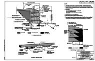
1. SCOPE<strong>Standard</strong> <strong>Method</strong> <strong>of</strong>Determining Longitudinal Surface Smoothness(California Type Pr<strong>of</strong>ilograph)FLH Designation: T 504-08EnglishI. Collection <strong>of</strong> DataFLH T 504-081.1 This test method is used to measure the smoothness <strong>of</strong> a pavement surface inmetric units by using a California type pr<strong>of</strong>ilograph. The pr<strong>of</strong>ilograph produces a hardcopy trace <strong>of</strong> the surface, from which deviations in the surface are identified and measured.2. EQUIPMENT2.1 Pr<strong>of</strong>ilograph - The pr<strong>of</strong>ilograph shall be a California type pr<strong>of</strong>ilograph consisting<strong>of</strong> a metal frame with multiple wheel trucks supporting each end and a center mountedmeasuring wheel. The unsupported length between the wheel tracks shall be 25 feet. Thepr<strong>of</strong>ilograph shall have steering capability.NOTE 1 - Insure equipment used is performing properly and is calibrated according to section3.0 CALIBRATION <strong>of</strong> this test procedure or according to the manufacture recommendations.2.1.1 The pr<strong>of</strong>ilograph shall be equipped with a graphic recorder capable <strong>of</strong> recordingthe distance <strong>of</strong> travel and the magnitude <strong>of</strong> vertical variation. The recorder shall have ahorizontal scale <strong>of</strong> 0.1 inches = 2.5 feet, and a vertical scale <strong>of</strong> 0.1 inches = 0.1 inches.2.2 Bump Location Template - The template shall consist <strong>of</strong> a piece <strong>of</strong> transparentplastic at least 5.0 inches long by 3.0 inches wide (See Figure A). A line, parallel to thelong side, shall be scribed on the template. This line shall be crossed with 2perpendicularly scribed lines 1.0 inches apart near the center <strong>of</strong> the template. Construct astraight slot through the template, parallel to the long side and 0.4 inches from the first linescribed. The slot shall extend the distance between the perpendicular lines previouslyscribed. The 1.0-inch line corresponds to a longitudinal distance <strong>of</strong> 25 feet on thelongitudinal scale <strong>of</strong> the pr<strong>of</strong>ilogram. The 0.4 inches distance between the parallel linesrepresents the maximum allowable bump in 25 feet.3.0 CALIBRATION3.1 Longitudinal (distance) Calibration - Check the longitudinal calibration beforeinitial use and at such other times as may be required for verification. Verify tire airpressure, as per manufacture recommendations. Operate the pr<strong>of</strong>ilograph over a measuredtest section on a reasonably flat and level surface for 528 feet in length. The length <strong>of</strong> thetest section as measured by the graphic recorder shall be within the following tolerance:Longitudinal calibration L / L R = 25.1 ± 0.5Where:L = length <strong>of</strong> test section in feet, nearest 0.01 feetL R = recorded length <strong>of</strong> test section in feet, nearest 0.01 inchesT504-1
FLH T 504-083.2 Vertical calibration - Check the vertical calibration before initial use and at suchother times as may be required for verification. Keep the pr<strong>of</strong>ilograph stationary. Usingpre-measured calibration blocks measured to the nearest 0.001 inches, pull or slide theblock(s) under the recording wheel. Measure the vertical trace line from the base line tothe peak and return. The trace line must return to the base line. Compare the actualheights <strong>of</strong> the calibration blocks with the heights <strong>of</strong> their vertical trace line. These heightsshould be within ± 0.003 inches.NOTE 2 - If the longitudinal and vertical calibration checks are not within the allowable tolerances specified,make the appropriate adjustments or repairs.4.0 PREPARATION4.1 Establish ground controls on the section <strong>of</strong> roadway to be tested. Controls shouldinclude the beginning and end with sufficient intermediate markers to facilitate correlation<strong>of</strong> areas on the graphic readout to the actual ground locations.4.2 Provide for traffic control including appropriate warning signs and flaggers.4.3 Assemble the instrument at the work site and perform the calibration procedures toassure that the equipment is operating properly.5.0 TESTING5.1 After determining that the pr<strong>of</strong>ilograph is operating properly, move to thebeginning point. Lower the measurement wheel, and run the test according to manufacturerecommendations.NOTE 3 - Do not back the instrument while the measuring wheel is on the pavement.5.2 Pr<strong>of</strong>ile the center <strong>of</strong> each lane <strong>of</strong> the project. Pr<strong>of</strong>ile continuously from beginningto end <strong>of</strong> project. Do not break pr<strong>of</strong>ile at excluded areas.5.3 Mark landmarks and excluded areas on the pr<strong>of</strong>ilogram for documentationpurposes. Mark the beginning and ending stations and identify the lane (either left or right)and the direction in which the trace is run (either ahead on line or back on line). Mark thetrace by making a spike or strum at least 1 inch long on the upside <strong>of</strong> the trace.NOTE 4 - Interrupting the test to add notes to the pr<strong>of</strong>ilogram will not interfere with the recording.Locations <strong>of</strong> physical features along the route such as mile markers, cross drains, bridge ends, guard railterminals, overhead utility crossings, etc. should be noted on the pr<strong>of</strong>ilogram. This will aid in matching theground locations with the graphic record. The trace should be marked and the station identifiedapproximately every 500 feet. Do not write on the trace line. Write notes at least 1 inch above or below theline.5.4 Operate the pr<strong>of</strong>ilograph at a speed no greater than a normal walk (1 to 3 miles/h)to eliminate as much bounce as possible.NOTE 5 - Asphalt materials may tend to be picked up and build-up on the pr<strong>of</strong>ilograph wheels causingnoticeable chatter on the trace. Wheels need to be cleaned <strong>of</strong>f periodically. Materials pickup on the wheelscan be minimized or eliminated by spraying the wheels lightly with WD-40.T504-2
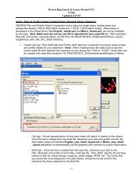
II. Pr<strong>of</strong>ile Trace and Data ReductionFLH T 504-086.1 Determine the smoothness [Pr<strong>of</strong>ile Index (PrI)] <strong>of</strong> each 0.1 mile section or sublot(N) is by using the ProScan Pr<strong>of</strong>ilogram Scanning System or an approved equal. TheProScan Pr<strong>of</strong>ilogram Scanning System is available from:Surface Systems & Instruments307 PlymateManhattan, KS 66502(800) 662-5656http://www.smoothroad.com/products/proscan/6.2 When using the ProScan Pr<strong>of</strong>ilogram Scanning System it is necessary to setdefault values for several parameters. The following default values shall be used:PRI & Scallop SettingsBlanking Band:0.00 InchesMinimum Height:0.035 InchesMinimum Width:2.00 FeetResolution0.039 InchesFilterFilter Type:Moving AverageFilter Length:2.000 FeetFilter Gain: 1.00Localized Roughness (Bumps)Defect Height0.400 InchesDefect Width25.0000 Feet6.3 When using the ProScan Pr<strong>of</strong>ilogram Scanning System it is necessary to identifyand mark the beginning point <strong>of</strong> the trace. It is also necessary to identify and mark allequations. Mark the trace by drawing a heavy vertical line on the trace at appropriatelocations. The vertical line should extend at least 2 inches above and below the trace.6.4 Scan the trace between marked beginning and ending points. The scanned tracemay consist <strong>of</strong> only one marked segment or it may consist <strong>of</strong> several segments. Providethe s<strong>of</strong>tware with appropriate stationing information at all beginning points. When anequation is encountered, provide the s<strong>of</strong>tware with the appropriate stationing information.Reposition the trace as necessary after reaching an ending point or equation.6.5 After scanning a trace, print a final report.6.6 Excluded areas for smoothness and bump determination are:6.6.1 25 feet from bridges6.6.2 Transverse joints with an existing pavement6.6.3 Cattleguards6.6.4 Horizontal curves with less than 500 foot radii6.6.5 Miscellaneous paved areas such as driveways, parking areas, turning orpassing lanes (less than 0.1 mile), and side roadsT504-3
FLH T 504-08Figure AT504-4