LONMSE 6M230 Control_Edit, Handbuch englisch - Warema
LONMSE 6M230 Control_Edit, Handbuch englisch - Warema
LONMSE 6M230 Control_Edit, Handbuch englisch - Warema

Create successful ePaper yourself
Turn your PDF publications into a flip-book with our unique Google optimized e-Paper software.
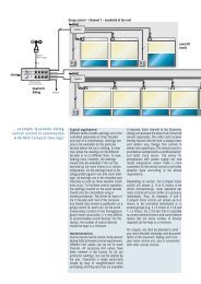
CONTROL_<strong>Edit</strong>1. Overview1.1 General information about CONTROL_<strong>Edit</strong>The CONTROL_<strong>Edit</strong> software application is used to create configuration files for LON ® motorcontrol units (MCUs) of the type <strong>LONMSE</strong> <strong>6M230</strong> with the Program ID 900057050A060400 ofWAREMA Renkhoff GmbH. The generated configuration files can be loaded into the configurablecontroller of the <strong>LONMSE</strong> <strong>6M230</strong> by means of an LNS plug-in:CONTROL_<strong>Edit</strong>ConfigurationfileLNS-Plug-in<strong>LONMSE</strong>Fig. 1-1:Schematic representation of working with configuration filesThe files determine the control behavior of the controllers. In addition it contains the basic settingsfor parameters, such as limits.We reserve the right to carry out improvements93232650•816863•7590k0•02.12.2005
C. Fehlen von Institutionen im bisher praktizierten Bilateralismus2. Autonomer NachvollzugZahllose Bundesgesetze.Bundesgericht interpretiert häufig europakonform.Unter institutionellen Gesichtspunkten unbefriedigende Situation.- Keine Pflicht zum Nachvollzug.- Keine Kontrolle des Nachvollzugs (wird überhaupt nachvollzogen, wirdrechtzeitig nachvollzogen, wird inhaltlich korrekt nachvollzogen).- Keine Vorlagemöglichkeit der Gerichte an den EuGH.- Fazit: Totaler Souveränitätsverlust ohne Garantie eines level playing field.- Keine Rechtssicherheit.- Beispiele.8
CONTROL_<strong>Edit</strong>2. For Your SafetyWe have developed and tested this software under observance of the fundamental safety requirements.Residual risks nevertheless remain!n Therefore read these instructions before you operate the control system the first time. Theyhelp you to get to know the functions of the software and to use them optimally.n Keep these instructions for future use!Hierarchic warnings are used in these instructions. They are identified by a warning sign in themargin and graded hierarchically as follows:1. WARNING2. ATTENTION3. CAUTIONWARNINGThe term WARNING is used as a warning against immediate imminent danger.Death or serious injuries may result (damage to persons).The term ATTENTION is used as a warning against a possible imminent danger.Death, serious or minor injuries (damage to persons), damage to property or damage to the environmentmay result.ATTENTIONCAUTIONThe term CAUTION is used as an application recommendation.Damage to property may result from non-observance.In addition to the hierarchic warnings described above we use the following symbol:n This symbol marks activities that you have to carry out or instructions that have to be observedunder all circumstances.2.1 Usage to the intended purposeThe CONTROL_<strong>Edit</strong> software application is used to create configuration files forLON ® motor control units (MCUs) of the type <strong>LONMSE</strong> <strong>6M230</strong> with the Program ID900057050A060400 of WAREMA Renkhoff GmbH. The generated configuration filescan be loaded into the configurable controller of the <strong>LONMSE</strong> <strong>6M230</strong> by means of anLNS plug-in:The approval of the manufacturer has to be obtained if the device is to be used to a purposedifferent to that described here. Usage which is not to the intended purpose can result in injuryto the user or third parties as well as damage to the device to the sun protection system or tothe moving mechanical parts of the complete system.ATTENTIONn Therefore always use our product to the intended purpose only!93232650•816863•7590k0•02.12.2005 We reserve the right to carry out improvements
CONTROL_<strong>Edit</strong>2.2 Target groupThese instructions are intended for persons who are commissioning a sun protection system inLonWorks technology as well as for trained specialists. A knowledge of the LonWorks technologyis required to this purpose.Operation by persons who are not sufficiently qualified and informed can cause severedamage to the system or even damage to persons!ATTENTIONn Initial operation may therefore only be carried out by correspondingly trained specialists! Thispersonnel must be able to recognize dangers which can be caused by the mechanical, electricalor electronic equipment!n Persons who perform initial operation on the system must know and have understood thecontents of these instructions.n The system parameters only need to be modified if the behavior of the control system is to beadapted or if a change has occurred at the sensor equipment.States of danger, malfunctions and material damage to the system are possible due toimproperly executed mounting, connection, repair or maintenance work!ATTENTIONn Such work may only be carried out by the service department or by authorized qualified personnel!2.3 General safety instructionsThe control system controls your sunblind automatically. You must therefore observe the followingsafety instructions:An automatically controlled mechanism can start moving unexpectedly!ATTENTIONn Therefore never place any objects in the area of an automatically controlled mechanism! Ensurethat there are no persons in the area of movement of automatically controlled sun protectionsystems during initial operation!n If measuring or test work has to be carried out on the active system, ensure that existing accidentprevention regulations are observed under all circumstances.CAUTIONThe complete system cannot function if the power fails. Therefore move your sunblindto a safe position in time if a storm may break loose! If the sunblind is operatedduring icing, all guarantees and liabilities expire! Changing Individual parameters canimpair the safety of the system or reduce its effectiveness! If you are not sure whateffect a change has, consult an expert.10We reserve the right to carry out improvements93232650•816863•7590k0•02.12.2005
CONTROL_<strong>Edit</strong>3. Installation of the Software3.1 System Requirements® PC with Windows XP® At least 32 MB free hard disk capacity, at least 64 MB RAM® Minimum screen resolution 1024x7683.2 Procedure for Installing the SoftwarennA basic knowledge of the used operating system is required in order to install/remove thesoftware!Open the CONTROL_<strong>Edit</strong> subdirectory on your installation CD. First read the file README.RTF. Start the installation program SETUP.EXE in the same directory. Follow the instructions ofthe installation program.nOpen the CONTROL_<strong>Edit</strong>_000 subdirectory on your installation CD. First read the file READ-ME.RTF. Start the installation program SETUP.EXE in the same directory. Follow the instructionsof the installation program.Note: Do not delete or move any files that were created during the installation by the installationprogram.3.3 RemovalThe software can be removed by using the <strong>Control</strong> Panel of your computer.93232650•816863•7590k0•02.12.2005 We reserve the right to carry out improvements 11
CONTROL_<strong>Edit</strong>4. Starting the SoftwareIn order to use CONTROL_<strong>Edit</strong> start the program via the Windows-Start menu. In the dropdownmenu of the input window select the entry <strong>LONMSE</strong> <strong>6M230</strong>/ 900057050A060400 and then clickthe [OK] command button:Fig. 4-1:Starting the softwareAn empty input window is displayed:Fig. 4-2: Empty input windown In the menu bar select the [Open] command in the [File] menu and open the file [Blind_Demo_CE_0]. This is located on your installation CD or can be obtained from WAREMA.12We reserve the right to carry out improvements93232650•816863•7590k0•02.12.2005
CONTROL_<strong>Edit</strong>5. Explanation of the user interface5.1 OverviewThe following figure shows the user interface of the software. This window is divided into severalsections:A) Title bar: This row displays the name of the program and the file name, for example WARE-MA CONTROL_<strong>Edit</strong> [Drive:] \ [Directory] \ [Blind_Demo_CE_0.ini], depending on the file thatyou have opened.B) Menu bar: The menu bar contains the menus [File], [<strong>Edit</strong>], [Options] and [Info].C) Toolbar: The toolbar makes the most commonly used functions of the menu bar available asicons.D) Structure view: The input window to be edited is selected in this section. Click a „Plus“ iconin order to open further sublevels of the structure. Click a „Minus“ icon in order to close thesublevel of the structure.BCAEDFig. 5-1:Software user interfaceE) Input window: This section fulfils several functions. Its appearance depends on the selectionthat you made in the structure view. You can display data, modify parameters or start andmonitor the simulation mode.93232650•816863•7590k0•02.12.2005 We reserve the right to carry out improvements 13
CONTROL_<strong>Edit</strong>5.2 The menu barWhen you click the individual menus, these fold down and commands that can then be selectedare displayed.5.2.1 The [File] menu5.2.1.1 [New]This command corresponds to the icon icon in the toolbar. This command is used to createa new „empty“ record. Only the input „Auto Timer“ and the command „State after Reset“ existin the record.5.2.1.2 [Open...]This command corresponds to the iconfile that was created with CONTROL_<strong>Edit</strong>.icon in the toolbar. This command is used to open a5.2.1.3 [Wizard...]This command corresponds to the iconthe Wizard.icon in the toolbar. This command is used to start5.2.1.4 [Save]This command corresponds to the icon icon in the toolbar. This command is used to savethe current file under the name displayed in the title bar.5.2.1.5 [Save as...]This command is used to save the current file under a different name.5.2.1.6 [Exit]This command is used to terminate the program.5.2.2 The [<strong>Edit</strong>] menu5.2.2.1 [Undo]This command corresponds to the iconup to 25 editing steps.icon in the toolbar. This command is used to undo5.2.2.2 [Redo]This command corresponds to the icon icon in the toolbar. This command corresponds tothe icon in the toolbar. This command is used to restore up to 25 editing steps that had been undone.14We reserve the right to carry out improvements93232650•816863•7590k0•02.12.2005
CONTROL_<strong>Edit</strong>5.2.2.3 [Check data]The current data can be checked to see whether they are free of errors. The following checks canbe carried out.® Deadlock: A check is carried out whether a state that has been reached once can possibly nolonger be exited.® Loop: A check is carried out whether a loop results from the data input.® Receiverheartbeatstates: A check is carried out whether the result states of the Receiverheartbeatfunction are also actually defined at the [Commands].® Lost State: Finding of states that can never be reachedThe result of the check is displayed in an information window. The data are not corrected automatically.93232650•816863•7590k0•02.12.2005 We reserve the right to carry out improvements 15
CONTROL_<strong>Edit</strong>5.2.3 The [Options] menu5.2.3.1 [Language changeover]When delivered the software supports the languages [German] and [English], i.e. all the texts ofthe user interface are displayed in German or English, depending on the selection made here.5.2.3.2 [Revision control enabled]The configuration files that you create using CONTROL_<strong>Edit</strong> are differentiated by the combinationof [File name] and [Revision] that you can specify in the [General information] window.Example: Have a look at an LNS project consisting of several devices. Different configurationfiles can exist in the individual controllers of the devices so that the controllers have different controlbehaviors. These configuration files have to differ in their [File name] and/or [Revision]. Thesame designation at different control behaviors can lead to conflicts.Therefore, if you want to change the control behavior, you should modify the name and/or revisionof the configuration file before storing it.Note: A modification of the basic settings of the parameters (e.g. limits or move commands)does not require the file name and/or revision to be modified.The following modifications change the control behavior and require a change in the file nameand/or revision:® Modification of the number of inputs® Modification of the number of [Commands]® Renaming of inputs and [Commands]® Modification of the window type of an input® Modification of the window type of [Commands]® Modification of the status „Visible in plug-in“ at inputs and move commands® Modification of the background and text color of [Commands]® Modifications in the „List/Simulation“ windowCONTROL_<strong>Edit</strong> monitors these modifications and offers to increase the revision during saving, ifappropriate. If increasing the revision is not carried out, an error message can occur when a configurationfile is loaded into the controller of a MCU, if another configuration file with the same filename/revision but a different control behavior already exists in another controller in the same project.Note: We advise that you activate the revision check.5.2.4 The [Info] menuDisplay the software version as well as address of WAREMA.16We reserve the right to carry out improvements93232650•816863•7590k0•02.12.2005
CONTROL_<strong>Edit</strong>6. The WizardCONTROL_<strong>Edit</strong> disposes of an Wizard in order to allow rapid creation of a simple control behavior.It is called up via the [Wizard...] item in the [File] menu.This command corresponds to the iconin the toolbar.If you are not so experienced as a user, you should use a PC to follow this section. This providesyou with an important basis for understanding the following chapter.We advise that you use the following working method:n Use the Wizard to create the desired control behavior. You thus already dispose of an expandablebasis for your required control behavior.n If necessary, adapt the control behavior using the <strong>Control</strong>_<strong>Edit</strong> functions. For more informationplease read the following chapter.n Use the CONTROL_edit simulation functions to test the control behavior. Please read Chapter9 for further information.n Save the result in a configuration filen You can load the file into the controller of the <strong>LONMSE</strong> <strong>6M230</strong> by using the LNS plug-inGeneral Information about the WizardThe Wizard consists of a total of eight windows that can be edited independently of each other.Navigation between the individual windows of the Wizard is carried out by clicking the commandbuttons [1] to [8] or [].Note: When the Wizard has been terminated, the generated data cannot be opened again withthe Wizard. The Wizard overwrites all the data that were previously entered manually. Thereforesave all the previously created control behaviors before you use the Wizard!The Wizard creates configuration files for use in a Blinds controller of the <strong>LONMSE</strong> <strong>6M230</strong>. Youhave to carry out some changes in order to obtain configuration files for a Lights controller. Pleasealso read Section 10 for further information.n Now start the Wizard!93232650•816863•7590k0•02.12.2005 We reserve the right to carry out improvements 17
CONTROL_<strong>Edit</strong>6.1 The [Product type] windowIn this window a (sun protection) product type is selected and a name for the control behavior isentered. Through the selection of a product type sensible settings are already carried out in thenext windows. However, these can be modified subsequently. Note: Select the [Other products]entry if the desired sun protection product is not listed. In this case no settings are carried out inthe next windows of the Wizard. [Product type] and [Name] have to be specified. Otherwise thesubsequent input windows cannot be accessed.n Select the [External venetian blinds] product and enter the name [Demo project] for the controlbehavior:Fig. 6-1:Window 1, Product typen Call up the next window.18We reserve the right to carry out improvements93232650•816863•7590k0•02.12.2005
CONTROL_<strong>Edit</strong>6.2 The [Sun control] windowThe parameters for the sun control are set in this window. If no sun control is required, removethe check mark in the [Sun control] checkbox.<strong>Control</strong> behavior: If the [Limit sun] is exceeded, the [Move command Sun] is carried out. If thevalue falls below the [Limit cloud], the [Move command Cloud] is carried out.n Please leave the preset settings unchanged, the window is now shown as follows:Fig. 6-2:Window 2, Sun controlThe following settings are possible in the input window:CP Range of values ResolutionRemarkSun control Yes / No - If the checkbox is deactivated, no entriesare possible in the input window.Limit sunLimit cloudMove commandSun/CloudMove commandSun/CloudMove commandSun/CloudUsed networkvariablesCloud before Sun0...131 klxInvalid0...131 klxInvalidSET_OFF, SET_ONSET_DOWN, SET_UPSET_STOPSET_STATE, Invalid0...100 %Invalid-359...+360°InvalidnviLuxAstro0nviLuxAstro1n Call up the next window.0,002 klx If [Invalid] is entered, the [Sun movecommand] is never executed.0,002 klx If [Invalid] is entered, the [Cloudmove command] is never executed.- If [Invalid] is entered, the [Cloud/Sunmove command] is never executed.0,5 % If [Invalid] is entered, the positionof the sun protection remains unchanged.0,02° If [Invalid] is entered, the slat angleof the sun protection remains unchanged.- The [Used network variables] optionspecifies which network variable is tobe evaluated.If the check mark is removed in the[Cloud before Sun] checkbox, the[Sun move command] must havebeen executed at least once beforethe [Cloud] move command can beexecuted.93232650•816863•7590k0•02.12.2005 We reserve the right to carry out improvements 19
CONTROL_<strong>Edit</strong>6.3 The [Wind monitoring] windowThe parameters for the wind monitoring are set in this window. If no wind monitoring is required,remove the check mark in the [Wind monitoring] checkbox.<strong>Control</strong> behavior: If the [Upper limit] is exceeded, the [Move command] is carried out. All [Commands]remain blocked until the value drops below [Lower limit] again.n Please leave the preset settings unchanged, the window is now shown as follows:Fig. 6-3:Window 3, Wind monitoringThe following settings are possible in the input window:CPRange of valuesResolutionRemarkWind monitoring Yes / No - If the checkbox is deactivated, no entriesare possible in the input window.Upper limitlower limitMove command0...6553,4 m/sInvalid0...6553,4 m/sInvalidSET_OFFSET_ONSET_DOWNSET_UPSET_STOPSET_STATEInvalidMove command 0...100 %InvalidMove command -359...+360°InvalidUsed networkvariablesn Call up the next window.nviWindSpeed0nviWindSpeed10,1 m/s If [Invalid] is entered, the [Move command]is never executed.0,1 m/s If [Invalid] is entered, no other [Commands]are executed after the executionof [Move command].- If [Invalid] is entered, the [Move command]is never executed.0,5 % If [Invalid] is entered, the position of thesun protection remains unchanged.0,02° If [Invalid] is entered, the slat angle of thesun protection remains unchanged.- The [Used network variables] option specifieswhich network variable is to be evaluated.20We reserve the right to carry out improvements93232650•816863•7590k0•02.12.2005
CONTROL_<strong>Edit</strong>6.4 The [Manual operation] windowThe parameters for manual operation are set in this window. If no manual operation is required,remove the check mark in the [Manual operation] checkbox.<strong>Control</strong> behavior: A period of 120 minutes is specified for the [Dwell time] entry. After manualoperation all the automatic functions are blocked for this period. After this period has expired, theautomatic functions are active again.n Please leave the preset settings unchanged, the window is now shown as follows:Fig. 6-4:Window 4, manual operationThe following settings are possible in the input window:CPRange of valuesResolutionRemarkManual operation Ja / Nein - If the checkbox is deactivated, the [Dwelltime] input field is deactivated.Dwell time0...254 minInvalidn Call up the next window.1 min If [Invalid] is entered, the automatic functionsare always blocked.93232650•816863•7590k0•02.12.2005 We reserve the right to carry out improvements 21
CONTROL_<strong>Edit</strong>6.5 The [Timer switch] windowThe parameters for up to four timers are set in this window. If no timers are required, remove thecheck mark in the [Timer 1] to [Timer 4] checkboxes. You can program up to 4 timers, 2 of themfor workdays and 2 for weekends. By default all the timers are deactivated.<strong>Control</strong> behavior: The timers are activated by clicking the [Timer 1 workday], [Timer 2 workday],[Timer 1 weekend], [Timer 2 weekend] checkboxes. The move commands are executed at the setmoment.n Click the [Timer 1] and [Timer 2] checkboxes. The check mark is displayed. The window is nowdisplayed as follows:Fig. 6-5:Window 5, timer switchThe following settings are possible in the input window:CP Range of values Resolution RemarkTimer 1 WorkdayTimer 2 WorkdayTimer 1 WeekendTimer 2 WeekendTime 00:00:00...23:59:59Move commandYes/No - If the checkbox is deactivated, noentries are possible in the input windowlying below it.SET_OFFSET_ONSET_DOWNSET_UPSET_STOPSET_STATEInvalidMove command 0...100 %InvalidMove command -359...+360°Invalidn Call up the next window.1 s Moments at which move commandsare executed. A difference is madebetween weekdays and weekends.- If [Invalid] is entered, the [Movecommand] is never executed.0,5 % If [Invalid] is entered, the positionof the sun protection remains unchanged..0,02° If [Invalid] is entered, the slat angleof the sun protection remains unchanged.22We reserve the right to carry out improvements93232650•816863•7590k0•02.12.2005
CONTROL_<strong>Edit</strong>6.6 The [Scenes] windowUp to four "Scenes" can be defined in this window. If no scenes are required, remove the checkmark in the [Scene 1] to [Scene 4] checkboxes. You can program up to 4 scenes. By default allthe scenes are deactivated. First activate the scenes that you want to use. Now specify the inputvariable and the scene number.<strong>Control</strong> behavior: If a [SceneRecall] command with the specified [Number] is received at thespecified input variable, the set move command is executed. Subsequently the automatic functionsremain deactivated for the set [Dwell time].n Click the [Scene 1] checkbox. The check mark is displayed. The window is now displayed asfollows:Fig. 6-6:Window 6, ScenesThe following settings are possible in the input window:CP Range of values Resolution RemarkScene 1Scene 2Scene 3Scene 4Input variableYes / No - If the checkbox is deactivated, noentries are possible in the input windowlying below it.nviScene0nviScene1- Specifies at which network variablethe [Scene Recall] command withthis number is to be received in orderfor the move command to be executed.Number 0...255 1 If the [Scene Recall] command withthis number is received at the specifiednetwork variable, the movecommand is executed.Move commandMove command 0...100 %InvalidSET_OFF, SET_ONSET_DOWN, SET_UPSET_STOPSET_STATE, InvalidMove command -359...+360°InvalidDwell time0...254 minInvalidn Call up the next window.- If [Invalid] is entered, no move commandis executed.0,5 % If [Invalid] is entered, the position ofthe sun blind remains unchanged.0,02° If [Invalid] is entered, the slat angleof the sun blind remains unchanged.1 min If [Invalid] is entered, the automaticfunctions always remain blocked.93232650•816863•7590k0•02.12.2005 We reserve the right to carry out improvements 23
CONTROL_<strong>Edit</strong>6.7 The [Rain control] windowThe parameters for the Rain control are set in this window. If no Rain control is required, removethe check mark in the [Rain control] checkbox.<strong>Control</strong> behavior: The <strong>LONMSE</strong> <strong>6M230</strong> does not dispose of a Rain control function. The evaluationof a corresponding sensor must therefore be carried out by another device. In case of rainthis device supplies a scene with a defined number to the <strong>LONMSE</strong> <strong>6M230</strong>. When this commandis received, the set move command is carried out.n Please leave the preset settings unchanged, the window is now shown as follows:Fig. 6-7:Window 7, Rain controlThe following settings are possible in the input window:CPRange of valuesResolutionRemarkRain control Yes / No - If the checkbox is deactivated, no entriesare possible in the input windowlying below it.Input variablenviScene0nviScene1- Specifies at which network variablethe [Scene Recall] command with thisnumber is to be received in order forthe move command to be executed.Number 0...255 1 If the [Scene Recall] command withthis number is received at the specifiednetwork variable, the move commandis executed.Move commandSET_OFFSET_ONSET_DOWNSET_UPSET_STOPSET_STATEInvalidMove command 0...100 %InvalidMove command -359...+360°Invalidn Call up the next window.- If [Invalid] is entered, no move commandis executed.0,5 % If [Invalid] is entered, the position ofthe sun blind remains unchanged.0,02° If [Invalid] is entered, the slat angle ofthe sun blind remains unchanged.24We reserve the right to carry out improvements93232650•816863•7590k0•02.12.2005
CONTROL_<strong>Edit</strong>6.8 The [Finish Wizard] windowWhen you arrive at this input window, you can accept the data into the user interface of CON-TROL_<strong>Edit</strong> and exit the Wizard:n Click the [Finish Wizard] command button. A prompt may be displayed whether you want tosave the data still on the user interface before they are overwritten. If you still require thesedata, store them in the window that is displayed.n Subsequently the data that were created using the Wizard are taken over into the user interface.However, the generated data have not been saved yet. From the [File] menu select the[Save] entry and save the file under the name "Test_Project".orn Click the [Abort] command button in order to terminate Wizard immediately without takingover the data. All the entered data are lost.n You can return at any time to the individual windows as long as the Wizard has not been terminated.However, it is not possible to start the Wizard with existing data.Fig. 6-8:Window 8, Exiting WizardYou have now entered all the required data and can revise the control behavior using CONTROL_<strong>Edit</strong> or carry out a simulation of the control system. Please read the next chapter for more information.93232650•816863•7590k0•02.12.2005 We reserve the right to carry out improvements 25
CONTROL_<strong>Edit</strong>7. Working in the Structure ViewWhen you have created your control behavior using the Wizard as described in Chapter 6, the followingstructure view is displayed after you have terminated the Wizard. The structure view is positionedon the left-hand side of the user interface and presents the control behavior in a wellstructuredform. The corresponding input windows are called up by selecting the entries. Thestructure view contains:® The name that you assigned in the [Name] input field in the Wizard, with the index [Rev.0] asthe extension. Note: The revision index is initially set automatically to [Rev0].® The [General informations] entry, Section 8.1® The [Inputs] folder, Section 8.2® The [<strong>Control</strong>ler response] folder, Section 8.3® The [Commands] folder, Section 8.4® The [Receiverheartbeat] entry, Section 8.5.n All the folders are already opened. If not, click a "Plus" icon in order to open a folder. Click a"Minus" icon in order to close the folder again.Fig. 7-1:Structure view26We reserve the right to carry out improvements93232650•816863•7590k0•02.12.2005
CONTROL_<strong>Edit</strong>7.1 The pop-up menuThe structure view is context-sensitive. This means: If you right-click an entry, various commandsare displayed in a pop-up menu (context menu) for selection. The Wizard has already created thebasic structure of the control behavior. In the structure view you can extend or adapt the functionalityof your control behavior by carrying out one of the following functions at inputs and [Commands]® deleting® adding® copyingNote: Pop-up menus are only available for the [Inputs] and for the [Commands]. In the followingsection we will describe the pop-up menus for the [Inputs]. However, the functions also apply forthe [Commands]. No pop-up menus are available for the entries [General information], [<strong>Control</strong>lerresponse] and [Receiverheartbeat].7.1.1 [New] pop-up menun Right-click the [Inputs] folder in the structure view. The pop-up menu is displayed. Select[New] in order to define a new input. Name the new input. The [Inputs] folder may contain upto 24 inputs.Fig. 7-2:Creating a new input93232650•816863•7590k0•02.12.2005 We reserve the right to carry out improvements 27
CONTROL_<strong>Edit</strong>7.1.2 [Delete] pop-up menun Right-click an input in the structure view. The pop-up menu is displayed. Select [Delete] in orderto delete an input:Fig. 7-3:Deleting an input28We reserve the right to carry out improvements93232650•816863•7590k0•02.12.2005
CONTROL_<strong>Edit</strong>7.1.3 [Copy] pop-up menun Right-click an input in the structure view. The pop-up menu is displayed. Select [Copy] in orderto copy the input. A further input with identical parameters is created. The original name is extendedby an index because identical names may not exist at inputs.Fig. 7-4:Copying an inputNote: Although the [AutoTimer] can be copied, only one input of the type [AutoTimer] is allowedin a file. If this is not observed, the function of the configuration file can be impaired.7.1.4 Moving inputsInputs and [Commands] can be sorted as required by simply dragging-and-dropping them:n Click an input in the structure view. The input is selected.n Drag the input to a different position while keeping the mouse button pressed.Note: Moving is only possible within a folder.93232650•816863•7590k0•02.12.2005 We reserve the right to carry out improvements 29
CONTROL_<strong>Edit</strong>8. The Input and Display WindowsThe input and display window is positioned on the right-hand side of the user interface. The contentsof the window depend on the entry selected in the structure view:8.1 General informationsIf this entry is selected in the structure view, the following input window is displayed. You can enterfundamental information in this window:Fig. 8-1:The [General informations] windowThe following settings are possible in the input window:Setting Range of values RemarkFile typeWAREMA controllerdescriptionCannot be modifiedFile format version 1.0 Cannot be modifiedDevice/Program ID <strong>LONMSE</strong> <strong>6M230</strong>/900057050A060400<strong>Control</strong>lertype/ObjectIDNameBlinds <strong>Control</strong>ler/22003Light <strong>Control</strong>ler/22005String, maximum of300 charactersCannot be modified-The name is already specified when the fileis created with „New“, „Open“ or „Wizard“.It can be changed subsequently here.30Technische Änderungen behalten wir uns vor93232650•816863•7590k0•02.12.2005
CONTROL_<strong>Edit</strong>Setting Range of values RemarkRevision 0...99 The files are differentiated by Name/Revisionin the LNS project in which the fileis to be used. If the control behavior haschanged, the name and/or the revisionshould be changed before the configurationfile is saved again (for further informationplease read Section 5.2.3.2)DescriptionString, maximum of300 charactersEnter a text as a description of your configurationfile here. This text is displayed in theplug-in when the configuration file is loadedinto the controller.Date - Enter the date of creation here. If a new filewas created, the current date is entered automatically.Designer String, maximum of 20charactersFig. 8-2:Possible settingsIf a new file was created, the user name ofthe user who is logged on is entered automatically.If a log-on did not take place, thename has to be entered manually.Note: Invalid value settings in the input fields are indicated by a red background.93232650•816863•7590k0•02.12.2005 Technische Änderungen behalten wir uns vor 31
CONTROL_<strong>Edit</strong>8.2 InputsIf you select an input in the structure view, the [Input and display] window is divided into twoblocks.The upper block contains general information for the respective input and always has the sameappearance:Fig. 8-2:Input and display window® [Name] of the respective input, e.g. "Wind monitoring", "Timer switch". The entry can be modifiedand is displayed in the structure view under [Inputs].® [Type of window], several settings can be selected here. Please read the following section forfurther information. After a window type has been selected, the parameters for the respectiveinput are available in the lower block in a suitable input format. When the window type ischanged, the available input fields in the lower block have sensible data pre-assigned. You canmodify these data manually.® [Visible in plugin]: When this checkbox is selected, you can specify whether the correspondinginput window is to be displayed in the plug-in of the <strong>LONMSE</strong> <strong>6M230</strong>. If the checkbox is notactivated, you cannot change the limit for this Input in the plug-in during editing later.8.2.1 Window types of the inputsA window type represents the function of an input. Inputs can, for example, be of the type[Brightness], [Wind limit] or [Manual operation]. The appearance of the windows in the lowerblock of the user interface correspondingly also differs - Different window types.The appearance of the lower block depends on the [Type of window] that you select in the upperblock, in the following example [Type of window] = "Wind limit":Fig. 8-3:The "Wind limit" window type32Technische Änderungen behalten wir uns vor93232650•816863•7590k0•02.12.2005
CONTROL_<strong>Edit</strong>Note: A newly generated input is always of the window type [Raw data]. Simplest procedure:Create an input in the structure view and then edit it in the input window. Select the input type inthe [Type of window] menu that you require for your control behavior. The input is then renamedautomatically and has the same designation in the structure view as in the [Name] input field. Afterwardsyou can assign a name freely to the input.You can select the following window types:® Wind limit® Heating demand® Cooling demand® Timer® Scene recall® Scene learn® Presence® Brightness® Annual shade diagram® Manual operation® Day of week® AutoTimer® Window contact® Raw dataFurther information about the available input variables can be found in the plug-in manual for<strong>LONMSE</strong> <strong>6M230</strong>, Art. No. 816 861.93232650•816863•7590k0•02.12.2005 Technische Änderungen behalten wir uns vor 33
CONTROL_<strong>Edit</strong>8.3 <strong>Control</strong>ler response8.3.1 Block graphicFig. 8-4:The block view of a controller.An overview of the controller function is displayed in the block view of the control behavior. Thedisplay consists of rectangles with different designations and colors. Each of these rectanglesrepresents a "state" which the controller can be in. After the device has been reset, the controlleris in the state displayed at the extreme left (In this case "State after reset"). Arrows indicate betweenwhich states the controller can change. Accordingly, states can always only change in thearrow direction from left to right.If the state at the right-hand edge of the display has been reached, the sequence is continued in arectangle with the same designation and color that is positioned further to the left and that againhas a subsequent state.If the controller reaches a new state, a move command can be carried out. If you want to create anew move command, open the [Commands] folder in the structure view and there create a newcommand by means of the pop-up menu. Please also read Section 7 for further information.Further information about the control behavior can be found in the plug-in manual for <strong>LONMSE</strong><strong>6M230</strong>, Art. No. 816861.34Technische Änderungen behalten wir uns vor93232650•816863•7590k0•02.12.2005
CONTROL_<strong>Edit</strong>8.3.2 The [List/Simulation] viewFig. 8-5:The [List/Simulation] viewIn the [List/Simulation] view you can have the transition conditions from one state to anotherstate displayed and edit them. You can insert new rows. A new rows corresponds to a furthercondition under which a transition to another state is carried out. Example: The row with the Index0 specifies how the controller changes from the "State after reset" to the "Wind" state afterswitching on. The conditions that have to be fulfilled for the input so that a state changes are listedin the fields between the columns "State" and "Next state". In the example the transition to the"Wind" state takes place when the "Wind" input is fulfilled. All the other inputs are ignored.8.3.2.1 Inserting a new row (new transition condition):n Select the desired initial state in the lower block under [State] and click the [New] commandbutton. The new row is inserted at the suitable position and the [Index] column renumberedcorrespondingly.Fig. 8-6: Click the [new] command button in order to insert a new row.93232650•816863•7590k0•02.12.2005 Technische Änderungen behalten wir uns vor 35
CONTROL_<strong>Edit</strong>8.3.2.2 Deleting a rown Select the row to be deleted by clicking in the gray field next to the index number. The row isselected. Now press the key [Del] on your keyboard. A security prompt is displayed. Confirmwith [Yes] in order to delete the row. Note: If a row was deleted unintentionally, this processcan be reversed by using [Undo].8.3.2.3 Moving a rowYou can move individual lines in order to obtain a better overview. Note: Lines can only be movedwithin a block with the same initial state.n Select the row to be moved by clicking in the gray field next to the index number. The row isselected. Then right-click in the index row to which the row is to be moved. Click the [Moverow] command button. The row is inserted above the selected row.8.3.2.4 Changing the subsequent stateIf required you can modify the subsequent state of a row at any time.n Click in the [Next state] column on the corresponding row. Select the desired subsequentstate from the dropdown menu.8.3.2.5 <strong>Edit</strong>ing the transition conditionsIf necessary, you can modify the transition conditions at any time. Possible settings:[Y] = Yes[N] = No[-–] = Don‘t caren Click in the corresponding field until the desired transition condition is displayed.If you want to modify a whole group of transition conditions, proceed as follows:n Select the first field in the group. Drag a frame around the desired group while keeping theleft mouse button pressed. Then right-click on the selected group. Select the desired transitioncondition in the pop-up menu.8.3.2.6 Copying transition conditionsIf necessary, you can copy transition conditions of a whole group and insert them at another position.n Drag a frame around the desired group while keeping the left mouse button pressed. Thenright-click on the selected group. Select the [Copy] entry in the pop-up menu. Use the righthandmouse button to select the upper left-hand corner of the area into which the copied transitionconditions are to be inserted. Select [Insert] from the pop-up menu.36Technische Änderungen behalten wir uns vor93232650•816863•7590k0•02.12.2005
CONTROL_<strong>Edit</strong>8.4 CommandsIf a command is selected in the structure view, the input window is divided into two blocks.The upper block contains general information for the respective command and always has thesame appearance:Fig. 8-7:Commands® [Name] of the respective command, e.g. "Wind". The entry can be modified and is displayed inthe structure view under [Commands].® [Type of window], several settings can be selected here. Please read the following section forfurther information. After a window type has been selected, the move command can be enteredin the desired format. You can modify these data manually.® [Visible in plugin]: When this checkbox is selected, you can specify whether the correspondingwindow is to be displayed in the plug-in of the <strong>LONMSE</strong> <strong>6M230</strong>. If the checkbox is not activated,you cannot change this command in the plug-in during editing later.® [Back color]: The command is displayed in color in the block graphics. Change the color herein order to improve the overview in the block graphics, since a command can occur at severalpositions in the block graphics.® [Text color]: The command is displayed in the block graphics. Change the text color here in orderto improve the overview in the block graphics. You can set black or white8.4.1 Window typesA window type represents the function of a command. Commands can be of the type [Raw data],[SNVT_Setting with slat tracking] or [SNVT_Switch without slat tracking]. The appearance of thewindows in the lower block of the user interface correspondingly also differs - Different windowtypes.Note: The settings [SNVT_Setting with Slat tracking] is advisable for a sun protection control system,the setting [SNVT_Switch without Slat tracking] is advisable for controlling lighting equipment.The <strong>LONMSE</strong> <strong>6M230</strong> disposes of both blinds and lights controller objects. For further informationplease also refer to Section 8.1. Depending on the controller type that is set in the [Generalinformations] window the suitable window type of the Commands is set automatically.93232650•816863•7590k0•02.12.2005 Technische Änderungen behalten wir uns vor 37
CONTROL_<strong>Edit</strong>The appearance of the lower block depends on the [Type of window] that you select in the upperblock, in the following example [Raw data]:Fig. 8-8:"Raw data" input windowNote: The Commands are only preliminary assignments that you can edit in the input window.Simplest procedure: Create a command in the structure view and then edit it in the input window.Select the command type in the [Type of window] menu that you require for your control behavior.8.4.1.1 Raw dataIn the [Raw data] setting the [Move Command] is entered with a length of 4 bytes in hexadecimalformat:Fig. 8-9:Raw data8.4.1.2 SNVT_Setting with Slat trackingFig. 8-10:SNVT_Setting with slat trackingThe following settings are possible in the [SNVT_Setting with Slat tracking] setting:CP Range of values ResolutionMove command.functionMove command.settingMove command.rotationSET_UPSET_DOWNSET_STOPSET_STATESET_ONSET_OFFInvalid0...100%Invalid-359°...360°Invalid-0,5%0,02°Fig. 8-11:Possible settings38Technische Änderungen behalten wir uns vor93232650•816863•7590k0•02.12.2005
CONTROL_<strong>Edit</strong>8.4.1.3 SNVT_Switch without Slat trackingFig. 8-12:SNVT_Switch without Slat trackingThe following settings are possible in the [SNVT_Switch without Slat tracking] setting:CP Range of values ResolutionMove command.value 0...100%InvalidMove command.stateFig. 8-13:Possible settingsOFFONInvalid0,5%-93232650•816863•7590k0•02.12.2005 Technische Änderungen behalten wir uns vor 39
CONTROL_<strong>Edit</strong>8.4.2 Specification of the commandA command can be defined for each state of the controller. The command is executed as soon asthe MCU reaches the state indicated in [Name].Fig. 8-14:Command input window, in this example "Wind"® [Visible in plugin]: When this checkbox is selected, you can specify whether the correspondinginput window is to be displayed in the plug-in of the <strong>LONMSE</strong> <strong>6M230</strong>. If the checkbox is notactivated, you cannot change this command in the plug-in during editing later.The following options can be selected in the lower section of the input window:8.4.2.1 [No operation]If the controller takes the state specified in [Name], no move command is sent. Application: In the[Manual operation] state, not the defined move command but rather the move command fromnviManSwitch is to be sent.8.4.2.2 [Learn scene]If the controller assumes the state specified in [Name], the move command of the state in the[Output state] field is changed. The new move command is the value that is valid at the networkvariable nviFeedback of the respective controller at the moment when the [Name] state is assumed.8.4.2.3 [Slat tracking]Up to four slat tracking tables can be defined in the plug-in of the <strong>LONMSE</strong> <strong>6M230</strong>. If the controllerassumes the state specified in [Name] and if one of the slat tracking functions is selected, thecurrently valid value from the corresponding slat tracking table is sent as the move command. Assoon as the position of the sun results in a new value of the slat tracking table and the state specifiedin [Name] still exists, the new value is sent.Note: If the window type [SNVT_Switch without slat tracking] is selected, the slat tracking cannotbe selected8.4.2.4 [Manual operation enabled]When this checkbox is selected, you can specify whether manual operation is to be enabled forthe state displayed in [Name]. If the checkbox is not activated, manual operation is disabled.Safety instruction: Manual operation may not be enabled in a [Wind alarm] state because thesun protection has to remain in a safe position in this case.40Technische Änderungen behalten wir uns vor93232650•816863•7590k0•02.12.2005
CONTROL_<strong>Edit</strong>8.4.2.5 [AutoTimer]The AutoTimer is a counter that is integrated in the controller. If the controller assumes the statespecified in [Name], the AutoTimer is set to the set value and is counted down to 0 automatically.You can enter the initial value of the AutoTimer in the [AutoTimer] input field. Values from 0 to 254can be set. If [Invalid] is set, the AutoTimer is not counted down, but is rather always fulfilled. Youcan specify in the [Inputs] folder under [AutoTimer] in the structure view whether the AutoTimeris to be counted down in minute or second cycles.Note: The Auto Timer can be evaluated as an input. As long as its value has not yet been counteddown to 0, this input is fulfilled. Application: You can use the AutoTimer for example to disable thecomfort functions after manual operation - the controller cannot return to the "Sun" state until theAutoTimer has expired.93232650•816863•7590k0•02.12.2005 Technische Änderungen behalten wir uns vor 41
CONTROL_<strong>Edit</strong>9. The Simulation Mode9.1 <strong>Control</strong>ling the Simulationn Select the [Simulation] checkbox in the lower block of the input window. The following windowis displayed:Fig. 9-1:Activated simulation modeNote: All the operating and input options are disabled when the simulation mode is activated. Theprogram cannot be terminated during simulation.The following operating and display elements exist in the upper block of the input window:9.1.1 [Start]Click the command buttonin order to start the simulation.9.1.2 [Pause]Click the command buttonin order to pause or continue the simulation.9.1.3 [Stop]Click the command buttonin order to stop the simulation.93232650•816863•7590k0•02.12.2005 We reserve the right to carry out improvements 43
CONTROL_<strong>Edit</strong>9.2 Changing input conditionsAfter simulation has been started, you can test the behavior of the control system under differentcombinations of the input states. Observe the upper row in the display window to this purpose:Each input disposes of an entry, with the following meaning:[Y] If [Y] (YES) is displayed on a gray background, the input is reserved, but not yet fulfilled. Duringthe next execution of the table the background is displayed in yellow and is then really fulfilled.[N] The input is not fulfilled (NO)n Click in the entry of the [Wind] input. The value changes from [N] to [Y]. The input is now reservedfor change and will change its state during the next execution of the table:Fig. 9-6:Changing input conditionsDuring the next execution of the table the change becomes effective and the entry then has ayellow background. The sequence is identical during the transition from [Y] to [N].Fig. 9-7:Changing input conditionsNote: The [Manual operation], [Scene] and [Timer] inputs are only evaluated once. They are automaticallyreset to [N] after the table has been executed.46We reserve the right to carry out improvements93232650•816863•7590k0•02.12.2005
CONTROL_<strong>Edit</strong>10. TutorialThe following section describes how you can create a configuration file by means of the Wizard.Subsequently you will supplement the file through further entries.10.1 Example 110.1.1 TaskA configuration file is to be created for a blinds controller for controlling an external venetian blind.The following settings are required:® Sun control® Wind monitoring® Manual operation via a local operating element. After manual operation the sun control shouldbe disabled for two hours. If manual operation is carried out again before the disabling periodhas expired, the disabling period should be set back to two hours. It should therefore be possibleto retrigger the disabling period.® The external venetian blind is to be moved up at 6 in the morning and down at 8 in the evening.This function should only be active on workdays.® The sun control function should only be active for a certain period of the day. This should beimplemented via a timer control.10.1.2 Creating basic functions with the Wizardn Start the Wizard via the [File] menu or via the icon in the toolbar. Working with the Wizard hasalready been described in detail in Chapter 6.n Select the [Outside venetian blind] entry in the [Product type] window under [Selection of connectedproduct type]. Enter a designation of the control behavior under [Name], for example[Tutorial 1].n Go step-by-step through the windows [Sun control], [Wind monitoring] and [Manual operation].No changes are required in these windows. However, note that the checkboxes for theindividual functions have to be activated.n Go to the [Timer switch] window and activate the [Timer 1 workday] checkbox there. Note thatthe time for moving up is already preset to 6 in the morning. You do not have to carry out anyfurther changes here. Next activate the [Timer 2 workday] checkbox. Note that the time formoving down is already preset to 8 in the evening. You do not have to carry out any furtherchanges here.n Leave all the other settings in the Wizard unchanged and go to the eighth window.n Click the [Finish Wizard] command button. A prompt may be displayed whether you want tosave the data still on the user interface before they are overwritten. If you still require thesedata, store them in the window that is displayed.n Subsequently the data that were created using the Wizard are taken over into the user interface.However, the generated data have not been saved yet. From the [File] menu select the[Save As] entry and save the file under the name "Tutorial 1".The new control behavior is displayed immediately in the structure view.After the Wizard has been terminated, the functions [Sun control], [Wind monitoring], [Manual operation]and [Timer switch] are already fulfilled. The retriggering function of the manual operationand the timer control do not exist yet. These functions still have to be inserted.93232650•816863•7590k0•02.12.2005 We reserve the right to carry out improvements 47
CONTROL_<strong>Edit</strong>10.1.3 Creating the "Retriggerable manual operation" functionThe AutoTimer is set at a manual operation. At a retrigger function the AutoTimer has to be resetif renewed manual operation takes place. An intermediate state (no action is carried out in this intermediatestate) is required in order to return to the manual operation state while the AutoTimeris running and to restart the Auto Timer there.n Open the [Commands] folder in the structure view. A [Manual operation] entry that was createdby the Wizard already exists there. Right-click the [Manual operation] Command and then[Copy] in the displayed pop-up menu. A new Command is created. At the same time the followinginput window is opened:Fig. 10-1:Settings for the "Manual operation trigger" staten Call the command [Manual operation trig]n Select the entry [SNVT_Setting with Slat tracking] as the [Type of window].n Deactivate the [Visible in plug-in] checkbox.n Move the Command in the structure view under the [Manual operation] Command. This isused to obtain a better overview.48We reserve the right to carry out improvements93232650•816863•7590k0•02.12.2005
CONTROL_<strong>Edit</strong>n Open the [<strong>Control</strong>ler response] folder in the structure view.n Click [List/Simulation]. The following window is opened:Fig. 10-2:List/Simulationn Have a look at the lower block of the input window. Select the [Manual operation] entry in the[State] dropdown menu. Then click the [New] command button.n A new row with "Manual operation" as the [state] and [Next state] is created in the table.n Change the [Next state] of this row to "Manual operation trig" by opening the dropdown menuand selecting the entry [Manual operation trig].n In the transition conditions of this row change the value in the "Manual operation" column to[Y] and "Wind" to [N] so that the manual operation state is reached in case of renewed manualoperation.n Have a look at the lower block of the input window. Select the [Manual operation trig] entry inthe [State] dropdown menu. Then click the [New] command button.n A new row with "Manual operation trig" as the [state] and [Next state] is created in the table.n Change the next state of this row to "Manual operation" by opening the dropdown menu andselecting the entry [Manual operation].n All the transition conditions of this row now contain the entry "-". This means that after the[Manual operation] state the system changes immediately back to the [Manual operation]state irrespective of the status of the inputs. The "Retriggerable manual operation" function isnow complete.93232650•816863•7590k0•02.12.2005 We reserve the right to carry out improvements 49
CONTROL_<strong>Edit</strong>Fig. 10-3:List/Simulation with modifications for the "Retriggerable manual operation" function10.1.4 Creating the "Comfort timer" functionThe comfort timer makes it possible to disable or enable the comfort functions within a time window.To this purpose we require an input of the type [Timer] so that this time range can be specified.In the transition conditions you then specify under "List/Simulation" that the states "Sun" and"Cloud" can only be accessed if this timer is also fulfilled. "Sun" and "Cloud" also have to be exitedwhen the timer has expired.n In the structure view right-click the "Inputs" entry and select the [New] item in the pop-upmenu. A new input is created. You can modify its parameters on the right in the input window.n Select the entry [Timer] as the type of window and name the input "Comfort timer".n Select the option "Period" range and set the desired values at "Begin" and "End" (for example9.00 a.m. and 6.00 p.m.).n Set the default value within this range. The sun control then always functions when the MCUdoes not receive a time signal (for example when the radio clock is damaged). The followingwindow is displayed:50We reserve the right to carry out improvements93232650•816863•7590k0•02.12.2005
CONTROL_<strong>Edit</strong>Abb-10-4:Settings for the input "Comfort timer"n Open the [<strong>Control</strong>ler response] folder in the structure view.n Click [List/Simulation]n The "Comfort timer" entry is now displayed in the upper area at the inputsn The controller should only go into the "Cloud" and "Sun" states when the "Comfort timer" inputstate is fulfilled. Therefore search in the list for all the lines that contain the "Sun" and "Cloud"as the subsequent state. Click in the transition conditions in these lines and change them sothat a "Y" is entered in the "Comfort timer" column.n When the controller is in the "Sun" state, it should leave this state and change to the "State afterreset" state when the comfort timer is no longer fulfilled.n Select the "Sun" state in the lower block and then click the [New] command button. A newrow with the "Sun" state as the state and subsequent state is created in the table. This row isselected automatically.n Change the subsequent state of this row to "State after reset". Enter a "N" in the "Comfort timer"column at the transition conditions of this row.n Repeat the previous point for the "Cloud" state. The "Comfort timer" function is now complete.93232650•816863•7590k0•02.12.2005 We reserve the right to carry out improvements 51
CONTROL_<strong>Edit</strong>Fig. 10-5:[List/Simulation] with modifications for the "Comfort timer" function52We reserve the right to carry out improvements93232650•816863•7590k0•02.12.2005
CONTROL_<strong>Edit</strong>10.2 Example 210.2.1 TaskA configuration file is to be created for the light controller. The following settings are required:® Manual operation® Four timers (2 workdays, 2 weekends)® Two scenesNote: Configuration files for light controllers can also be created with the Wizard. However, theWizard is preset for blinds controllers. This makes the following changes necessary:® Set the [Type of window] to [SNVT_Switch without slat tracking] in all the windows of theCommands and then check the settings on this page.® Set the "<strong>Control</strong>ler type"/Object ID setting to "Light controller/ 22005" in the "General informations"window.10.2.2 Creating basic functions with the Wizardn Start the Wizard via the [File] menu or via the icon in the toolbar. Working with the Wizard hasalready been described in detail in Chapter 6.n Select the [Other products] entry in the [Product type] window under [Selection of connectedproduct type]. Enter a designation of the control behavior under [Name], for example [Tutorial2].n Go step-by-step through the windows [Sun control], [Wind monitoring] and [Rain control]. Nochanges are required in those windows. However, please note that the checkboxes for the individualfunctions have to be deactivated.n Go to the [Manual operation] window and activate the [Manual operation] checkbox there.Leave the [Dwell time] unchanged.n Go to the [Timer switch] window and activate all four timers there. Enter the desired time.Remark: The command that is to be sent is specified later.n Go to the [Scenes] window and activate [Scene 1] and [Scene 2] there. Enter the desired networkvariable and scene number for each scene. Leave the [Hold time] unchanged. Remark:The command that is to be sent is specified later. Leave all the other settings unchanged.n Go to the eighth window [Finish Wizard]. Click the [Finish Wizard] command button. A promptmay be displayed whether you want to save the existing data. Follow the instructions on thescreen. The required data are now taken over in the user interface and the new control behavioris displayed immediately in the structure overview.10.2.3 Adapting the functions to the light controller objectsAll the required functions were already created with the Wizard. However, the Wizard carries outall the settings for blinds controller objects. This chapter describes how the settings can be adapted.n Select the [General informations] point in the structure view. Set the value of [<strong>Control</strong>ler type/Object ID] to [Light <strong>Control</strong>ler/22005].n Select all the entries under the [Commands] item consecutively in the structure view. Set the[Type of window] entry of every window to [SNVT_Switch without Slat tracking] and adapt the[Move command] in the lower section as desired.93232650•816863•7590k0•02.12.2005 We reserve the right to carry out improvements 53
CONTROL_<strong>Edit</strong>Error messageAuto Timer already exists.This row may not be moved.Caution! This modification can influence furtherparameters. Continue?Possible caseAn attempt was made to create a second inputwith the window type "Auto Timer". Onlyone input of this window type may exist.An attempt was made to delete the last transitioncondition from the list under "<strong>Control</strong> behaviorin the structure view". However at leastone row with the state 0 must exist. This stateis located at the first position under "Commands"in the structure view.If you change this setting, other settings canbe changed as well.93232650•816863•7590k0•02.12.2005 We reserve the right to carry out improvements 55