Foyle Gravel - Geological Survey of Ireland
Foyle Gravel - Geological Survey of Ireland
Foyle Gravel - Geological Survey of Ireland

Create successful ePaper yourself
Turn your PDF publications into a flip-book with our unique Google optimized e-Paper software.
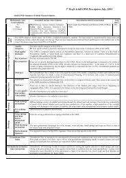
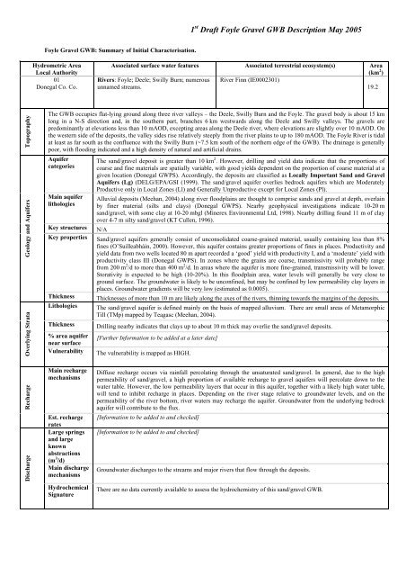
1 st Draft <strong>Foyle</strong> <strong>Gravel</strong> GWB Description May 2005<strong>Foyle</strong> <strong>Gravel</strong> GWB: Summary <strong>of</strong> Initial Characterisation.Hydrometric AreaLocal Authority01Donegal Co. Co.Associated surface water features Associated terrestrial ecosystem(s) Area(km 2 )Rivers: <strong>Foyle</strong>; Deele; Swilly Burn; numerous River Finn (IE0002301)unnamed streams.19.2TopographyGeology and AquifersOverlying StrataThe GWB occupies flat-lying ground along three river valleys – the Deele, Swilly Burn and the <strong>Foyle</strong>. The gravel body is about 15 kmlong in a N-S direction and, in the southern part, branches 6 km westwards along the Deele and Swilly valleys. The gravels arepredominantly at elevations less than 10 mAOD, excepting areas along the Deele river, where elevations are slightly over 10 mAOD. Onthe western side <strong>of</strong> the deposits, the valley sides rise relatively steeply from the river plains to up to 180 mAOD. The <strong>Foyle</strong> River is tidalat least as far south as the confluence with the Swilly Burn (~7.5 km south <strong>of</strong> the northern edge <strong>of</strong> the GWB). The drainage is generallypoor, with flooding indicated and a high density <strong>of</strong> natural and artificial drains.AquifercategoriesMain aquiferlithologiesThe sand/gravel deposit is greater than 10 km 2 . However, drilling and yield data indicate that the proportions <strong>of</strong>coarse and fine materials are spatially variable, with good yields dependent on the proportion <strong>of</strong> coarse material at agiven location (Donegal GWPS). Accordingly, the deposits are classified as Locally Important Sand and <strong>Gravel</strong>Aquifers (Lg) (DELG/EPA/GSI (1999). The sand/gravel aquifer overlies bedrock aquifers which are ModeratelyProductive only in Local Zones (Ll) and Generally Unproductive except for Local Zones (Pl).Alluvial deposits (Meehan, 2004) along river floodplains are thought to comprise sands and gravel at depth, overlainby finer material (silts and clays) (Donegal GWPS). Nearby geophysical investigations indicate 10-20 msand/gravel, with some clay at 10-20 mbgl (Minerex Environmental Ltd, 1998). Nearby drilling found 11 m <strong>of</strong> clayover 4-7 m silty sand/gravel (KT Cullen, 1996).Key structures N/AKey properties Sand/gravel aquifers generally consist <strong>of</strong> unconsolidated coarse-grained material, usually containing less than 8%fines (O’Suilleabháin, 2000). However, this aquifer contains greater proportions <strong>of</strong> fines in places. Productivity andyield data from two wells located 80 m apart recorded a ‘good’ yield with productivity I, and a ‘moderate’ yield withproductivity class III (Donegal GWPS). In zones where the grains are coarse, transmissivity will probably rangefrom 200 m 2 /d to more than 400 m 2 /d. In areas where the aquifer is more fine-grained, transmissivity will be lower.Storativity is expected to be high (10-20%). In this floodplain area, water levels will generally be very close toground surface. The groundwater is likely to be unconfined, but may be confined by low permeability clay layers inplaces. Groundwater gradients will be very low (estimated as 0.0005).ThicknessLithologiesThickness% area aquifernear surfaceVulnerabilityThicknesses <strong>of</strong> more than 10 m are likely along the axes <strong>of</strong> the rivers, thinning towards the margins <strong>of</strong> the deposits.The sand/gravel aquifer is defined mainly on the basis <strong>of</strong> mapped alluvium. There are small areas <strong>of</strong> MetamorphicTill (TMp) mapped by Teagasc (Meehan, 2004).Drilling nearby indicates that clays up to about 10 m thick may overlie the sand/gravel deposits.[Further Information to be added at a later date]The vulnerability is mapped as HIGH.RechargeDischargeMain rechargemechanismsEst. rechargeratesLarge springsand largeknownabstractions(m 3 /d)Main dischargemechanismsHydrochemicalSignatureDiffuse recharge occurs via rainfall percolating through the unsaturated sand/gravel. In general, due to the highpermeability <strong>of</strong> sand/gravel, a high proportion <strong>of</strong> available recharge to gravel aquifers will percolate down to thewater table. However, the low permeability layers that occur in this aquifer, together with a likely high water table,will tend to inhibit recharge in places. Depending on the river stage relative to groundwater levels, and on thepermeability <strong>of</strong> the river bottom, river waters may recharge the aquifer. Groundwater from the underlying bedrockaquifer will contribute to the flux.[Information to be added to and checked][Information to be added to and checked]Groundwater discharges to the streams and major rivers that flow through the deposits.There are no data currently available to assess the hydrochemistry <strong>of</strong> this sand/gravel GWB.
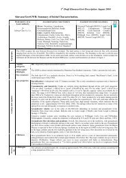
1 st Draft <strong>Foyle</strong> <strong>Gravel</strong> GWB Description May 2005Groundwater FlowPathsGroundwater & Surfacewater interactionsConceptual modelThe length <strong>of</strong> flow paths depend on the size and dimensions <strong>of</strong> the sand/gravel deposit, and also upon the spacing <strong>of</strong>internal groundwater divides and the distance between streams, if groundwater is discharging to them. In general,groundwater will flow at high angles to the Rivers Deele, Swilly Burn and <strong>Foyle</strong> and smaller streams, thus theflowpaths typically will be considerably less than about 500 m. However, where low permeability subsoils above thegravels confine groundwater locally, groundwater flowpaths may be longer. Flow direction in this case will beparallel to the river.In general groundwater from sand/gravel deposits located in river valleys discharges to the streams/rivers flowingthrough the valley. The hydraulic connection between the groundwater in the aquifer and the stream is expected tobe variable due to spatially varying subsoil permeabilities. Water may be able move into and out <strong>of</strong> the aquifer fromthe river in certain locations depending on the river stages and permeability <strong>of</strong> the subsoils.• The GWB consists <strong>of</strong> sand/gravel deposits lying along the River <strong>Foyle</strong> north <strong>of</strong> Strabane, and along E-W trending, steep-sided rivervalleys that feed into the River <strong>Foyle</strong>.• The deposits are located beneath river floodplains, and are situated at elevations less than 10 mAOD. The surface drainage iswestwards and northwards. Surface drainage is poor, and the areas are prone to flooding. The <strong>Foyle</strong> River is tidal at least as farsouth as the confluence with the Swilly Burn (~7.5 km south <strong>of</strong> the northern edge <strong>of</strong> the GWB).• The aquifers are comprised <strong>of</strong> alluvial deposits, which drilling data indicate are comprised <strong>of</strong> sands/gravels with clay layers.• Transmissivity is expected to be 400 m 2 /d or less, depending on the grain size and sorting <strong>of</strong> the deposits. The grain size <strong>of</strong> thedeposits varies laterally as well as vertically.• The sand/gravel aquifers are likely to be greater than 10 m thick, excepting at their margins.• Ground level data and surface drainage indications suggest that groundwater gradients are very low (estimated as 0.0005).• Diffuse recharge occurs via rainfall percolating through the unsaturated sand/gravel. Recharge is likely to be inhibited by the highgroundwater levels and, in places, by low permeability deposits overlying the sands/gravels. Groundwater will also flow laterallyinto the deposits from the underlying bedrock aquifers.• Groundwater discharges to the rivers and streams that flow through the deposits.• Due to the geometry <strong>of</strong> the deposits, groundwater flow paths are likely to be less than 500 m in areas where groundwater isunconfined. In areas where the hydraulic connection between ground and surface waters is low due to low permeability deposits,groundwater flow paths are likely to be longer; they will also be parallel rather than at an angle to the rivers.Attachments Figure 1.Instrumentation Stream gauges: none.EPA Water Level Monitoring boreholes: none.EPA Representative Monitoring points: none.InformationSourcesDisclaimerDELG/EPA/GSI (1999) Groundwater Protection Schemes. Department <strong>of</strong> the Environment and Local Government,Environmental Protection Agency and <strong>Geological</strong> <strong>Survey</strong> <strong>of</strong> <strong>Ireland</strong>.K.T. Cullen & Co. Ltd. (1996). Report on a Trial Well Drilling and Testing Programme at Lagan, East Donegal. Preparedat the Request <strong>of</strong>: Donegal County Council. No. 813.Lee, M. and Fitzsimons, V. (2004) County Donegal Groundwater Protection Scheme. Volume 1 Main Report, Draft, July2004. 58 pp. <strong>Geological</strong> <strong>Survey</strong> <strong>of</strong> <strong>Ireland</strong>.Meehan, R.T., (2004) Subsoils Map for County Donegal. Map produced as part <strong>of</strong> EPA Soil and Subsoil Mapping Project(formerly FIPS-IFS). Teagasc, Kinsealy.Minerex Environmental Ltd (1998). Report on Lund Imaging Geophysics. Letter to P. Barr, Eurocement, Lifford.O’ Riain, G., (2004). Water Dependent Ecosystems and Subtypes Draft Report. WFD Support Projects. CompassInformatics in association with National Wildlife and Parks Service (DEHLG).O’Suilleabháin, C., (2000). Assessing the boundary between high and moderately permeable subsoils. Unpublished MSc.,University <strong>of</strong> Dublin. Department <strong>of</strong> Civil, Structural and Environmental Engineering, Trinity College Dublin.Note that all calculations and interpretations presented in this report represent estimations based on the informationsources described above and established hydrogeological formulae
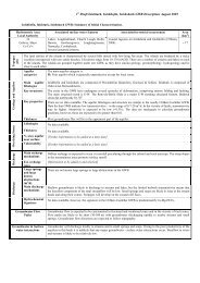
Figure 1 Location and extent <strong>of</strong> <strong>Foyle</strong> <strong>Gravel</strong>1 st Draft <strong>Foyle</strong> <strong>Gravel</strong> GWB Description May 2005