Create successful ePaper yourself
Turn your PDF publications into a flip-book with our unique Google optimized e-Paper software.
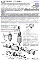
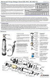
<strong>Gopher</strong> 40 kpsi Self-Rotary SwivelDescription:Maintenance:6. Stack the Seal Retainer (BC520) around the Carbide Seat.7. Stack the Seat Face (BC 506).8. Slip the Cartridge Housing(BC 407) over entire stack and pickup the whole assembly with mandrelstill inserted.9. Insert O-Ring (BJ 072) into slotin Cartridge Housing to capture thecomponents. Be sure to check thatthe entire O-Ring is seated properly.Seal & Seat DetailBC 511CarbideSeatchamferBC 512-OH.P. Seal*Blow out all water with compressed air before storing tool!BJ 417O-RingBJ 072O-RingBC 407CartridgeHousingBC 506Seat FaceBC 520Seal RetainerBC 511Carbide SeatBC 512-OH.P. SealBC 524CompressionSpringBC 522-001Inlet Seatinternal cone endBJ 072O-RingBC 414MandrelBC 512-OH.P. SealBC 524Compression SpringBC 522-001Inlet SeatBC 511Carbide SeatBC 520Seal RetainerBC 506Seat Face(<strong>GO</strong>-<strong>H9</strong>-C)The <strong>Gopher</strong> <strong>H9</strong>-C is a self-rotating swivel designed for tube and pipe cleaning. It has an outside diameter of 1.62inches (42mm). The tool can be used at operating pressures up to 40,000 psi (2800 bar) and flow rates from 4 to 10gpm. The tool has a 9/16 high pressure cone and thread female inlet, with an easily replaced seal cartridge assembly.The swivel is filled with 10W-40 for lubrication; it also affects rotation speed. The swivel rotation can be slowed with aheavier oil such as 80W-90.Two standard heads are available for the <strong>Gopher</strong>; both have 1/4-28 threads for sapphire nozzles. When installingnozzles, use Blue Goop antiseize for best results. The Polisher Head (<strong>GO</strong> 342) is intended for removing scale. TheUnplugger Head (<strong>GO</strong> 343) is intended for use in plugged tubes. Stamped on the head is an R18 or R08; this is theoffset that makes the head rotate. If less flow is used than the range shown, the swivel will not rotate. If more flow isused than shown in the range, the tool will rotate too fast, damaging the bearings and using up the high pressure seal.Consult the table forthe correct flow range forOffset R18 R14 R08each head offset.Flow (Polisher) - 3.7 to 6.6 gpm 7 to 10 gpmFlow (Unplugger) 4 to 7 gpm - 7.1 to 10 gpmDetermine where the jetsshould go in the head. The thrust of the jets can be used to pull the tool thru a pipe or tube. Little or no pull isneeded for cleaning vertically downward, but more pull is needed if cleaning horizontally or climbing upward.The jet sizes should be selected based on proportioning the total flow rate between the forward and backwardjets to achieve the pulling force needed, but still applying enough power to the material being removed ahead of the tool.Operation:10. Remove the Mandrel.FT 110SyringeBJ 417O-RingBC 505-SCartridge AssyFT 026PortScrewBC 407CartridgeHousingRJ 029Shaft SealBC 040O-RingTo replace the high pressure seal:1. Remove the O-Ring (BJ 417) from inlet port.It is easiest to push it upward from the roundweep hole.2. If necessary, use two picks inserted thruthe slots to pry the Cartridge Assy (BC 505-S)up and out of the Body.3. Turn the swivel inlet end up; insert a freshCartridge Assy into the inlet port and re-insertthe O-ring behind the Cartridge Assy to secureit in place.The <strong>GO</strong>-<strong>H9</strong>-C uses 10W-40 oil for lubrication andspeed control. It is recommended that a fullsyringe of fresh fluid be added tothe swivel afterevery 20 to 40 hours of operation.1. Remove the Port Screw (BJ 026)2. Thread the Syringe (BC 410) into the port.3. Squeeze fresh oil into the swivel; excess willcome out the slots.4. Remove Syringe and install Port Screw.BC 505-SCartridge Assy<strong>GO</strong> 402Inlet Nut<strong>GO</strong> 303BodyMT 010Shaft Seal3 Forward Ports2 Back Ports<strong>GO</strong> 025CollarFT 026Port ScrewUnplugger Head<strong>GO</strong> 343Make sure there is an operator controlled dump in the system, operated by the person closest to the cleaning job. Flush out the high pressure hoses before connecting<strong>Gopher</strong> to hose end or stinger. When pipe cleaning, it is recommended that the hose be marked a few feet from the end with a piece of tape so the operator knows whento stop on the way back out. When tube cleaning, a stinger is recommended; a stinger is a rigid piece of pipe or tubing used between the end of the hose and the nozzle.It is typically 2 feet in length, and is primarily a safety device for hand flex lancing. Install tool on hose, position it in a tube or the pipe while the pressure is being set. Thehigh pressure seal may leak initially; it should stop when pressure is increased and rotation begins. Close the dump and slowly bring up to pressure the first time, to makesure no nozzles are plugged and that the jet thrust is correct. The swivel should begin to slowly rotate. Once operating pressure is reached, feed the tool into the tube orpipe to begin the cleaning job. When using rotating nozzles in plugged tubes, the head must not be forced into the deposit, as this will stop the rotation of the tool andimpede the cutting ability. When the tool contacts the deposit, allow it to cut away the material and advance at it’s own rate. If it stops advancing, pull back slightly on thehose to pull the head slightly away from the deposit, in case it is being stopped from rotating by the deposit. This also allows the angled jets to attack the deposit atdifferent places. When polishing tubes with scale, it is possible to allow the nozzle to pass through the tube at incredibly fast rates; unless the deposit is very easy toremove, this will not completely remove the scale. The operator needs to be trained to feed the nozzle through the tube at a rate sufficient to clean the tube. Once thework is complete and the tool is disconnected from the hose, blow out all water to prolong the life of the tool. A small amount of oil can be blown into the inlet nut as well.Troubleshooting:SAPATENTS.COMHead will not rotate: First try rotating head by hand and see if it feels rough or gritty to turn. If it does, the tool must be disassembled and repaired. If the tool has justbeen repaired and the head starts to rotate but slows down and stops as pressure is increased, the front bearings (RJ 007) are installed backwards. If the tool feels okay,check to see if any nozzles are plugged; even if a nozzle is only partially blocked it can keep the head from rotating. Nozzles must be removed from the head to properlyclean them. Refer to the above description about the head offset and double check the nozzle sizes to make sure they are correct for the expected flow rate.Head spins too fast: if the swivel is low on oil, or the oil has water in it. Add a full syringe of oil; check that the shaft seals are still good and will keep the fluid fromleaking out. Finally, if it is rotating extremely fast and failing high pressure seals in a few minutes, the spring that controls the speed is broken or disconnected.Seal Leak: The seal may leak initially up to several thousand psi, but should pop closed as pressure is increased. If operating pressure is reached and the seal is leakingcontinuously, the cartridge should be replaced. Refer to the maintenance below. If the cartridge is replaced and the tool still leaks, inspect the shaft end face for damagesuch as dents, nicks or erosion.Seals wear out quickly: Remove and inspect the cartridge parts. The carbide seat should be checked for chips or erosion marks on it. When the life of the high pressureseal becomes noticeably less, the seal retainer needs to be replaced. Also replace the carbide seat if it has not been replaced with each seal change.To assemble theCartridge Assy:1. Place Mandrel (BC 414)on a flat surface.2. Stack the Inlet Seat (BC 522-001) with the internal cone at thebottom onto the Mandrel.3. Insert Compression Spring (BC524) into bore of Inlet Seat.4. Insert H.P. Seal (BC 512-O) intobore of Inlet Seat making sure theend with the O-Ring and sealsupport goes in first. (see detail)5. Stack the Carbide Seat (BC 511)making sure the chamfered end isagainst the H.P. Seal. (see detail)Polisher Head<strong>GO</strong> 3423 Ports at 80°3 Ports at 100°RJ 008O-RingBC 009BearingBC 031Backup RingBC 222WasherBC 220WeightsBC 315SpringBC 230Sleeve<strong>GO</strong> 401ShaftRJ 007Bearing (2)®© 2012 StoneAge , All Rights Reserved
<strong>Gopher</strong> 40 kpsi Self-Rotary Swivel (<strong>GO</strong>-<strong>H9</strong>-C)Disassembly:SAPATENTS.COM1. Remove O-Ring (BJ 417) from Inlet Nut.Pry out the high pressure seal CartridgeAssy (BC 505-S) as explained in theMaintenance Section.2. Remove the Head (not shown) and theCollar (<strong>GO</strong> 025) from the Shaft.BJ 417O-RingBC 505-SCartridge Assy<strong>GO</strong> 402Inlet NutBC 230Sleeve3. Unscrew the Inlet Nut (<strong>GO</strong> 402)from the Body (<strong>GO</strong> 303).4. Push Shaft (<strong>GO</strong> 401) and allattached parts up and out of the Body.5. Slide the Sleeve (BC 230) up andoff of the shaft.6. If the Shaft Seals (MT 010, RJ 029)in the Inlet Nut and Body are damaged,pry them out and replace them.BC 009BearingBC 222WasherBC 220WeightsBC 315Spring<strong>GO</strong> 401Shaft7. Remove the Bearing (BC 009) fromthe end of the Shaft (or from the Inlet Nut).8. Remove the Washer (BC 222) fromthe shaft.9. Unhook the Spring (BC 315) from thehole in the shaft; remove the Weights (BC 220)and Spring (BC 315) from the shaft. Leavethe weights together.10. Remove the two Bearings (RJ 007).<strong>GO</strong> 401Shaft<strong>GO</strong> 025Collar11. Inspect the O-Ring (BC 040) and theBackup Ring (BC 031) on the shaft end.Replace them if they are cut or damaged.<strong>GO</strong> 303BodyBC 031Backup RingBC 040O-RingRJ 007BearingsAssembly:1. Install O-Ring (RJ 008) over thethreads of the Inlet Nut (<strong>GO</strong> 402).Install Shaft Seal (MT 010) into theInlet Nut; the lip with the spring facesdown in this view.2. install Shaft Seal (RJ 029) intoBody (<strong>GO</strong> 303); the lip of the sealwith the spring faces up in this view.Apply Armour All or grease to thelips of the seals.MT 010Shaft Seallip of sealwith springRJ 008O-RingBC 009BearingBC 222WasherBC 220WeightsBC 315Spring3. install Bearings (RJ 007)on Shaft (<strong>GO</strong> 401); these arethrust bearings and must beinstalled with the wide innerraces facing toward shoulderon shaft.4. Install Backup Ring(BC 031) and O-Ring(BC 040) on shaft end.5. Insert end of Spring(BC 315) into hole in Weights(BC 220), then slide weightsand spring onto shaft andinsert other spring end intohole in shaft.6. Place Washer (BC 222)on top of weights with thechamfered side facingtoward the weights.<strong>GO</strong> 402Inlet Nut10. Install Collar (<strong>GO</strong> 025) ontoend of shaft.11. Install the high pressure sealCartridge Assy as described inthe Maintenance Section.12. Fill the swivel with oil asshown in the Maintenane Section.Install the Port Screw (FT 026).BJ 417O-RingBC 505-SCartridgeAssy<strong>GO</strong> 402Inlet Nut<strong>GO</strong> 401Shaft7. Slide Bearing (BC 009)onto shaft. Slide Sleeve(BC 230) over the assembly.8. Carefully insert shaftassembly into the Body(<strong>GO</strong> 303).BC 230Sleevelip of sealwith springRJ 029Shaft Seal<strong>GO</strong> 303BodyBC 031Backup RingBC 040O-Ringwide inner raceRJ 007Bearingwide inner race9. Thread Inlet Nut intoBody; tighten to 40 ft-lb.<strong>GO</strong> 025Collar<strong>GO</strong> 303BodyFT 026Port ScrewRJ 007Bearing®© 2012 StoneAge , All Rights Reserved