“Sized-up” QuickTerm™ Termination Kit - Pentair Thermal Controls
“Sized-up” QuickTerm™ Termination Kit - Pentair Thermal Controls
“Sized-up” QuickTerm™ Termination Kit - Pentair Thermal Controls

You also want an ePaper? Increase the reach of your titles
YUMPU automatically turns print PDFs into web optimized ePapers that Google loves.
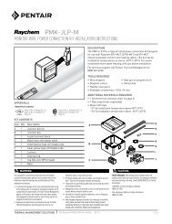
1Note: The minimum installation temperature for thisQuickTerm termination kit is 32°F (0°C).• With a hacksaw, cut the end of the MI cable square and filethe end smooth.• Identify the compression connector supplied with thetermination kit. Locate the corresponding compressionconnector part number in the Table on page 3 and mark theMI cable sheath at length “L” shown in the table. This is thelength of sheath to remove.Using Sheathmaster sheath stripping tool• If using the Sheathmaster sheath stripping tool, place asecond mark 1 in (2.5 cm) behind this first mark as shown.If using the Ratchet Type stripping tool, place the secondmark 1-1/2 in (3.8 cm) behind the first mark. The sheath willonly be stripped back to the first mark exposing the solidconductor. The second mark from the end is used to positionthe handvise for final stripping.• For details on using the Sheathmaster tool, refer toinstruction H59039 supplied with the tool; for the RatchetType tool, refer to instruction H57842 supplied with the tool.An alternate method of stripping the cable sheath using atubing cutter and side cutters is shown in Appendix B.Using Ratchet Type stripping tool1 in (2.5 cm) required forSheathmaster sheathstripping tool (sheath willnot be removed fromthis section)1 in(2.5 cm)Identify connectorsupplied with kit andmark cable sheath atlength “L” shownin Table1-1/2 in (3.8 cm) required forRatchet Type Stripping Tool(sheath will not be removedfrom this section)1-1/2 in(3.8 cm)Identify connectorsupplied with kit andmark cable sheath atlength “L” shownin TableSecondmarkFirstmark“L”SecondmarkFirstmark“L”Sheathmaster toolRatchet Typestripping tool2 3• Place the brass gland connector on to the cable. Thegland connector is made up of three parts: the gland nut,the compression sleeve and the gland body. It should beplaced on to the cable with all three pieces assembled.• Grip the cable with the Handvise.• Using the sheath stripping tool (Ratchet Type tool shown),begin stripping the copper sheath back towards the firstmark.Gland nutCompression sleeveGland bodyGland connectorCopper sheathMI cableCoppercuttingsTHERMAL MANAGEMENT SOLUTIONS EN-PyrotenaxQuickTermSizedUp-IM-H58264 11/13 2 / 8
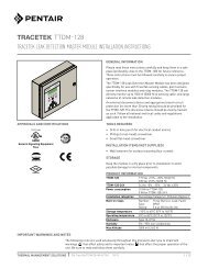
Guide for end-to-end splicing of 90°C, 600 volt insulated stranded copper conductor tail to MI solid copper conductorCable referencenumberMI cable size(AWG/kcmil)Compressionconnectoridentification90°C insulatedstranded conductorrequiredLength “L” of MIsheath to stripMI sheathstripping toolCompressiontools (seeNotes)Die colorNumber of crimpsSystem 18501/6-340 6 A8212 2 AWG 2-3/4 in (7.0 cm) Sheathmaster Die Type Brown 2 21/4-402 4 A8211 1/0 AWG 2-3/4 in (7.0 cm) " Die Type Pink 2 21/3-449 3 A8210 2/0 AWG 2-7/8 in (7.3 cm) " Die Type Black 2 21/2-449 2 A8209 3/0 AWG 2-7/8 in (7.3 cm) " Die Type Orange 2 21/1-496 1 A8208 4/0 AWG 2-7/8 in (7.3 cm) " Die Type Purple 1 11/1/0-512 1/0 A8207 4/0 AWG 2-7/8 in (7.3 cm) " Die Type Purple 1 11/2/0-580 2/0 A8206 250 kcmil 3 in (7.6 cm) " Die Type Yellow 2 21/3/0-621 3/0 A8205 350 kcmil 3 in (7.6 cm) " Die Type Red 1 11/4/0-684 4/0 A8204 500 kcmil 3-1/4 in (8.3 cm) " Die Type Brown 1 11/250-746 250 A8203 500 kcmil 3-1/4 in (8.3 cm) " Die Type Brown 1 1A8213 600 kcmil 3-1/4 in (8.3 cm) " Die Type Green 1 11/350-834 350 A8179 500 kcmil 3-1/4 in (8.3 cm)Ratchet Typestripping toolDie Type Brown 2 2A8189 750 kcmil 3-1/2 in (8.9 cm) " Die Type Black 3 31/500-1000 500 A8181 750 kcmil 3-1/2 in (8.9 cm) " Die Type Black 3 3Notes:1. Connector part numbers for 6 AWG to 250 kcmil cables must be crimped using Ilsco ILC-12, ILC-12-N, ILC-12H or ILC-12H-N die type hydraulic tools.2. Connector part numbers for 350 kcmil and 500 kcmil cables must be crimped using Ilsco ILC-12, ILC-12-N, ILC-12H, ILC-12H-N, ILC-14 or ILC-14H die typehydraulic tools.SolidendStrandedend45• For final stripping, grip the cable with the Handvise at thesecond mark. When the stripping tool touches the edgeof the Handvise, it will stop and make a clean cut on thecable sheath at the first mark. At this point, the correctlength of solid conductor will have been exposed.Grip cable sheath atsecond mark with Handvise1 in (2.5 cm) or 1-1/2 in (3.8 cm)depending on stripping tool used“L”• Clean the conductor with a clean, dry, rag or cloth toremove loose powder from the conductor. Next, polishall around entire length of solid conductor and 2 in (5.0cm) of sheath behind the conductor with emery paper toachieve a clean surface.• Visually inspect the magnesium oxide insulation at theface of the cable for traces of copper filings and burrs andif present, gently remove with a pick.Note: When cleaning the conductor with the rag andemery paper and if it is necessary to use a pick to removecopper filings from the face of the cable, do not removemore powder from the face of the cable than is necessary.Note: Do not blow out copper filings that may be presentin the MgO powder as this can introduce moisture intothe end of the cable, resulting in decreased insulationresistance.SecondmarkHandviseSolidconductor2 in(5.0 cm)“L”PickTHERMAL MANAGEMENT SOLUTIONS EN-PyrotenaxQuickTermSizedUp-IM-H58264 11/133 / 8
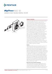
6• Using a 500 Vdc megohmmeter, check the insulationresistance (IR) of the cable between conductor and sheathto ensure it is free of grounds and shorts. The other cableend must also be free of grounds and shorts and must besealed. See Appendix A for detailed test procedure and IRtest criteria. Once IR readings are satisfactory, immediatelycomplete Step 7 to seal the end of the MI cable. A delay willcause the IR to drop and the cable must be retested priorto sealing the end.Note: If neither cable end has yet been terminated and IRreadings are low, dry out both ends following the procedurein Appendix C or cut off shorted end and re-test. Apply atemporary moisture resistant seal, such as hot melt glue oradhesive lined heat-shrinkable tubing, to opposite cable endto prevent moisture absorption.50010001500200025007• Apply tape seal to MI cable and ensure that you tape alongthe sheath and solid conductor as shown. Stretch the sealingtape to about 3 times its length (or about half of the originalwidth), just short of the breaking point.• Beginning on the cable sheath and using half-laps, wind thetape under tension, taping 1-1/2 in to 1-3/4 in (3.8 cm to 4.5cm) along the cable sheath and 1-1/2 in to 1-3/4 in (3.8 cm to4.5 cm) along the solid conductor.• Reverse the direction and wind the tape back along theconductor and 1-1/2 in to 1-3/4 in (3.8 cm to 4.5 cm) of cableBegin tape seal here and wrap backand forth three times as shown belowsheath (over the tape just applied).• Finally, reverse the direction once again and wind the tapeback along the sheath and 1-1/2 in to 1-3/4 in (3.8 cm to 4.5cm) of conductor (again, over the tape just applied). Maintainhalf-laps and stretch tape as described above while windingalong sheath and conductor. Tear off excess tape. The tapewill bond to itself in a short time.Important: Use only the self-amalgamating tape supplied by<strong>Pentair</strong> <strong>Thermal</strong> Management to seal the end of the MI cable....then back alongconductor and sheath...SheathConductor1-1/2 in to 1-3/4 in(3.8 cm to 4.5 cm)Wrap tape seal alongsheath and conductor......and once again back alongsheath and conductor1-1/2 in to 1-3/4 in 1-1/2 in to 1-3/4 in(3.8 cm to 4.5 cm) (3.8 cm to 4.5 cm)THERMAL MANAGEMENT SOLUTIONS EN-PyrotenaxQuickTermSizedUp-IM-H58264 11/13 4 / 8
8 9• Once the tape seal is completed to this point, the end ofthe MI cable should appear as shown.Self-amalgamating tape seal• Identify the compression connector. The solid MIconductor is inserted into the smaller end of theconnector (with the copper reducer sleeve). The strandedconductor tail must be inserted into the larger end.• Strip just enough insulation from the appropriate AWGsize, 90°C, 600 V stranded conductor tail to fit to thecenter-stop in the compression connector (see Table orthe green card included in the termination kit for furtherdetails on the size of stranded conductor tail required).• Crimp the connector to the stranded conductor tail usingthe required number of crimps and an approved crimpingtool (see Table on page 3 for details). Where multiplecrimps are required, make the outside crimp first andwork towards the middle of the connector.Important: See Table on page 3 for approved crimpingtools to be used with the QuickTerm compression connectors.Copper sheathMI cableSolidconductorCompressionconnector(supplied in kit)Crimp to “sized-<strong>up”</strong> strandedconductor tail using requirednumber of crimps and approvedcrimping tool (see Table)<strong>“Sized</strong>-<strong>up”</strong> strandedcopper conductor tail(supplied by installer)10• Place the adhesive lined heat shrinkable tubing (suppliedwith termination kit) on to the MI cable.• Insert the solid MI conductor into the smaller end of thecompression connector.• Crimp the connector to the solid conductor using therequired number of crimps and an approved crimping tool(see Table on page 3 for details). Where multiple crimpsare required, make the outside crimp first and worktowards the middle of the connector. The solid conductorto stranded conductor joint should appear as shown.11• Prior to sealing the entire joint with the heat-shrinkabletubing, remove all sharp edges from the compressionconnector with a flat file.• Place the heat-shrinkable tubing over the joint so that itcompletely covers the tape seal and compression connectorand overlaps the MI cable sheath and the insulation on thestranded conductor tail by at least 1/2 in (1.3 cm).• Shrink in place with a heat gun or propane torch beingcareful not to damage the heat-shrinkable tubing. Whenusing a propane torch, take care not to burn the heatshrinkabletubing.Crimp to solid conductorusing required number ofcrimps and approvedcrimping tool (see Table)Heat-shrinkable tubing overMI cable sheath, tape seal,compression connector andstranded conductor tailHeat shrinkable tubingMI cableInsulatedstrandedconductor tailSized-up strandedconductor tailOverlap copper sheathand cable jacket by1/2 in (1.3 cm) minimumTHERMAL MANAGEMENT SOLUTIONS EN-PyrotenaxQuickTermSizedUp-IM-H58264 11/135 / 8
12• Check IR once more from stranded conductor tail to MIcable sheath to ensure that the cable has been properlysealed and IR is satisfactory. If the IR does not meet thevalues under Test Criteria in Appendix A, the terminationmust be removed and remade after completing the“drying out” procedure outlined in Appendix C.MI cable5001000150020002500Heat-shrinkabletubingStrandedwire tailAppendix A: Insulation Resistance (IR) TestTest Equipment500 Vdc MegohmmeterIR TestingIR testing is conducted using a megohmmeter and tests theintegrity of the cable between the conductor and the coppersheath.Test CriteriaWhen received:• Check cable on reel. Note that ends may need to be preparedto allow insulation resistance (IR) readings to be taken. IRreadings must not be less than 200 MΩ under any conditions.After installing termination kit:• In a warm, dry environment, IR readings should be 200 MΩ orhigher.• In an outdoor environment or indoors in wet or humid conditions,IR readings should all be above 100 MΩ.• Similar cables exposed to similar conditions should all have IRreadings in the same general range. Where a large differencein readings is encountered, high readings can be accepted;low readings (below 100 MΩ) should be checked as describedbelow.Note: Under some installation conditions it may not be possibleto obtain IR readings above 100 MΩ. If IR readings arebetween 25 MΩ and 100 MΩ, wait 24 hours and recheck the IRusing the same equipment. If the IR reading has not decreased,the termination is good - a constant low IR reading can resultfrom moisture entrained in the cable while making a good seal;this moisture will not increase. If the IR reading has decreased,the cable must be re-terminated - a low IR reading can resultfrom a poorly made seal which will allow continuing moistureingress, requiring that the termination be redone.If the IR reading is less than 25 MΩ, the cable must be re-terminatedfollowing the “drying out” procedure in Appendix C.Test Procedure1. Set megohmmeter test voltage at 0 Vdc or off.2. Connect the positive (+) (earth) lead to the cable sheath.3. Connect the negative (–) (line) lead to the conductor.4. Turn on the megohmmeter and set the voltage to 500 Vdc;apply the voltage for one minute. Meter needle should stopmoving. Rapid deflection indicates a short. Note the insulationresistance value. It should correspond to the values shownunder Test Criteria.5. Turn off the megohmmeter.WARNING: Shock Hazard. The MI cable can store a largeelectrical charge after the insulation resistance test isperformed. To prevent personal injury from electricalshock, fully discharge the cable prior to disconnecting themegohmmeter. Many meters will discharge automatically.However, it may be necessary to short the cable leads.Contact your supervisor or the instrument manufacturer toverify the safest practice.6. Testing is complete. If the megohmmeter does not self-discharge,discharge phase connection to ground with a suitablegrounding rod. Disconnect the megohmmeter.5001000150020002500THERMAL MANAGEMENT SOLUTIONS EN-PyrotenaxQuickTermSizedUp-IM-H58264 11/13 6 / 8
Appendix B: Stripping Pyrotenax Copper Sheath MI CableUsing diagonal cuttersMeasure, from cable end, length of cable sheath to strip andmark sheath with marking pen. Use a tube cutter to scorearound the sheath at the mark. This will cause the sheathto peel away at the score providing a smooth end when thesheath is stripped. The correct depth of score is half the thicknessof the sheath.Do not cut completely through the cable sheath as this willcause the sheath to curve inwards toward the conductor(s).Continue removing the sheath to the score mark. When aboutto break into the score, bring side cutters to right angle withcable. Finish off with point of side cutters held parallel to thecable. The sheath will peel away leaving a clean cut when thescore mark is reached.Mark onSheathLength “L” of MIcable sheath to stripThe cable sheath is correctly stripped, with the sheath flaredslightly outwards, as shown in (a).In (b) the sheath is neither flared outwards nor beveledinwards, but is acceptable.Ensure that the sheath is not curved or beveled inward asshown in (c). This will occur if the score made with the tubecutter is too deep. In this case, remove a further 1/4 in (6 mm)of sheath. Cable is now ready to be sealed.Hold the cable with the handvise behind the score on thesheath. Grip the edge of the sheath between the jaws of theside cutters and twist clockwise (twist counter-clockwise if lefthanded),then take a new grip and rotate through a small angle.(a)Preferred(b)Acceptable(c)UnacceptableContinue this motion in a series of short “rips”, keeping theside cutters at about 45° to the line of the cable, removingsheath spirally. Remove compacted powder insulation toexpose conductors.ScoreTHERMAL MANAGEMENT SOLUTIONS EN-PyrotenaxQuickTermSizedUp-IM-H58264 11/137 / 8
Appendix C: Improving Insulation ResistanceTo maintain the high performance of MI cable, the cable mustbe properly stored and the ends must remain sealed.Damaged terminations or heat-shrinkable end caps that aredamaged, missing, or removed will cause the magnesium oxideinsulation (white powder) to absorb moisture, resulting in low IRreadings. The cable must be “heated out” to remove the moistureand bring the IR back to an acceptable level. Drying out theMI cable to remove any moisture will normally be unnecessaryproviding the termination seal is completed within a few minutesof removing the sheath.If moisture is found in the cable when checking IR, it may beremoved using one of the following methods:1. If excess cable is available, 6 to 12 in (15 to 30 cm) of cablemay be removed from the end before sealing the cable.2. Apply heat to the cable following the procedure below.Note: Moisture will not normally penetrate more than 12in (30 cm) into the cable.If moisture is detected in the cable, use an oxy-acetylene ormapp gas torch with a large flame and “heat out” the cablebeginning 12 in (30 cm) back from the end. Gradually move theflame toward and past the cable end. Pyrotenax copper sheathcables should be heated to a bluish-gray color. Take care not tooverheat any one area of the cable sheath as this could damagethe cable.Use a short sweeping motion of the torch and heat about 2 in (5cm) of cable at a time, repeating 4 to 5 times.Move the flame towards the cable end as shown. Do not sweepthe flame in the opposite direction as this will drive the moistureinto the cable.2 in (5 cm)Repeat 4 to 5 timesGradually move the flame toward the end while maintaining theshort sweeping motion of the torch. If you heat toward the cableend too quickly you may skip over the moisture and drive it furtherback into the cable.Repeat 4 to 5 times2 in (5 cm)It may be necessary to repeat the above procedure severaltimes to completely remove all moisture from the cable. Allowthe cable to cool before repeating. On completion, check IR witha 500-V insulation tester (Megohmmeter).WWW. PENTAIRTHERMAL.COMNORTH AMERICATel: +1.800.545.6258Fax: +1.800.527.5703Tel: +1.650.216.1526Fax: +1.650.474.7711thermal.info@pentair.comEurope, Middle East, AfricaTel: +32.16.213.511Fax: +32.16.213.603thermal.info@pentair.comAsia PacificTel: +86.21.2412.1688Fax: +86.21.5426.2917cn.thermal.info@pentair.comLatin AmericaTel: +1.713.868.4800Fax: +1.713.868.2333thermal.info@pentair.com<strong>Pentair</strong>, Pyrotenax, QuickTerm and Sheathmaster are owned by <strong>Pentair</strong> or its global affiliates. All other trademarks are the property of their respectiveowners. <strong>Pentair</strong> reserves the right to change specifications without prior notice.© 2008-2013 <strong>Pentair</strong>.THERMAL MANAGEMENT SOLUTIONS EN-PyrotenaxQuickTermSizedUp-IM-H58264 11/138 / 8