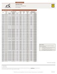
INSTALLATION INSTRUCTIONS OF BAY/BOW FRAME ... - Pella.com
INSTALLATION INSTRUCTIONS OF BAY/BOW FRAME ... - Pella.com
INSTALLATION INSTRUCTIONS OF BAY/BOW FRAME ... - Pella.com

You also want an ePaper? Increase the reach of your titles
YUMPU automatically turns print PDFs into web optimized ePapers that Google loves.
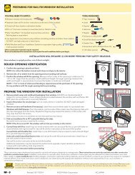
1 <strong>BAY</strong>/<strong>BOW</strong> <strong>FRAME</strong> PREPARATION (CONTINUED)G. Remove the ”T“ nuts from the cable hardware package.Using a hammer pound the ”T“ nut to seat it into the top ofthe frame head board at the pre-drilled hole location abovethe mullion joint. Repeat placement on other side.H. Insert the non-threaded end of the cable into the bottomcable support hole. Thread the cable through the bay framemullion and out the top support hole. The threaded end ofthe prepared cable with the washer and nut will stop againstthe bottom side of the bay frame. Repeat procedure for theother side.I. Tape the ends of the cables to the top of the bay/bowframe to keep them in place during installation.J. Tip the bay/bow frame up so the head board is up and the seat board is down.K. Remove the black plastic edging. Remove all of the attachment staples from the outsideedges around the perimeter of the frame.2 OPENING PREPARATIONA. If replacement application, remove the existing window. Clean the opening of anydirt, debris or excess old paint before proceeding. Remove siding as needed to makesure there is a minimum of 1-3/4" of the sheathing exposed below the bottom of therough opening for the bay/bow frame to be properly installed against the sheathing.CAUTION: Many windows in older homes are painted with lead-based paint. Removalof old windows may disturb this paint. Proper precautions must be taken to minimizeexposure to dust and debris. Consult state or local authorities for more information.B. Inspect the opening and repair or replace any defective or rotted wood parts.C. Confirm the opening is plumb and level.Note: It is critical the bottom is level.D. If new construction, cut the water resistivebarrier. Fold the flaps into the opening and stapleto the inside wall.
2 OPENING PREPARATION (CONTINUED)E. Apply sill flashing tape #1 (wood construction only). Cut apiece of flashing tape 12" longer than the opening. Apply at thebottom of the opening overlapping as shown so it overhangs 1"to the exterior and extends 6" up the side and up to the exterioredge of the opening.Note: The tape is cut 12" longer than the width so it willextend 6" up each side of the opening.F. Tab the sill flashing tape and fold (if tape #1 overhangs to theexterior). Cut 1" wide tabs at each corner (1/2" from each side ofthe corner). Fold tape to the exterior and press firmly to adhere itto the water resistive barrier.2F1"1/2"1/2"6"2EFlashing tapeoverhanging 1”to the exterior.G. Apply sill flashing tape #2. Cut a piece of flashing tape 12"longer than the opening width. Apply at the bottom, overlappingtape #1 by at least 1". DO NOT allow the tape to extend past theinterior face of the opening.Note: The flashing tape may not fully cover theframing members.Note: If the bay window is to be installed usingany support walls in addition to the main roughopening in the building, be sure to apply flashing tape in thesame manner to those walls.H. Install and level sill shims. Place 1" wide by 1/4" thick shims onthe bottom of the opening 1/4" from each side. Keep shims back1/2" from interior face of bay/bow frame. Add shims as necessaryto ensure the sill is level. Once level, attach shims to preventmovement.2H3PREPARINGAND SETTINGTHE <strong>BAY</strong>/<strong>BOW</strong> <strong>FRAME</strong>TWO OR MORE PEOPLE WILL BE REQUIRED FOR THE FOLLOWING STEPS.A. Drill seven 1/8" diameter installation holes 1/2" from theinterior corner of the bay frame jamb where the frame jamband interior window pocket meet so the holes can be coveredby the jamb interior trim pieces. Holes should be placed 4"from each end and with the remaining five holes evenly spacedbetween.1/2"B. Drill 3/32" diameter installation holes 2" from the interioredges of the head and seat boards. Holes should be placed 4"from each end and no more than 18" on center.3A
3PREPARINGAND SETTINGTHE <strong>BAY</strong>/<strong>BOW</strong> <strong>FRAME</strong> (CONTINUED)C. Insert the bay/bow frame. Place the seat of the frame atthe bottom of the opening and slide the top into position.Tip the frame up so the interior edge is flush with theinterior wall. Center the frame between the sides of theopening to allow clearance for shimming.D. Place temporary bracingunder the seat of the windowto support the bay/bow framein a level position.E. Place a shim near the top of one jamb board of theframe, aligned with the top pre-drilled holes in thejamb board. Keep shims back 1/2" from interior faceof bay/bow frame. Use a level to ensure the jamb isplumb and partially insert a #10 x 3" flat head screw(not provided). Repeat for the other jamb.3EF. Continue placing shims at each pre-drilled installation screw hole in jamb boards asneeded to plumb and square the frame. Keep shims back 1/2" from interior face ofwindow. Check the frame for squareness by making sure the diagonal measurementfrom corner to corner is within 1/8" in both directions. Insert a #10 x 3" flat head screwinto each pre-drilled hole in the jamb boards. Finish inserting the top screw in eachjamb board.G. Place shims between the head and seat boards at each pre-drilled installation holeand install a #8 x 2-1/2" trim head screw in each hole.
Note: Common bay/bow frame installation conditions are shown in the diagrams below.Note: If additional coil wrapping (cladding) is to be installed to the bay frame, DO NOTuse mechanical fasteners to attach the cladding to the sill. The sill pan is beneath the sillcladding and attaching with fasteners will penetrate the sill pan and create a path forwater infiltration.
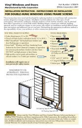
4PREPARING<strong>FRAME</strong> OPENINGS AND WINDOWSFOR <strong>INSTALLATION</strong> INTO <strong>FRAME</strong>Note: If Impervia Casements will be installed into the bay frame, go to Step 5 andprep by removing the casement interior frame covers before proceeding to Step 4A.Note: There are two methods of installation. (1) Bulbgasket in the exterior accessory groove or (2) Sealantaround the perimeter of the openings. If using sealantproceed to Step 4B.Note: In the sealant method the term "wetting out"means the adhesive flows and covers a surface tomaximize the contact area and the attractive forcesbetween the adhesive and bonding surface.A. Install the bulb gasket accessory kit (provided)into the exterior accessory groove of the head andboth jambs of each window to be installed into thebay/bow frame. Press the attachment leg of the bulbgasket into the accessory groove. The bulb gasket must beinstalled as one piece. DO NOT cut at the corners.B. Cover the seat board of the bay/bow frame withcardboard, plastic or a drop cloth to protect it fromscratches and sealant during the installation of windowsinto the frame.C. Measure the opening(s) to confirm they are square.If opening is out of square, adjust the temporaryexterior bracing.D. Dry fit the window to confirm proper fit and reveal inthe opening. Adjust the bracing as needed.E. Apply a 3/8" diameter bead of sealant across thesill approximately 1/2" from the back of the built-in sillpan at the sill. This will allow for the interior edge ofthe window sill to be set in the sealant bead when thewindow is installed. Place a dot of sealant in each cornerof the sill pan approximately 1" x 1". F. Apply a 1" diameter dot of sealant to each top cornerof the openings for the windows in the bay/bow frame.
4PREPARING<strong>FRAME</strong> OPENINGS AND WINDOWSFOR <strong>INSTALLATION</strong> INTO <strong>FRAME</strong> (CONTINUED)Note: Use opening preparation Step 4G only for unitsNOT using bulb gasket.G. Apply a minimum of 3/8" diameter of sealant on theexterior jamb and head stops of the bay/bow frame.Apply the sealant as close to the outside edge as possible.5 WINDOW PREPARATION (CASEMENT ONLY)The interior frame covers must beremoved to provide access to the predrilledframe screw installation holes.CAUTION: To Avoid Interior FrameCover Breakage - Carefully read andunderstand the following steps beforeproceeding with cover removal.The order of interior frame cover removalis indicated below. Use reverse order forre-installation of covers.A. Prepare the Window.1. Remove the screen and set aside.2. Use pliers to remove the plug(s) from the lockhandle location(s).3. Remove the construction handle tool from thehandle package.Construction Handle Tool may be used as alock handle or crank handle.
5WINDOWPREPARATION(CASEMENT ONLY) (CONTINUED)B. Remove Interior Frame Cover #1. If an Interior Frame Cover has a "Quick ReleaseBand" around the cover, pull the band to help remove the cover.The cover on vent units where the lock handle slot is located and the cover on theopposite frame side.1. Approximately 1" from the bottom(end) of the cover, insert the"hooked" end of the tool betweenthe cover and the sash.2. Rotate the tool toward the sash andcontinue to insert the tool past thespline hole up to the point where thebend in the tool is aligned with theedge of the cover.Note: When the tool is inserted with the bend alignedwith the cover edge there will be a slight gap betweenthe tool and the face of the sash.3. Push the tool flat against the sash(not a lot of force is needed) torelease the back cover barb from theframe kerf behind the cover. Whilekeeping tension on the tool, pull thetool away from the frame to startreleasing the cover barbs from theframe kerfs. 4. Rotate the cover end slightly toward the interior; when thecover begins to pull away from the frame, relocate the toolunder the cover towards the interior as shown, then pull thetool away from the frame to continue the release of the coverbarbs from the frame.5. Reposition the tool with the hookunder the front edge of the cover.Slide the tool over while pullingthe cover away from the frame. Thiswill release the flexible barbs onthe interior side of the cover, whichwill aid in cover removal. Continuesliding along the length of thecover while pulling it away from theframe until it is removed.6. Repeat Steps B1 thru B5 to remove the other Interior Frame Cover #1.If installing a casement or fixed unit less than 42" in width, go to Step 6“SETTING AND FASTENING THE WINDOW”. If installing units greater than42" in width, go to Step C.
5WINDOWPREPARATION(CASEMENT ONLY) (CONTINUED)C. Remove Interior Frame cover #3.The cover on vent units on the opposite frame side fromwhere the crank handle is located.For units greater than 42" in width.1. Start at one end of the cover and insert the tool betweenthe frame and cover as shown.2. Pull the tool away from the frame to start releasing thecover barbs from the frame kerfs.3. When the cover begins to pull away from the frame, grasp the cover and continue topull to release the barbs from the kerfs, removing the cover.TWO OR MORE PEOPLE ARE REQUIRED FOR THE FOLLOWING STEPS6 SETTING AND FASTENING THE WINDOWA. Insert the window and center it in the opening to allowclearance for shimming.Note: Use of a suction cup on the glass will assist inhandling the window.Note: Each existing window frame and wall depth willvary in different applications; therefore there is not astandard measurement for the overhang of the windowframe to the exterior or for the distance from the interiorface of the window to interior trim. When performingSteps 6B thru 6D, installing the frame screws, be sure tokeep the distance consistent all around the window.Note: On the exterior, there must be enough room forbacker rod and 3/8" sealant bead. B. Insert shims between the window andthe opening at the top two anchor holelocations in the window jambs.Note: Check the reveal so theinterior trim stops cover the interioraccessory grooves. Dry fit a piece oftrim to check reveal.Shim6B6C2-1/2" ScrewC. Fasten the window near the top of the opening by driving 2-1/2" long woodscrews through the top two holes at the jambs and into the opening sides.Note: Be sure to apply pressure against the window to fully <strong>com</strong>press thegasket against the stops in the bay/bow frame. Apply enough pressure tomake sure the gap between the window and the bay/bow frame at the headand jambs is < 3/16".Or if wet sealant was used around the perimeter of the opening, press thewindow against the sealant on the stops of the bay/bow frame until thesealant is fully wetted out. (Make sure the surfaces between contact points arefully covered with sealant).
6SETTINGAND FASTENINGTHE WINDOW (CONTINUED)D. Plumb and square the window. Insert shims between the window frame and therough opening at the anchor hole locations in the window frame.Note: Install the shims per Shim and Fastener Guide.DO NOT over shim. E. If additional installation holes are needed, drill a 3/16"installation hole through both the interior and exteriorwalls of the frame.F. Fasten the window in the opening by driving the 2-1/2"long screws through each pre-drilled hole in the window frame, through the shims andinto the rough opening.Note: Drive screws per the Casement Shim Fastener Guide.G. Insert the construction handle into the lock lever location and unlock the window.Remove the handle. Place the construction crank handle over the roto operator stud.Open and close each sash to verify the smooth operation and alignment of sash lockswith sash strikes. Check and adjust shims as needed. Remove the construction handle.SHIM AND FASTENER PLACEMENT GUIDENumber of factory drilledfastener locations may varydepending on size of unit(s).= Indicates typical locations offactory drilled anchor holeswhere screws and shims arerequired.= Indicates location whereinstallation screws are optional.
I. Interior Frame Cover #1Insert the cover barbs of the first Interior Frame Cover #1 into the frame kerfs nearInterior Frame Cover #2 first. Rotate the Interior Frame Cover #1 towards Interior FrameCover #3 and align the kerfs along the frame, then press the cover until it "clicks" intoplace. Repeat on the other cover.J. Insert the roto cover, crank handle and lock handle. Seesteps at the end of the instructions.SINGLE-HUNG AND DOUBLE-HUNGK. Insert the window and center it in the opening to allowclearance for shimming.Note: Use of a suction cup on the glass will assist inhandling the window.L. Insert shims between the window and the opening at the toptwo anchor hole locations in the window jambs. Keep shimsback 1/2" from interior face of window. Note: Check the reveal so theinterior trim stops cover the interioraccessory grooves. Dry fit a piece oftrim to check reveal.M. If additional installation holes areneeded, drill a 5/32" installation holethrough both the interiorand exterior walls of the frame. Counter drill a 3/8"hole through the interiorwall only of the frame. DONOT penetrate the exteriorwall with the 3/8" bit.Shim6L6P 2-1/2" Screw N. Fasten the window near the top of the opening by driving 2-1/2" long wood screwsthrough the top two holes at the jambs and into the opening sides.Note: Be sure to apply pressure against the window to fully <strong>com</strong>press the gasketagainst the stops in the bay/bow frame. Apply enough pressure to make sure the gapbetween the window and the bay/bow frame at the head and jambs is
FIXED WINDOW AND FIXED <strong>FRAME</strong>Note: DO NOT use installation screws at the sill.Q. Insert the window and center it between the sides of therough opening to allow clearance for shimming.Note: Use of a suction cup on the glass will assist inhandling the window.Note: Check the reveal so the interior trim stops coverthe interior accessory grooves. Dry fit a piece of trim tocheck the reveal. R. Insert shims between the window and the sides of the roughopening at the top two anchor hole locations in the window sides.S. Fasten the window at the top of the opening by driving 3" long screws (provided)through the top two holes in the window sides and into the rough opening sides.Note: Be sure to apply pressure against the window to fully <strong>com</strong>press the gasketagainst the stops in the bay/bow frame. Apply enough pressure to make sure the gapbetween the window and the bay frame at the head and jambs is < 3/16".Or if wet sealant was used around the perimeter of the opening, press the windowagainst the sealant on the stops of the bay/bow frame until the sealant is fully wettedout. (Make sure the surfaces between contact points are fully covered with sealant).T. Plumb and square the window. Insert shimsbetween the window frame and the rough openingat the anchor hole locations in the window frame.DO NOT over shim. Keep shims back 1/2" frominterior face of window.Note: DO NOT shim above the window. Any sillshimming must be done from the exterior.6TShimAnchor holeU. If additional installation holes are needed, drilla 5/32" installation hole through both the interiorand exterior walls of the frame. Counter drill a 3/8"hole through the interior wall only of the frame. DONOT penetrate the exterior wall with the 3/8" bit.V. Fasten the window in the opening by driving the3" long screws (provided) through each pre-drilledhole in the window frame, through the shims andinto the rough opening.6VShim3" ScrewW. Insert hole plugs (provided).6WShimplug
INTERIOR SEAL7SEAL WINDOWS TO <strong>BAY</strong>/<strong>BOW</strong> <strong>FRAME</strong>A. Confirm the gap between the window and the bay frame on the exterior at thehead and jambs is < 3/16". If it > 3/16", remove screws, apply additional pressureagainst the window to <strong>com</strong>press the gasket against the stops and then reset screwsso the gap is < 3/16".B. Check the window operation (vent units only) by opening and closing the window.If needed, remove screws and adjust shims and reset screws before applying sealant.C. From the interior fill the corners at the sill with sealant.Note: Cover the seat board with cardboard, plastic ordrop cloth to protect the wood surface.D. Fill the opening in each sill pan between the windowand sill pan edge with sealant. Continue applying upeach side to approximately 2" above the flashing tape.Tool sealant down into pan taking care to fill all voids.When finished the sealant should be level with the topof the pan edge and the window interior accessorygroove should not be visible.E. Apply insulating foam sealant. From the interior,insert the nozzle between the window frame and thebay/bow frame and place a continuous 1" bead of foamsealant along head and jambs. Connect the foam to thesealant along the sill. Allow the foam to cure <strong>com</strong>pletelybefore proceeding to the next step. Repeat on allwindows installed in the bay/bow frame.Caution: Ensure use of low pressure polyurethanewindow and door insulating foams and strictlyfollow the foam manufacturer’s re<strong>com</strong>mendationsfor application. Use of high pressure foams orimproper application of the foam may cause thewindow frame to bow and hinder operation.F. Check the window operation (vent units only) by opening and closing the window.Note: If the window does not operate correctly, check to make sure it is still plumb,level, square, and the jambs are not bowed. If adjustments are required, remove thefoam with a serrated knife. Adjust the shims and reapply the insulating foam sealant.
G. Insert jamb hole plugs (provided) into each screwhole for single-hung and double-hung units.7GShimInstallation Screw HoleJamb plugH. Apply insulating foam sealant. From the interior,insert the nozzle between the bay/bow frame andthe rough opening and place a continuous 1" beadof foam sealant.EXTERIOR SEAL WINDOWS8TO <strong>BAY</strong>/<strong>BOW</strong> <strong>FRAME</strong>A. Place a bead of sealant along the sill of each windowbetween the window and the bay/bow frame. Continuethe bead up each jamb approximately 1/2".B. Continue applying sealant bead around theentire perimeter of the window exterior whenthe following conditions are met. SEAL <strong>BAY</strong>/<strong>BOW</strong> <strong>FRAME</strong> TO ROUGH OPENINGC. Insert backer rod into the space around thewindow deep enough to provide at least a1/2" clearance between the backer rod andthe exterior face of the wall sheathing.Note: Backer rod adds shape anddepth for the sealant line.D. Apply a bead of high quality exteriorgrade sealant to the entire perimeter ofthe window.E. Shape, tool and clean excess sealant. When finishedthe sealant should be the shape of an hourglass.Note: This method creates a more flexible sealant linecapable of expanding and contracting.
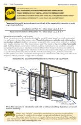
9CABLE CLAMP <strong>INSTALLATION</strong>Install Cable Clamps based ontype of installation needed. CrossBracing Installation consists ofattaching 2" x 6" cross bracingbetween rafter tails. Header MountInstallation consists of attaching toa solid structural member - header,sill plates or wall stud.39°PELLA SUPPORT CABLE SYSTEM(CROSS BRACING MOUNT)PELLA SUPPORT CABLE SYSTEMANCHOR (HEADER MOUNT METHOD)REQUIRES MINIMUM CABLE ANGLE<strong>OF</strong> 39°HEAD SECTIONSILL SECTIONInsulated Seat BoardSupport Bracketsmay be Required."C" Unit Project(1) The Bay/Bow support cables must be attached to structural members capable of supporting 1,300 lbs.Knee braces are required in addition to the support cables if the structural members are not capable ofsupporting 1,300 lbs. Bay/Bow units are not designed to support roof structure.A. Install 2" x 6" cross braces between rafter tails, directlyabove the cable holes in the bay/bow head board.B. Install the cable clamps directly above the ”T“ nuts whereadequate support is available. Holding the clamp parallel tothe up-running cable, drive the #12 x 3-1/4" square screwspart way into the mounting surface using a #3 square drive bit.C. Run the cable up through the bottom of the cable clamp.Hold the cable up tight above the clamp and drive the twocenter clamp screws all the way in, locking the cable in place.Drive the remaining #12 x 3-1/4" square screws all the way.Note: Make sure all four screws are driven in at maximumtorque. Additional tensioning may be done with the nutson the opposite end of the cable at the bottom of the bay/bow unit.D. Installation of knee braces is re<strong>com</strong>mended for all units(and required on units > 8' wide) to help support the weightof the bay/bow unit. Weight calculations must take intoaccount the weight of items that may be placed on the seatboard of the unit. Knee braces are required if more than 500pounds (not including the weight of the bay/bow frame withwindows installed) will need to be supported by the windowseat board.
10 INTERIOR CASING/TRIM <strong>INSTALLATION</strong>Note: Interior casing/trim is sent cut to length. Dry fit all the trim pieces to confirm the correctlength before attaching with 1" brads/finishing nails. If trim pieces are too long they may betrimmed, if they are too short, trim will need to be re-ordered.A. Attach sill trim piece first. (Sill trim piece is notched tofit over the sill pan edge). Attach with finishing nails.B. Attach jamb pieces on both sides of the window.Attach with finishing nails.C. Attach head trim with finishing nails.D. Repeat A-C on all windows in the bay/bow frame.INSTALLING ROTO COVER AND CRANKA. Place the cover over the operator stud andsnap into place.B. Apply pressure to the pocket end of thecover and snap into place.C. Use a medium size flat-blade screwdriver toloosen the set screw in the crank handle.D. Slide the crank handle onto the stud. Unlock,open window, then close and lock window.E. Fold the crank handle down and checkalignment of knob with the pocket.Note: You may need to adjust the crankposition on the stud until the correctalignment is achieved.F. Open the crank and tighten the set screw.G. After the final installation, fold the crank overand snap the knob into the pocket.Note: Even with the window open the crankcan be folded to avoid interfering with thewindow treatments.
LOCK LEVER REMOVAL AND INSERTIONNote: You may want to remove the lock lever if itneeds to be replaced with a different finish.A. Unlock and open the window.B. Place the lock lever in thelocked position.C. From the exterior of the window, look through theopening behind the lock lever to locate the pointwhere the lock lever and lock cam meet.D. Insert an approximately 1/4" wide flat-blade screwdriverstraight into the opening and center the blade tip at thepoint the cam and lever meet.E. Push the screwdriver against the lock cam and rotatethe bottom of the blade toward the lock lever. This willpush the lock cam away from the lock lever hook sothe lever can be removed.F. Remove the lock lever by pulling it straight out towardthe interior of the building.G. To install a lock lever, from the interior hold it in thelocked position and insert into the slot until it snapsonto the cam.Note: The lock cam must be in the locked positionbefore the lock lever can be inserted.
FINISHThe interior and exterior frame and sash are protected by a powder coat baked-on factory finishthat requires no painting. Clean this surface with mild soap and water. Stubborn stains anddeposits may be removed with mineral spirts. DO NOT use abrasives. DO NOT scrape or use toolsthat might damage the surface.Use of inappropriate solvents, brickwash or cleaning chemicals will cause adverse reactions withwindow and door materials and voids the Limited Warranty.CARE AND MAINTENANCECare and maintenance information is available by contacting your local <strong>Pella</strong> retailer. Thisinformation is also available at www.pellaimpervia.<strong>com</strong>.IMPORTANT NOTICEBecause all construction must anticipate some water infiltration, it is important that the wall systembe designed and constructed to properly manage moisture. <strong>Pella</strong> Corporation is not responsiblefor claims or damages caused by anticipated and unanticipated water infiltration; deficiencies inbuilding design, construction and maintenance; failure to install <strong>Pella</strong> ® products in accordancewith <strong>Pella</strong> installation instructions; or the use of <strong>Pella</strong> products in wall systems which do not allowfor proper management of moisture within the wall systems. The determination of the suitability ofall building <strong>com</strong>ponents, including the use of <strong>Pella</strong> products, as well as the design and installationof flashing and sealing systems are the responsibility of the Buyer or User, the architect, contractor,installer, or other construction professional and are not the responsibility of <strong>Pella</strong>.<strong>Pella</strong> products should not be used in barrier wall systems which do not allow for propermanagement of moisture within the wall systems, such as barrier Exterior Insulation and FinishSystems, (EIFS) (also known as synthetic stucco) or other non-water managed systems. Exceptin the states of California, New Mexico, Arizona, Nevada, Utah, and Colorado, <strong>Pella</strong> makes nowarranty of any kind and assumes no responsibility for <strong>Pella</strong> windows and doors installed inbarrier wall systems. In the states listed above, the installation of <strong>Pella</strong> products in barrier wall orsimilar systems must be in accordance with <strong>Pella</strong> installation instructions.Product modifications that are not approved by <strong>Pella</strong> Corporation will void the Limited Warranty.Part Number: 815C0101
This page left blank intentionally.