Overload Safety Couplings - Industrial and Bearing Supplies
Overload Safety Couplings - Industrial and Bearing Supplies
Overload Safety Couplings - Industrial and Bearing Supplies

Create successful ePaper yourself
Turn your PDF publications into a flip-book with our unique Google optimized e-Paper software.
Torq-TenderEnd of Shaft – Type JFTorq-TenderModelsAKMPQRINCH(MM)INCH(MM)INCH(MM)INCH(MM)INCH(MM)INCHTT1XJF TT2JF TT2XJF TT3JF TT3XJF TT4XJF1.562(39.7)1.500(38.1)0.187(4.7)0.875(22.2)1.250(31.7)10-32X 0.25DP2.165(55)1.885(47.9)0.282(7.2)1.200(30.5)1.750(44.4)10-32X 0.37DP2.500(63.5)2.250(57.1)0.325(8.2)1.500(38.1)2.000(50.8)1/4-20X 0.50DP3.000(76.2)2.560(65)0.370(9.4)1.625(41.3)2.375(60.3)5/16-18X 0.56DP3.625(92.1)3.550(90.2)0.400(10.2)2.125(54)3.000(76.2)5/16-18X 0.56DP4.625(117.5)4.375(111.1)0.375(9.5)2.625(66.7)4.000(101.6)3/8-16X 0.75DPAKPMQSee chart on page 8 for bore sizes.C BORER (THREAD SIZE)Torq-TenderEnd of Shaft – Type STorq-TenderModelsTT1X TT2 TT2X TT3DNABDGHIJKLNOINCH(MM)INCH(MM)INCH(MM)INCH(MM)INCH(MM)INCH(MM)INCH(MM)INCH(MM)INCH(MM)INCH(MM)INCH(MN)1.562(39.7)0.875(22.2)1.140(29)1.000(25.4)0.135(3.4)0.205(5.2)1.000(25.4)1.800(45.7)0.600(15.2)0.500(12.7)0.250(6.3)2.165(55)1.250(31.7)1.540(39.1)1.375(34.9)0.250(6.4)0.365(9.3)1.300(33)2.420(61.5)0.750(19)0.625(15.9)0.312(8)2.500(63.5)1.500(38.1)1.805(45.8)1.625(41.3)0.312(8)0.455(11.6)1.500(38.1)2.950(75)1.000(25.4)0.875(22.2)0.375(9.5)3.000(76.2)1.750(44.4)2.100(53.3)1.750(44.4)0.312(8)0.470(11.9)1.812(46)3.470(88.1)1.187(30.1)1.062(27)0.375(9.5)HI J LKA BC BOREGOKTorq-TenderEnd of Shaft – Type JLTorq-TenderModelsTT2TT3AGJKLNOINCH(MM)INCH(MM)INCH(MM)INCH(MM)INCH(MM)INCH(MM)INCH(MM)2.165(55)1.625(41.3)1.950(49.5)2.110(53.6)0.750(19)0.625(15.9)0.312(7.9)3.00(76.2)2.250(57.15)3.060(77.7)3.294(83.7)1.188(30.2)1.03(26.2)0.375(9.5)AJNGOC BORE5
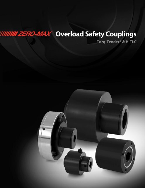
TORQ-TENDER ®OVERLOAD SAFETY COUPLINGSTorq-TenderType CP, BP, <strong>and</strong> SP (with Actuating Pin)Torq-TenderTT1X TT2 TT2X TT3 TT3TAN TT3X TT4XModelsABGKSTUWINCH(MM)INCH(MM)INCH(MM)INCH(MM)INCH(MM)INCH(MM)INCH(MM)INCH(MM)1.562(39.7)0.875(22.2)1.000(25.4)1.800(45.7)0.837(21.5)0.125(3.17)0.180(4.57)0.250(6.35)2.165(55)1.250(31.7)1.375(34.9)2.420(61.5)1.062(27)0.125(3.17)0.125(3.17)0.195(4.95)2.500(63.5)1.500(38.1)1.625(41.3)2.950(75)1.395(35.4)0.125(3.17)0.125(3.17)0.240(6.09)3.000(76.2)1.750(44.4)1.750(44.4)3.470(88.1)1.573(40)0.125(3.17)0.125(3.17)0.175(4.44)Torq-TenderEnd of Shaft Type JP (with Actuating Pin)Torq-TenderModelsAGKNOSTUW3.000(76.2)1.750(44.4)1.750(44.4)4.710(119.6)1.573(40)0.125(3.17)0.125(3.17)0.175(4.44)Torq-TenderEnd of Shaft Type JFP (with Actuating Pin)Torq-TenderModelsAKQRSTUWINCH(MM)INCH(MM)INCH(MM)INCH(MM)INCH(MM)INCH(MM)INCH(MM)INCH(MM)INCH(MM)INCH(MM)INCH(MM)INCH(MM)INCH(MM)INCH(MM)INCH(MM)INCH(MM)INCH(MM)TT22.165(55)1.625(41.3)2.110(53.6)0.625(15.9)0.313(8)1.010(25.7)0.125(3.17)0.125(3.17)0.195(4.95)3.625(92.1)2.250(57.1)2.500(63.5)4.550(115.6)1.791(45.5)0.125(3.17)0.125(3.17)0.175(4.44)4.625(117.5)3.000(76.2)3.000(76.2)5.40(137.2)2.005(50.9)0.125(3.17)0.125(3.17)0.090(2.28)TT1X TT2 TT2X TT3 TT3X TT4X1.562(39.7)1.500(38.1)1.250(31.7)10-32X 0.25DP1.055(26.8)0.125(3.17)0.180(4.57)0.250(6.35)2.165(55)1.885(47.9)1.750(44.4)10-32X 0.37DP1.400(35.6)0.125(3.17)0.125(3.17)0.195(4.95)TT33.000(76.2)2.250(57.1)3.294(83.7)1.040(26.4)0.375(9.5)1.627(41.3)0.125(3.17)0.125(3.17)0.175(4.44)2.500(63.5)2.250(57.1)2.000(50.8)1/4-20X 0.50DP1.608(40.84)0.125(3.17)0.125(3.17)0.240(6.09)3.000(76.2)2.560(65)2.375(60.3)5/16-18X 0.50DP1.912(48.6)0.125(3.17)0.125(3.17)0.175(4.44)3.625(92.1)3.550(90.2)3.000(76.2)5/16-18X 0.56DP2.730(69.3)0.125(3.17)0.125(3.17)0.175(4.44)4.625(117.5)4.375(111.1)4.000(101.6)3/8-16X 0.75DP3.310(84.1)0.125(3.17)0.125(3.17)0.090(2.28)AW U TASW U TBW U TASKKKSGQGRNOTE: TheActuating PinAssembly is asimple pin whichis forced outradially from themain body whenoverload occurs.When using thisoption, it isimportant to notethat the housing(F bore) or externalmounting hub endof the unit is thepower source orinput end. This partof the unit mustcontinue to rotatefor the extendedpin to contact acustomer suppliedlimit switch forshutdown orwarning.®6 www.zero-max.com Phone 800.533.1731 763.546.4300 Fax 763.546.8260
7Torq-TenderType CD, BD, <strong>and</strong> SD (with Actuating Disc)Torq-TenderModelsTT1X TT2 TT2X TT3 TT3TAN TT3X TT4XAINCH(MM)1.562(39.7)2.165(55)2.500(63.5)3.000(76.2)3.000(76.2)3.625(92.1)4.625(117.5)BINCH(MM)0.875(22.2)1.250(31.7)1.500(38.1)1.750(44.4)1.750(44.4)2.250(57.1)3.000(76.2)GINCH(MM)1.000(25.4)1.375(34.9)1.625(41.3)1.750(44.4)1.750(44.4)2.500(63.5)3.000(76.2)KINCH(MM)1.800(45.7)2.420(61.5)2.950(75)3.470(88.1)4.710(119.6)4.550(115.6)5.400(137.2)LINCH(MM)0.600(15.2)0.750(19)1.000(25.4)1.187(30.1)1.187(30.1)1.250(31.7)1.330(33.8)NINCH(MM)0.500(12.7)0.625(15.9)0.875(22.2)1.062(27)1.062(27)1.080(27.4)1.125(28.6)XINCH(MM)2.950(74.9)3.485(88.5)3.935(100)4.460(113.3)4.460(113.3)4.950(125.7)6.16(156.5)YINCH(MM)0.970(24.6)0.970(24.6)0.970(24.6)0.970(24.6)0.970(24.6)0.970(24.6)1.187(30.1)ZINCH(MM)0.080(2)0.570(14.5)0.740(18.8)1.125(28.6)2.345(59.6)1.985(50.4)2.500(63.5)Z1INCH(MM)0.120(3)0.120(3)0.120(3)0.120(3)0.120(3)0.120(3)0.120(3)Torq-TenderEnd of Shaft - Type JFD (with Actuating Disc)Torq-TenderModelsTT1X TT2 TT2X TT3 TT3X TT4XAAINCH(MM)1.530(38.9)2.060(52.3)2.450(62.2)2.895(73.5)3.550(90.2)4.525(114.9)KINCH(MM)1.500(38.1)1.875(47.6)2.250(57.1)2.560(65)3.550(90.2)4.375(111.1)QINCH(MM)1.250(31.7)1.750(44.4)2.000(50.8)2.375(60.3)3.000(76.2)4.000(101.6)RINCH10-32X 0.25DP10-32X 0.37DP1/4-20X 0.50DP5/16-18X 0.50DP5/16-18X 0.56DP3/8-16X 0.75DPXINCH(MM)2.950(74.9)3.485(88.5)3.935(99.9)4.480(113.8)4.950(125.7)6.16(156.5)YINCH(MM)0.970(24.6)0.970(24.6)0.970(24.6)0.970(24.6)0.970(24.6)1.187(30.1)ZINCH(MM)0.187(4.7)0.530(13.5)0.790(20.1)1.150(29.2)1.918(48.7)2.420(61.5)Z1INCH(MM)0.120(3)0.120(3)0.120(3)0.120(3)0.120(3)0.120(3)Torq-TenderEnd of Shaft - Type JD (with Actuating Disc)Torq-TenderModelsTT2TT3AINCH(MM)2.165(55)3.000(76.2)GINCH(MM)1.885(47.9)2.250(57.1)KINCH(MM)2.110(53.6)3.294(83.7)LINCH(MM)0.750(19)1.187(30.1)NINCH(MM)0.625(15.9)1.040(26.4)OINCH(MM)0.313(8)0.375(9.5)XINCH(MM)3.485(88.5)4.480(113.8)YINCH(MM)0.970(24.6)0.970(24.6)ZINCH(MM)0.900(22.9)2.060(52.3)Z1INCH(MM)0.120(3)0.120(3)BAXZYKGLNZ1GAXKLNYZZIQAAXYZZ1KR
TORQ-TENDER ®Determine Torque:Torque is a twisting force thatcauses rotation <strong>and</strong> can betheoretically determined with theuse of this simple formula:Torque (in. lbs.) =63,025 x HPRPMFor example, if your applicationspeed is 100 RPM <strong>and</strong> the HPrating is 1.5, then:T (in. lbs.) =63,025 x 1.5100Your calculated torquerequirement= 945 in. lbs.It is important to note that thereare many factors involved inthe selection of the torquevalue. The calculation aboverepresents a theoretical way todetermine a torque value.Consideration should also begiven to potentially high start uptorques in the drive system. Mostelectric motors have start uptorques that exceed normal runtorque, which makes it necessaryto select a torque as high aspossible without exceeding theprotection limit.(CAUTION: Because of inertia<strong>and</strong>/or energy in powertransfer equipment, torquelimiters will not protect againstpersonal injury)TORQ-TENDER ®HOW TO SELECTTorque ChartModelTorque ValuesInchPoundsModelTT1XTT2TT1X TT2 TT2X TT3 TT3TAN TT3X TT4XNMInchPoundsAPPLICATIONSNMInchPounds NM InchPounds NM InchPoundsNMInchPoundsNMInchPounds3 0.3 4 0.5 18 2.0 18 2.0 240 27.1 300 33.9 750 84.75 0.6 8 0.9 24 2.7 24 2.7 300 33.9 400 45.2 1000 113.08 0.9 12 1.4 28 3.2 36 4.1 360 40.7 500 56.5 1250 141.210 1.1 18 2.0 40 4.5 40 4.5 440 49.7 650 73.4 1500 169.512 1.4 25 2.8 50 5.6 50 5.6 500 56.5 750 84.7 1750 197.715 1.7 30 3.4 60 6.8 60 6.8 600 67.8 850 96.0 2000 226.020 2.3 40 4.5 90 10.2 80 9.0 700 79.1 1000 113.0 2250 254.225 2.8 50 5.6 100 11.3 100 11.3 840 94.9 1150 129.9 2500 282.530 3.4 60 6.8 120 13.6 120 13.6 1000 113.0 1300 146.9 2750 310.740 4.5 85 9.6 135 15.3 150 16.9 1500 169.5 3000 339.050 5.6 100 11.3 150 16.9 180 20.360 6.8 125 14.1 180 20.3 220 24.9Bore Capacity ChartTT2XTT3TT3TANTT3XTT4XMinimumBoreINCH(MM)0.250(8)0.375(10)0.500(12)0.625(14)0.625(14)0.875(22)1.000(25)* See Torque Chart140 15.8 200 22.6 250 28.2Shaft CMaximumBoreINCH(MM)0.500(12)0.625(15)0.750(19)1.00(25)1.00(25)1.375(35)1.750(45)250 28.2 300 33.9300 33.9 350 39.5350 39.5 420 47.5Shaft FMaximumBoreINCH(MM)0.625(15)0.875(20)1.00(25)1.125(28)1.125(28)1.500(40)1.875(48)500 56.5InchPoundsTorque RangeNewtonMeters3 to 60 * 0.3 to 6.8 *4 to 140 * 0.5 to 15.8 *18 to 350 * 2.0 to 39.5 *18 to 500 * 2.0 to 56.5 *240 to 1000 * 27.1 to 113.0 *300 to 1500 * 33.9 to 169.5 *750 to 3000 * 84.7 to 339.0 *ShippingWeightPounds(Kg)1/2(0.23)1 1/4(0.57)2 1/4(1.0)3 1/4(1.47)5(2.27)8(3.63)15(6.8)NM®8 www.zero-max.com Phone 800.533.1731 763.546.4300 Fax 763.546.8260
TORQ-TENDER ®HOW TO ORDERPart Numbering StructureSIZE–CONFIGURATIONF BORE DIAMETERC BORE DIAMETERTORQUE VALUECode Code Type of MountTT1XTT2TT2XTT3TT3TANTT3XTT4XC Shaft to Shaft CouplingCP Shaft to Shaft Couplingwith Actuating PinCD Shaft to Shaft Couplingwith Actuating DiscB Through ShaftBP Through Shaftwith Actuating PinBD Through Shaftwith Actuating DiscJ End of Shaft Type JJP End of Shaft Type Jwith Actuating PinJD End of Shaft Type Jwith Actuating DiscJF End of Shaft Type JFJFP End of Shaft Type JFwith Actuating PinJFD End of Shaft Type JFwith Actuating DiscS End of Shaft MountOutboard loadSP End of Shaft MountOutboard load withActuating PinSD End of Shaft MountOutboard load withActuating DiscSpecify for C, CP, <strong>and</strong>CD otherwise omitSee Bore Capacity ChartAll bores over 0.438" or 10mm willcome with the st<strong>and</strong>ard keywaySpecify for allconfigurationsNote: It is important to correctly identify the different boresfor the Configurations CP <strong>and</strong> CD. These options requirean external device to interface with the Torque Tender suchas a proximity switch. How the bores are specified willaffect the location of the Actuation Pin <strong>and</strong> Actuation Disc.Please contact the factory if further clarification is needed.Example:Size TT3Shaft to Shaft ConfigurationActuating Disc optionF bore is 25mmC bore is 3/4"Torque value is 150 in-lbs.in - lbs.See Chart.Select the inchpound valuefrom the listof valuesavailablefor thespecific sizeModel code is:TT3-CD – 25mm – 3/4" – 150St<strong>and</strong>ard Keyways Inch Bore HubsBore SizeOver ToKeyway0.438 0.562 0.125 x 0.0620.562 0.875 0.187 x 0.0940.875 1.250 0.250 x 0.1251.250 1.375 0.312 x 0.1561.375 1.750 0.375 x 0.187Inch bores are supplied with inch size setscrews.St<strong>and</strong>ard Keyways Metric Bore HubsBore SizeBore SizeKeywayOver To Over ToKeyway10 12 4 x 1.8 58 65 18 x 4.412 17 5 x 2.3 65 75 20 x 4.917 22 6 x 2.8 75 85 22 x 5.422 30 8 x 3.3 85 95 25 x 5.430 38 10 x 3.3 95 110 28 x 6.438 44 12 x 3.3 110 130 32 x 7.444 50 14 x 3.8 130 150 36 x 8.4Metric bores are supplied with metric size setscrews.CUSTOM DESIGNS9
TORQ-TENDER ®H-TLC TORQUE LIMITERSThe Intelligent Alternative to Friction-Type Torque Limiters.The unique features in the Zero-Max H-TLC give the designer wider parameters insolving motion control problems.H-TLC Is Durable. The H-TLC torque limiter is designed for hostileenvironments. In many applications, a torque limiter may wait for months oryears before it is required to disengage. During this time, the torque limitermay be subjected to moisture, corrosion, acids, salts or any number of othercontaminants which inhibit the proper operation of the torque limiter <strong>and</strong>prevent disengagement.The H-TLC will never rust because its major components are designed fromspecial polymer materials that are resistant to water, salts, mild acids <strong>and</strong>most other contaminants. Even in temperatures from -40°F to +180°F (-40°Cto +82°C), the H-TLC still withst<strong>and</strong>s many corrosive elements <strong>and</strong> abuse.H-TLC Is Dependable. It works on a spring loaded convex pin <strong>and</strong> detentdesign which reacts to overloads... but not to lubricants. Unlike friction-typedesigns, you can submerge an H-TLC in oil <strong>and</strong> still depend on precisedisengagement at your design limits.H-TLC Is Repeatable. Unlike friction-type torque limiters the H-TLC does notgenerate an amount of heat which can alter the transmittable torque. When afriction-type torque limiter disengages, it generates heat which often alters itsdisengagement characteristics.The H-TLC’s resilient *Nylatron GS ® <strong>and</strong> **Delrin ® materials will not build up,or retain, the kind of heat unique to friction designs.The Torque Setting Is Adjustable. If operating conditions require periodicchanges in torque settings, the H-TLC gives you that ability. Simply adjust theunit’s external compression bolts until the desired new torque setting is reached.The H-TLC Will Trigger Automatic Alarm <strong>and</strong> Shut-Down Systems.One of the H-TLC’s most important special features is its ingeniously simple <strong>and</strong>inexpensive actuating disc assembly. The optional actuating disc is used toprovide a mechanical displacement that can be sensed <strong>and</strong> feed back into themachines PLC to initiate the proper response.Multi or Single Position Re-Engagement.The H-TLC-500 has 4 re-engagement positions <strong>and</strong> the H-TLC-1000 has 6.If your application must maintain phase, you can order H-TLC with only onere-engagement point. The single position H-TLC torque limiters torque ratingwill vary from the catalog ratings (consult factory for torque range).Model Torque Range Housing Bore Shaft Bore ShippingWeightInchPoundsNewtonMetersMinimumBoreINCH(MM)MaximumBoreINCH(MM)MinimumBoreINCH(MM)MaximumBoreINCH(MM)Pounds(Kg)H-TLC-500 4 to 150 * 0.5 to 16.9 *H-TLC-1000 40 to 500 * 4.5 to 56.5 ** See Torque Chart0.250(8)0.500(13)0.750(18)1.250(30)0.250(8)0.500(13)0.563(15)1.125(28)1/2(0.23)1(0.45)Note: *Nylatron GS ® is a registered trademark of Polymer Corp. **Delrin ® is a registered trademark of EI Dupont Company®10 www.zero-max.com Phone 800.533.1731 763.546.4300 Fax 763.546.8260
H-TLCDimensionsABDEGHH1IJKLMQRXZZ1Models 500 1000INCH(MM)INCH(MM)INCH(MM)INCH(MM)INCH(MM)INCH(MM)INCH(MM)INCH(MM)INCH(MM)INCH(MM)INCH(MM)INCH(MM)INCH(MM)INCHINCH(MM)INCH(MM)INCH(MM)2.00(50.8)1.49(37.8)1.625(41.3)0.855(21.7)1.49(37.8)0.250(6.3)1.250(31.7)0.563(14.3)1.187(30.1)2.50(63.5)0.750(19)0.375(9.5)1.125(28.6)1/4-20x 1/2 DP2.50(63.5)2.275(57.8)2.125(54)3.20(81.3)2.37(60.2)2.230(56.6)1.210(30.7)2.22(56.4)0.315(8)1.625(41.3)0.520(13.2)1.81(58.4)3.45(87.6)1.12(15.9)0.400(10.2)1.687(42.8)5/16-18x 3/4 DP4.040(102.6)3.270(83.1)3.110(79)H-TLC Type CABBAXBC BOREH-TLC Type BN KEYWAYC BOREHHSLEEVE BEARINGH-TLC Type CD <strong>and</strong> BD (with Actuating Disc)IIH1DH1JKJ LKKELMO KEYWAYF BORERGQQSprocket NotIncludedG AZ1ENGAGEDZDISENGAGEDPart Numbering StructureSIZE–CONFIGURATIONF BORE DIAMETERC BORE DIAMETERTORQUE VALUECode Code Type of MountH-TLC-500H-TLC-1000C Shaft to Shaft MountCD Shaft to Shaft Mount with Actuating DiscB Through Shaft MountBD Through Shaft Mount with Actuating DiscExample:Size H-TLCShaft to Shaft ConfigurationActuating Disc optionF bore is 25mmC bore is 3/4"Torque value is 300 to 500 in-lbs.Model code is:H-TLC-1000-CD 25mm 3/4" GoldSpecify for C <strong>and</strong> CDotherwise omitSee Bore Capacity ChartAll bores over 0.438" or 10mm willcome with the st<strong>and</strong>ard keywaySpecify for allconfigurationsNote: It is important to correctly identify the differentbores for the Configuration CD. These options require anexternal device to interface with the H-TLC such as aproximity switch. How the bores are specified will affectthe location of the Actuation Disc. Please contact thefactory if further clarification is needed.Series Code Torque Range500Series1000SeriesBlueRedGoldBlueRedGoldCode4 to 60 In-lbs.0.5 to 6.8 Nm40 to 125 In-lbs.4.5 to 14.1 Nm100 to 150 In-lbs.11.3 to 16.9 Nm40 to 150 In-lbs.4.5 to 16.9 Nm140 to 350 In-lbs.15.8 to 39.5 Nm300 to 500 In-lbs.33.9 to 56.5 Nm11
ServoClass ® <strong>Couplings</strong>Designed for dem<strong>and</strong>ingservomotor applications. Zerobacklash, high torsional stiffnesscoupling. Features flexible metaldiscs <strong>and</strong> keyless clamp-typemounting hubs. <strong>Couplings</strong> areROHS compliant.ETP ® Shaft Locking ConnectionsDesigned for quick, easy <strong>and</strong>accurate assembly of mountedshaft components. Both inch <strong>and</strong>metric bore connections areavailable from stock.CD ® <strong>Couplings</strong>These high performance couplingsout last bellows <strong>and</strong> steel discdesign couplings. The unique designof the composite disc enables theCD <strong>Couplings</strong> ® to withst<strong>and</strong>punishing applications <strong>and</strong> deliverhigh precision performance.Roh’lix ® Linear ActuatorsRoh’Lix ® Linear Actuators convertrotary motion into precise linearmotion. Available in five models.Roh’Lix ® actuators have thrust ratingsfrom 5 to 200 lbs. All modelsfeature built in overload protection.Schmidt Offset <strong>Couplings</strong> ®Schmidt Offset <strong>Couplings</strong> ® aredesigned to h<strong>and</strong>le high amountsof parallel offset up to 17.00”.St<strong>and</strong>ard models with torquecapacities up to 459,000 in-lbs.Adjustable Speed DriveEasy to install <strong>and</strong> maintenance free.Zero-Max Drives offer infinitelyvariable speeds from 0 rpm to 1/4of input rpm. 5 models with torqueranges from 12 in-lbs to 200 in-lbs.Torq-Tender ® <strong>Couplings</strong>Torq-Tender ® <strong>Couplings</strong> providereliable overload protection in anymechanical power transmissionsystem. Torque ranges from 2 to3000 in-lbs.Crown Gear DrivesCrown Gear Drives ® are available with1:1 <strong>and</strong> 2:1 ratios. High quality AGMAclass 10 spiral bevel gears. Stainlesssteel shafts <strong>and</strong> aluminum housings arest<strong>and</strong>ard on all Crown Gear Drives ® .Control-Flex ® <strong>Couplings</strong>Control-Flex ® <strong>Couplings</strong> are zerobacklash couplings designed forencoder <strong>and</strong> instrumentationtype applications.OHLA ® Overhung Load AdaptersOHLA ® Overhung Load Adapters aredesigned to eliminate radial <strong>and</strong> axialloads from a hydraulic pump or motor.11 models available for mounts fromSAE A to SAE F.Warranty. Zero-Max, Inc. the manufacturer, warrants that for a period of 12 months from date of shipment it will repair, or at its option, replace any new apparatus which proves defective in material or workmanship, orwhich does not conform to applicable drawings <strong>and</strong> specifications approved by the manufacturer. All repairs <strong>and</strong> replacements shall be F.O.B. factory. All claims must be made in writing to the manufacturer. • In no event<strong>and</strong> under no circumstances shall manufacturer be liable for (a) damages in shipment; (b) failures or damages due to misuse, abuse, improper installation or abnormal conditions of temperature, dirt, water or corrosives; (c)failures due to operation, intentional or otherwise, above rated capacities, <strong>and</strong> (d) non-authorized expenses for removal, inspection, transportation, repair or rework. Nor shall manufacturer ever be liable for consequential<strong>and</strong> incidental damages, or in any amount greater than the purchase price of the apparatus. • Zero Max, Inc. reserves the right to discontinue models or to change specifications at any time without notice. No discontinuanceor change shall create any liability on the part of Zero-Max, Inc. in respect to its products in the h<strong>and</strong>s of customers or products on order not incorporating such changes even though delivered after any such change. • Thiswarranty is in LIEU OF ALL OTHER WARRANTIES, EXPRESS OR IMPLIED, INCLUDING (BUT NOT LIMITED TO) ANY IMPLIED WARRANTIES OF MERCHANTABILITY OR FITNESS FOR A PARTICULAR PURPOSE. THE TERMS OF THISWARRANTY CONSTITUTE ALL BUYER’S OR USER’S SOLE AND EXCLUSIVE REMEDY, AND ARE IN LIEU OF ANY RIGHT TO RECOVER FOR NEGLIGENCE, BREACH OF WARRANTY, STRICT TORT LIABILITY OR UPON ANY OTHER THEORY.Any legal proceedings arising out of the sale or use of this apparatus must be commenced within 18 months of the date of purchase. • CAUTION: Rotating equipment must be guarded. Also refer to OSHA specifications <strong>and</strong>recommendations. • Zero-Max® , CD ® , ETP ® , ServoClass ® , Torq-Tender ® , Control-Flex ® , Posi-Lok ® <strong>and</strong> Roh'Lix ® are registered trademarks of Zero-Max, Inc. In U.S.A. OHLA is a trademark of Zero-Max, Inc.© Zero-Max 2011 Printed in U.S.A.13200 Sixth Avenue North,Plymouth, Minnesota 55441-5509Phone: 800-533-1731 (763) 546-4300Fax (763) 546-8260 www.zero-max.com