Cast-resin transformers excel in their fire behavior - Siemens Power ...
Cast-resin transformers excel in their fire behavior - Siemens Power ...
Cast-resin transformers excel in their fire behavior - Siemens Power ...

You also want an ePaper? Increase the reach of your titles
YUMPU automatically turns print PDFs into web optimized ePapers that Google loves.
Technical Paper ■ Author: Fritz Sorg, Rudolf Hanov, He<strong>in</strong>z Raithel<strong>Cast</strong>-<strong>res<strong>in</strong></strong> <strong>transformers</strong><strong>excel</strong> <strong>in</strong> <strong>their</strong> <strong>fire</strong> <strong>behavior</strong><strong>Power</strong> Transmission and Distribution
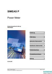
Wherever distribution <strong>transformers</strong> are used<strong>in</strong> locations very close to people, GEAFOL cast<strong>res<strong>in</strong></strong><strong>transformers</strong> are the low-risk answer.<strong>Cast</strong>-<strong>res<strong>in</strong></strong> <strong>transformers</strong> lack the limitations ofoil-<strong>in</strong>sulated <strong>transformers</strong> but share <strong>their</strong> desirableproperties, such as operational reliabilityand a long service life. Today more than 80,000GEAFOL cast-<strong>res<strong>in</strong></strong> <strong>transformers</strong> have alreadyproven themselves <strong>in</strong> supply<strong>in</strong>g electric powerto subway tunnels, coal m<strong>in</strong>es, airports, w<strong>in</strong>dpower systems and even on cruise ships and <strong>in</strong>nuclear power plants. In many cases, the keyfactor prompt<strong>in</strong>g decision-makers to choose thecast-<strong>res<strong>in</strong></strong> version was its superior <strong>fire</strong> <strong>behavior</strong>.The results of <strong>fire</strong> <strong>behavior</strong> tests at well-knowntest laboratories prove that GEAFOL cast-<strong>res<strong>in</strong></strong><strong>transformers</strong> – especially <strong>in</strong> comparison to oil<strong>in</strong>sulated<strong>transformers</strong> – are the best choicewhen it comes to <strong>fire</strong> <strong>behavior</strong>.<strong>Cast</strong>-<strong>res<strong>in</strong></strong> <strong>transformers</strong><strong>excel</strong> <strong>in</strong> <strong>their</strong> <strong>fire</strong> <strong>behavior</strong>Fritz Sorg, Rudolf Hanov, He<strong>in</strong>z Raithel*The GEAFOL cast-<strong>res<strong>in</strong></strong> <strong>transformers</strong> which <strong>Siemens</strong><strong>Power</strong> Transmission and Distribution (PTD) producesat its transformer plants are <strong>fire</strong>-retardant and selfext<strong>in</strong>guish<strong>in</strong>g(Figure 1).If they are <strong>in</strong>volved by an external <strong>fire</strong>, they do notsignificantly affect the course of the <strong>fire</strong> thanks to<strong>their</strong> low <strong>fire</strong> load. Nor do the coils of the GEAFOLcast-<strong>res<strong>in</strong></strong> transformer ignite from short-circuit arcscaused by <strong>in</strong>ternal defects. Moreover, no toxic componentsare produced, other than the type of flue gasescommon to <strong>fire</strong>s. <strong>Siemens</strong> advises its customers forsafety reasons, especially with respect to <strong>fire</strong> <strong>behavior</strong>,to use GEAFOL cast-<strong>res<strong>in</strong></strong> <strong>transformers</strong> <strong>in</strong> <strong>in</strong>frastructuralprojects such as department stores or officebuild<strong>in</strong>gs. What’s more, the operator benefits fromother advantages, such as superior economy and<strong>excel</strong>lent environmental compatibility.Dry-type <strong>transformers</strong> must always be specifiedaccord<strong>in</strong>g to <strong>their</strong> tested and proven Environmental,Climatic and Fire Category. GEAFOL cast-<strong>res<strong>in</strong></strong> <strong>transformers</strong>comply with Environmental Category E2,Climate Category C2 and Fire Category F1 – thehighest categories def<strong>in</strong>ed <strong>in</strong> IEC 60076-11, whichmeans that they deliver the highest level of operationalsafety.Figure 1: GEAFOL cast-<strong>res<strong>in</strong></strong> transformer <strong>in</strong> the test bay at the<strong>Siemens</strong> transformer plant <strong>in</strong> Kirchheim/Teck: If GEAFOL cast<strong>res<strong>in</strong></strong><strong>transformers</strong> are <strong>in</strong>volved by an external <strong>fire</strong>, they don’tsignificantly affect the course of the <strong>fire</strong> thanks to <strong>their</strong> low<strong>fire</strong> load. Nor do <strong>their</strong> coils ignite from short-circuit arcscaused by <strong>in</strong>tr<strong>in</strong>sic flaws. Moreover, no toxic components areproduced, other than the type of flue gases common to <strong>fire</strong>s.100%8863OilSiliconeoilAskarel17GJ1510.5Heat of combustionIf one compares the energy content liberated dur<strong>in</strong>gcomplete combustion of all <strong>in</strong>sulat<strong>in</strong>g materials <strong>in</strong><strong>transformers</strong> filled with m<strong>in</strong>eral oil, silicone oil, orester liquid with that of cast-<strong>res<strong>in</strong></strong> <strong>in</strong>sulated distribution<strong>transformers</strong>, the comparison <strong>in</strong>variably favorsthe cast-<strong>res<strong>in</strong></strong> transformer. For example, the combustionenergy of a 630-kVA m<strong>in</strong>eral oil transformer ismore than four times that of a GEAFOL cast-<strong>res<strong>in</strong></strong>transformer (Figure 2).This comparison does not <strong>in</strong>clude characteristicssuch as flammability and combustion speed, butis shows that the <strong>fire</strong> load of cast-<strong>res<strong>in</strong></strong> <strong>in</strong>sulated<strong>transformers</strong> is substantially lower than that ofliquid-filled <strong>transformers</strong>.24GEAFOL4.000Figure 2: Combustion heat of the <strong>in</strong>sulat<strong>in</strong>g materials ofcomparable 630-kVA <strong>transformers</strong> with different <strong>in</strong>sulat<strong>in</strong>gmaterials: The combustion energy of a 630-kVA m<strong>in</strong>eral oiltransformer amounts to more than four times that of aGEAFOL cast-<strong>res<strong>in</strong></strong> transformer.* Fritz Sorg, Dipl.-Ing., Manager of Research & Development,Rudolf Hanov, Dipl.-Ing., Project Manager of Research &Development and He<strong>in</strong>z Raithel, Dipl.-Ing., Director Sales &Market<strong>in</strong>g of the Transformer Plant Kirchheim/Teck of the<strong>Siemens</strong> Group <strong>Power</strong> Transmission and Distribution (PTD).2
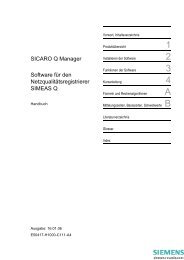
The design of the w<strong>in</strong>d<strong>in</strong>gs and the cast<strong>res<strong>in</strong></strong>mixture determ<strong>in</strong>e the <strong>fire</strong> <strong>behavior</strong>The <strong>fire</strong> <strong>behavior</strong> of the cast-<strong>res<strong>in</strong></strong> <strong>transformers</strong> which<strong>Siemens</strong> manufactures, for example, <strong>in</strong> Kirchheim,Germany is dictated chiefly by the w<strong>in</strong>d<strong>in</strong>g arrangementbecause this has a crucial <strong>in</strong>fluence on theproperties of the cast <strong>res<strong>in</strong></strong> mixes that can be used.One of the secrets of good or bad <strong>fire</strong> <strong>behavior</strong> of acast-<strong>res<strong>in</strong></strong> transformer is related to the mix<strong>in</strong>g ratioof the <strong>in</strong>sulation, which consists of an environmentallycompatible and recyclable epoxy <strong>res<strong>in</strong></strong>/quartzpowder mixture <strong>in</strong> the GEAFOL transformer. TheKirchheim plant produces the <strong>in</strong>sulat<strong>in</strong>g material forits cast-<strong>res<strong>in</strong></strong> <strong>transformers</strong> from a mixture of two-thirdsquartz powder and one-third epoxy <strong>res<strong>in</strong></strong> to create<strong>transformers</strong> that are on the safe side with respectto <strong>their</strong> subsequent <strong>fire</strong> <strong>behavior</strong>.This is confirmed by prestigious test<strong>in</strong>g laboratorieswhere <strong>Siemens</strong> has its cast-<strong>res<strong>in</strong></strong> <strong>transformers</strong> testedfor <strong>fire</strong> safety. As a case <strong>in</strong> po<strong>in</strong>t, <strong>in</strong> 2005 a 1500-kVAtransformer was extensively and successfully tested<strong>in</strong> the test<strong>in</strong>g laboratory of CESI (Centro ElettrotecnicoSperimentale Italiano) <strong>in</strong> Italy – <strong>in</strong>clud<strong>in</strong>g teststo validate Fire Category F1 accord<strong>in</strong>g to IEC 600076– 11 Section 28.3 (Figure 3).In this test, a replica of a transformer leg wassimultaneously exposed to:■ Flames from a trough filled with burn<strong>in</strong>g spirits■ Radiant heat from a vertical radiant heater wall(24 kW, 750 °C)The follow<strong>in</strong>g test criteria were used:■ The maximum temperature of emitted gases andits variation over time■ The generation of smoke development (the meanvalue of the degree of light transmission from the20th to the 60th m<strong>in</strong>ute after the start of the testmust not be less than 20 %).The good results of the <strong>fire</strong> <strong>behavior</strong> tests wereachieved without the addition of flame-retardantmaterials such as halogens. Nor had any additivessuch as alum<strong>in</strong>a trihydrate been used that impairmechanical strength.These tests had been preceded by earlier <strong>fire</strong> <strong>behavior</strong>tests for flue gases <strong>in</strong> the Allianz Technology Centerand by tests of the pyrolysis products of moldedcast-<strong>res<strong>in</strong></strong> material used <strong>in</strong> GEAFOL <strong>transformers</strong>.The test results demonstrated that the <strong>transformers</strong>could not self-ignite due to short-circuit arcs associatedwith <strong>in</strong>tr<strong>in</strong>sic flaws. If they become <strong>in</strong>volved <strong>in</strong>an external <strong>fire</strong>, they do not significantly <strong>in</strong>tensifythe course of the <strong>fire</strong> thanks to <strong>their</strong> low <strong>fire</strong> load.The tests also demonstrated that any impairmentsor hazards due to heat and gases from the <strong>fire</strong> arelargely the same as <strong>in</strong> ord<strong>in</strong>ary <strong>fire</strong>s.These tests were designed to study the <strong>behavior</strong> ofGEAFOL cast-<strong>res<strong>in</strong></strong> <strong>transformers</strong> <strong>in</strong> critical operat<strong>in</strong>gconditions, for <strong>in</strong>stance under the <strong>in</strong>fluence ofhighly energetic short-circuit arcs, or when thetransformer becomes <strong>in</strong>volved <strong>in</strong> external <strong>fire</strong>s. Particularemphasis was placed on test<strong>in</strong>g for environmentalimpact as well as for potential toxicity of thegases from the <strong>fire</strong>. Another priority was protectionof bodies of water. A cast-<strong>res<strong>in</strong></strong> <strong>in</strong>sulated, dry-typetransformer is fully compliant with the relevant standards,such as those of VDE 0101 concern<strong>in</strong>g <strong>fire</strong>protection and protection of bodies of water. Sucha transformer is therefore the product of choice forapplications <strong>in</strong> which meet<strong>in</strong>g these conditions isparamount.The consequences of <strong>fire</strong> impact also had to be researchedcarefully and expertly <strong>in</strong> order to rule outabsolutely any hazards such as those associated withPCB-filled <strong>transformers</strong> (PCB = polychlor<strong>in</strong>atedbiphenyls 1) ). The ma<strong>in</strong> criterion was the question ofwhether and under what conditions a cast-<strong>res<strong>in</strong></strong>transformer can burn and what combustion productscan occur. Combustion is an autonomous processonce the source of ignition or <strong>fire</strong> has been removed,<strong>in</strong> other words, the process is determ<strong>in</strong>ed by theenergetic balance of the reaction heat and the heatdissipation. Heat <strong>in</strong>put from the flame causes theplastic to be heated and decomposed. The gaseousdecomposition products burn. It is the very natureof autothermal processes that without sufficientheat <strong>in</strong>put from the combustion itself no susta<strong>in</strong>ablecombustion is possible. If cast-<strong>res<strong>in</strong></strong> molded materialsand w<strong>in</strong>d<strong>in</strong>gs embedded there<strong>in</strong>, or synthetic liquidsand plastic <strong>in</strong>sulat<strong>in</strong>g materials, are exposed to flames,the heat <strong>in</strong>put can cause the temperature to reachthe ignition level. In the presence of sufficient oxygen<strong>in</strong>put, gaseous products then ignite.Two conditions must therefore be met <strong>in</strong> orderto ma<strong>in</strong>ta<strong>in</strong> a stable, self-susta<strong>in</strong><strong>in</strong>g combustion:First, the temperature of the material must riseto the ignition po<strong>in</strong>t, which is above 450 °C <strong>in</strong> theGEAFOL cast-<strong>res<strong>in</strong></strong> molded material. Second, thecombustion must generate a sufficient quantityof heat to susta<strong>in</strong> itself.Figure 3 a + b: Very goodresistance to direct flameaction was certified:1,500-kVA GEAFOL cast<strong>res<strong>in</strong></strong>transformer under testat the CESI Test Institute <strong>in</strong>July 2005 before (above)and after (below) test<strong>in</strong>gto verify compliance withIEC 600076 <strong>fire</strong> category F1.1) Note: Production of PCB-filled <strong>transformers</strong> is banned today but there are still some <strong>in</strong> operation subject to strict regulations.3
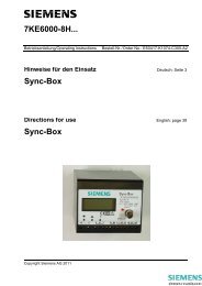
Realistic tests of the <strong>fire</strong> <strong>behavior</strong>of cast-<strong>res<strong>in</strong></strong> <strong>transformers</strong>[a][b]The experimental tests of the <strong>fire</strong> <strong>behavior</strong> of cast<strong>res<strong>in</strong></strong>dry-type <strong>transformers</strong> were conducted underrealistic conditions on complete <strong>transformers</strong> <strong>in</strong> twodirections:■ The effect of high-power arcs on the <strong>in</strong>terior andon the surface of the transformer■ The effect of adjacent <strong>fire</strong>s on the transformerand an analysis of the gases from the <strong>fire</strong>Standard versions of 800-kVA <strong>transformers</strong> wereselected for these tests.The low <strong>fire</strong> load of GEAFOL cast-<strong>res<strong>in</strong></strong> <strong>transformers</strong>stems from the fact that over 90 percent of <strong>their</strong>weight is contributed by metallic materials such aselectric sheet, alum<strong>in</strong>um and steel, and less than tenpercent by <strong>in</strong>sulat<strong>in</strong>g materials. Moreover, only abouthalf of the mass of the <strong>in</strong>sulat<strong>in</strong>g materials is combustible,while two-thirds of the cast-<strong>res<strong>in</strong></strong> <strong>in</strong>sulationconsists of silicon dioxide (SiO 2 ) – <strong>in</strong> other words, ofvery f<strong>in</strong>e quarz sand. The bottom l<strong>in</strong>e: Less than fivepercent of the total weight of a GEAFOL cast-<strong>res<strong>in</strong></strong>transformer is contributed by combustible materials.Figure 4: GEAFOL cast-<strong>res<strong>in</strong></strong> transformer<strong>in</strong> the short circuit arc test:a) Before the testb) Dur<strong>in</strong>g the testc) After the test[c]Fire <strong>behavior</strong> tests<strong>in</strong> the presence of arcsInternal transformer defects <strong>in</strong> cast-<strong>res<strong>in</strong></strong> <strong>transformers</strong>– such as shorts between turns, coil shorts, rarelyflashovers (phase-phase or phase-ground) or disruptivedischarges from the higher-voltage w<strong>in</strong>d<strong>in</strong>g tothe lower-voltage w<strong>in</strong>d<strong>in</strong>g – can cause short-circuitarcs with temperatures of up to 10,000 °C that affectthe <strong>in</strong>sulat<strong>in</strong>g materials. The duration of such arcs islimited by fusegear that is located upstream to thetransformer and typically has a break time of lessthan 0.3 seconds.To evaluate the <strong>behavior</strong> of the cast-<strong>res<strong>in</strong></strong> transformer<strong>in</strong> the presence of arcs, arc tests were conducted onan 800-kVA GEAFOL transformer at the high-powertest station of Forschungsgeme<strong>in</strong>schaft für Hochspannungs-und Hochstromtechnik e.V., a test<strong>in</strong>glaboratory <strong>in</strong> Mannheim, Germany. The test conditionswere more demand<strong>in</strong>g than conditions encountered<strong>in</strong> actual practice. Tests 1 and 2 posed thefollow<strong>in</strong>g conditions:■ Three-phase HV term<strong>in</strong>al short circuit,triggered by an igniter wire■ Short circuits of 0.5 second and2 seconds duration■ Transformers at operat<strong>in</strong>g temperature (w<strong>in</strong>d<strong>in</strong>gs<strong>in</strong> the short circuit heated to nearly 100 °C)■ Short circuit power 150 MVA.Figure 4 shows the transformer with the igniter wirepoised directly beneath the delta connect<strong>in</strong>g block,as well as the arc dur<strong>in</strong>g the short circuit and thetransformer after the two-second short circuit.Exposed to the heat of the short-circuit arc, some ofthe <strong>res<strong>in</strong></strong> components of the cast-<strong>res<strong>in</strong></strong> molded materialwere consumed by <strong>fire</strong> <strong>in</strong> a th<strong>in</strong> surface layer.What rema<strong>in</strong>ed <strong>in</strong> place there was a quartz powder4
LV w<strong>in</strong>d<strong>in</strong>gwith axialduct[a]structure and traces of carbon black, with the quartzpowder layers created by the <strong>fire</strong> provid<strong>in</strong>g a protectiveeffect for the deeper <strong>res<strong>in</strong></strong> layers. At the basepo<strong>in</strong>ts of the arc on the metallic term<strong>in</strong>als, the conductormaterial partially melted and vaporized. Oncethe arc collapsed, no residual burn<strong>in</strong>g of <strong>in</strong>sulat<strong>in</strong>gmaterials was visible. This was also confirmed by filmsmade with high-speed cameras. Despite the visiblesurface damage, the transformer rema<strong>in</strong>ed functional.HV6451327231456Follow<strong>in</strong>g the two arc test, the transformer was subjectedto two additional tests: Holes were drilled <strong>in</strong>tothe HV w<strong>in</strong>d<strong>in</strong>gs of all three phases, then six-millimeter-thicknails were <strong>in</strong>serted and connected toigniter wire, with the object of creat<strong>in</strong>g direct shortcircuits at <strong>in</strong>dividual turns and w<strong>in</strong>d<strong>in</strong>gs. The resultwas the same: Although on phase U a portion of aHV coil was actually blown off by the extremely highforces of the short circuit, no ignition or subsequentburn<strong>in</strong>g of the cast-<strong>res<strong>in</strong></strong> molded material or other<strong>in</strong>sulation portions was <strong>in</strong>duced, even by these rigorousmeasures.Fire <strong>behavior</strong> tests with woodand propane fueled <strong>fire</strong>As early as <strong>in</strong> 1983, <strong>fire</strong> <strong>behavior</strong> tests had beenconducted with an 800-kVA GEAFOL cast-<strong>res<strong>in</strong></strong> transformer<strong>in</strong> the <strong>fire</strong> test build<strong>in</strong>g at the Allianz Centerof Technology <strong>in</strong> Isman<strong>in</strong>g, near Munich. To studythe <strong>fire</strong> <strong>behavior</strong>, the test objects were exposed totwo types of <strong>fire</strong>: external <strong>fire</strong>s fueled by wood andexternal <strong>fire</strong>s fueled by propane gas. These directexposures to different external <strong>fire</strong>s were designedto emulate the exposure of <strong>transformers</strong> to differentpatterns of flames. The wood-fueled <strong>fire</strong> – set up onthe floor of the <strong>fire</strong> test build<strong>in</strong>g – exposed the testtransformer on a relatively broad front, but its impacton the <strong>in</strong>sulat<strong>in</strong>g materials of the w<strong>in</strong>d<strong>in</strong>gs was partiallyimpeded by local shield<strong>in</strong>g provided by the ironcore and portions of the frame. On the other hand,the flames of the propane gas burner exposed thelower area of the w<strong>in</strong>d<strong>in</strong>gs directly and unimpeded.The second test setup exposed the transformer tothe most severe test. Though the overall extent andscope of the <strong>fire</strong> was greater with the wood <strong>fire</strong> than<strong>in</strong> the propane <strong>fire</strong>, the <strong>fire</strong> damage was clearlygreater with the propane gas. The transformer wasfitted at the core, LV- and HV-w<strong>in</strong>d<strong>in</strong>gs with a totalof 16 high-temperature resistant nickel chrome-nickelthermocouples, <strong>in</strong> a symmetrical arrangement ofeight thermocouples each for both tests. The <strong>fire</strong>woodused for the external wood <strong>fire</strong> consisted of ten kilogramsof untreated fir wood, stacked bon<strong>fire</strong>-fashiondirectly under the W transformer leg and ignitedwith the aid of <strong>excel</strong>sior. The calorific value of theapplied amount of fir wood amounted to about188 MJ and temperature of the flames ranged upto 1000 °C.In the setup with the propane gas <strong>fire</strong>, eight propanegas burners with a broad flame pattern were arrangedequidistantly around the base so as to evenly flamethe underside of the HV w<strong>in</strong>d<strong>in</strong>g of the U leg. The560°C480400320240160800720°C640560480400320240160▲Limb UGas external <strong>fire</strong>Exposure to flameExposure to flameLimb V[b]Figure 5: Temperature-time relation at the test transformer dur<strong>in</strong>g the course of the <strong>fire</strong>:a) Location of the thermocouples at the transformerb) Test 1 with external wood <strong>fire</strong>c) Test 2 with external propane gas <strong>fire</strong>distance of the burner from the lower edge of thecoil was about 60 millimeters, the flame orientationabout 45°, and the flame temperature ranged up to1200 °C. The external flame was ma<strong>in</strong>ta<strong>in</strong>ed for30 m<strong>in</strong>utes. The measured gas consumption dur<strong>in</strong>gthat time amounted 2,400 grams. At a specificcalorific value of 46,340 kJ/kg this corresponds toa total calorific value of about 111 MJ. The variationof the temperature over time at the w<strong>in</strong>d<strong>in</strong>gs of thetransformer reflects the course of the <strong>fire</strong> with thewood setup and the propane gas setup, respectively(Figure 5).▲Limb WWood external <strong>fire</strong>54 Measur<strong>in</strong>g13 po<strong>in</strong>ts6 Limb W2787 Room temperature, ceil<strong>in</strong>g – 8 Room temperature, wall[c]Flame ext<strong>in</strong>guishesafter approx.50 m<strong>in</strong>.807 Limb V8 Roomtemperature,0ceil<strong>in</strong>g0 5 10 15 20 25 30 35 40 45 50 m<strong>in</strong> 60t541362Measur<strong>in</strong>gpo<strong>in</strong>tsLimb U5
[a]Under the prolonged effect of the high temperaturesof the external <strong>fire</strong>, the <strong>in</strong>sulat<strong>in</strong>g materials of theLV and HV w<strong>in</strong>d<strong>in</strong>gs ignited, and due to the drafteffect of the axial channel <strong>in</strong> the LV w<strong>in</strong>d<strong>in</strong>g andof the leakage channel, more <strong>in</strong>tense combustionwith a visible flame occurred above the transformer(Figure 6). Noteworthy was the fact that the outersurface of the HV w<strong>in</strong>d<strong>in</strong>g was set a<strong>fire</strong> only <strong>in</strong> theimmediate area of the external <strong>fire</strong>, and that the <strong>fire</strong>spread only m<strong>in</strong>imally to the adjacent transformer leg.[b][c][d][e]Figure 6: Combustion sequence dur<strong>in</strong>g exposureto flames of the external wood <strong>fire</strong>:The outer surface of the HV w<strong>in</strong>d<strong>in</strong>g was ignitedonly <strong>in</strong> the immediate area of exposure to theexternal <strong>fire</strong>, and hardly any <strong>fire</strong> spread to theadjacent leg.[f]6
Figure 7 shows the <strong>fire</strong> <strong>behavior</strong> of the transformer<strong>in</strong> a temporal sequence dur<strong>in</strong>g the test with the externalpropane gas <strong>fire</strong>. The <strong>fire</strong> and the visible flamewere more <strong>in</strong>tense than <strong>in</strong> the wood <strong>fire</strong>. Nevertheless,the flame action dim<strong>in</strong>ished immediatelyafter the propane gas burner was shut off, and selfext<strong>in</strong>guishedcompletely <strong>in</strong> about 20 m<strong>in</strong>utes.Burn<strong>in</strong>g portions of the <strong>in</strong>sulation self-ext<strong>in</strong>guishedafter removal of the external energy <strong>in</strong>put. The hardpapercomponent of the support blocks cont<strong>in</strong>uedto burn with small flames. Surfaces exposed directlyto the flames were severely affected, while adjacentportions of the <strong>in</strong>sulat<strong>in</strong>g material rema<strong>in</strong>ed largelyundamaged. Even <strong>in</strong> the leakage channel, the <strong>fire</strong>did not spread horizontally – despite the extremelyabundant <strong>in</strong>put of oxygen (Figure 9).In Figure 9 is it is clearly evident that the alum<strong>in</strong>umof the LV w<strong>in</strong>d<strong>in</strong>g of the U leg has been heated to alevel exceed<strong>in</strong>g the melt<strong>in</strong>g temperature. In addition,the overall view of the HV w<strong>in</strong>d<strong>in</strong>gs shows that the<strong>fire</strong>s at the outer legs did not spread to the centerleg <strong>in</strong> substantial degree (Figure 8).Figure 8: Condition of the test object after the <strong>fire</strong><strong>behavior</strong> test: The overall view of the HV w<strong>in</strong>d<strong>in</strong>gsalso shows that the <strong>fire</strong>s at the outer legs did notspread to the center leg <strong>in</strong> substantial degree.[a][b]Figure 9: LV w<strong>in</strong>d<strong>in</strong>gs after the <strong>fire</strong> <strong>behavior</strong> test:Surfaces exposed directly to the flames wereseverely affected, while adjacent portions of the<strong>in</strong>sulat<strong>in</strong>g material rema<strong>in</strong>ed largely undamaged.Even <strong>in</strong> the leakage channel the <strong>fire</strong> was did notspread horizontally – despite the extremelyabundant <strong>in</strong>put of oxygen.[c][d]Figure 7:Combustion sequence dur<strong>in</strong>g exposure by the external propane gas <strong>fire</strong>.a) After six m<strong>in</strong>utes b) After eight m<strong>in</strong>utesc) After 20 m<strong>in</strong>utes d) After 33 m<strong>in</strong>utes7
Flue gas:sample collection and analysis resultsThe <strong>fire</strong> room where the tests were conducted hasa floor space of four by four meters and a height of4.1 meters. It was ventilated by fresh air blownthrough one <strong>fire</strong>wall, with the flue gas exhaustedthrough opposite <strong>fire</strong>wall. This is where the 3-cmthickpipe for the collection of the flue gas sampleswas located. The pipe ran up vertically the entireheight of that wall and was equipped at 50-cm <strong>in</strong>tervalswith apertures about 10 square centimeters <strong>in</strong>size to admit the flue gas. Located <strong>in</strong> these apertureswere storage filters. The flue gases were extracted bya membrane pump, and pumped at a rate of 30 litersper m<strong>in</strong>ute directly to the gas chromatography massspectrometer. The l<strong>in</strong>e was about 25 meters long.Dur<strong>in</strong>g the measurement, the l<strong>in</strong>e and the membranepump were heated to 200 °C. Ten microlitersof flue gas were collected at 20-second <strong>in</strong>tervalsthrough a split system and a gas meter<strong>in</strong>g device foronl<strong>in</strong>e measurement. A capillary gas chromatograph<strong>in</strong>stalled here was used only as an <strong>in</strong>terface for themass spectrometer, not for the prelim<strong>in</strong>ary separationof the combustion gases. At approximatelyone-second <strong>in</strong>tervals, mass spectra <strong>in</strong> the rangefrom m/e = 12 to m/e = 650 were obta<strong>in</strong>ed andstored (m/e: mass-charge ratio).Concurrently with the onl<strong>in</strong>e registration of the massspectra, gas samples were withdrawn for the quantitativeanalysis of the flue gas components (gas collect<strong>in</strong>gtubes). Table 1 summarizes the mass-spectrometricresults of the combustion gas analyses andshows the qualitative composition of the combustiongases from the onl<strong>in</strong>e analysis as a relative functionof the maximum peak CO 2 <strong>in</strong>tensity = 100 %.m/e Molecular or fragment ion Isotope ratio Maximal peak <strong>in</strong>tensity 2 ) %Wood <strong>fire</strong>Gas <strong>fire</strong>22 CO2+2 Carbon dioxide, double charged 0.27 0.3425 C 2 H + Fragment ion of azetylene 0.025 0.0326 C 2 H+2 Azetylene 0.18 0.1744 CO+2 Carbon dioxide12C 10016O 100 100 1004513CO+2 Carbon dioxide isotope13C 1.12 1.81 2.17C 2 H 5 O +Fragment of Ethanol4612C 16 O 18 O Carbon dioxide isotope18O 0.204 0.65 0.75C 2 H 6 O +Ethanol50 C 4 H+2 Aromatic fragment 0.02 0.0278 C 6 H+6 Benzene 0.06 0.0691 C 7 H+7 Toluene fragment 0.05 0.0492 1) C 7 H+8 Toluene 0.03 0.02Table 1: Mass spectroscopy of the combustion products of a cast-<strong>res<strong>in</strong></strong> transformer1) For m/e larger than 92, no data that meet the specified premises2) CO 2 peak set = 100 %8
The course of the <strong>fire</strong> can be tracked by the <strong>in</strong>tensityof the molecular ions of carbon dioxide CO 2+(masschargeratio m/e = 44; Figures 10 and 11). Carbondioxide is therefore used as the target gas for theevaluation of the course of the <strong>fire</strong>.0.30%0.1500.10%0.0500.20%0.100100%500CO 22+m/e = 22C 2 H +m/e = 25C 2 H 2+•m/e = 26CO 2+•m/e = 440.30%0.1500.10%0.0500.20%0.100100%500CO 22+m/e = 22C 2 H +m/e = 25C 2 H 2+•m/e = 26CO 2+•m/e = 441.80%0.9000.6%0.3013CO 2+•+C 2 H 5 O +m/e = 45[C 18 O 16 O] + •C 2 H 5 OH +•m/e = 461.80%0.9000.6%0.3013CO 2+•+C 2 H 5 O +m/e = 45[C 18 O 16 O] + •C 2 H 5 OH +•m/e = 460.10%0.0537CI + m/e = 370.10%0.0537CI + m/e = 37000.10%0.05C 4 H 2+m/e = 500.10%0.05C 4 H 2+m/e = 50000.10%0.05C 6 H 6+•m/e = 780.10%0.05C 6 H 6+•m/e = 7800Peak <strong>in</strong>tensity0.10%0.0500.10%0.050C 7 H 7+m/e = 91C 7 H 8+•m/e = 92500 1000 1500 2000scanPeak <strong>in</strong>tensity0.10%0.0500.10%0.050C 7 H 7+m/e = 91C 7 H 8+•m/e = 92500 1000 1500 2000scan08.45 17.30 26.15 m<strong>in</strong> 35.00t08.45 17.30 26.15 m<strong>in</strong> 35.00tFigure 10: Mass chromatogram dur<strong>in</strong>g exposure to the external wood <strong>fire</strong>(Scan 1 TO 2278. Dur<strong>in</strong>g this test 2,278 gas samples were obta<strong>in</strong>ed)Figure 11: Mass chromatogram dur<strong>in</strong>g exposure to the externalpropane gas <strong>fire</strong> (Scan 1 TO 3534. Dur<strong>in</strong>g this test 3,534 gas sampleswere obta<strong>in</strong>ed)9
An exposure of the transformer to external flamescan only generate the k<strong>in</strong>d of molecular ions andfragment ions that exhibit <strong>behavior</strong> analogous tothat of CO 2 <strong>in</strong> the mass chromatogram, <strong>in</strong> otherwords, ions whose concentration <strong>in</strong>creases afterignition of the combustion. On the other hand,the 37 CL + ion for example appears even <strong>in</strong> the <strong>in</strong>itialmass spectra: Its concentration is <strong>in</strong>dependent ofthe course of the <strong>fire</strong>. That leads to the conclusionthat chlor<strong>in</strong>e ions do not orig<strong>in</strong>ate from combustiongas components but from chlor<strong>in</strong>e-conta<strong>in</strong><strong>in</strong>g contam<strong>in</strong>ants<strong>in</strong> the air.Table 2 shows the results of the quantitative analysisof the gas samples from the gas collect<strong>in</strong>g tubes. Asexpected, dur<strong>in</strong>g the exposure to the external propaneflames an <strong>in</strong>creased proportion of carbon dioxidewas observed, and otherwise only small amounts ofazetylene, besides the components of the air. Thecombustion gases dur<strong>in</strong>g the exposure to the externalwood <strong>fire</strong>, on the other hand, also conta<strong>in</strong>ed ethylene,benzene, toluene and ethyl benzene. However, atleast benzene and toluene could not be caused bythe wood <strong>fire</strong> alone, s<strong>in</strong>ce both these componentswere also shown to be present <strong>in</strong> the onl<strong>in</strong>e tests ofthe combustion gases dur<strong>in</strong>g exposure to the externalpropane flames. The carbon monoxide content wasdeterm<strong>in</strong>ed through gas chromatography. The highestcarbon monoxide content found <strong>in</strong> the tested gassample from a gas collect<strong>in</strong>g tube was 0.044 milliliterper 100 milliliters.ComponentWood <strong>fire</strong>Gas collect<strong>in</strong>g tube no.Propane gas <strong>fire</strong>1 3 6 8 9 11 14 16Water 0.17 – – – – – 0.13 –Azetylene – 0.003 0.002 0.002 0.003 0.005 0.004 –Nitrogen 82.6 78.9 78.9 75.0 79.4 79.6 79.3 79.7Carbon monoxide 0.003 0.01 0.012 0.08 – 0.012 0.013 0.003Ethylene 0.005 – 0.005 – – – – –Oxygen 15.4 18.8 18.9 23.4 19.4 18.1 17.9 19.2Argon 1.29 0.95 0.99 1.19 0.92 0.90 0.92 0.92Propene 0.001 – – – – – – –Carbon dioxide 0.56 1.40 1.29 0.43 0.29 1.36 1.67 0.15Butene 0.0002 – – – – – – –Benzene 0.002 0.001 0.003 – – – – –Toluene 0.001 0.001 0.002 – – – – –Ethylbenzene 1) 0.0009 – – – – – – –Table 2: Concentration of combustion gas components <strong>in</strong> the gas collect<strong>in</strong>g tubes (evacuated glass vessels), stated <strong>in</strong> ml per 100 ml1) No larger molecules than ethyl benzene were detected.10
Combustion products“under the look<strong>in</strong>g glass”The measurements showed that the GEAFOL cast<strong>res<strong>in</strong></strong>molded material conta<strong>in</strong>s very small quantitiesof chor<strong>in</strong>e-conta<strong>in</strong><strong>in</strong>g compounds as impurities thatresult from the production of the epoxy <strong>res<strong>in</strong></strong> by theconversion of bisphenol A with epichlorohydr<strong>in</strong>.To make absolutely certa<strong>in</strong> that the combustionproducts do not conta<strong>in</strong> the toxic substances2,3,7,8-Tetrachlorodibenzodiox<strong>in</strong> (TCDD) and2,3,7,8-Tetrachlorodibenzofuran (TCDF) which canoccur dur<strong>in</strong>g pyrolysis of askarel, the <strong>res<strong>in</strong></strong> mold<strong>in</strong>gcompound was burnt <strong>in</strong> the Bayer-ICI-Shell apparatus(pyrolysis temperature 600 °C) and the combustionproducts exam<strong>in</strong>ed for presence of these two substances.This was done by captur<strong>in</strong>g the combustion products<strong>in</strong> a filter and <strong>in</strong> methanol as an absorption solution.The extract from the filter was comb<strong>in</strong>ed with theabsorption solution, known quantities of 2,3,7,8-TCDD and 2,3,7,8-TCDF were added to part of thissolution which was exam<strong>in</strong>ed like the second halfof the test solution us<strong>in</strong>g gas chromatography. Thechromatograms are shown <strong>in</strong> Figure 12. They showthat 2,3,7,8-TCDD and 2,3,7,8-TCDF are not conta<strong>in</strong>ed<strong>in</strong> the combustion products. The detection limit is0.05 µg/g.The only relevant toxic component generated by theburn<strong>in</strong>g of the cast-<strong>res<strong>in</strong></strong> transformer appears to becarbon monoxide. But carbon monoxide is a gas thatis commonplace <strong>in</strong> <strong>fire</strong>s. A laboratory test demonstrated,on the other hand, that the two highly toxicsubstances, namely 2,3,7,8-Tetrachlorodibenzodiox<strong>in</strong>and 2,3,7,8-Tetrachlorodibenzofuran, are not formed<strong>in</strong> the combustion of a cast-<strong>res<strong>in</strong></strong> transformer.The results of these extensive tests, then, supportthe conclusion that the operation of GEAFOL cast<strong>res<strong>in</strong></strong><strong>transformers</strong> <strong>in</strong> electrical systems does notcreate any risks of significantly <strong>in</strong>tensify<strong>in</strong>g a <strong>fire</strong>or risks of toxicity that exceed the normal risk <strong>in</strong>residential or <strong>in</strong>dustrial <strong>fire</strong>s.What’s more, the <strong>excel</strong>lent <strong>fire</strong> <strong>behavior</strong> of GEAFOLcast-<strong>res<strong>in</strong></strong> <strong>transformers</strong> is not only validated by tests:GEAFOL <strong>transformers</strong>, which <strong>Siemens</strong> manufactu<strong>res<strong>in</strong></strong> the range from 50 kVA to 40 MVA, have proven bythe thousands, <strong>in</strong> many years of worldwide use, thatthey work safely, economically and reliably, evenunder difficult conditions.a)Comments on the resultsThe tests with short-circuit arcs <strong>in</strong>duced by an externalsource of ignition on the outer surface of theGEAFOL <strong>transformers</strong> as well as with<strong>in</strong> demonstratedthat the cast-<strong>res<strong>in</strong></strong> transformer cannot be caused toignite even by extreme exposure to highly energeticarcs. However, an external <strong>fire</strong> that spreads to thetransformer can ignite the <strong>in</strong>sulat<strong>in</strong>g materials. Butwhen the ignition source is removed, the result<strong>in</strong>gflames self-ext<strong>in</strong>guish without significant horizontalpropagation of the combustion. It can be concludedthat the cast-<strong>res<strong>in</strong></strong>, dry-type transformer cannot selfignitedue to highly energetic arcs, and that the courseof the <strong>fire</strong>, when the transformer becomes <strong>in</strong>volved<strong>in</strong> an external <strong>fire</strong>, does not <strong>in</strong>tensify significantly,i.e. no more than due to the low <strong>fire</strong> load. In thecombustion gases formed by the burn<strong>in</strong>g of this transformeronly benzene, toluene and methylbenzenewere demonstrated besides carbon monoxide –but no typical, specific components that could beattributed to the cast-<strong>res<strong>in</strong></strong> mixture.b)Retention time of 2,3,7,8 t.c.d.fRetention time of 2,3,7,8 t.c.d.d2,3,7,8 t.c.d.f (1.4 ppm added)2,3,7,8 t.c.d.d (0,22 ppm added)The toluene and methylbenzene contents amountedto ten percent of the then applicable maximum workplaceconcentration (MAK value) – <strong>in</strong> the safe rangeif one considers that <strong>in</strong> this case the MAK valuesare be<strong>in</strong>g compared to short-time effects dur<strong>in</strong>g thecourse of the <strong>fire</strong>. Even four times the technicalguidel<strong>in</strong>e concentration (TRK value) of benzene isnot hazardous <strong>in</strong> this context. Dur<strong>in</strong>g the new tests<strong>in</strong> 2005, the measured emission values were farbelow the then permissible workplace limits (whichreplaced MAK <strong>in</strong> that year).0 10 20 30 40 50 m<strong>in</strong>. 60tFigure 12: Gas chromatograms of the products of combustion from the <strong>res<strong>in</strong></strong> mould<strong>in</strong>gcompound (Bayer-ICI-Shell apparatus; pyrolysis temperature 600 °Ca) from cast <strong>res<strong>in</strong></strong> (aliquot par after sample evaluation)b) from cast <strong>res<strong>in</strong></strong> (aliquot par after sample evaluation, with addition of 1.4 ppm of2,3,7,8 tetrachlorodibenzofuran and 0.22 ppm of 2,3,7,8 tetrachlorodibenzodiox<strong>in</strong>before sample evaluation).11
<strong>Siemens</strong> AG<strong>Power</strong> Transmission and DistributionTransformers DivisionHegelstr. 2073230 Kirchheim/TeckGermanyOrder No. E50001-U413-A105-X-7600Pr<strong>in</strong>ted <strong>in</strong> GermanyDispo 19201TH 101-060836 102060 WS 04070.5www.siemens.com/energyThe <strong>in</strong>formation <strong>in</strong> this document conta<strong>in</strong>s general descriptions of the technical options available, which do not always have to be present <strong>in</strong> <strong>in</strong>dividual cases.The required features should therefore be specified <strong>in</strong> each <strong>in</strong>dividual case at the time of clos<strong>in</strong>g the contract.