Quick Start for Hardware Installation: Avaya G350 ... - Avaya Support
Quick Start for Hardware Installation: Avaya G350 ... - Avaya Support
Quick Start for Hardware Installation: Avaya G350 ... - Avaya Support

Create successful ePaper yourself
Turn your PDF publications into a flip-book with our unique Google optimized e-Paper software.
© 2007 <strong>Avaya</strong> Inc.All Rights Reserved.NoticeWhile reasonable ef<strong>for</strong>ts were made to ensure that the in<strong>for</strong>mation in thisdocument was complete and accurate at the time of printing, <strong>Avaya</strong> Inc. canassume no liability <strong>for</strong> any errors. Changes and corrections to the in<strong>for</strong>mationin this document may be incorporated in future releases.For full support in<strong>for</strong>mation, please see the complete document,<strong>Avaya</strong> <strong>Support</strong> Notices <strong>for</strong> <strong>Hardware</strong> Documentation, document number03-600759.To locate this document on our Web site, simply go tohttp://www.avaya.com/support and search <strong>for</strong> the document number inthe search box.Documentation disclaimer<strong>Avaya</strong> Inc. is not responsible <strong>for</strong> any modifications, additions, or deletions tothe original published version of this documentation unless such modifications,additions, or deletions were per<strong>for</strong>med by <strong>Avaya</strong>. Customer and/or End Useragree to indemnify and hold harmless <strong>Avaya</strong>, <strong>Avaya</strong>'s agents, servants andemployees against all claims, lawsuits, demands and judgments arising out of,or in connection with, subsequent modifications, additions or deletions to thisdocumentation to the extent made by the Customer or End User.Link disclaimer<strong>Avaya</strong> Inc. is not responsible <strong>for</strong> the contents or reliability of any linked Websites referenced elsewhere within this documentation, and <strong>Avaya</strong> does notnecessarily endorse the products, services, or in<strong>for</strong>mation described or offeredwithin them. We cannot guarantee that these links will work all of the time andwe have no control over the availability of the linked pages.Warranty<strong>Avaya</strong> Inc. provides a limited warranty on this product. Refer to your salesagreement to establish the terms of the limited warranty. In addition, <strong>Avaya</strong>’sstandard warranty language, as well as in<strong>for</strong>mation regarding support <strong>for</strong> thisproduct, while under warranty, is available through the following Web site:http://www.avaya.com/support.CopyrightExcept where expressly stated otherwise, the Product is protected by copyrightand other laws respecting proprietary rights. Unauthorized reproduction,transfer, and or use can be a criminal, as well as a civil, offense under theapplicable law.<strong>Avaya</strong> support<strong>Avaya</strong> provides a telephone number <strong>for</strong> you to use to report problems or to askquestions about your product. The support telephone numberis 1-800-242-2121 in the United States. For additional support telephonenumbers, see the <strong>Avaya</strong> Web site: http://www.avaya.com/support.
ContentsChapter 1: Be<strong>for</strong>e you <strong>Start</strong>. . . . . . . . . . . . . . . . . . . . . . . . . 5Gathering In<strong>for</strong>mation . . . . . . . . . . . . . . . . . . . . . . . . . . . . . . . . . 5Defining the <strong>Installation</strong> . . . . . . . . . . . . . . . . . . . . . . . . . . . . . . 5Using the Pre-<strong>Installation</strong> Worksheet . . . . . . . . . . . . . . . . . . . . . . 5Preparing Contacts you might need . . . . . . . . . . . . . . . . . . . . . . . 6Preparing <strong>Installation</strong> Files . . . . . . . . . . . . . . . . . . . . . . . . . . . . . . 6Preparing License Files . . . . . . . . . . . . . . . . . . . . . . . . . . . . . . . . 7Preparing the <strong>G350</strong> Serial Number . . . . . . . . . . . . . . . . . . . . . . . . 7Preparing the INADS IP address . . . . . . . . . . . . . . . . . . . . . . . . . . . 8Preparing Needed <strong>Hardware</strong> . . . . . . . . . . . . . . . . . . . . . . . . . . . . . 8Laptop . . . . . . . . . . . . . . . . . . . . . . . . . . . . . . . . . . . . . . . 8Modem . . . . . . . . . . . . . . . . . . . . . . . . . . . . . . . . . . . . . . . 8Preparing Needed Tools. . . . . . . . . . . . . . . . . . . . . . . . . . . . . . . . 9Choosing the <strong>Installation</strong> Site . . . . . . . . . . . . . . . . . . . . . . . . . . . . 9Chapter 2: Unpack the Device . . . . . . . . . . . . . . . . . . . . . . . 11Equipment . . . . . . . . . . . . . . . . . . . . . . . . . . . . . . . . . . . . . . . 11Documentation. . . . . . . . . . . . . . . . . . . . . . . . . . . . . . . . . . . . . 14Other Components . . . . . . . . . . . . . . . . . . . . . . . . . . . . . . . . . . 14Chapter 3: Mount the Device . . . . . . . . . . . . . . . . . . . . . . . . 15Positioning on a Table. . . . . . . . . . . . . . . . . . . . . . . . . . . . . . . . . 15Mounting in a Rack . . . . . . . . . . . . . . . . . . . . . . . . . . . . . . . . . . 15Front Mounting Bracket Placement. . . . . . . . . . . . . . . . . . . . . . 15Middle Mounting Bracket Placement . . . . . . . . . . . . . . . . . . . . . 15Attaching Mounting Brackets . . . . . . . . . . . . . . . . . . . . . . . . . . . 17Mounting the <strong>G350</strong>. . . . . . . . . . . . . . . . . . . . . . . . . . . . . . . . . 17Mounting on the Wall . . . . . . . . . . . . . . . . . . . . . . . . . . . . . . . . . 18Chapter 4: Install Media Modules. . . . . . . . . . . . . . . . . . . . . . 19Installing an S8300 Media Server Module . . . . . . . . . . . . . . . . . . . . . . 20Installing other Media Modules . . . . . . . . . . . . . . . . . . . . . . . . . . . . 21Combination Limitations . . . . . . . . . . . . . . . . . . . . . . . . . . . . . 21Inserting Media Modules . . . . . . . . . . . . . . . . . . . . . . . . . . . . . 21Issue 5 February 2007 3
ContentsChapter 5: Power Up . . . . . . . . . . . . . . . . . . . . . . . . . . . . 23Grounding Requirements . . . . . . . . . . . . . . . . . . . . . . . . . . . . . . . 23Connecting Ground Conductors . . . . . . . . . . . . . . . . . . . . . . . . . . . 24Using a Ground Block . . . . . . . . . . . . . . . . . . . . . . . . . . . . . . . 24Connecting Power . . . . . . . . . . . . . . . . . . . . . . . . . . . . . . . . . . . 25LED Sequence . . . . . . . . . . . . . . . . . . . . . . . . . . . . . . . . . . . 25Chapter 6: Prepare <strong>for</strong> Configuration . . . . . . . . . . . . . . . . . . . 27Preparing a <strong>G350</strong> with an S8300 Media Server . . . . . . . . . . . . . . . . . . . 27Preparing the <strong>G350</strong> with an S8300 <strong>for</strong> a remote configuration . . . . . . . . . 32Configuring a <strong>G350</strong> without an S8300 Media Server . . . . . . . . . . . . . . . . 33Preparing <strong>for</strong> a remote configuration of the <strong>G350</strong>. . . . . . . . . . . . . . . . 34Next Steps . . . . . . . . . . . . . . . . . . . . . . . . . . . . . . . . . . . . . . . 35Using <strong>Avaya</strong> IW and GIW . . . . . . . . . . . . . . . . . . . . . . . . . . . . . 35Using the Command Line Interface. . . . . . . . . . . . . . . . . . . . . . . . 354 <strong>Quick</strong> <strong>Start</strong> <strong>for</strong> <strong>Hardware</strong> <strong>Installation</strong> <strong>Avaya</strong> <strong>G350</strong> Media Gateway
Chapter 1:Be<strong>for</strong>e you <strong>Start</strong>Be<strong>for</strong>e you install your <strong>Avaya</strong> <strong>G350</strong> Media Gateway, prepare all the in<strong>for</strong>mation, resources, andtools that you need during the installation process. Good preparation ensures a smoothinstallation with the least amount of interruption.Gathering In<strong>for</strong>mationDefining the <strong>Installation</strong>The <strong>G350</strong> can be installed in several different configurations. Be<strong>for</strong>e you start the installation,find out what configuration is needed <strong>for</strong> your site:●●Are you installing an S8300 Media Server?See Combination Limitations on page 21 to review limitations that exist on Media Modulecombinations.Using the Pre-<strong>Installation</strong> WorksheetThe Electronic Pre-installation Worksheet (EPW) is a customized Excel spreadsheet that youcan use to collect configuration in<strong>for</strong>mation. The EPW verifies that you have a complete set ofinstallation in<strong>for</strong>mation. Once filled out by the customer and project manager, the EPW can beloaded directly into the <strong>Avaya</strong> <strong>Installation</strong> Wizard (IW) or Gateway <strong>Installation</strong> Wizard (GIW) <strong>for</strong>configuration. The EPW should be completed be<strong>for</strong>e the installation.Download the latest version of the EPW spreadsheet from the <strong>Avaya</strong> Web site athttp://support.avaya.com/avayaiw.Issue 5 February 2007 5
Be<strong>for</strong>e you <strong>Start</strong>Preparing Contacts you might needEnsure that you have the names and phone numbers of any people you might need to contactat the installation site. This list might include the people responsible <strong>for</strong>:●●●●Network architectureSystem administrationSite securitySite deliveriesPreparing <strong>Installation</strong> FilesEnsure that you load the latest versions of all firmware files <strong>for</strong> the <strong>G350</strong>, S8300, and MediaModules onto your laptop be<strong>for</strong>e configuration. If you install a <strong>G350</strong> without an S8300 MediaServer, the configuration process prompts you <strong>for</strong> the filenames of all firmware files needed.You can download the firmware files needed <strong>for</strong> your installation from the <strong>Avaya</strong> <strong>Support</strong> Website, at http://support.avaya.com.6 <strong>Quick</strong> <strong>Start</strong> <strong>for</strong> <strong>Hardware</strong> <strong>Installation</strong> <strong>Avaya</strong> <strong>G350</strong> Media Gateway
Preparing License FilesPreparing License FilesIf you install a <strong>G350</strong> with an S8300 Media Server, you need license and authentication files tocomplete the configuration. Browse to http://rfa.avaya.com to download the needed files. Thefiles you need are:●●For an S8300 configured as a primary controller, one license file.If you are using the <strong>Avaya</strong> IW to generate basic translations on an S8300 primarycontroller, you may need to generate two license files:●●Generate one license file with FEAT_DADMIN turned on by selecting FEAT_DADMIN onthe RFA Features screen.Generate a second license file with FEAT_DADMIN turned off by clearing theFEAT_DADMIN selection on the RFA Features screen. The Modify System Recordfunction is used to create the second license file. This step is not required <strong>for</strong> installationscompleted by <strong>Avaya</strong> authorized dealer technicians.Note:Note:As of Communication Manager Release 3.1, the <strong>Avaya</strong> IW no longer requires theinclusion of the FEAT_DADMIN login permissions in the license in order togenerate basic translations. However, <strong>for</strong> Business Partners, the license may stillinclude the FEAT_DADMIN login permissions.Note:Note:Each license file must be labeled carefully because the files will be used atdifferent points in the installation process.● The password (authentication) file.For detailed in<strong>for</strong>mation about license and authentication files, see the RFA Users Guide,03-300149.Preparing the <strong>G350</strong> Serial NumberIn order to create the license file, you need the serial number of the <strong>G350</strong>. The serial number isprinted on a sticker on the back of the <strong>G350</strong> chassis.Issue 5 February 2007 7
Be<strong>for</strong>e you <strong>Start</strong>Preparing the INADS IP addressThe INADS IP address is required in order to configure the S8300’s modem <strong>for</strong> alarming. If youare preparing a <strong>G350</strong> with an S8300 <strong>for</strong> a remote instalationl, you must first obtain an INADS IPaddress. Use the Automatic Registration Tool (ART) to obtain an IP address <strong>for</strong> an INADSalarming modem.To obtain an INADS IP address:1. Access the ART Web site on your laptop at http://art.dr.avaya.com.2. Select Administer S8x00 Server products <strong>for</strong> installation script, and then log in.3. Enter the customer in<strong>for</strong>mation, select <strong>Installation</strong> Script, and click <strong>Start</strong> <strong>Installation</strong>script & IP Addr Admin. A script file is created and downloaded or e-mailed to you.Preparing Needed <strong>Hardware</strong>LaptopTo configure the <strong>Avaya</strong> <strong>G350</strong> Media Gateway, you need to prepare a laptop with a serial port.The laptop must have Internet Explorer installed. If you install a <strong>G350</strong> without an S8300, youmust prepare the laptop with the following software:●●Windows 2000 or Windows XP operating systemA TFTP serverModemIn order to set up a remote configuration of the <strong>G350</strong>, you must prepare a USB modem.Currently, the <strong>G350</strong> supports the MultiTech USB modem, model MT5634ZBA-USB. If a USBmodem is not available, you can also use a serial modem.8 <strong>Quick</strong> <strong>Start</strong> <strong>for</strong> <strong>Hardware</strong> <strong>Installation</strong> <strong>Avaya</strong> <strong>G350</strong> Media Gateway
Preparing Needed ToolsPreparing Needed ToolsPrepare the tools you need to mount the <strong>G350</strong>, according to the following table:Table 1: Mounting ToolsIf you need to mount on...Rack or wallFlat wallUneven wallPrepare these toolsPhillips head screwdriverScrews to fasten <strong>G350</strong> to the wall415 x 465 mm (16.5 in. x 18.5 in.) plywoodboard 20 mm (7/8 in.) thickWood screwsScrews to fasten the <strong>G350</strong> to the wallYou might also need wire cutters to attach the grounding conductors, if your site uses a groundblock.Choosing the <strong>Installation</strong> SiteEnsure that the location where you install your <strong>G350</strong> fulfills the following requirements:●●●●●●●●Cables are away from sources of electrical noise such as:Radio transmittersBroadcast amplifiersPower linesFluorescent light fixturesWater or moisture cannot enter the case of the chassis.Air can flow freely around all sides of the chassis.The vents on the sides of the case are not blocked.Issue 5 February 2007 9
Be<strong>for</strong>e you <strong>Start</strong>●The installation is no more than 25 feet (7.6 m) from an approved ground.Note:Note:If the <strong>G350</strong> is more than 25 feet away from an approved ground, you mustcontact a licensed electrician to install a supplementary ground conductor.● The environmental conditions match the requirements listed in Table 2.Table 2: Environmental RequirementsConditionAcceptable valuesAmbient temperature 32 o to 104 o F (0 o to 40 o C)Relative humidityMinimum clearance <strong>for</strong>ventilationWeight support20-60% relative humidity18 in. (45 cm)20-22 lbs (9-10 kg)See Appendix A of <strong>Installation</strong> and Upgrades <strong>for</strong> the <strong>Avaya</strong> <strong>G350</strong> Media Gateway, 03-300394,<strong>for</strong> additional in<strong>for</strong>mation on environmental requirements.10 <strong>Quick</strong> <strong>Start</strong> <strong>for</strong> <strong>Hardware</strong> <strong>Installation</strong> <strong>Avaya</strong> <strong>G350</strong> Media Gateway
Chapter 2:Unpack the DeviceCAUTION:! CAUTION:Wear an anti-static wrist ground strap whenever you handle components of an<strong>Avaya</strong> <strong>G350</strong> Media Gateway. Connect the strap to an approved ground, such asan unpainted metal surface.EquipmentOpen the box that contains the <strong>Avaya</strong> <strong>G350</strong> Media Gateway, and ensure that it contains thefollowing components and accessories:●●One <strong>Avaya</strong> <strong>G350</strong> Media Gateway chassis, with the required media modules installed.One Accessory Kit that contains:One 115V 3 WirePower CableNote: OutsideNote:the US, the cord must be VDE Certified or Harmonized (HAR), rated 250V,3-conductor (3 rd wire ground), 1.0 mm 2 minimum conductor size.One RJ-45 to RJ-45Flat CableIssue 5 February 2007 11
Unpack the DeviceOne RJ-45 to DB-9FAdapterOne DB-25MAdapterOne GroundingCable AssemblyFour (4) RubberStandoffsTwo (2) 19 in.Rack mountBrackets12 <strong>Quick</strong> <strong>Start</strong> <strong>for</strong> <strong>Hardware</strong> <strong>Installation</strong> <strong>Avaya</strong> <strong>G350</strong> Media Gateway
EquipmentOne CableManagementRiveting AssemblyNine (9) 3/8 in. FlatHead ScrewsTwo (2) 5/16 in.Round Head ScrewsTwo (2) SerratedLock WashersOne Jumper <strong>for</strong>Bridging NVRAM initPinsIssue 5 February 2007 13
Unpack the DeviceDocumentation●●●Documentation CDRelease Notes<strong>Quick</strong> <strong>Start</strong> Guide (this document)Other ComponentsThe <strong>Avaya</strong> Partner Contact Closure adjunct box, if ordered, is packaged separately.14 <strong>Quick</strong> <strong>Start</strong> <strong>for</strong> <strong>Hardware</strong> <strong>Installation</strong> <strong>Avaya</strong> <strong>G350</strong> Media Gateway
Chapter 3:Mount the DeviceYou can position the <strong>Avaya</strong> <strong>G350</strong> Media Gateway on a suitable table, or mount it in a rack or onthe wall.Positioning on a TableTo install the <strong>Avaya</strong> <strong>G350</strong> Media Gateway as a tabletop unit:1. Remove the four rubber standoffs from their package.2. Turn the <strong>G350</strong> upside down.3. Position each standoff into one of the mounting sites, near each corner of the chassis.4. Press the plastic rivet into the standoff with a stylus until the rivet is firmly seated on thechassis.Mounting in a RackYou can fasten the <strong>G350</strong> to a standard 19-inch rack either at the front of the <strong>G350</strong> or at itsmiddle. Be<strong>for</strong>e you mount the <strong>G350</strong>, attach the mounting brackets to the device.Front Mounting Bracket PlacementAttach a regular mounting bracket to one side of the <strong>G350</strong>, near the front, as shown inFigure 1: Front mounting bracket placement on page 16. Attach a mounting bracket with cableguides to the other side of the <strong>G350</strong> (refer to Figure 3: Attaching a mounting bracket with cableguides on page 17).Middle Mounting Bracket PlacementAttach regular mounting brackets to the sides of the <strong>G350</strong>, as shown in Figure 2: Middlemounting bracket placement on page 16. Attach a mounting bracket with cable guides on oneside of the <strong>G350</strong>, as shown in Figure 3: Attaching a mounting bracket with cable guides onpage 17.Issue 5 February 2007 15
Mount the DeviceFigure 1: Front mounting bracket placementFigure 2: Middle mounting bracket placement16 <strong>Quick</strong> <strong>Start</strong> <strong>for</strong> <strong>Hardware</strong> <strong>Installation</strong> <strong>Avaya</strong> <strong>G350</strong> Media Gateway
Mounting in a RackFigure 3: Attaching a mounting bracket with cable guidesAttaching Mounting BracketsFollow these steps to attach the mounting brackets:1. Position a bracket over the desired mounting position.2. Affix the bracket to the chassis with three flat head 3/8 in. screws.3. Tighten the screws with the screwdriver.Mounting the <strong>G350</strong>Follow these steps to mount the <strong>G350</strong>:1. Position the <strong>G350</strong> in the rack. Ensure that there is adequate ventilation.2. Verify that the screw holes are aligned with the rack hole positions.3. Insert two mounting screws on each side.4. Tighten the mounting screws. Do not overtighten the screws.5. Verify that ventilation vents are not obstructed.Issue 5 February 2007 17
Mount the DeviceMounting on the WallTo mount the <strong>G350</strong> on a wall, use the two mounting brackets without cable guides. If the wall isflat, you can screw the <strong>G350</strong> directly to the wall. If the wall is not flat, screw a 415 x 465 mm(16.5 in. x 18.5 in.) plywood board, 20 mm (7/8 in.) thick, to the wall with wood screws. Fastenthe <strong>G350</strong> to the plywood board. Affix a bracket to each side of the <strong>G350</strong>, as shown in Figure 4.Figure 4: Wall mounting bracket placementNote:Note:<strong>Avaya</strong> has developed special hardware plat<strong>for</strong>ms <strong>for</strong> customers with harshenvironmental conditions. These plat<strong>for</strong>ms were tested to meet strict physicaland environmental requirements imposed by the United States Navy <strong>for</strong> use ontheir ships. The plat<strong>for</strong>ms make use of specialized racks and rein<strong>for</strong>cements.Customers that want to obtain in<strong>for</strong>mation about the design and implementationof such a ruggedized solution can contact <strong>Avaya</strong> Navy Shipboard Services.18 <strong>Quick</strong> <strong>Start</strong> <strong>for</strong> <strong>Hardware</strong> <strong>Installation</strong> <strong>Avaya</strong> <strong>G350</strong> Media Gateway
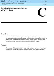
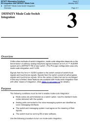
Chapter 4:Install Media ModulesThe required media modules are usually pre-installed in the <strong>G350</strong> chassis. If this is the case,skip this chapter.If the media modules are not pre-installed, or if you want to replace modules or add new mediamodules, install the necessary Media Modules and related components to support theconfiguration required <strong>for</strong> your site. If this Media Gateway needs to function as an ICC or as anLSP, install an S8300 Media Server module.Figure 5: The <strong>G350</strong> front panel ports and slots12 34567 8 910 11 12 13 14 1516 17Figure notes:1. V6 — high-density media module slot2. V2 — standard media module slot3. V5 — standard media module slot4. V1 — slot <strong>for</strong> standard media module or S8300 media server5. V4 — standard media module slot6. V3 — standard media module slot7. Analog port LEDs8. Analog trunk9. Analog line ports10. CCA (Contact Closure) port11. ETH WAN port12. ETH LAN port13. System LEDs14. Console port15. USB port16. RST button17. ASB buttonIssue 5 February 2007 19
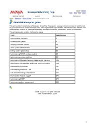
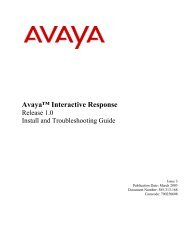
Install Media ModulesInstalling an S8300 Media Server ModuleThe S8300 can only be inserted in slot V1 on the left side of the <strong>Avaya</strong> <strong>G350</strong> Media Gateway.To install an S8300 Media Server Module:1. Remove the plate between slots V1 and V2, labeled “Remove be<strong>for</strong>e removing or insertingS8300 module.”2. Remove the blank plate from slot V1.3. Position the media module squarely be<strong>for</strong>e the V1 bay opening and engage both sides ofthe module in the interior guides.4. Slide the S8300 module slowly into the chassis. Maintain an even pressure to ensure thatthe module does not become twisted or disengaged from the guides.Figure 6: Inserting the S8300 media server module.5. Apply firm pressure to engage the connectors.6. Tighten the spring-loaded captive screws on the front of the module to lock the S8300Media Server module into the chassis.7. Replace the plate labeled “Remove be<strong>for</strong>e removing or inserting S8300 module” betweenslots V1 and V2. Tighten the screws on the front of the plate.20 <strong>Quick</strong> <strong>Start</strong> <strong>for</strong> <strong>Hardware</strong> <strong>Installation</strong> <strong>Avaya</strong> <strong>G350</strong> Media Gateway
Installing other Media ModulesInstalling other Media ModulesCombination LimitationsThe <strong>G350</strong> does not support all combinations of Media Modules. Be<strong>for</strong>e you insert other MediaModules, review the following list <strong>for</strong> combination limitations.The following limitations apply to combining media modules in the <strong>G350</strong>:● Maximum of one MM710 media module● Maximum of three of the following voice media modules in any combination: MM710,MM711, MM712, MM714, MM716, MM717, MM720, and MM722, subject to the followinglimitations:●●●●Maximum of one MM710Maximum of one of the following modules: MM712 and MM717 (you can combine thismodule with an MM312)No more than three MM711 and/or MM714No more than two MM716 and/or MM720 and/or MM722Inserting Media ModulesMedia Modules are restricted to certain slots. Ensure that you insert each module in a slotappropriate <strong>for</strong> that module. For a list of allowable slots <strong>for</strong> each Media Module, see Chapter 3of <strong>Installation</strong> and Upgrades <strong>for</strong> the <strong>Avaya</strong> <strong>G350</strong> Media Gateway, 03-300394.Insert the Media Modules needed <strong>for</strong> your configuration.Some Media Modules might require additional components. For example, the MM314 MediaModule requires a Gigabit Interface Connector (GBIC) to connect to the Gigabit Ethernet port.Issue 5 February 2007 21
Install Media Modules22 <strong>Quick</strong> <strong>Start</strong> <strong>for</strong> <strong>Hardware</strong> <strong>Installation</strong> <strong>Avaya</strong> <strong>G350</strong> Media Gateway
Chapter 5:Power UpGrounding RequirementsNote:Note: Grounding requirements differ widely from country to country. In addition to theinstructions <strong>for</strong> grounding presented in this section, you must follow the localelectrical installation codes <strong>for</strong> your location.You must use two safety grounds to ensure safe operation of the <strong>G350</strong> Media Gateway:●●The ground conductor that is part of the AC power cord.The field-installed green/yellow conductor, referred to as the supplementary groundconductor.Figure 7: Supplementary ground conductorBoth safety grounds must be connected to an approved ground (see Chapter 2 of <strong>Installation</strong>and Upgrades <strong>for</strong> the <strong>Avaya</strong> <strong>G350</strong> Media Gateway, 03-300394, <strong>for</strong> the definition of an approvedground). If a power cord accompanies the <strong>G350</strong>, use that cord whenever possible.WARNING:WARNING:! WARNING:Connection of both grounds (the AC power cord and the supplementary groundconductor) is required <strong>for</strong> safe operation of the <strong>G350</strong> Media Gateway.! WARNING:An improper ground can cause electrical shock, equipment failures, and serviceoutages.Issue 5 February 2007 23
Power UpConnecting Ground ConductorsTo attach the ground wires:1. Remove the ground screw on the rear of the chassis adjacent to the ground symbol.2. Place the ring terminal of the 10 AWG (4 mm 2 ) supplementary ground conductor on thescrew.3. Replace the ground screw on the chassis and securely tighten the screw so the screwcannot be loosened without the use of a tool.4. Attach the supplementary ground conductor to an approved ground.Using a Ground BlockA ground block might be provided <strong>for</strong> use with multiple Media Gateway installations. Usually, thecustomer electrician mounts the ground block.To attach the supplementary ground conductor (that is already attached to the grounding screwon the chassis) to a ground block:1. Cut the supplementary ground conductor to the length needed to terminate the conductorinto one of the terminals of the ground block. Do not coil the supplementary groundconductor.2. Attach one end of the remaining 10 AWG (4 mm 2 ) ground wire to one of the terminals in theground block and the other end to an approved ground. Cut this ground wire to the lengthneeded to reach the approved ground. Do not coil this wire.24 <strong>Quick</strong> <strong>Start</strong> <strong>for</strong> <strong>Hardware</strong> <strong>Installation</strong> <strong>Avaya</strong> <strong>G350</strong> Media Gateway
Connecting PowerConnecting PowerTo connect the power:1. Connect the AC power cable to the inlet receptacle on the rear of the chassis.2. Connect the other end of the power cable into a mains socket.LED SequenceWhen you turn on the <strong>G350</strong>, the following LED sequence occurs:1. The PWR LED on the front panel lights.2. The CPU LED lights if the firmware is running.3. At least one LED on each media module lights initially and then goes off after about 20seconds.Issue 5 February 2007 25
Power Up26 <strong>Quick</strong> <strong>Start</strong> <strong>for</strong> <strong>Hardware</strong> <strong>Installation</strong> <strong>Avaya</strong> <strong>G350</strong> Media Gateway
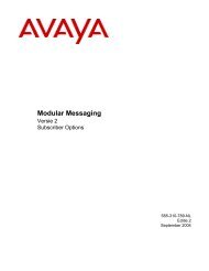
Chapter 6:Prepare <strong>for</strong> ConfigurationBe<strong>for</strong>e you prepare the <strong>G350</strong> <strong>for</strong> configuration, ensure that you load the completed ElectronicPre-<strong>Installation</strong> Worksheet onto the laptop. You should also load any firmware, license, orauthentication files that you have prepared onto the laptop.Preparations <strong>for</strong> configuration differ depending on whether your <strong>G350</strong> contains an S8300 MediaServer. The following section describes the preparation of a <strong>G350</strong> that includes an S8300Media Server. If your <strong>G350</strong> does not include an S8300 Media Server, skip to Configuring a<strong>G350</strong> without an S8300 Media Server on page 33.Preparing a <strong>G350</strong> with an S8300 Media ServerUse the <strong>Avaya</strong> <strong>Installation</strong> Wizard (IW) to configure the <strong>G350</strong> with an S8300. If a remotetechnician is configuring the <strong>G350</strong>, see Preparing the <strong>G350</strong> with an S8300 <strong>for</strong> a remoteconfiguration on page 32.To prepare the S8300 <strong>for</strong> configuration:1. Connect the laptop you prepared to the Services port on the S8300. Use a standardEthernet crossover cable.2. Configure the network settings on the laptop, according to the following tables:Table 3: TCP/IP settingsSettingValueIP Address 192.11.13.5Subnet Mask 255.255.255.252DNSWINS Serversdisabledo not use (clear any values)Table 4: Internet Explorer SettingsSettingProxy ServerValuedisable3. Open Internet Explorer, and browse to 192.11.13.6. The Welcome screen appears.Issue 5 February 2007 27
Prepare <strong>for</strong> Configuration4. Click Continue on the Welcome screen. The Logon screen appears.5. Logon on the Logon screen, and click Logon. The main menu <strong>for</strong> <strong>Avaya</strong> IntegratedManagement appears.Figure 8: Integrated Management Main Menu6. Ask a customer representative <strong>for</strong> a login name and password that the customer would like<strong>for</strong> the superuser login. If you are a business partner, you can also repeat this procedure toadd the dadmin login.Note:Note:Make sure the customer can change this login, its password, or its permissionslater.28 <strong>Quick</strong> <strong>Start</strong> <strong>for</strong> <strong>Hardware</strong> <strong>Installation</strong> <strong>Avaya</strong> <strong>G350</strong> Media Gateway
Preparing a <strong>G350</strong> with an S8300 Media Server7. Under Security, select Administrator Accounts.The Administrator Accounts screen appears.8. Type the login name in the Enter Login ID or Group Name field.Issue 5 February 2007 29
Prepare <strong>for</strong> Configuration9. Select Add Login, and click Submit.The Administrator Logins -- Add Login screen appears.10. Type susers in the login group field.11. Type prof18 in the additional groups field. prof18 is the code <strong>for</strong> the customer superuser.12. Select the allow Linux shell access check box.13. For the select type of authentication option, select password.30 <strong>Quick</strong> <strong>Start</strong> <strong>for</strong> <strong>Hardware</strong> <strong>Installation</strong> <strong>Avaya</strong> <strong>G350</strong> Media Gateway
Preparing a <strong>G350</strong> with an S8300 Media Server14. Complete the following fields:●enter key or password● re-enter key or password15. Specify whether to <strong>for</strong>ce password/key change on first login.Note:Note: Do not lock the account or set the password to be disabled.16. Leave the defaults in the remaining fields.17. Click Add.The system in<strong>for</strong>ms you the login is added successfully.18. From the Integrated Management main menu, select Launch <strong>Avaya</strong> IW. The <strong>Avaya</strong><strong>Installation</strong> Wizard (IW) opening screen appears.To configure the S8300 using the <strong>Avaya</strong> IW:Step through the pages of the <strong>Avaya</strong> IW to configure the S8300 and the <strong>G350</strong>. Take note of thefollowing items:1. On the initial IW page, you can upgrade the wizard if you have a more current version of theAIW.rpm wizard file. You can download the most current version of the AIW.rpm wizard filefrom the <strong>Avaya</strong> Web site at http://support.avaya.com/avayaiw. The <strong>for</strong>mat of the name ofthe file is si_S8300-.noarch.rpm, where is the <strong>Avaya</strong>IW version number.2. On the Import EPW page, import the Electronic Pre-<strong>Installation</strong> Worksheet (EPW) that wasprepared.3. On the Usage Options page, verify the role of this S8300 server.4. Use the NVRAM Init page to initialize the <strong>G350</strong>.5. On the Date/Time page, set the correct date, time, and time zone.6. Upgrade the Communication Manager software to the latest version on the SoftwareUpgrade page.7. If you have a software update (patch) file <strong>for</strong> Communication Manager, use the SoftwareUpdate page to select the file and update the software.8. If you are not using IW to generate basic translations, select the Translation will be addedafter the installation option on the Translation Source page.9. On the Security File page, load the License file that you prepared from your laptop.Issue 5 February 2007 31
Prepare <strong>for</strong> ConfigurationNote:Note:As of Communication Manager Release 3.1, the <strong>Avaya</strong> IW no longer requires theinclusion of the FEAT_DADMIN login permissions in the license in order togenerate basic translations. However, <strong>for</strong> Business Partners, the license may stillinclude the FEAT_DADMIN login permissions. If the license does include theFEAT_DADMIN login permissions, and you are using IW to generate basictranslations, initially you load a license file with the DADMIN feature enabled. Atthe conclusion of the <strong>Avaya</strong> IW configuration, you load a second license file withthe DADMIN feature disabled.10. On the Media Gateway IP Address page, click to configure the <strong>G350</strong>.11. On the Firmware page, upgrade <strong>G350</strong> and Media Module firmware. New firmware files canbe loaded from your laptop directly into the Media Server /tftpboot directory, if needed.12. Use the Change Master Key - Optional screen to optionally change the master key which isused to encrypt gateway secrets (passwords, etc.) in the gateway configuration file.13. If you will be using the VPN feature, use the Gateway License screen to install the gatewaylicense file.14. On the Authentication File page, load the Authentication file that you prepared from yourlaptop.Preparing the <strong>G350</strong> with an S8300 <strong>for</strong> a remote configurationIf you need to prepare the <strong>G350</strong> with an S8300 <strong>for</strong> a remote configuration, you must attach andenable a modem.To prepare the <strong>G350</strong> with an S8300 <strong>for</strong> a remote configuration:1. Connect a USB modem to one of the USB ports on the S8300 Media Server.2. From the Integrated Management Main Menu select Launch Maintenance Web Interface(see Figure 8: Integrated Management Main Menu on page 28).3. Use the Maintenance Web Pages to enable the modem.4. To ensure that the modem is enabled correctly, setup a dialup connection on a remote PCwith the following settings:●●Automatically detect settings.No Username, Password, or Domain.● Security > Show Terminal Window.5. Dial in to the modem from the remote PC.32 <strong>Quick</strong> <strong>Start</strong> <strong>for</strong> <strong>Hardware</strong> <strong>Installation</strong> <strong>Avaya</strong> <strong>G350</strong> Media Gateway
Configuring a <strong>G350</strong> without an S8300 Media Server6. When prompted, provide the rasaccess login and password in the Terminal Window.7. Close the Terminal Window to complete the connection.8. A remote technician can now access the S8300 remotely and run <strong>Avaya</strong> IW. Open InternetExplorer and browse to 10.3.0.1.Configuring a <strong>G350</strong> without an S8300 Media ServerYou use the Gateway <strong>Installation</strong> Wizard (GIW) to configure the <strong>Avaya</strong> <strong>G350</strong> Media Gatewaywithout an S8300. You can per<strong>for</strong>m the configuration on site, or prepare the <strong>G350</strong> <strong>for</strong> a remoteconfiguration.To configure the <strong>G350</strong> using GIW:1. Install the GIW software on your laptop. You can download the GIW software from the<strong>Avaya</strong> support Web site, at http://support.avaya.com/avayaiw and go to File Downloads.2. Connect the flat RJ-45 to RJ-45 cable to the DB-9 cable adapter.3. Plug the RJ-45 cable into the Console port of the <strong>G350</strong> (labeled CONSOLE).4. Plug the DB-9 end of the cable into a COM port of the laptop.5. Double-click the GIW icon on the laptop to open the Gateway <strong>Installation</strong> Wizard. TheOverview screen appears.6. Click Continue. The COM Port Selection screen appears.7. Select the COM port you are using on the laptop to connect to the <strong>G350</strong> from the COM Portdrop down list.Note:Note: Not every COM port works with every laptop. If you have trouble connectingusing the COM port you have selected, try a different COM port.8. Click Continue. The Wizard Usage Options screen appears.9. To per<strong>for</strong>m an on site configuration using the GIW, continue with the next section. Toprepare <strong>for</strong> a remote configuration, continue with Preparing <strong>for</strong> a remote configuration of the<strong>G350</strong> on page 34.To configure the <strong>G350</strong> on site:1. From the Wizard Usage Options screen, select Continue the installation using thiswizard, and click Continue.2. On the Initialize Components screen, check the options that are appropriate <strong>for</strong> yourinstallation.3. On the Import EPW screen, import the Electronic Pre-<strong>Installation</strong> Worksheet (EPW) thatwas prepared.Issue 5 February 2007 33
Prepare <strong>for</strong> Configuration4. Use the IP Address screen to configure addresses and communication parameters <strong>for</strong> the<strong>G350</strong>. Click to configure the following in<strong>for</strong>mation <strong>for</strong> the media gateway:a. Use the PMI screen to specify the details of the Primary Management Interface of the<strong>G350</strong>.b. Use the SNMP screen to specify SNMP community strings and trap destinations.c. Use the MGC List screen to specify the Media Gateway Controller(s) used to manage the<strong>G350</strong>, and the Transition Point in<strong>for</strong>mation. Click Ping Test to test the accessibility ofeach MGC.5. On the Firmware screen, identify the TFTP server used <strong>for</strong> file transfer, and specify thefirmware upgrade files to load.6. Use the Change Master Key - Optional screen to optionally change the master key which isused to encrypt gateway secrets (passwords, etc.) in the gateway configuration file.7. If you will be using the VPN feature, use the Gateway License screen to install the gatewaylicense file.8. Use the <strong>G350</strong> Modem Type Selection screen to enable a modem attached to the <strong>G350</strong>.9. Use the Change Root Password screen to set the root password <strong>for</strong> the <strong>G350</strong>.10. Click Finish to complete the <strong>G350</strong> configuration.Preparing <strong>for</strong> a remote configuration of the <strong>G350</strong>If you need to prepare the <strong>G350</strong> <strong>for</strong> a remote configuration, you must attach a modem andenable it using the GIW.To prepare <strong>for</strong> a remote configuration:1. From the Wizard Usage Options screen, select Enable the modem <strong>for</strong> remoteinstallation, and click Continue. The Modem Type Selection screen appears.2. Select the type of modem you are using, and click Continue.3. Verify that the modem parameters are correct <strong>for</strong> the type of modem that you selected. ClickContinue. The Connect Modem screen appears.4. From the Connect Modem screen, click Finish to exit the Gateway <strong>Installation</strong> Wizard.5. Connect the modem that you specified in Step 2.6. Dial in to the modem to ensure that it is set up correctly.7. A remote technician can now dial in to the <strong>G350</strong> and complete the configuration using theCLI interface.34 <strong>Quick</strong> <strong>Start</strong> <strong>for</strong> <strong>Hardware</strong> <strong>Installation</strong> <strong>Avaya</strong> <strong>G350</strong> Media Gateway
Next StepsNext StepsUsing <strong>Avaya</strong> IW and GIWThe full configuration process is per<strong>for</strong>med using the <strong>Avaya</strong> <strong>Installation</strong> Wizard or Gateway<strong>Installation</strong> Wizard interface. For more detailed in<strong>for</strong>mation about IW and GIW:●●See the online help <strong>for</strong> IW and GIW at http://support.avaya.com/avayaiw.Review Job Aid: <strong>Avaya</strong> <strong>Installation</strong> Wizard, 555-245-754, and Job Aid: <strong>Avaya</strong> Gateway<strong>Installation</strong> Wizard, 555-245-756.Using the Command Line InterfaceFor in<strong>for</strong>mation about configuring the <strong>G350</strong> with the Command Line Interface:●●For instructions on how to connect to the CLI, review Chapter 3 of Administration <strong>for</strong> the<strong>Avaya</strong> G250 and <strong>Avaya</strong> <strong>G350</strong> Media Gateways, 03-300436 - Accessing the <strong>Avaya</strong> <strong>G350</strong>Media Gateway.For detailed in<strong>for</strong>mation about CLI commands, refer to the <strong>Avaya</strong> G250 and <strong>Avaya</strong> <strong>G350</strong>CLI Reference, 03-300437.Issue 5 February 2007 35
Prepare <strong>for</strong> Configuration36 <strong>Quick</strong> <strong>Start</strong> <strong>for</strong> <strong>Hardware</strong> <strong>Installation</strong> <strong>Avaya</strong> <strong>G350</strong> Media Gateway